Article

Multiphysics Field Distribution Characteristics within the One-Cell Solid Oxide Fuel Cell Stack with Typical Interdigitated Flow Channels

1
School of Energy and Power, Jiangsu University of Science and Technology, Zhenjiang 212003, China
2
eTrust Power Group Ltd., Zhenjiang 212000, China
3
Institute of Mechanics and Energy, Ogarev Mordovia State University, 430000 Saransk, Russia
*
Author to whom correspondence should be addressed.
Appl. Sci. 2019, 9(6), 1190; https://doi.org/10.3390/app9061190
Submission received: 5 March 2019 / Revised: 16 March 2019 / Accepted: 17 March 2019 / Published: 20 March 2019
(This article belongs to the Section Energy Science and Technology)

Abstract

:
Generally, the manufacturing technology of fuel cell units is considered to satisfy the current commercialization requirements. However, achieving a high-performance and durable stack design is still an obstacle in its commercialization. The solid oxide fuel cell (SOFC) stack is considered to have performance characteristics that are distinct from the proton exchange membrane fuel cell (PEMFC) stacks. Within the SOFC stack, vapor is produced on the anode side instead of the cathode side and high flow resistance within the fuel flow path is recommended. In this paper, a 3D multiphysics model for a one-cell SOFC stack with the interdigitated channels for fuel flow path and conventional paralleled line-type rib channels for air flow path is firstly developed to predict the multiphysics distribution details. The model consists of all the stack components and couples well the momentum, species, and energy conservation and the quasi-electrochemical equations. Through the developed model, we can get the working details within those SOFC stacks with the above interdigitated flow channel features, such as the fuel and air flow feeding qualities over the electrode surface, hydrogen and oxygen concentration distributions within the porous electrodes, temperature gradient distribution characteristics, and so on. The simulated result shows that the multiphysics field distribution characteristics within the SOFC and PEMFC stacks with interdigitated flow channels feature could be very different. The SOFC stack using the paralleled line-type rib channels for air flow path and adopting the interdigitated flow channels for the fuel flow path can be expected to have good collaborative performances in the multiphysics field. This design would have good potential application after being experimentally confirmed.

1. Introduction

As one of the most potential energy conversion devices, the solid oxide fuel cell (SOFC) has attracted attention due to its advantages of low pollution and noise and high energy conversion efficiency [1,2]. It can be practically applied in many fields, such as mobile power, aerospace, submarines, and so on; and has a broad application prospect [3,4]. In the past decades, many novel materials [5,6,7,8,9] and fuel cell unit types [10,11] have been proposed and developed due to the contributions of a large number of scientists and funding support. Generally, the current art of the fuel cell unit manufacture technology and performance can well satisfy the commercialization requirements [12,13,14]. However, when the SOFC units are constructed into a stack, the average performance of the units is greatly decreased. Thus, achieving the high performance and durability of the stack design is still one of the key factors for commercializing SOFC technology on a stack level.
In the past decades, many different structure designs of SOFC have been proposed and the 3D numerical approach was proven to be the proper approach to study the working details within the stack and achieve optimized geometric parameters [15,16,17]. Nishida et al. [16] described the development and application of a new computational fluid dynamics model that allows large SOFC stacks to be studied within a practical calculation time. This model was used to demonstrate that the flow distribution of each cell in the 100-cell stack significantly affected the temperature distribution and overall electrochemical performance. The 3D large-scale multiphysics models were developed to find out the effect of the key structure parameters on the air flow distribution features within the planar SOFC stacks [18]. Chen et al. [19] developed a large-scale 3D multiphysics model to figure out the multiphysics field distribution features within those fuel cell stacks with manifolds penetrating through the plane zone and open outlet features. Hwang et al. [20] have discussed the temperature distribution quality between two proton exchange membrane fuel cell (PEMFC) stacks with conventional rib and interdigitated rib cases, respectively. It was found that replacing the traditional straight ribs with interdigitated ribs would increase the local maximum temperature value inside the PEMFC. Grujicic et al. [21] studied the properties of the cathode and interdigitated ribs in a typical PEMFC stack and found that using the interdigitated ribs could enhance the migration of oxygen within the porous cathode. The interdigitated design promotes forced diffusion of the reactant gas in the porous medium. Studies have shown that the water management effect of this design was much better than other designs of PEMFC stacks because it can improve the vapor transmission within the porous cathode [20,22].
Generally, the SOFC stack is considered to have characteristics that are distinct from the PEMFC stack. Firstly, within the SOFC stack, the vapor is produced on the anode side instead of on the cathode side of the PEMFC stack. Secondly, high flow resistance within the fuel flow path of the SOFC stack is recommended because of the consideration of high fuel utilization and low molecular mass. Conversely, low flow resistance within the air flow path of the SOFC stack is recommended to reduce the additional pump requirement because air flow is the main heat carrier within the SOFC stack and its large molecular mass and velocity will lead to a high pressure drop. Thus, a SOFC stack with an interdigitated design for the fuel flow path and conventional paralleled line-type rib channels for the air flow path may be expected to have good performance. In this paper, a steady 3D numerical model for a one-cell SOFC stack with the above design structure is developed, which couples the momentum, species, energy, and quasi-electrochemical control equations. Then, it will be used to calculate and figure out the multiphysics distribution details within those stacks with the above interdigitated fuel rib channels feature. The difference in the multiphysics field distribution characteristics between the SOFC and PEMFC stacks will then be found while the interdigitated rib channels are used. Whether the proposed SOFC stack—which adopts interdigitated rib channels for fuel flow and conventional paralleled line-type rib channels for air flow—can support good collaborative performances among the multiphysics fields will be checked. Most of the conclusions would be very useful for us to further understand the working details within the planar SOFC stacks with the above features and perform further parameter optimizations of the SOFC stacks in the near future.

2. Structure, Theory, and Numerical Model

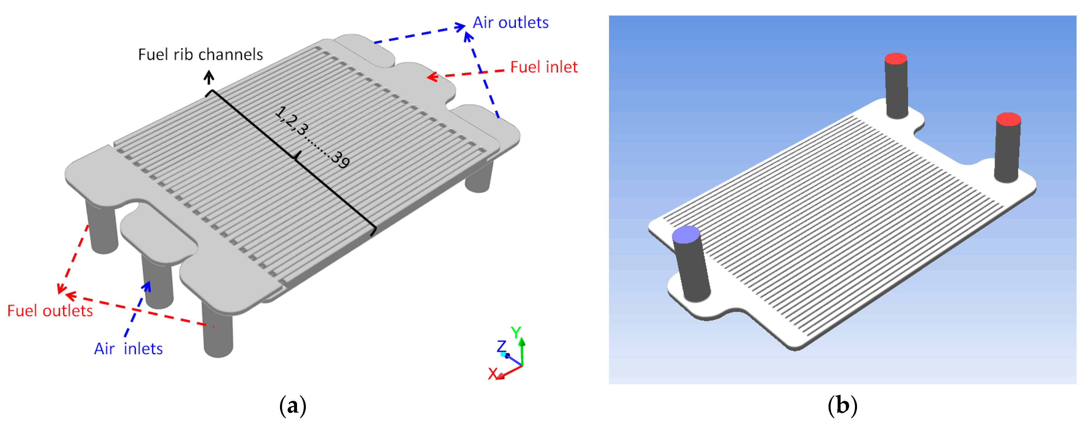
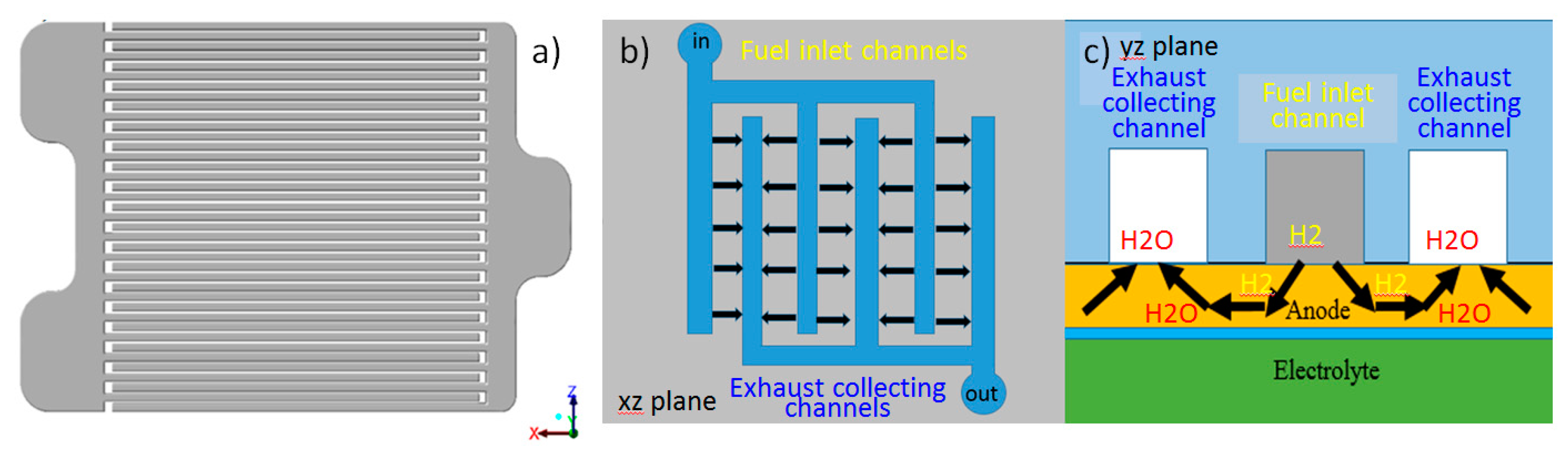
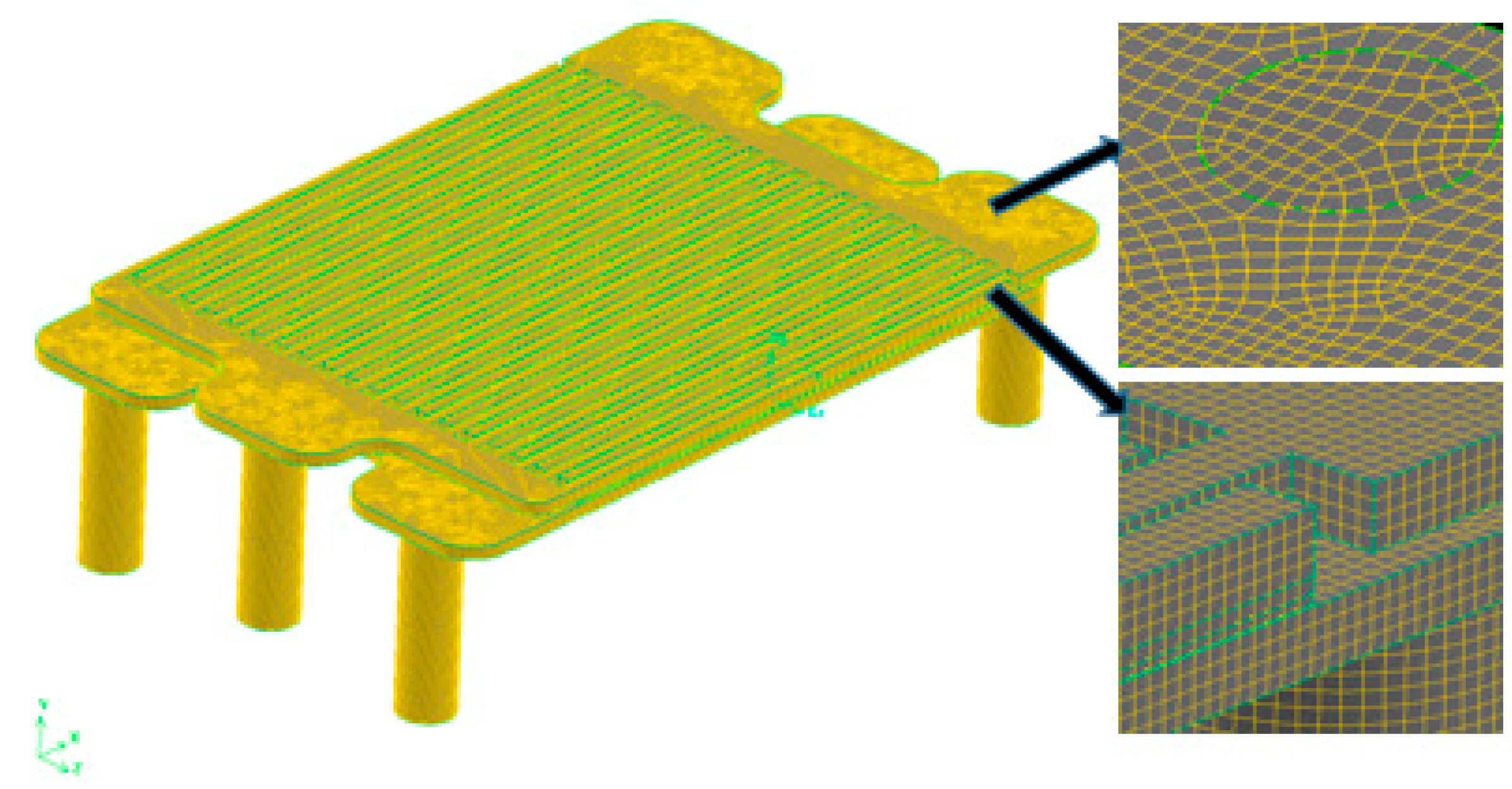
2.1. Model Structure and Mesh

In Figure 1a, the schematic diagram of a one-cell SOFC stack with an interdigital fuel flow rib channel design and conventional paralleled line-type rib channels of the air flow path is displayed. The core part, SOFC unit, includes the porous anode, dense electrolyte, and porous cathode; their corresponding reaction area is 100 × 100 mm. The fuel and air flow paths are two important study parts. The fuel and air flow arrangement in Figure 1a is a counterflow type. The fuel and air flow manifold configurations are both ‘1 in 2 out’ with radii of 5 mm. The ‘1 in 2 out’ here means one inlet manifold at one side and two outlet manifolds at the other side.
Fuel and air flows are further distributed over the anode and cathode surfaces, respectively, by the rib channels. Figure 1b shows the conventional paralleled line-type rib channels over the porous cathode surface. This design type was reported to have a lower pressure drop throughout the stack compared with the other structure designs [23]. As shown in the figure, the air rib channels are separated by 39 solid ribs. The length of each flow channel is 100 mm, and the width and height of the ribs are 2 mm and 2 mm, respectively. This configuration is considered to be a proper choice for the cathode side. The reason is that the mole fraction of O2 within the supplied air flow gas is only 21% and the air flow utilization within SOFC stacks may be only around 30% [24]. Thus, there is a large amount of air flow mass supply rate on the stack level. Adopting a lower flow resistance design is good to achieve a relatively lower pressure drop between the stack entrance and exit [18,23].
Different from the air flow path, high resistance-designed fuel flow path is recommended to achieve high fuel utilization due to the relative light molecular mass of fuel and the low fuel flow mass supply rate of the stack. Figure 2a shows the fuel flow path structure with the interdigitated feature. There are 20 rib channels for the fuel input and 19 rib channels for collecting the exhaust gas. Figure 2a displays the schematic diagram of the interdigitated design in the y-direction view. Obviously, the fuel entering the fuel input channels is not directly connected with the exhaust channels of the outlet. In other words, the gas transmission between the fuel input and exhaust channels depends mainly on the connection of the porous anode. As further illustrated in Figure 2c, the gas can be carried out through the porous anode in both the lateral and longitudinal directions, simultaneously. Fuel from the input rib channels can be diffused to the electrochemical reaction sites within the porous anode and over the anode/electrolyte interface through the porous anode structure. Then, the exhaust gas, such as the electrochemical reaction production (i.e., vapor) and the unused fuel will be transported back into the exhaust collecting channels directly through the porous anode structure. The gap between the fuel flow channels is only 0.5 mm, which can increase the gas penetration cross-section to improve the effective reaction area of the SOFC unit. This interdigitated design for the fuel flow path is expected to improve both the fuel and vapor management qualities within the SOFC stack.
The meshing process is one of the key steps to ensuring the calculation accuracy of the numerical simulation [25]. In Figure 3, meshes of the whole stack and the partial enlargement picture are displayed to illustrate the meshing quality. The meshes include sub-channel, cell unit, manifold, and interconnector zones. The mesh number of each rib channel is 4 × 4 in the height and width directions. Each SOFC unit has a total of 680,716 mesh cells, and the meshes at the electrodes are encrypted. The meshes for the inlet and outlet manifolds are twice as large as those of the channels because these areas have only pure fluid flow and mesh encryption is not necessary. There is no difference in the meshes between the anode, cathode, and electrolyte layers; and they are uniformly set to the same size meshes. From the model’s overall structural mesh diagram and locally enlarged diagram, the SOFC unit has a very high mesh quality, and hexahedral meshes are used. The meshes do not have a large length and width aspect ratio, which guarantees the correctness and efficiency of the calculation.

2.2. Governing Equations

The 3D one-cell stack model in this paper couples mass conservation, momentum conservation, energy conservation, species conservation, and quasi-electrochemical control equations. Coupling calculation is a complex process, and how to calculate efficiently is a difficulty. The specific description of the control equations is as follows.
The continuity equation for the mixture gas is:
( ε ρ u ) = S m .
All fluid flow processes follow this basic rule. In the equation, ε is the porosity of the porous electrode (porosity refers to the proportion of the void space in the porous to the total volume of the electrode), u is the fluid velocity, and ρ is the density of the fluid. The higher the porosity, the higher is the molecular pass rate. This equation is effective for both incompressible and compressible flows:
( 1 ε 2 ρ u u ) = ε p + ( ε μ e f f u ) + S u .
Equation (2) is the momentum conservation equation for the fluid part of the stack: p is the pressure of the fluid, μ e f f is the effective viscosity coefficient of the fluid, and S u is the source item, which does not exist in the momentum conservation equations in the manifold and flow channel zones. S u only exists at the interface between the electrode and dense electrolyte. The gas consumption and production occur at this interface, and this process will change the fluid concentration [26].
( ε u C k ) = ( D k , e f f C k ) + S k .
Equation (3) is the conservation of species where C k is used to represent the mass fraction of species k; D k , e f f is the effective diffusion coefficient of species k; and S k is the source item at the interface between the electrode and dense electrolyte. S k for species k in the cathode and anode sides can be respectively estimated as:
S O 2 = i out M O 2 4 F , S N 2 = 0 S H 2 = i out M H 2 2 F , S H 2 O = i out M H 2 O 2 F
S k is 0 in the manifold and flow channel zones.
t ( p E ) + ( v ( p E + p ) ) = ( k e f f T J h j J j + ( τ ¯ e f f v ) ) + S h .
Equation (5) is the energy conservation equation where K e f f is the effective thermal conductivity ( k + k t , where k t is the turbulent thermal conductivity, as defined by the turbulence mode) and J j is the diffusion flux of species j . The first three items on the right side of the equation represent the energy transfer due to the thermal conduction of the gas, the diffusion of species, and the viscous dissipation.
Generally, it is quite difficult to consider the electrochemical reaction details around the three phase boundary sites within the composite electrode. Thus, the heat sources corresponding to the reaction and ohmic heats are assumed to be uniformly produced within the whole porous anode and cathode. In this case, S h includes the heat of the chemical reaction and any other volumetric heat source. The heat source item S h can be simply evaluated for:
S h = i op ( Δ h 2 F V out ) / 2 l ,
where Δ h is the molar enthalpy change in the electrochemical reaction, V out is the cell output voltage, F is the Faraday constant, and l is the actual electrode thickness involved in the electrochemical reaction.

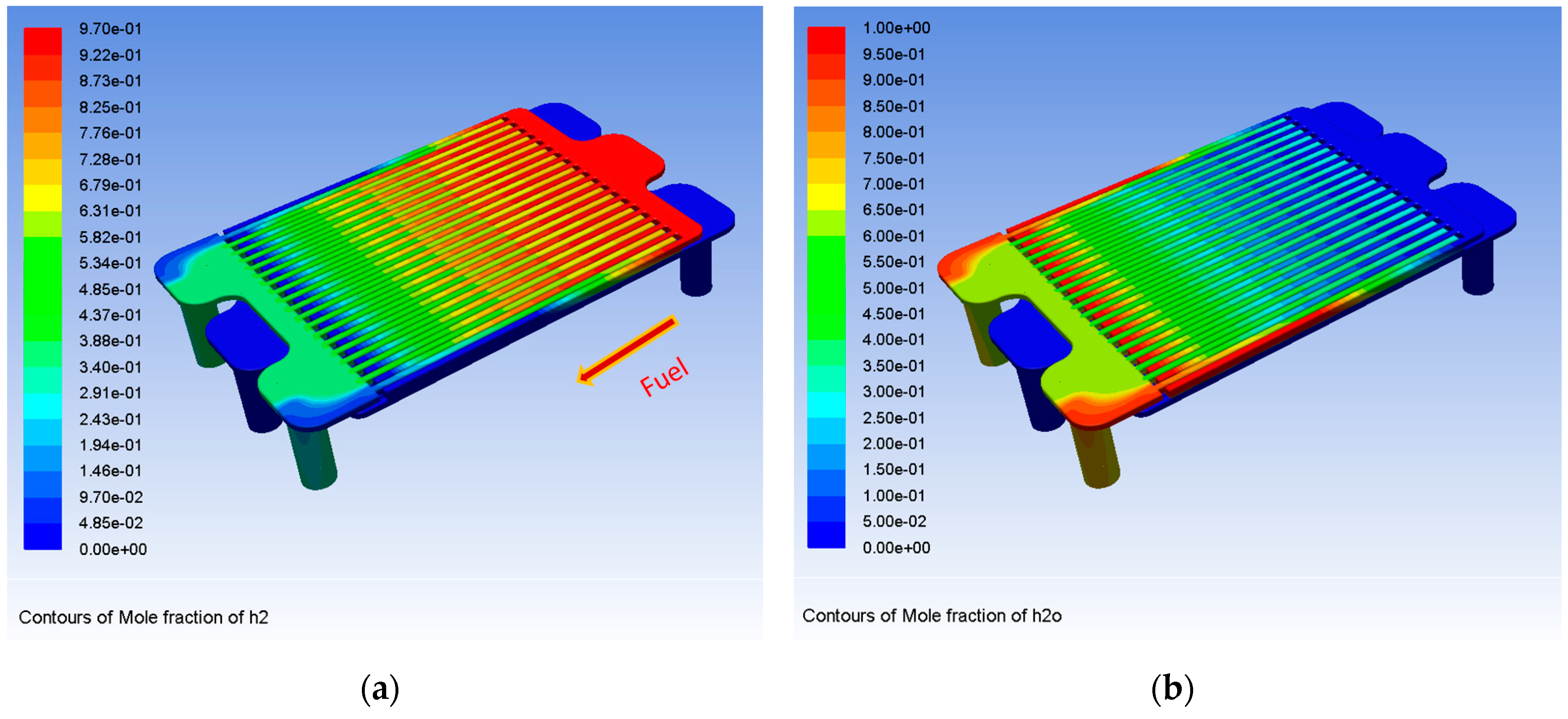
3. Results and Discussion

Firstly, the mole fraction of H2 in the anode side is shown in Figure 4a. Fuels are fed over the porous anode surface through the input rib channels. Then, they will be transported to the anode–electrolyte interface through the porous anode. In these reaction sites, most of the fuel will be consumed. Then, the unused fuel and vapor produced will be transported to the exhaust rib channels as shown in Figure 2. Thus, we can get that the H2 mole fraction in the 20 input rib channels is larger than that in the 19 exhaust rib channels. Similarly, Figure 4b shows the H2O mole fraction distribution among the total 39 rib channels. Obviously, the H2O mole fractions in the 19 exhaust rib channels are larger than that in the 20 input rib channels. From this result, we can get that using the interdigitated design for rib channels of the fuel flow path is good for managing the H2 and vapor flows. H2 will be fed over the porous anode by the input rib channels, and most of the production (i.e., vapor) will be collected by the exhaust rib channels directly. This conclusion is similar to that in the PEMFC cathode as reported by Ni et al. [27].
To further get the H2 and H2O transporting qualities within the porous anode for the interdigitated design, Figure 5a,b show the H2 and H2O mole fraction distribution features over the anode–electrolyte interface, respectively. As the support layer of the current SOFC is a porous anode, H2 can fully diffuse into the porous anode with relatively low resistance. This makes the distribution of the H2 mole fraction over the anode–electrolyte interface (vertical to the fuel flow direction) more uniform (as Figure 5a). Obviously, the H2 transport within the interdigitated design can be enhanced compared to other designs because of the rising static pressure within the input rib channels. A similar result for the molar fraction distribution of H2O in Figure 5b also illustrates well the vapor transporting capability within the porous anode, while the SOFC stack adopts an interdigitated design for the fuel flow path.
Figure 6 shows the oxygen mole fraction distribution characteristic within the cathode air flow path. Obviously, the O2 mole fraction within the rib channels will decrease along the air flow direction. However, the mole fraction changes are relatively small due to the conventional line-type configuration of the rib channels and high air flow supply rate of the stack. Different from the PEMFC stack case, the vapor is produced on the anode side of the SOFC stack. For the SOFC stack, the air flow will not only act as the reactant, it will also act as the main heat transfer carrier. Thus, the high air flow supply rate of the SOFC stack and the large molecular mass determine that a low flow resistance flow path is recommended. Thus, different from the PEMFC case, an interdigitated design is not a good choice for the air flow path in the SOFC stack, based on the above described three factors.
Generally, the temperature gradient within the stack would greatly affect the performance and durability of the SOFC stack. Figure 7 shows the overall temperature distribution within the one-cell SOFC stack. It shows that the rib channel temperature change at the H2 inlet side is higher than the other channels. The temperature rises instantly when H2 enters the channels, almost reaching the maximum temperature of the stack. On the other hand, the temperature of the air inlet side of the cell changes more uniformly. Then, the temperature rises gradually along the direction of air flow, and the highest temperature occurs near the air outlet. The reason is that the temperature distribution in the stack will increase along the direction of the fluid flow because fluids are the main heat carriers within the SOFC stack. However, as there are low fuel flow rates due to the consideration of high fuel utilization and high air flow rates due to the cooling necessary, the effect of fuel on the cell temperature change is very small. Thus, the temperature within the stack will increase along the air flow direction as shown in Figure 7.
Generally, the temperature distribution within the SOFC stack is closely related to the air flow distribution characteristics within the air flow path [18]. Figure 8a further shows the normalized air mass flow rate distributions obtained by the rib channels, m . It is the ratio of the actual flow to the average flow rate of all channels. It can be seen that the relatively large flow rates appear in the middle channels of the cell, while the flow rates obtained on both sides of the cell unit are relatively small. The mass distributions are still relatively uniform. Although the flow rates obtained on both sides are less than those in the middle zone, the difference is not great.
Figure 8b further shows the temperature distributions across the channels. It can be found that the lowest temperature in the channels occurs in the middle of the cell. The temperature on the two sides of the cell is relatively high, but the temperature does not change much. In contrast to Figure 8a, the channels with a large flow rate have a lower temperature because air is the main heat transfer medium. However, the temperatures of the flow channels on both sides of the cell are lower. Since the anode generates a large amount of H2O that collects in these ribs, it has a higher specific heat capacity. Obviously, with increasing the air flow rates, the temperatures become lower. This result supports well the conclusion obtained above.

4. Conclusions

In this paper, the 3D multiphysics model for the one-cell SOFC stack with an interdigitated flow channels feature has been well developed. The developed model can be used to get the distribution details of the hydrogen, vapor, and oxygen concentrations, temperature, and flow rates within the stack. We can achieve the following conclusions from the calculated results. Firstly, the multiphysics field distribution characteristics within the SOFC and PEMFC stacks with interdigitated flow channels feature could be very different due to their very different working features as described in the introduction section. Secondly, the SOFC stack using the paralleled line-type rib channels for the air flow path and adopting the interdigitated flow channels for the fuel flow path can be expected to have good collaborative performances among the multiphysics fields. Most of the results achieved in the current paper provide a good guideline for experimental and parameter researchers on stacks with a similar interdigitated flow channels feature.

Author Contributions

Data curation, Y.X. and A.K.; Investigation, W.Y.; writing—original draft preparation, Y.X.; writing—review and editing, D.C. All authors read and approved the final manuscript.

Funding

This research was funded by the financial support of the National Natural Science Foundation of China (51776092 and 21406095) and the Natural Science Foundation of Jiangsu Province BK20151325.

Conflicts of Interest

The authors declare no conflicts of interest.

References

  1. Duan, C.; Tong, J.; Shang, M.; Nikodemski, S.; Sanders, M.; Ricote, S.; Almansoori, A.; O’Hayre, R. Readily processed protonic ceramic fuel cells with high performance at low temperatures. Science 2015, 349, 1321–1326. [Google Scholar] [CrossRef] [PubMed]
  2. Chen, D.; Hu, B.; Ding, K.; Yan, C.; Lu, L. The Geometry Effect of Cathode/Anode Areas Ratio on Electrochemical Performance of Button Fuel Cell Using Mixed Conducting Materials. Energies 2018, 11, 1875. [Google Scholar] [CrossRef]
  3. Ni, M.; Shao, Z.; Chan, K. Modeling of Proton-Conducting Solid Oxide Fuel Cells Fueled with Syngas. Energies 2014, 7, 4381. [Google Scholar] [CrossRef]
  4. Chen, D.; Xu, Y.; Hu, B.; Yan, C.; Lu, L. Investigation of proper external air flow path for tubular fuel cell stacks with an anode support feature. Energy Convers. Manag. 2018, 171, 807–814. [Google Scholar] [CrossRef]
  5. Seymour, I.D.; Chroneos, A.; Kilner, J.A.; Grimes, R.W. Defect processes in orthorhombic LnBaCo2O5.5 double perovskites. Phys. Chem. Chem. Phys. 2011, 13, 15305–15310. [Google Scholar] [CrossRef]
  6. Seymour, I.D.; Tarancón, A.; Chroneos, A.; Parfitt, D.; Kilner, J.A.; Grimes, R.W. Anisotropic oxygen diffusion in PrBaCo2O5.5 double perovskites. Solid State Ion. 2012, 216, 41–43. [Google Scholar] [CrossRef]
  7. Lu, L.; Zeng, W.; Hu, S.; Chen, D.; Lei, J.; Ren, N. Polarization-dependent fluorescence of CdSe/ZnS quantum dots coupling to a single gold-silver alloy nanotube. J. Alloy. Compd. 2018, 731 (Suppl. C), 753–759. [Google Scholar] [CrossRef]
  8. Xiao, B.B.; Jiang, X.B.; Jiang, Q. Density functional theory study of oxygen reduction reaction on Pt/Pd3Al(111) alloy electrocatalyst. Phys. Chem. Chem. Phys. 2016, 18, 14234–14243. [Google Scholar] [CrossRef]
  9. Qu, Z.; Shi, M.; Wu, H.; Liu, Y.; Jiang, J.; Yan, C. An efficient binder-free electrode with multiple carbonized channels wrapped by NiCo2O4 nanosheets for high-performance capacitive energy storage. J. Power Sources 2009, 410–411, 179–187. [Google Scholar] [CrossRef]
  10. Chen, D.; Zhang, Q.; Lu, L.; Periasamy, V.; Tade, M.O.; Shao, Z. Multi scale and physics models for intermediate and low temperatures H+-solid oxide fuel cells with H+/e(−)/O2− mixed conducting properties: Part A, generalized percolation theory for LSCF-SDC-BZCY 3-component cathodes. J. Power Sources 2016, 303, 305–316. [Google Scholar] [CrossRef]
  11. Kong, W.; Zhang, M.; Han, Z.; Zhang, Q. A Theoretical Model for the Triple Phase Boundary of Solid Oxide Fuel Cell Electrospun Electrodes. Appl. Sci. 2019, 9, 493. [Google Scholar] [CrossRef]
  12. Irshad, M.; Siraj, K.; Raza, R.; Ali, A.; Tiwari, P.; Zhu, B.; Rafique, A.; Ali, A.; Kaleem Ullah, M.; Usman, A. A Brief Description of High Temperature Solid Oxide Fuel Cell’s Operation, Materials, Design, Fabrication Technologies and Performance. Appl. Sci. 2016, 6, 75. [Google Scholar] [CrossRef]
  13. Chiabrera, F.; Garbayo, I.; López-Conesa, L.; Martín, G.; Ruiz-Caridad, A.; Walls, M.; Ruiz-González, L.; Kordatos, A.; Núñez, M.; Morata, A.; et al. Grain Boundaries: Engineering Transport in Manganites by Tuning Local Nonstoichiometry in Grain Boundaries. Adv. Mater. 2019, 31, 1970026. [Google Scholar] [CrossRef]
  14. Rupasov, D.; Chroneos, A.; Parfitt, D.; Kilner, J.A.; Grimes, R.W.; Istomin, S.Y.; Antipov, E.V. Oxygen diffusion in Sr0.75Y0.25CoO2.625 A molecular dynamics study. Phys. Rev. B 2009, 79, 172102. [Google Scholar] [CrossRef]
  15. Mastropasqua, L.; Campanari, S.; Brouwer, J. Solid Oxide Fuel Cell short stack performance testing—Part B: Operation in carbon capture applications and degradation issues. J. Power Sources 2017, 371, 238–248. [Google Scholar] [CrossRef]
  16. Nishida, R.T.; Beale, S.B.; Pharoah, J.G. Comprehensive computational fluid dynamics model of solid oxide fuel cell stacks. Int. J. Hydrogen Energy 2016, 41, 20592–20605. [Google Scholar] [CrossRef]
  17. Lindermeir, A.; Immisch, C.; Szepanski, C.; Hamje, J.; Bentaleb, A.; Dörrer, L. New SOFC-Stack Design with Parallel-Connected Cells—Basic Concept and Joining Aspects. Fuel Cells 2015, 15, 703–710. [Google Scholar] [CrossRef]
  18. Chen, D.; Xu, Y.; Tade, M.O.; Shao, Z. General Regulation of Air Flow Distribution Characteristics within Planar Solid Oxide Fuel Cell Stacks. ACS Energy Lett. 2017, 2, 319–326. [Google Scholar] [CrossRef]
  19. Chen, D.; Ding, K.; Chen, Z.; Wei, T.; Liu, K. Physics field distributions within fuel cell stacks with manifolds penetrating through the plane zone and open outlet features. Energy Convers. Manag. 2018, 178, 190–199. [Google Scholar] [CrossRef]
  20. Hwang, J.J.; Liu, S.J. Comparison of temperature distributions inside a PEM fuel cell with parallel and interdigitated gas distributors. J. Power Sources 2006, 162, 1203–1212. [Google Scholar] [CrossRef]
  21. Grujicic, M.; Zhao, C.L.; Chittajallu, K.M.; Ochterbeck, J.M. Cathode and interdigitated air distributor geometry optimization in polymer electrolyte membrane (PEM) fuel cells. Mater. Sci. Eng. B 2004, 108, 241–252. [Google Scholar] [CrossRef]
  22. Hwang, J.J.; Chen, C.K.; Lai, D.Y. Computational analysis of species transport and electrochemical characteristics of a MOLB-type SOFC. J. Power Sources 2005, 140, 235–242. [Google Scholar] [CrossRef]
  23. Su, S.; He, H.; Chen, D.; Zhu, W.; Wu, Y.; Kong, W.; Wang, B.; Lu, L. Flow distribution analyzing for the solid oxide fuel cell short stacks with rectangular and discrete cylindrical rib configurations. Int. J. Hydrogen Energy 2015, 40, 577–592. [Google Scholar] [CrossRef]
  24. Chen, D.; Zeng, Q.; Su, S.; Bi, W.; Ren, Z. Geometric optimization of a 10-cell modular planar solid oxide fuel cell stack manifold. Appl. Energy 2013, 112, 1100–1107. [Google Scholar] [CrossRef]
  25. Wen, H.; Ordonez, J.C.; Vargas, J.V.C. Optimization of single SOFC structural design for maximum power. Appl. Therm. Eng. 2013, 50, 12–25. [Google Scholar] [CrossRef]
  26. Chen, D.; Wang, H.; Zhang, S.; Tade, M.O.; Shao, Z.; Chen, H. Multiscale model for solid oxide fuel cell with electrode containing mixed conducting material. AIChE J. 2015, 61, 3786–3803. [Google Scholar] [CrossRef]
  27. Ni, M. The effect of electrolyte type on performance of solid oxide fuel cells running on hydrocarbon fuels. Int. J. Hydrogen Energy 2013, 38, 2846–2858. [Google Scholar] [CrossRef]
Figure 1. (a) Schematic diagram of the typical one-cell solid oxide fuel cell (SOFC) stack model with an interdigital fuel flow rib channel design; (b) The conventional air flow rib channels with parallel line-type configuration.
Applsci 09 01190 g001
Figure 2. (a) Interdigitated design for the fuel flow rib channels; (b) The schematic diagram of the interdigitated design in the y-direction view; (c) Species transports among the fuel inlet channels, exhaust collecting channels, and the porous anode.
Applsci 09 01190 g002
Figure 3. Meshes of the one-cell SOFC stack model and the local enlarged picture illustrates the mesh quality.
Applsci 09 01190 g003
Figure 4. Mole fractions of fuel within the anode side: (a) H2, (b) vapor. (note: e-01 in the figure means × 10−1).
Applsci 09 01190 g004
Figure 5. Mole fraction distributions over the anode–electrolyte interface: (a) H2; (b) H2O. (note: e-01 in the figure means × 10−1).
Applsci 09 01190 g005
Figure 6. The oxygen mole fraction distribution characteristic within the cathode air flow path. (note: e-01 in the figure means × 10−1).
Applsci 09 01190 g006
Figure 7. Temperature distributions within the one-cell SOFC stack with interdigitated fuel flow channels. (note: e-01 in the figure means × 10−1).
Applsci 09 01190 g007
Figure 8. (a) The normalized air mass flow rate distributions obtained by the rib channels; (b) the temperature distributions across the channels.
Applsci 09 01190 g008

