Article

Influence of the Tip Clearance on the Aeroelastic Characteristics of a Last Stage Steam Turbine

1
School of Energy and Power Engineering, Beihang University, Beijing 100191, China
2
Beijing Institute for Scientific and Engineering Computing, College of Applied Sciences, Beijing University of Technology, Beijing 100124, China
3
Energy Department, KTH Royal Institute of Technology, 10044 Stockholm, Sweden
*
Author to whom correspondence should be addressed.
Appl. Sci. 2019, 9(6), 1213; https://doi.org/10.3390/app9061213
Submission received: 14 February 2019 / Revised: 11 March 2019 / Accepted: 18 March 2019 / Published: 22 March 2019
(This article belongs to the Section Mechanical Engineering)

Abstract

:
In this paper, the tip clearance effects on the aeroelastic stability of a last-stage steam turbine model are investigated. Most of the unsteady aerodynamic work contributing to flutter of the long blades of the last-stage of a steam turbine is done near the tip of the blade. The flow in this region is transonic and sensitive to geometric parameters such as the tip clearance height. The KTH Steam Turbine Flutter Test Case was chosen as the test case, which is an open geometry with similar parameters to modern free-standing last-stage steam turbines. The energy method based on 3D URANS simulation was applied to investigate the flutter characteristics of the rotor blade with five tip gap height varying from 0–5% of the chord length. The numerical results show that the global aerodynamic damping for the least stable inter-blade phase angle (IBPA) increases with the tip gap height. Three physical mechanisms are found to cause this phenomenon. The primary cause of the variation in total aerodynamic damping is the interaction between tip clearance vortex and the trailing edge shock from the adjacent blade. Another mechanism is the acceleration of the flow near the aft side of the suction surface in the tip region due to the well-developed tip leakage vortex when the tip clearance height is greater than 2.5% of chord. This causes a stabilizing effect at the least stable IBPA. The third mechanism is the oscillation of the tip leakage vortex due to the blade vibration. This has a negative influence on the aeroelastic stability.

1. Introduction

Flutter is a critical problem in modern steam turbines, as the trend for these blades is to be designed with high aerodynamic loading and a high aspect ratio to meet the demand for high efficiency. These design trends together with the low natural frequency of blades impair the turbine’s aeroelastic stability and increase the susceptibility of the turbine blades to flutter. Physically, the majority of aerodynamic work during blade vibration is done in the near-tip region, which indicates that the tip clearance effects on the blade flutter characteristic can be remarkable. Therefore, researchers are concerned with the influence of tip clearance flow on the aeroelastic stability of turbomachinery, while most of the previous research focused on low speed and low stagger angle cascades.
Bell and He [1] experimentally investigated the impact of tip gap height on the unsteady pressure during blade oscillation using a single-blade low-speed turbine model. The results showed that the influence of tip clearance flow on the pressure fluctuation during blade vibration is insignificant from 10–90% span when the blade-to-blade interference is excluded. Further experimental analysis by Huang [2] tested four different tip gap heights from 0–5% of the chord length on a multi-blade low-speed turbine model. A stabilization effect is revealed with a small tip gap height, which is located around the mid-chord on the suction side near the blade tip. With the increasing of tip gap height, the stabilization effect is primarily offset by the well-developed tip clearance vortex at about 80% chord of the blade. Therefore, the global aerodynamic damping at the least stable inter-blade phase angle (IBPA) first increases and then decreases with the increase of tip gap height.
The influence on aeroelastic stability due to tip gap height was also investigated by numerical approaches. Glodic [3] studied the flutter characteristic of the aeroelastic test rig (AETR) at KTH with subsonic boundary conditions. Numerical results indicated that when the tip gap height is in between 0% and 2.52% of chord length, the tip clearance flow had a stabilization effect at the least stable IBPA. Teixeira [4] extended the computations of the AETR to higher exit Mach numbers. A rise in overall aerodynamic damping at the least stable IBPA was presented in the models with tip clearance. Meanwhile, with a large tip gap equal to 5.8% of chord length, the tip clearance flow also produced a negative effect on blade stability at about 50% chord on the suction side near the tip. A recent analysis by Besem [5] investigated the flutter characteristics of a subsonic compressor vibrating in torsion mode. The investigation showed that the aerodynamic damping first increased with the tip gap till it equaled 2% of blade span, and then, the damping value dropped rapidly for larger tip clearances. Analysis of a transonic compressor model vibrating in bending mode [6] revealed that the total aerodynamic damping at the least stable IBPA first decreased and then increased with the rise of tip gap height. Both the tip clearance vortex and the shock oscillation influenced the blade aeroelastic stability.
Little research work has been done on the influence of tip clearance flow on flutter characteristics of modern steam turbines in the existing public literature. Numerical investigation on a realistic-scale steam turbine model [7] indicated that the blade model with a tip gap height of 5% of chord length was more aeroelastically unstable than the model without tip clearance. However, only one layer of mesh was located inside the tip gap, which may not be able to resolve the tip clearance vortex structure. Previous study on the KTH Steam Turbine Flutter Test Case [8] showed that a tip gap equal to 1.25% of chord length increased the blade aeroelastic stability at the least stable IBPA. The stabilization effects were mainly produced by the interaction between the tip clearance vortex and the shock generated on the trailing edge of the neighbor blade.
The different influences of tip clearance flow may be related to the differences in the size of the tip gap applied in the computation model, for the tip clearance flow presented both positive and negative influence on the aeroelastic stability of turbomachinery blades with various tip geometries [5,6]. The combination of these effects can lead to the non-monotonic relationship between the tip gap height and the aerodynamic damping at the least stable IBPA. However, although the impact on flutter characteristics due to shock oscillation can be significant in the blade with transonic tip speeds [6,8], the sensitivity of tip gap height on the aeroelastic stability of realistic-scale steam turbines has not been widely studied. To reveal the impact of tip clearance on steam turbine flutter characteristics and the physics behind the differences observed, the KTH Steam Turbine Flutter Test Case with tip gap heights varied from 0–5% chord length is analyzed in this paper. The phenomena were investigated by performing 3D URANS flow simulations during blade oscillation, an approach that has been extensively validated. The influence of tip gap height on blade loading and aeroelastic stability is firstly presented in this paper. The flow field of the models with various tip gap heights is then investigated to reveal the underlying mechanism. At the end of this study, the relationship between the tip geometry and steam turbine blade stability is deduced from the current results, which will be illustrated in detail in the discussion part.

2. Research Methodology

2.1. Energy Method

The energy method is widely applied in the investigation of turbomachinery aeroelastic characteristics [9,10], which assumes that the aeroelastic modes are traveling wave modes and calculates the total aerodynamic force during a blade oscillation period. The energy method uses a one-way fluid-structure interaction calculation, in which the blade is vibrating at the selected traveling wave mode and the aerodynamic work done on the blade surface W a e r o by fluid perturbations is integrated. Validation of the energy method and the 3D computational fluid dynamics (CFD) simulation setups applied in this paper have been presented in [8,11,12] by comparison with the result from the influence coefficient method and other CFD codes.
The main procedures in the numerical simulation using the energy method are listed below:
  • Calculate the blade mode shape and the natural frequency of the mode;
  • Set up the traveling wave mode and interpolate the blade surface displacement on the aerodynamic mesh;
  • Simulate the unsteady flow field with blade vibration by 3D-CFD simulations;
  • Integrate the aerodynamic work done to the blade during a blade oscillation period.
The aerodynamic damping coefficient calculated from the energy method was applied as the non-dimensional parameter to describe the blade aeroelastic stability, which is defined as Equation (1).
Ξ = - W a e r o π b α 2 c 2 p r e f
where W a e r o is the aerodynamic work per blade oscillating period done to the blade, and the reference pressure p r e f is equal to the average total pressure minus the average static pressure at the inlet of the rotor. If the integrated aerodynamic work done on the blade is positive in a blade vibration period, then the aerodynamic damping coefficient is a negative value, and the rotor is aeroelastically unstable.
To resolve the distribution of aerodynamic work on the blade surface, the aerodynamic work coefficient calculated from the unsteady pressure was used as in Equation (2).
W = h · n ¯ p i α 2 c p r e f
where W is the aerodynamic work coefficient, h is the local displacement factor, n ¯ is the local normal vector, α is the ratio between maximum blade vibration amplitude and chord length, and p i is the imaginary component of the local unsteady pressure. The W a e r o in Equation (1) is the integrated value of the local aerodynamic work coefficient along the blade surface. A negative aerodynamic work coefficient on the blade surface indicates that a stabilization effect is performed due to the flow field, and vice versa.

2.2. Modal Analysis

The stress stiffening due to rotation was considered in the model calculation, i.e., the underlying blade geometry applied in the modal analysis was the manufactured geometry. The convection from aerodynamic geometry to manufactured geometry has been proven to be necessary for modal analysis of long steam turbine blades [11]. The FEM calculations were performed with ANSYS.

2.3. Fluid Dynamics

The commercial software ANSYS CFX 18.2 (ANSYS, Inc., Canonsburg, PA, USA) was applied in the CFD simulations. The k- ϵ turbulence model with automatic wall functions was applied, and the turbulence intensity at the inlet boundary was set to 10%. Steady-state simulations with both the stator and rotor stage were analyzed for each tip gap height value as the initial results. A stage averaged velocity mixing plane on the stator/rotor interface was applied in the steady state simulations. Only the rotor domain was considered in the aeroelastic analyses. Circumferential-averaged total pressure and velocity at the stator/rotor interface extracted from the corresponding initial results were applied as the inlet boundary condition of unsteady simulations. The time-transformation method was applied to solve the unsteady flow field with different traveling wave modes. Standard periodic boundary conditions were applied at the periodic boundaries, and therefore, the passage number was determined by the analyzed inter-blade phase angle (IBPA). For example, eight passages were used when IBPA equaled ± 45 °, and two passages were used for IBPA equal to 180°. Sixty-five time steps were included in a blade vibration period, and a maximum of 20 inner iterations was calculated per time step. The result of unsteady simulations was integrated until a time-periodic flow solution was achieved, generally after seven blade vibration periods.
The acoustic wave reflection from the outlet of the computational domain can influence the predicted aeroelastic stability of turbomachinery [13,14]. Fortunately, the acoustics wave was cut-off for the least unstable IBPA analyzed in this paper, and thus, the impact of acoustic reflection on the aeroelastic characteristic would not be critical with the extended fluid domain in the flutter test case.

3. Steam Turbine Flutter Test Case

The KTH Steam Turbine Flutter Test Case was applied as the research object. The geometry of the test case was initially designed by Durham University [
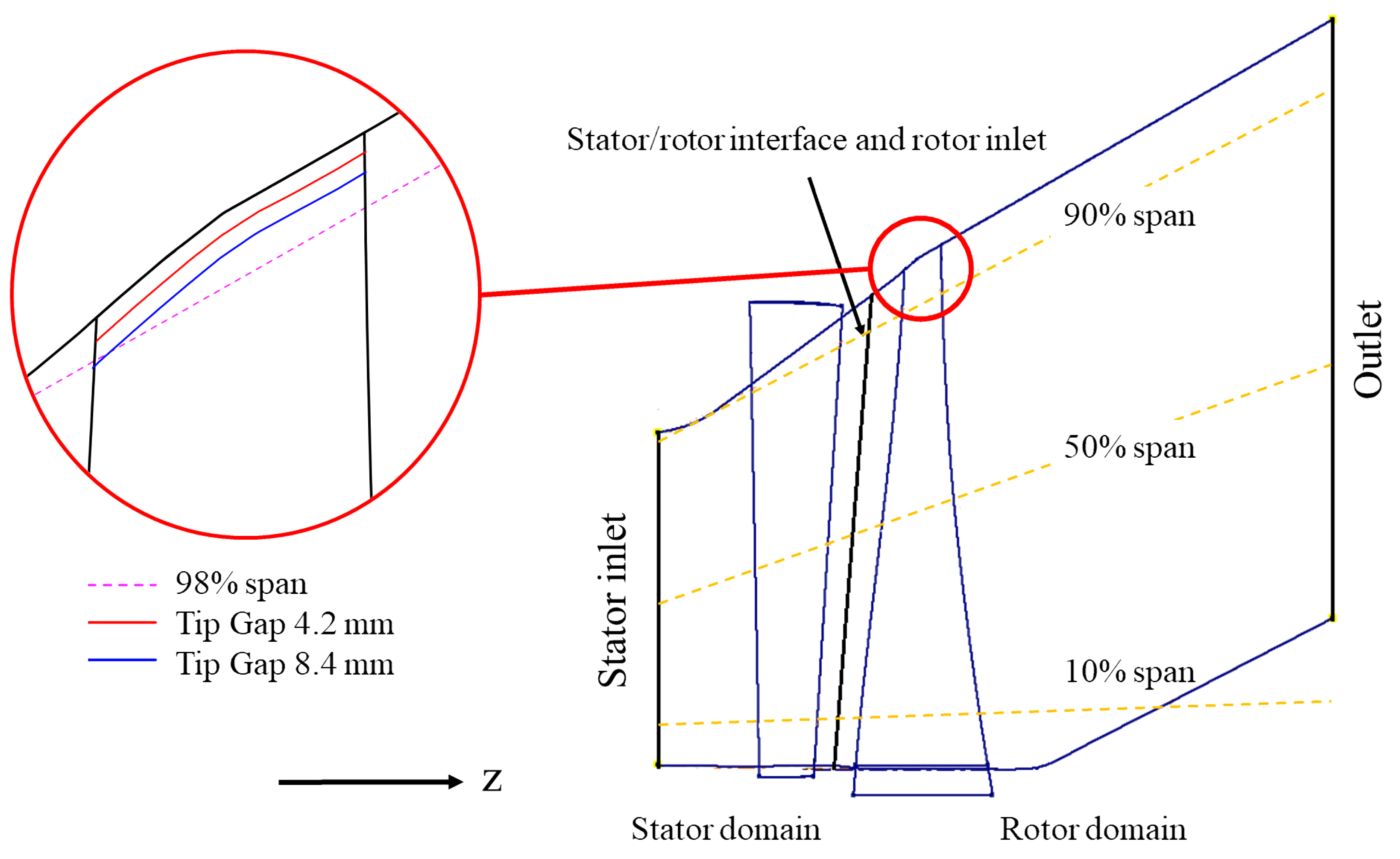
15]. A schematic figure of the KTH Steam Turbine Flutter Test Case and the definition of span surfaces are shown in Figure 1. The diffuser in the original design was included in the rotor computation domain to extend the fluid domain and reduce the influence of acoustic reflection at the outlet boundary [16]. The geometry and boundary conditions of the KTH Steam Turbine Flutter Test Case are available online [17]. The rotor rotated at 3000 rpm, and the average length of the rotor blade was 920 mm. A high stagger angle of 67 degrees presented near the tip of the rotor blade. The designed working point [15] was applied in this study. The average isentropic Mach number at the rotor exit was 1.12, and the flow at tip region was transonic. In conclusion, the test case had representative geometrical parameters and flow-field characteristics of modern steam turbines.
The blade material was assumed to be 17PH4 high strength steel in the modal analysis, the properties of which are shown in Table 1. The first blade-dominated bending mode of the KTH Steam Turbine Flutter Test Case was applied in the flutter analysis, as shown in Figure 2, which has been verified to be aeroelastically unstable at this working point [8].
The modal frequency of the first flap mode was 92.953 Hz, and therefore, the corresponded reduced frequency was about 0.2. The reduced frequency is a non-dimensional parameter that describes the level of unsteadiness, which is computed by Equation (3):
ω * = ω c V r e f = 2 π f c V r e f
where f is the modal frequency, c is the chord length, and V r e f is the average relative velocity at the turbine exit. The Durham steam turbine test case was designed based on aerodynamic considerations, but not structural dynamics, and as a result, the strength of the rotor blade was insufficient. The reduced frequency of the first bending mode was lower than that of a typical industry steam turbine. To build a representative real-scale steam turbine flutter test case, the reduced frequency was modified as 0.3 in the KTH Steam Turbine Flutter Test Case. The modified modal frequency calculated by Equation (3) equaled 132.08 Hz. The maximum blade vibration amplitude was set as 2 mm, which was 1.225% of chord length at the blade tip.
Five rotor models based on the original geometry are studied in this paper: one of them was set as no tip clearance, and the other four had different tip gap heights, as shown in Table 2. The blade tip surface was designed to be parallel to the shroud surface, as revealed in Figure 1. The computational meshes for the fluid domain of the five models were generated by TurboGrid. TurboGrid uses a non 1:1 mesh interface to connect the meshes from the pressure and suction side in the tip clearance. The number of mesh nodes and layers used in the spanwise direction in the tip clearance after mesh independence verification [18] is also presented in Table 2. The average y-plus of the cell height on the walls was around 20 to meet the requirement of the automatic turbulence wall function. Representative slices of the mesh in the fluid domain are revealed in Figure 3.

4. Results

The influence of tip clearance flow on the stage performance is generally insignificant in last-stage steam turbines, for the tip gap height is much smaller than the span height [19]. For the analyzed model, the relative variation of aerodynamic characteristics with the tip gap height is shown in Figure 4. A negative effect on the turbine efficiency was shown when the tip gap height was larger than 2.5% of chord length. Compared with the no tip gap model, an 8.4-mm tip gap increased the mass flow rate by 0.6% and decreased the total to static isentropic efficiency by 1.9% at the studied working point. According to previous research [8], the tip clearance flow can have a more dominant impact on the flow field near the blade tip region. The influence of tip clearance flow on both blade loading and the aeroelastic stability is presented in the following sections, and the underneath mechanism of those variations will be presented in Section 5.

4.1. Tip Clearance Flow Effects on Blade Loading

The blade loading in the steady state at 80%, 90%, and 98% span of the rotor surface is shown in Figure 5. There exists an interaction between 98% span line and the blade tip of the tip gap 8.4-mm model, which is revealed in Figure 1. Therefore, the numerical results of the tip gap 8.4-mm model near the leading edge on the 98% span surface are missing. The distribution of pressure at 80% and 90% span was qualitatively similar for all five models, which is consistent with the previous research [8], that the tip clearance flow majorly influences the local flow field near the tip. With the increase of tip gap height, a decrease in surface pressure was shown at the whole pressure side and the aft side of the suction side on 80% and 90% span. On 98% span, a more significant unloading effect on the pressure surface was shown, and the pressure decreased in the most of suction side, but not near the blade leading edge. The mononucleosis variation in the loading on the pressure surface was due to the absorbing effect of the well-development tip clearance flow in the large tip gap size models.
Since the majority of aerodynamic work variation due to tip clearance flow in turbines occurs on the tip region of the blade suction side [8], the distribution of blade loading on the suction side of the blade is highlighted in Figure 6. The pressure on both the front and aft part of the blade suction side was decreasing with the increase of tip gap height, and the difference was not in a linear relationship with the tip gap height, according to Figure 5c. Specifically, there were three dominant regions of loading difference, as marked in Figure 5 and Figure 6: A: near the middle chord of the blade suction side, from 90% span to blade tip; B: the front half of suction surface, parallel to the shroud surface and close to blade tip; and C: the aft side of blade suction side above 90% span.

4.2. Tip Clearance Flow Effects on Steam Turbine Aeroelastic Characteristics

The tip clearance effects on the integrated aerodynamic damping coefficient at various IBPAs was firstly investigated, which is shown in Figure 7. The tip clearance flow showed a detectable impact on the aerodynamic damping, and the influence of tip clearance flow on aeroelastic stability was dependent on the analyzed IBPA. These characteristics are in agreement with previous research [3,4,8]. Since the aerodynamic damping coefficient at the least stable IBPA is most critical in the design of a turbine, the relationship between aerodynamic damping and tip gap height at the two unstable IBPAs is highlighted in Figure 8. The overall aerodynamic damping at the two unstable IBPAs monotonously increased with the tip gap height for the studied models. The increase of aerodynamic damping till the tip gap height equaled 5% of chord length is inconsistent with the previous analysis in low-speed turbines [2] or long last-stage steam turbines [7].
To investigate the difference caused by the tip clearance, the distribution of the integrated aerodynamic damping among spans at IBPA = −60° is presented in Figure 9. The majority of aerodynamic work was done at the top 40% span, while the variation of aerodynamic damping among models mainly occurred above 85% span. This phenomenon is also verified in the distribution of wall work density at 80%, 90%, and 98% span in Figure 10. From Figure 10, the majority of the wall work coefficient difference occurred on the blade suction surface. Therefore, the distribution of local wall work density at the least stable IBPA (−60°) near the blade tip is presented in Figure 11 to analyze the underlying physical mechanism.
The location of the wall work coefficient variation can also be divided into three regions, corresponding to the three regions of blade loading variation presented in Figure 6. Compared with the no tip gap model, the tip clearance flow increased the aeroelastic stability in Regions A and C, while the wall work coefficient in Region B transformed from negative to positive. The strength of the three phenomena increased with the tip gap height for the five models. The underlying mechanism behind the differences observed will be discussed in the next section.

5. Discussion

To understand the tip clearance effects on both the steady and unsteady flow field, the flow structure in the tip region was firstly investigated in both the radial and circumferential direction. The Schlieren figure on 98% of the span surface presented in Figure 12 shows the development of tip clearance vortices in the blade-to-blade direction, as well as the interaction between tip clearance vortex and shocks. The development of tip clearance vortex in the radial direction is presented in Figure 13, which is the contour of the Mach number, as well as the vector of the velocity component at 80% axial chord from the leading edge of the rotor blade.
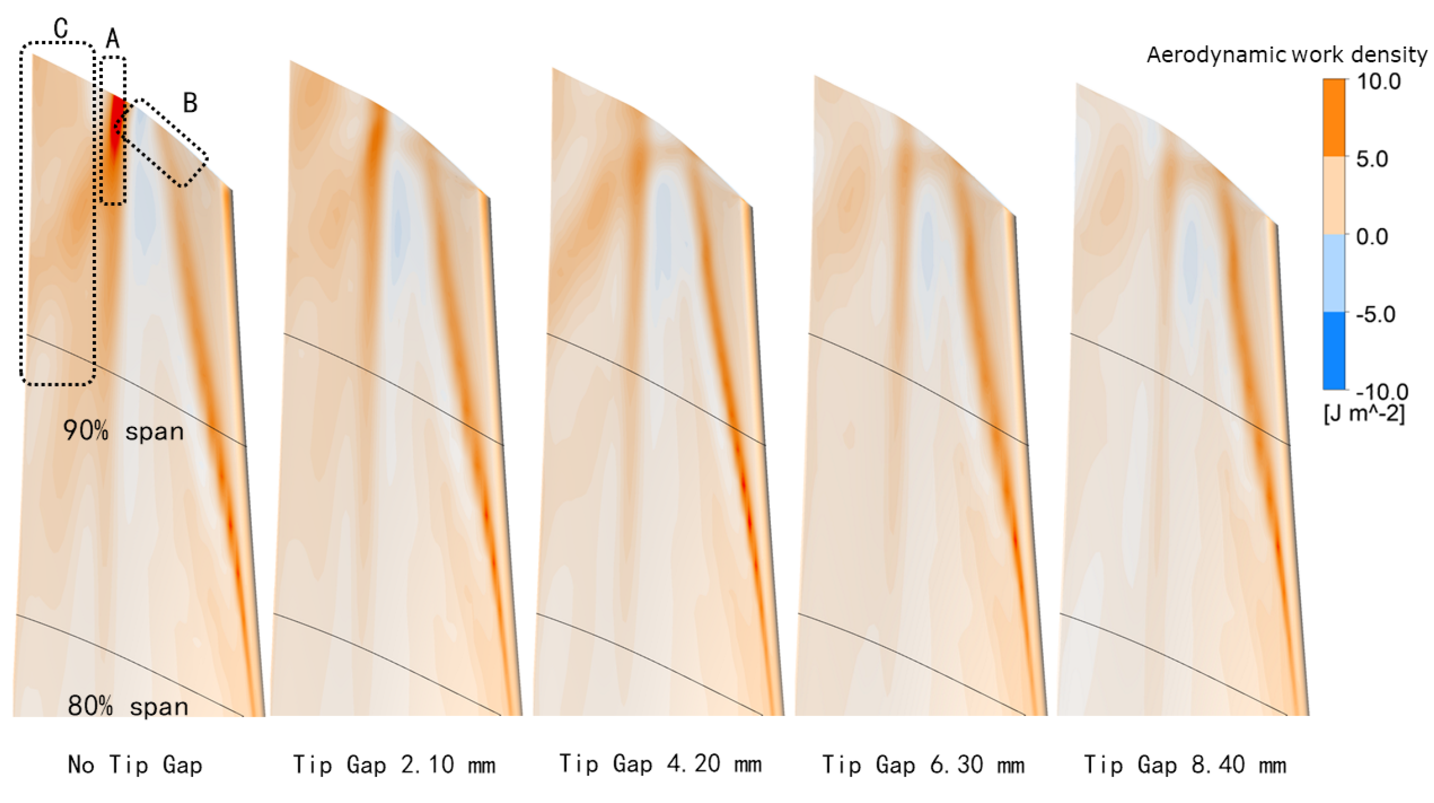
In the no tip gap model, the shock from the neighbor blade trailing edge impinged on the suction surface, and therefore, a clear reflection on the blade is shown in Figure 12. The influence of that shock was more alleviated with the increase of the strength of the tip leakage vortex. The interaction between the tip clearance flow and shock influenced the blade loading on the suction side near the mid-chord, as presented by Region A in Figure 6. Meanwhile, the oscillation of shock is also a source of unsteady aerodynamic force, as discussed in [6]. The reduction of impinging shock strength significantly decreased the amplitude of unsteady pressure in Region A, which reacts as a stabilization effect at the least stable IBPAs in Figure 10c and Figure 11. Although a strong influence on aerodynamic force was caused by this phenomenon, the interaction between tip leakage vortex and the impinging shock from adjacent blade cannot be resolved in the analysis of subsonic turbomachines.
From Figure 13, the tip leakage vortex is rotated in the clockwise direction (observed from the trailing edge side), and the local Mach number is relatively lower in the center of vortices. The core of the tip leakage vortex showed a trend of moving away from the blade suction surface, as well as the shroud when the tip gap height was increasing, which is also verified in Figure 12. The increase of flow speed due to tip leakage vortices reduced the pressure among the vortex trajectories, as shown in Region B of Figure 6. Due to the motion of the blade tip, the core of the tip leakage vortex oscillated at the same frequency as blade vibration [19], and the periodical pressure variation among the vortex trajectories produced extra aerodynamic work on the blade suction surface. The extra aerodynamic work presented a destabilizing effect because of the negative phase angle difference between the vortex motion and the blade motion, and the magnitude of the aerodynamic work increased with the strength of the tip leakage vortex. This phenomenon resulted in an increase of the wall work coefficient in Region B of Figure 10c and Figure 11, which was also found in previous research of low-speed turbine cascades [2].
Besides the flow field near the blade tip, the flow field within the top 10% of span height was also influenced by the tip leakage vortex when the tip gap height exceeded a certain value, such as 4.2 mm for the analyzed test case. The well-developed tip leakage vortex in the model with relative large tip gaps accelerated the flow above 90% span in the radial direction compared with the models with no tip clearance or with a small tip gap height, as shown in Region C of Figure 13 and Figure 14. The impact on flow field not only induced a variation in steady blade loading on the aft side of the suction surface (Region C in Figure 6), but also decreased the amplitude of unsteady pressure during blade vibration. The magnitude of positive aerodynamic work in Region C at the least stable IBPAs was thus reduced. The stabilizing effect was present in the models with large tip gap heights, as shown in Figure 10b,c and Figure 11. The increase of radial flow speed in the aft side of the blade suction side was possibly related to the increase of blade height among the flow directions in the tested model. For those steam turbines with a constant diameter in the tip region, the strength of this type of tip clearance effects on blade aeroelastic stability may be reduced.
In summary, the tip clearance effects on the steam turbine aeroelastic stability have both similar and different characteristics as those of low-speed turbines. The tip clearance effects on the aeroelastic stability of the analyzed model were dependent on the IBPA, which agrees with previous analyses [2,3,4,8]. Since the stabilizing effects located in Regions A and C at the least stable IBPA were produced by the reduction of unsteady pressure amplitude, the local aerodynamic work can only be decreased in magnitude instead of turning negative. Meanwhile, the destabilizing effects due to the oscillation of the tip leakage vortex (located in Region B) increased with the strength of the tip leakage vortex and tip gap height. Therefore, a continuous increase of the tip gap height will eventually decrease the aerodynamic damping at the least stable IBPA for the test case.
Due to the interaction between the tip clearance flow and the shock from the adjacent blade, the magnitude of the special gap height with maximum aerodynamic damping in this steam turbine model was much larger than that in low-speed turbine cascades [2]. However, this interaction phenomenon cannot be resolved in the analyses of low-speed turbines, and few experiments have been done on this mechanism in transonic cascades. Experimental analysis on the tip clearance effects on the turbomachinery flutter characteristics of a transonic cascade will be carried out at KTH in the near future.

6. Conclusions

The influence of the tip gap height on the aeroelastic stability of a realistic-scale last-stage steam turbine model was investigated in this paper. Five tip gap heights from 0–5% of chord length were analyzed. The numerical results showed that the global aerodynamic damping at the least stable inter-blade phase angle increased with the tip gap height till it equaled 5% of chord length. The tip clearance effects on blade aeroelastic stability were classified into three types of mechanisms.
The primary cause of the variation in total aerodynamic damping was the interaction between the tip clearance vortex and the trailing edge shock from the adjacent blade. Another mechanism was the acceleration of the flow near the aft side of the suction surface in the tip region due to the well-developed tip leakage vortex when the tip clearance height was greater than 2.5% chord. These two mechanisms reduced the magnitude of the local aerodynamic work coefficient at the least stable IBPAs and thus caused a stabilizing effect. Meanwhile, a negative influence on the aeroelastic stability was presented along with the tip clearance vortex trajectory due to the oscillation of tip leakage vortex during blade vibration. The destabilizing effect was enhanced with the increase of the strength of tip clearance vortex and the tip gap height.
As a result, a continuous increase of tip gap height will eventually decrease the aerodynamic damping at the least stable IBPA for the test case, i.e., there will be a special tip gap height that is most aeroelastically stable for the analyzed turbine. Due to the interaction between the tip clearance flow and the shock from the adjacent blade, the magnitude of the special gap height with maximum aerodynamic damping in this steam turbine model was much larger than that in low-speed turbine cascades; however, the interaction between tip leakage vortex and shocks cannot be resolved in analyses of low-speed turbines. Experimental analysis on the tip clearance effects on the turbomachinery flutter characteristics of a transonic cascade is planned to be carried at KTH.

Author Contributions

Conceived of and designed the numerical simulation, T.S. and P.P.; performed the simulation and analyzed the data, T.S. and M.Z.; writing, original draft preparation, T.S.; writing, review and editing, M.Z., P.P., and A.H.; supervision, P.P. and A.H.

Funding

This work is supported by the Special Funds of the Foshan Technology Innovation Team of China (No. 2016lt100123).

Conflicts of Interest

The authors declare no conflict of interest.

Abbreviations

The following abbreviations are used in this manuscript:
bblade height
cblade chord length
fmodal frequency
h m a x maximum blade vibration amplitude
nnodal diameter
n vector normal to surface element
Nnumber of blades
p r e f reference pressure
p i imaginary component of the unsteady pressure
Waerodynamic work coefficient
W a e r o aerodynamic work done to the blade per blade oscillating period
α h m a x / c
σ inter-blade phase angle
Ξ aerodynamic damping coefficient
ω angular frequency; natural frequency
ω * reduced frequency
AETRAeroelasticity Test Rig
CFDcomputational fluid dynamics
IBPAinter-blade phase angle
KTHKungliga Tekniska Högskolan (Royal Institute of Technology)
RPMround per minute
URANSunsteady Reynolds-averaged Navier–Stokes

References

  1. Bell, D.; He, L. Three Dimensional Unsteady Flow for an Oscillating Turbine Blade and the Influence of Tip Leakage. In ASME 1998 International Gas Turbine and Aeroengine Congress and Exhibition; American Society of Mechanical Engineers: Stockholm, Sweden, 1998. [Google Scholar] [Green Version]
  2. Huang, X.; He, L.; Bell, D.L. Effects of tip clearance on aerodynamic damping in a linear turbine cascade. J. Propul. Power 2008, 24, 26–33. [Google Scholar] [CrossRef]
  3. Glodic, N.; Vogt, D.; Fransson, T. Influence of Tip Clearance Modelling in Predictions of Aeroelastic Response in an Oscillating LPT Cascade. In Proceedings of the ISUAAAT 13, Tokyo, Japan, 11–14 September 2012. [Google Scholar]
  4. Teixeira, M.A.M.; Petrie-Repar, P.; Kameyama, S. Tip Clearance Influence on Aeroelastic Stability of an Axial Turbine Blade Row. In Proceedings of the ISUAAAT 14, Stockholm, Sweden, 8–11 September 2015. [Google Scholar]
  5. Besem, F.M.; Kielb, R.E. Influence of the Tip Clearance on a Compressor Blade Aerodynamic Damping. J. Propul. Power 2016, 33, 227–233. [Google Scholar] [CrossRef]
  6. Fu, Z.; Wang, Y.; Jiang, X.; Wei, D. Tip Clearance Effects on Aero-elastic Stability of Axial Compressor Blades. J. Eng. Gas Turb. Power 2015, 137, 012501. [Google Scholar] [CrossRef]
  7. Huang, X. Three-Dimensional Unsteady Flow in the Oscillating Turbine Blade Row. Ph.D. Thesis, Durham University, Durham, UK, 2006. [Google Scholar]
  8. Sun, T.; Petrie-Repar, P.; Qi, D. Investigation of Tip Clearance Flow Effects on an Open 3D Steam Turbine Flutter Test Case. In Proceedings of the ASME Turbo Expo 2017: Turbomachinery Technical Conference and Exposition; American Society of Mechanical Engineers: Charlotte, NC, USA, 2017. [Google Scholar]
  9. Carta, F.O. Coupled blade-disk-shroud flutter instabilities in turbojet engine rotors. J. Eng. Power 1967, 89, 419–426. [Google Scholar] [CrossRef]
  10. Marshall, J.; Imregun, M. A review of aeroelasticity methods with emphasis on turbomachinery applications. J. Fluids Struct. 1996, 10, 237–267. [Google Scholar] [CrossRef]
  11. Fuhrer, C.; Vogt, D.M. On the Impact of Simulation Approaches on the Predicted Aerodynamic Damping of a Low Pressure Steam Turbine Rotor. In ASME Turbo Expo 2017: Turbomachinery Technical Conference and Exposition; American Society of Mechanical Engineers: Charlotte, NC, USA, 2017. [Google Scholar]
  12. Daniel, S.; Frey, C. Time Domain Flutter Simulations of a Steam Turbine Stage Using Spectral 2D Non-Reflecting Boundary Conditions. In Proceedings of the ISUAAAT 15, University of Oxford, Oxford, UK, 24–27 September 2018. [Google Scholar]
  13. Hall, K.; Lorence, C.; Clark, W. Nonreflecting boundary conditions for linearized unsteady aerodynamic calculations. In Proceedings of the 31st Aerospace Sciences Meeting, Reno, NV, USA, 11–14 January 1993; p. 882. [Google Scholar]
  14. Petrie-Repar, P.; Makhnov, V.; Shabrov, N.; Smirnov, E.; Galaev, S.; Eliseev, K. Advanced Flutter Analysis of a Long Shrouded Steam Turbine Blade. In ASME Turbo Expo 2014: Turbine Technical Conference and Exposition; American Society of Mechanical Engineers: Dusseldorf, Germany, 2014. [Google Scholar]
  15. Burton, Z. Analysis of Low Pressure Steam Turbine Diffuser and Exhaust Hood Systems. Ph.D. Thesis, Durham University, Durham, UK, 2014. [Google Scholar]
  16. Sun, T.; Hou, A.; Zhang, M.; Petrie-Repar, P. Detached-Eddy Simulation Applied to Aeroelastic Stability Analysis in a Last-stage Steam Turbine Blade. J. Turbomach. 2019. to be published. [Google Scholar]
  17. Petrie-Repar, P.; Sun, T. 3D Steam Turbine Flutter Test Case. Available online: https://www.kth.se/en/itm/om/organisation/institutioner/energiteknik/forskningsavdelningar/kraft-varme/ekv-researchgroups/turbomachinery-group/aeromech-test-cases/3d-steam-turbine-flutter-test-case (accessed on 23 March 2018).
  18. Qi, D. Establishment of an Open 3D Steam Turbine Flutter Test Case. Master’s Thesis, KTH Royal Institute of Technology, Stockholm, Sweden, 2016. [Google Scholar]
  19. Sun, T. Improved Flutter Prediction for Turbomachinery Blades with Tip Clearance Flows. Ph.D. Thesis, KTH Royal Institute of Technology, Stockholm, Sweden, 2018. [Google Scholar]
Figure 1. Schematic figure of the steam turbine model with span lines and the location of the rotor blade tip.
Applsci 09 01213 g001
Figure 2. The first flap mode shape of the KTH Steam Turbine Flutter Test Case magnified by a factor of fifty. LE: the leading edge; TE: the trailing edge.
Applsci 09 01213 g002
Figure 3. Fluid mesh: (a) blade surface and hub and (b) blade shroud.
Applsci 09 01213 g003
Figure 4. Normalized difference in mass flow and total to static isentropic efficiency of the five rotor models.
Applsci 09 01213 g004
Figure 5. Blade loading in steady state at (a) 80%, (b) 90%, and (c) 98% span for the five studied models; the abscissa is the ratio of chord coordinates to the length of the chord, in which −1–0 indicate the trailing edge to the the leading edge on the suction surface and 0–1 indicate the leading edge to the trailing edge on the pressure surface.
Applsci 09 01213 g005
Figure 6. Blade loading in the steady state on the suction side of the rotor near the tip.
Applsci 09 01213 g006
Figure 7. Aerodynamic damping versus IBPA with various tip gap heights.
Applsci 09 01213 g007
Figure 8. Aerodynamic damping versus tip gap height at the two unstable IBPAs.
Applsci 09 01213 g008
Figure 9. Aerodynamic damping versus span with various tip gap heights when IBPA = 60   deg .
Applsci 09 01213 g009
Figure 10. Distribution of the wall work coefficient at (a) 80%, (b) 90%, and (c) 98% span; the abscissa is the ratio of chord coordinates to the length of chord, and −1–0 indicate the trailing edge to the the leading edge on the suction surface, while 0–1 indicate the leading edge to the trailing edge on the pressure surface.
Applsci 09 01213 g010
Figure 11. Distribution of the aerodynamic work coefficient on the suction side of rotor near the tip when IBPA = 60   deg .
Applsci 09 01213 g011
Figure 12. Schlieren figure on 98% of the span surface. The flow direction is from the left to the right.
Applsci 09 01213 g012
Figure 13. Mach number contour and the vector of velocity at 80% axial chord of the rotor. The suction side of the blade is located on the right side.
Applsci 09 01213 g013
Figure 14. Contour of radial velocity on the 92% span surface.
Applsci 09 01213 g014
Table 1. Material properties of the rotor blade.
Material PropertiesValue
Density7750 kg/m 3
Modulus of elasticity210 GPa
Poisson’s ratio0.3
Table 2. Geometry parameter of the five models.
ModelTip Gap Size/Chord (%)Tip Gap Size/Ave.Blade Length (%)Node Number in Rotor Domain (million)Number of Layers in the Tip Gap
No Tip Gap000.856-
Tip Gap 2.10 mm1.250.2281.3731
Tip Gap 4.20 mm2.500.4571.7261
Tip Gap 6.30 mm3.750.6851.7261
Tip Gap 8.40 mm5.00.9131.7261

