Article

Experimental Study on the Influence of an Extension Tube on the Evolution Process and Characteristic Parameters of a Gliding Arc

1
Science and Technology on Plasma Dynamics Laboratory, Air Force Engineering University, Xi’an 710038, China
2
Faculty of Economics, Trade and Tourism, Hefei Technology College, Hefei 238000, China
*
Authors to whom correspondence should be addressed.
Appl. Sci. 2019, 9(7), 1347; https://doi.org/10.3390/app9071347
Submission received: 25 February 2019 / Revised: 21 March 2019 / Accepted: 22 March 2019 / Published: 30 March 2019
(This article belongs to the Section Applied Physics General)

Abstract

:
The influence of the discharge cone size on the characteristic parameters of a rotating gliding arc, e.g., arc length, arc rotation frequency, and regeneration frequency was investigated when the grounding electrode was equipped with an extension tube. In addition, the effect of air flow rate (100~400 standard liter per minute, SLPM) on the characteristic parameters was also studied (with an extension tube, using a No. 5 discharge cone). The results showed that the disturbance of the outlet flow was intense without an extension tube, which led to the occurrence of the short-circuit regeneration of the gliding arc when the discharge gap was small, and the short-circuit regeneration of the gliding arc could be effectively avoided by adding an extension tube at the grounding end. The existence of the extension tube could significantly increase the arc length by up to 140 mm (250 SLPM, No. 3 discharge cone). The arc lengthening was mainly caused by the unilateral extension of the high voltage side, and the arc shape changed from a “C” to an “L” shape. This also reduced the regeneration frequency to one-quarter of the arc regeneration frequency without extending the tube. Without lengthening the tube, the arc could not achieve complete circumferential rotation. The arc distribution in the annular area between the anode and the cathode was discrete, and the arc distribution was extremely uneven. The existence of the extension tube made the arc rotate uniformly, and the maximum rotation frequency was 228 Hz. The influence of the air flow rate on arc length was mainly reflected in the small flow rate range. When the air flow rate was less than 200 SLPM, the arc length increased first, and then decreased with the increase of the air flow rate, reaching the maximum arc length of 143.6 mm at 150 SLPM. The arc frequency was positively correlated with the air flow rate, but the rotation frequency increased faster than the regeneration frequency: when the flow rate was 150 SLPM, the gliding arc rotated one circle in a tensile fracture period; when the flow rate reached 400 SLPM, the gliding arc rotated two circles in a tensile fracture period.

1. Introduction

Rotary detonation engine (RDE) is a new type of cycle power system that has a thermal cycle efficiency about 30% higher than that of an aero-turbine engine with isobaric combustion and can work continuously after ignition and provide stable thrust. It has broad application prospects in near space high-speed vehicles and so on [1,2,3]. At present, the detonation of a kerosene-air mixture faces prominent problems such as the slow evaporation of kerosene atomization [4,5], poor mixing effect, high ignition energy [6], and low chemical reaction rate. Auxiliary initiation methods such as hydrogen doping [7,8], oxygen supplementation [9,10], and preheating [11] are not suitable for equipping aircraft in service. Enhancing the activity of the kerosene-air mixture through fuel pyrolysis is expected to reduce the initiation energy and achieve the stable propagation of a detonation wave. Therefore, it is of great significance to solve the problem of kerosene-air detonation.
In the field of plasma fuel pyrolysis, a large number of studies have been carried out on hydrogen preparation and solid waste pyrolysis [12,13]. In addition, ethers, alcohols [14], methane [15], gasoline, diesel, macromolecular hydrocarbons [16], and other related fuel pyrolyses have also been carried out. With the development of the plasma form from the early arc thermal plasma to the present dielectric barrier discharge, corona, surface wave, and other cold plasma [17,18], gliding arc discharge and other efficient plasma methods have also been developing, and good results have been achieved in hydrogen production by cracking hydrocarbons such as trimethylpentane, tridecane, hexadecane, and diesel oil [19,20,21].
Gliding arc has a potential high electron density and can operate at atmospheric pressure [22,23], which makes it stand out from most non-equilibrium plasma. Kong et al. studied the high-power gliding arc driven by turbulent gas flow using a combination of optical and electrical diagnostics. According to the discharge phenomena, the gliding arc discharge was divided into two types: the glow type and spark type, which depended on the air flow rate and input power. In addition, it was found that the short circuit phenomenon would occur due to arc distortion and folding, and the local re-ignition phenomenon would also occur due to the increase of the internal impedance of the plasma stream column. Turbulence affected the gliding arc discharge by controlling the large-scale eddy to cause a short circuit and a small-scale eddy to cause local re-ignition [24]. Korolev et al. studied the gliding arc discharge with typical geometry under atmospheric air inflow and the discharge current was maintained at a relatively low level (0.2 A). The discharge started at spark breakdown, where the gap between the electrodes was very small, and then changed to a glow discharge. In the later stage, the flow column began to move between the electrodes under the action of air flow. The typical cathode-voltage-drop value in this regime was estimated to be about 300 V, an average electric field in the positive column plasma was 700–800 V/cm, and the neutral-particle temperature in the negative glow region was T~1100 K [25]. Gangoli et al. studied the rotating gliding arc discharge controlled by unidirectional Lorentz force. In this way, the plasma could not further elongate or disappear, and the electrical parameters could be accurately controlled. The effects of current on plasma motion, the presence of an ‘overshooting’ regime, voltage characteristics, and rotational and vibration temperatures at atmospheric pressure were introduced [26]. Zhang et al. studied a DC rotary gliding arc reactor at atmospheric pressure and found that there were two different motion patterns in air and N2. The time-resolved arc voltage signal showed three motion modes of the gliding arc: the arc restrike mode, takeover model, and combined models. The difference between these motion modes depended largely on the composition of the working gas and gas flow rate [27]. In addition, the physical characteristics of a gliding arc discharge reactor driven by a combination of magnetic and tangential airflow were analyzed by this research team. It was found that when air was used as the working gas, double arcs occurred at lower magnetic flux density (200 G). At a higher flux density (1000 G), the gliding arc would not break. When using O2 as the working gas, the gliding arc breakdown voltage and sustain voltage were both very low, and the average power applied was lower than that of the other cases [28]. Zhu et al. recorded the plasma column and tracer particle dynamics process with two synchronous high-speed cameras and analyzed their 3D data, which provided a more realistic understanding of the arc convection cooling process [29]. In order to analyze the motion characteristics of a HVDC (high voltage direct current) gliding arc, Richard et al. designed a multi-shot camera with a very short exposure time and gave a simple two-dimensional theoretical model that could be used to determine the conductive radius and axial temperature [30]. Lin et al. compared the discharge characteristics of a DC gliding arc and three-phase AC gliding arc and found that the three-phase AC gliding arc had higher power and more uniform temperature distribution [31].
Our research group has carried out a variety of pyrolysis fuels using dielectric barrier discharge. In order to apply the gliding arc discharge to pyrolysis, the plasma region needs to be significantly improved. For this reason, it was proposed that an extension tube be installed on the gliding arc discharge structure to expand the plasma treatment area. At present, to our knowledge, there have been no reports on this aspect in the world.

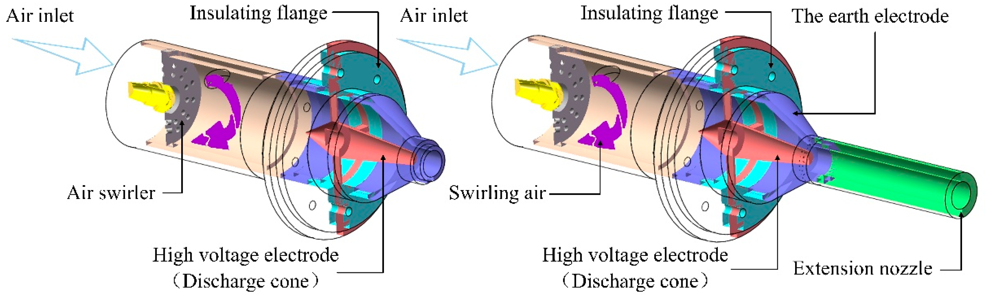
2. Experimental Approach

The experimental system is shown in Figure 1. An air compressor was used as the gas source. The volume of the gas storage tank was 1 cubic meter, the power was 15 kilowatts, and the maximum realizable steady air supply flow was 2400 SLPM. The air flow rate was monitored by a hot air flowmeter with a full range of 500 SLPM and a precision of 1.0%~1.5%. In the experiment, the AC power supply (CTD-1000Z, Nanjing Corona Lab) was used to supply the discharge tube, allowing a maximum voltage of 20 kV and rated power of 2000 W. The output high voltage of the power supply was connected to the outer side of the high voltage electrode flange of the discharge tube, and the convergent nozzle was grounded to realize the arc discharge between the discharge cone and the nozzle. The discharge parameters were measured using a P6015A high voltage probe and TCP0030A current probe and the data were collected with a MDO3024 digital oscilloscope. A Phantom-v2512 high-speed camera captured the discharge details. When the maximum resolution was 1024 × 1024, the maximum shooting speed was 20,000 frames per second. When the minimum resolution was used, the maximum shooting speed was 670,000 frames per second.
As shown in Figure 2, when air was supplied to the discharge chamber, it passed through a double-loop swirler first, which made the air flow rotate clockwise, seen from back to front. The external diameter of the swirler was 50 mm, and there were two circles of 3 mm diameter holes on the circumference of 28 mm and 38 mm in diameter. The number of holes in each circle was 12. The angle between the center axis of the hole at inner ring and the axis of the discharge tube was 35.94 degrees, and the angle between the center axis of the hole at the outer ring and the axis of the discharge tube was 44.52 degrees. Therefore, the degree of air swirl in the outer oblique hole was more severe than that in the inner oblique hole. The high-voltage electrode was arranged in the downstream direction 90 mm from the axial distance of the swirler. The high-voltage electrode was similar to a flange shape. The discharge cone was fixed on the central axis of the discharge tube through four fixed ribs with a width of 3 mm on the inside of the flange. The discharge cone can be replaced by a threaded connection. A diversion cone was set on the upstream side of the high-voltage electrode to minimize the influence of the presence of the high-voltage electrode on the flow field and pressure loss. The high voltage electrode flange was connected to a flange made of Teflon (PTFE) to realize the insulation of the grounding electrode and the swirler. The grounding electrode was a convergent nozzle with a minimum inner diameter of 15 mm. The discharge structure can be assembled to satisfy that the minimum cross section of the discharge cone end and convergent nozzle is on the same plane.
Six discharge cones with diameters of 5 mm to 10 mm and an interval of 1 mm were selected and numbered from small to large as No. 1 to No. 6. The discharge gap could be 5 mm, 4.5 mm, 4 mm, 3.5 mm, 3 mm, and 2.5 mm with the change of the size of the discharge cone. The total length of the extension tube used in the experiment was 100 mm (the condition of adding an extension tube is expressed in A, and the condition of not adding an extension tube is expressed in B). In the case of the 250 SLPM air flow, the arc evolution process of six kinds of discharge cones with and without extension tubes was photographed from the front and side, respectively. The influence of the extension tubes on arc length, arc rotation frequency, and regeneration frequency was studied. The effects of air flow rate (100–400 SLPM) on arc length, arc rotation frequency, and regeneration frequency were studied when the extension tube was added and the No. 5 discharge cone used. In this experiment, the parameters of the high-speed camera were: resolution of 512 × 512; shooting frequency of 30,000 fps; exposure time 15 μs, and storage time of 5 s. There were 38 experimental conditions in this paper. Each experimental condition was repeated three times, and the corresponding experimental data were averaged.

3. Results and Discussion

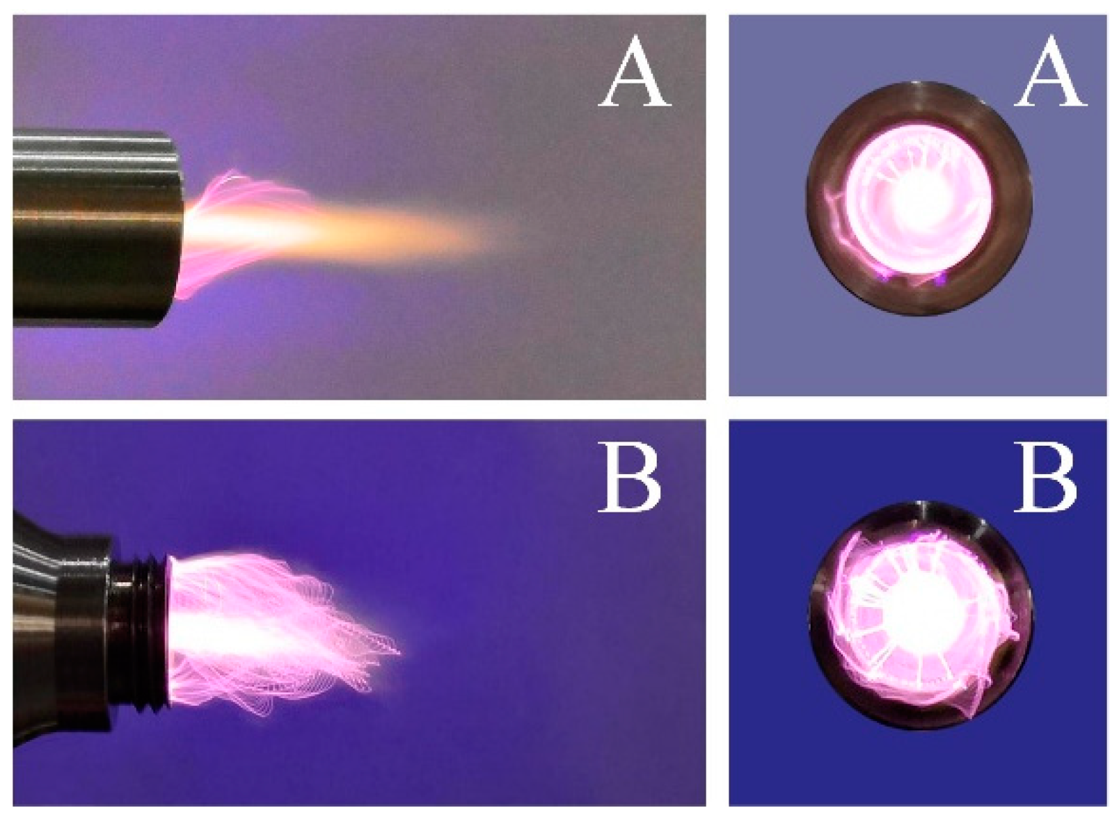
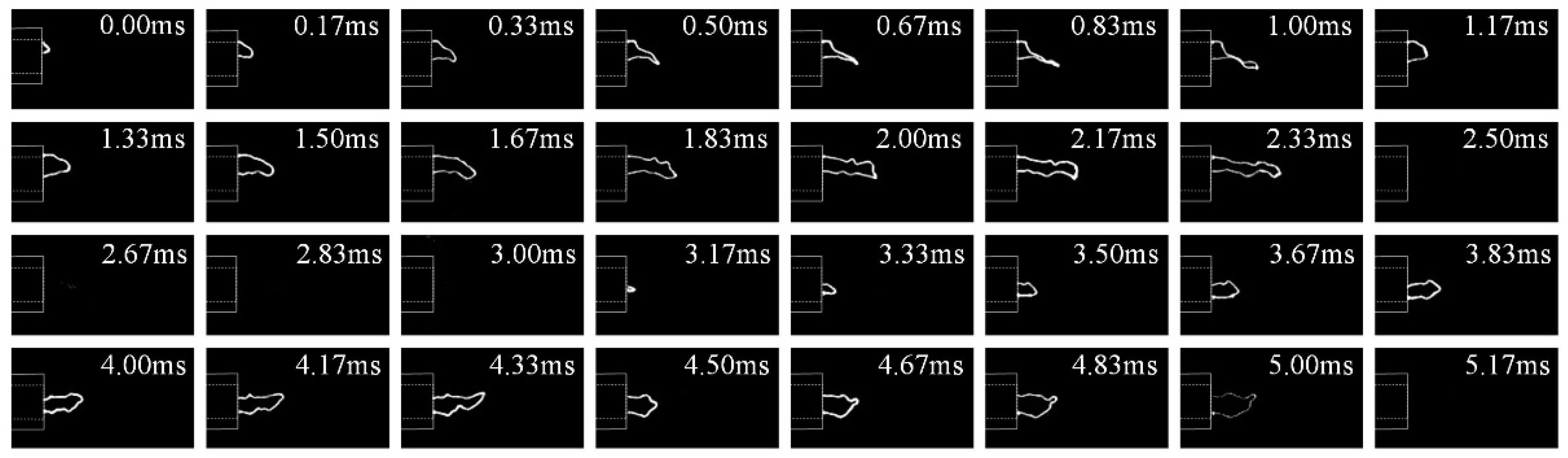
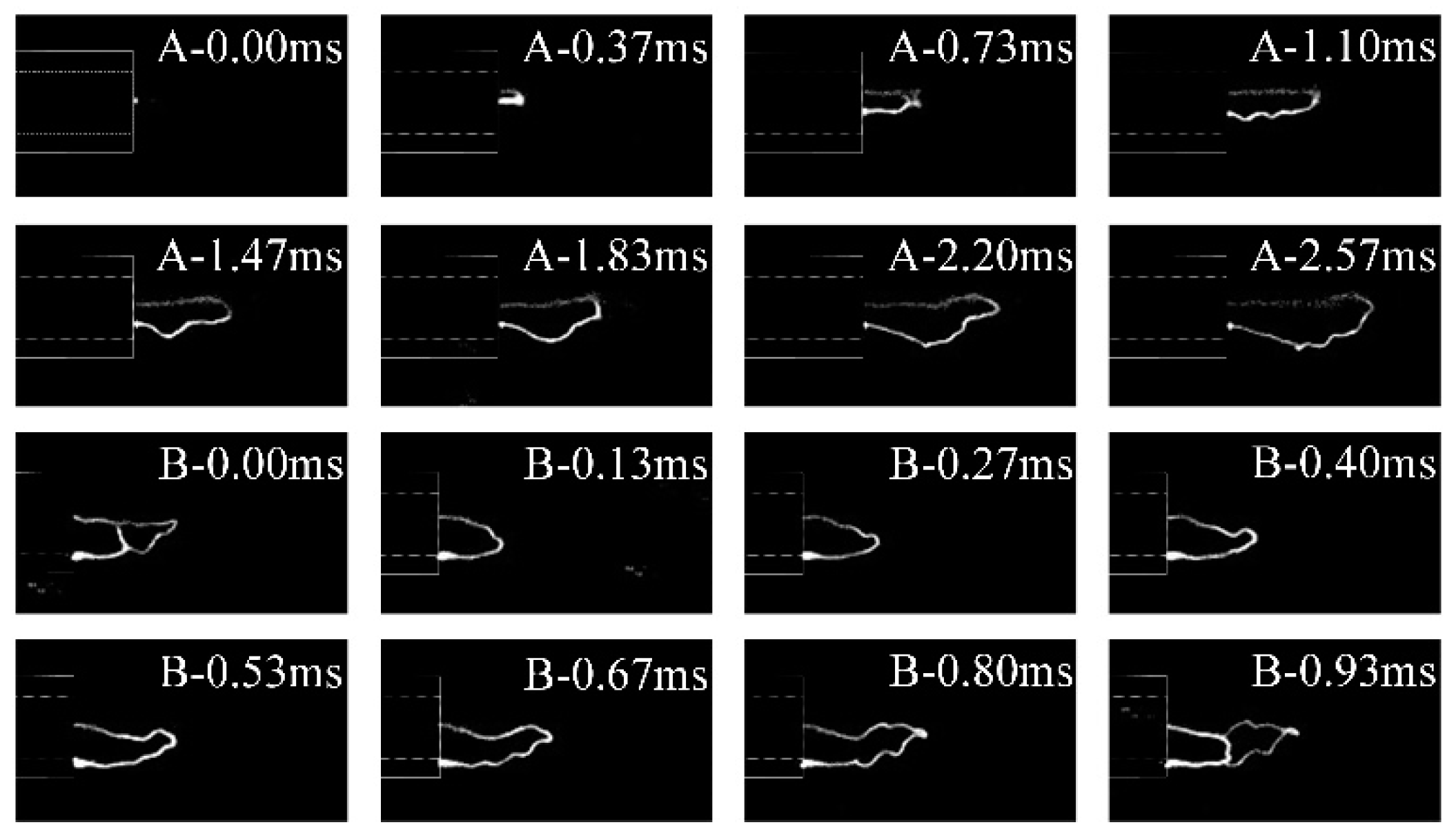
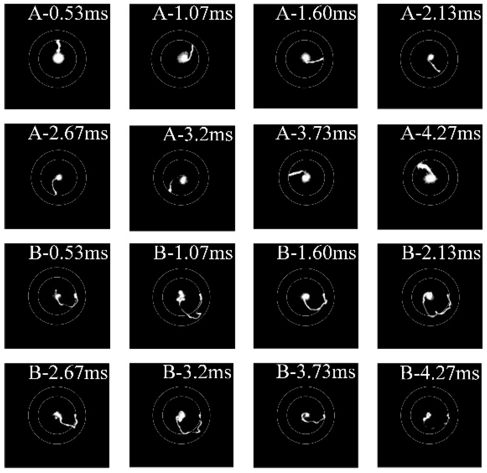
3.1. Arc Evolution Behavior

Figure 3 was taken with a digital camera with an exposure time of 10 milliseconds. Arc discharge images with and without an extension tube were taken from the front and side, respectively. It can be seen directly from the figure that the filamentary arc was very obvious without the extension tube, and the root of the contact between the arc and the discharge electrode was relatively fixed. The photo with the extension tube shows that the arc was more uniform and the rotation trend of the arc can be clearly seen from the photo taken from the front. At the same time, the side photographs show that the arc extended conically when the tube was lengthened, but without the extension tube, the plasma torch expanded at the exit, and the cone shape was not obvious.
Figure 4 shows the evolution of the gliding arc from the side view when the No. 5 anode cone without the extension tube was used for discharge. Two tension fracture cycles of the gliding arc are shown in Figure 4. It can be seen from the figure that the gliding arc began to reorganize at 1 ms and 4.33 ms, at which the head of the arc broke and was reconnected upstream and then stretched forward. Due to the small gap between the electrodes, the outlet velocity of air flow was higher, which made the disturbance of air flow at the center of the axis larger, and the gliding arc fluctuated violently on both sides of the axis, as shown in Figure 5. At the same time, the gliding arc rotated circumferentially and stretched forward under the influence of the rotating airflow. After the arc was elongated, the gap resistance of the discharge increased due to the arc path lengthening, and the required maintenance voltage increased sharply. Before the arc is stretched to the point where the loading voltage cannot maintain the arc and breaks, there is a space position in the process of arc evolution, which minimizes the normal distance on both sides of the gliding arc. At this point, the arc will break down and conduct, and then undergo a tensile fracture process. In this paper, this phenomenon is called the regeneration process of the gliding arc short circuit. This phenomenon is very common when the gap between the electrodes is small, which was the case of the No. 5 and No. 6 electrodes in this experiment.
The regeneration of the gliding arc short circuit can be effectively avoided by installing an extension tube at the grounding end. The two arc evolution situations of whether to install an extension tube or not were compared when using the No. 5 anode cone, as shown in Figure 6. In both cases, a complete gliding arc growth process was demonstrated. It can be seen that the new arcs developed from inside the extension tube to outside after the gliding arc prolongation and fracture with the addition of the extension tubes, and the probability of short-circuit regeneration was higher when there were no extension tubes. In this paper, the extension tube size was 100 mm. As the arc needs to break down and develop once again at the electrode gap after the gliding arc is extinguished, the arc undergoes a long stretch in the tube, which causes the single arc growth process to take a long time. Figure 6 shows that the arc stretching time was 2.57 ms when there was an extension tube, and 0.93 ms when there was no extension tube. The tangential velocity component will be generated by the air after the swirler. The closer the distance to the swirler, the more intense the air swirl. The discharge without the extension tube was greatly affected by the direction of the swirl air velocity; as shown in Figure 5, the arc fluctuated sharply. However, the extension tube had a rectification effect. Although the tangential velocity component still exists in the flow, the farther the flow is from the end of the electrode, the smaller the velocity component in the vertical axis direction, and the more stable the flow in the center of the extension tube. It can be seen from Figure 6 that the bending deformation of the central arc was larger without the extension tube, and after the installation of the elongation tube, the central arc basically presented a horizontal straight line, and did not fluctuate on both sides of the axis with the evolution of the gliding arc.

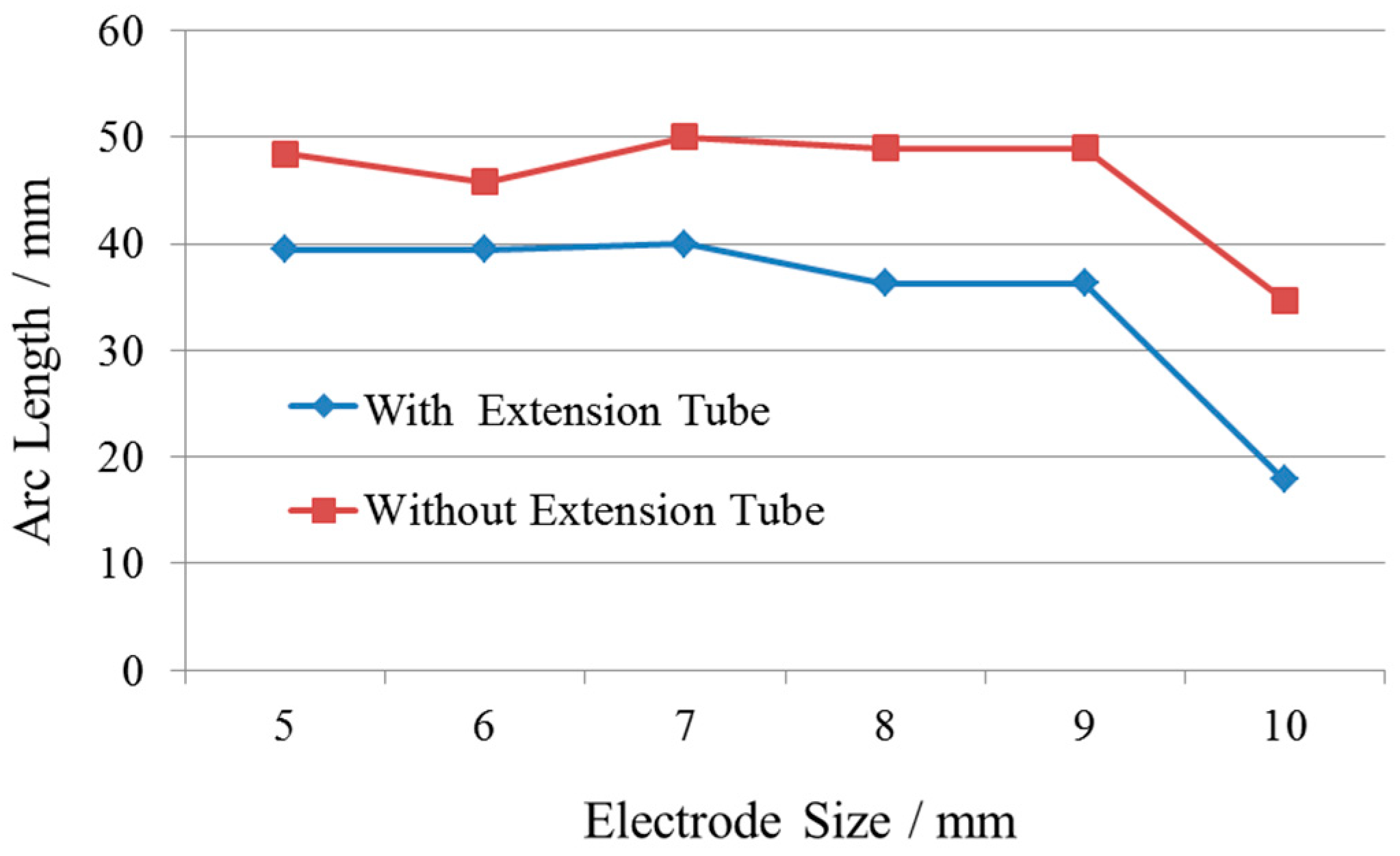
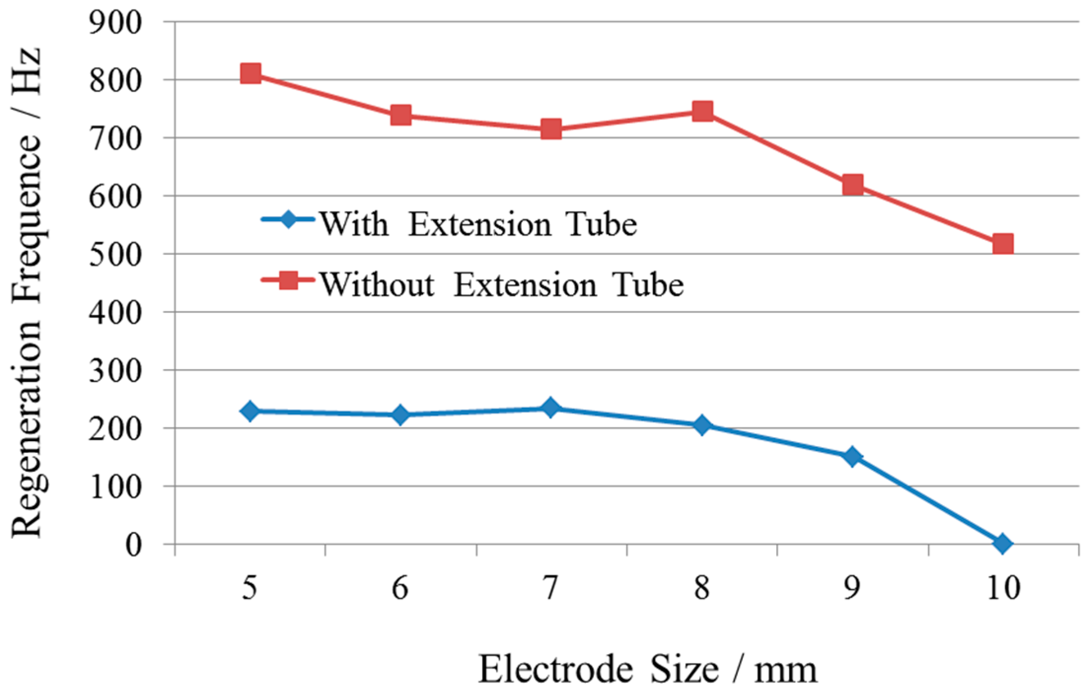
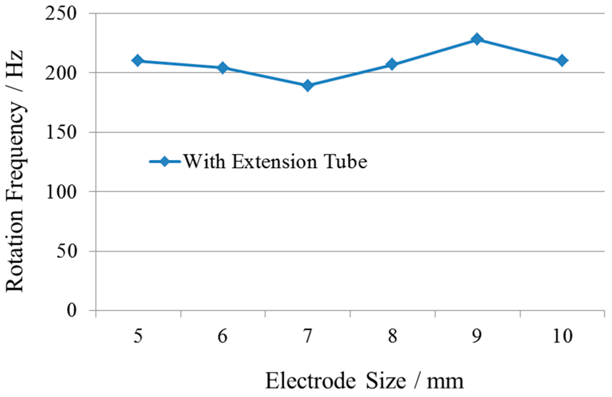
3.2. Effect of Nozzle on Arc Characteristic Parameters

In this paper, the data were processed frame by frame. First, the image was transformed into a gray format, and 150,000 pictures of storage time (5 s) were superimposed. Then, the data collected from the three repeated experiments under each condition were averaged, and finally, the arc length images under each condition (Figure 7) were obtained. It can be seen from the figure that the arc outside the nozzle exit was conical convergence and backward extension after adding the extension tube, while the plasma torch expanded first and then converged at the nozzle exit without the extension tube. This phenomenon was caused by the annular convergence channel that formed between the discharge cone at the nozzle exit and the grounding nozzle (in the case without the extension tube), and the air flow at different angular positions impacted on the central axis and collided with each other. The turbulence of flow at the nozzle outlet was severe, resulting in a pressure drop gradient along the radial direction from the center, resulting in a larger radial velocity of air flow, which made the arc bend outward. Finally, the plasma torch appeared to expand after leaving the nozzle outlet.
The effect of the extension tube on arc length is shown in Figure 8. On the whole, with the increase in the discharge cone diameter, the discharge gap decreases, and the arc length basically remains unchanged. When the discharge gap is less than the critical value, the arc length will be greatly reduced. For the discharge structure in this paper, the critical value was between 2.5 mm and 3.0 mm. The results showed that the average arc length without the extension tube was 10 mm longer than that with the extension tube. However, it should be considered that the arc length described in this paper was the arc length outside the nozzle. Considering that the arc will undergo a 100 mm extension tube when the nozzle is lengthened, it can be concluded that the length of the rotating gliding arc in the direction of the airflow can be effectively extended by lengthening the nozzle. It should be noted that the arc extension is only unilateral. Generally, the arc shape is “C”. The arc is divided by the farthest point to which the arc extends. The side connected with the high voltage electrode is called the high voltage side, and the side connected to the ground terminal is called the low voltage side. For the discharge with the extended tube in this paper, the arc extension was mainly attributed to the extension of the high voltage side. As the nozzle was a metal conductor, the extension tube acted as the grounding electrode, and the arc root of the low voltage side was directly connected with the end of the extension tube. From Figure 6, it can be seen that the brightness at the root of the low voltage side was enhanced and recorded as the cathode discharge point. At this time, the arc shape was similar to the slender “L” shape. When the discharge gap is less than the critical value, the breakdown voltage will decrease dramatically. After the air gap breakdown at the smallest gap between the discharge cone and grounding nozzle, under the action of the axial flow, the high voltage side extends backward, and the cathode discharge point moves downstream along the inner wall of the extension tube. When the arc is extended to the point where the required voltage to maintain the arc exceeds the breakdown voltage, the gliding arc will be extinguished and re-breakdown will occur at the minimum gap. In this case, the cathode discharge point has not yet moved to the end of the extension tube, and the high voltage side of the gliding arc has not been fully extended, which ultimately leads to a sharp reduction in the length of the plasma torch outside the nozzle.
The air gap breakdown-arc stretching-arc extinction is defined as a period, and the corresponding frequency is recorded as the frequency of the arc regeneration. The variation trend is similar to that of arc length. When the size of discharge cone is larger than a certain value, the frequency begins to decrease sharply. This can be seen from Figure 9 where the frequency of the arc regeneration without the extension tube was nearly four times as high as that with the extension tube. When the No. 6 discharge cone was used in assembling the extension tube, the regeneration frequency of the extension tube was recorded as 0 because the arc could not extend beyond the extended tube. Combined with Figure 8, it can be seen that the arc length of the No. 4 discharge cone and No. 5 discharge cone was the same, but the regeneration frequency was different. The regeneration frequency was more sensitive to the discharge spacing when the discharge cone became thicker and the gap spacing decreased, and the change trend obviously changed in advance. The possible reason is that as the gap becomes smaller, the equivalent resistance of the gap becomes smaller, and the breakdown of the gap becomes easier. In addition, once the air gap breaks down, the discharge current is much larger than that of the small discharge cone, which leads to a larger arc stiffness and a longer time-consuming process of arc stretching and deformation. Finally, although the arc length remains unchanged, the arc stretching period prolongs, that is, the regeneration frequency decreases.
For the circumferential rotation of the arc taken from the front, the case of the No. 5 discharge cone was used as an example. As shown in Figure 10, the arc rotated uniformly along the circumference when the extension tube was installed. From the perspective of the orthographic projection plane, the arc shape was basically along the radial direction, and the bending direction in the middle of the arc was the tangential direction of the air swirl. As the arc extended out of the extension tube, its cathode discharge point was located at the end of the extension tube. Therefore, in Figure 11, thick and bright spots appeared at the cathode discharge points. In the case of no extension tube, the position of the cathode discharge point was basically unchanged in a rotating period, and the arc bent sharply under the action of the rotating airflow. Combined with the analysis of the arc axial tension in Figure 4 above, it can also be seen that the arc was prone to short circuit regeneration, corresponding to 1.07 ms, 2.13 ms, and 3.2 ms in Figure 10, respectively. When the rotating gliding arc was applied to fuel pyrolysis, the discharge advantage with the extended tube was more obvious. On the one hand, due to the long arc stretching, the area of fuel treated by plasma will be greatly increased; on the other hand, because of the stable circumferential rotation of the arc, the pyrolysis fuel will be more uniform and stable.
Figure 11 visualizes the distribution of the rotating gliding arcs. Short-time Fourier transform was performed on the same pixel in all photos in each experimental condition to obtain the corresponding intensity value of the rotating principal frequency of each pixel, and finally the rotating gliding arc distribution cloud map was produced. The legend on the right side of Figure 11 shows the gray value, which represents the strength of the gliding arc. It can be seen from the figure that the distribution of the cathode discharge points was extremely non-uniform in the circumferential direction without the extension tube. When the No. 1 discharge cone was used, the breakdown position of the air gap was basically unchanged, and the cathode discharge point always stayed at P during shooting, which limited the area covered by the arc bending deformation. When using the No. 2, No. 5, and No. 6 discharge cones, although the arc coverage area was improved, the cathode discharge point had not been closed into a circle. The closure of the cathode discharge points of the No. 3 and No. 4 discharge cones was better, but it can be seen from Figure 11 that the arc distribution in the annular area between the anode and the cathode was discrete and not uniformly dispersed, which indicates that the arc distribution in the swept area was very uneven. In addition, the arc deformation was very severe due to the lack of the extension tube and rectification effect. The arc bending deformation developed to the outer side of the cathode ring, and the deformation was most obvious when the No. 3 discharge cone was used. In contrast, the uniformity of the arc distribution could be significantly improved by adding the extension tube. On the one hand, the circumferential distribution of the cathode discharge points was closed, on the other hand, the arc distribution between the electrodes was more uniform. Among them, the No. 5 discharge cone was the most prominent. Although some areas of the arc diffused beyond the boundary of the cathode circle, the overall arc brightness was higher, which further shows that the discharge current increased with the reduction of the electrode gap.
The arc rotation frequencies are compared in Figure 12. As the arc could not complete a full cycle rotation without the extension tube, only the rotation frequencies of the discharge with the extension tube were recorded. The results showed that the effect of the electrode gap on rotation frequency was very weak, but there was an optimal electrode. The rotational frequency of the No. 5 discharge cone was the highest, reaching 228 Hz/s. Combined with the analysis of arc length and regeneration frequency, the angle of the arc rotation was larger in a breakdown-stretching-quenching cycle when the No. 5 discharge cone was used. Therefore, the rotation frequency could be increased by sacrificing part of the regeneration frequency on the basis of ensuring a sufficient arc length.

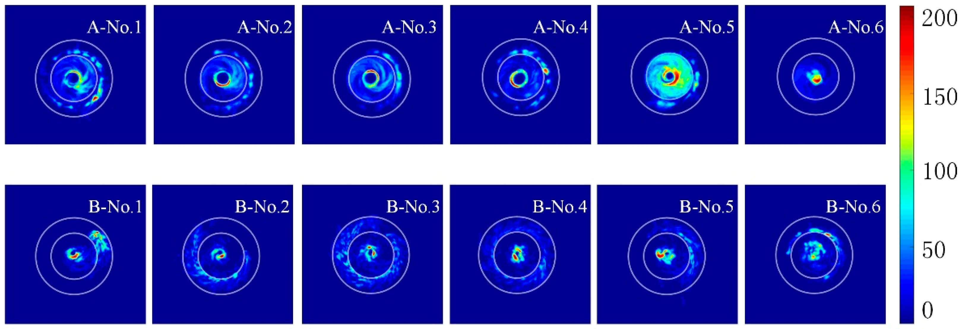
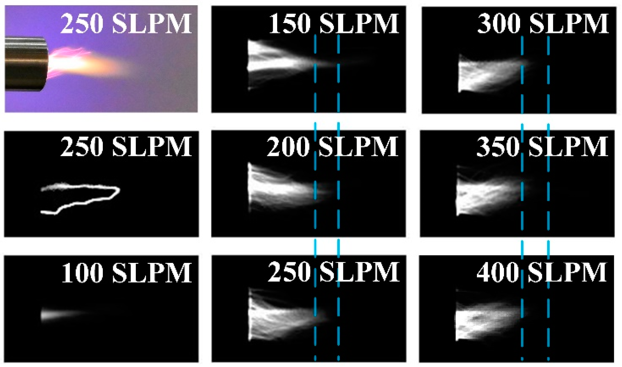
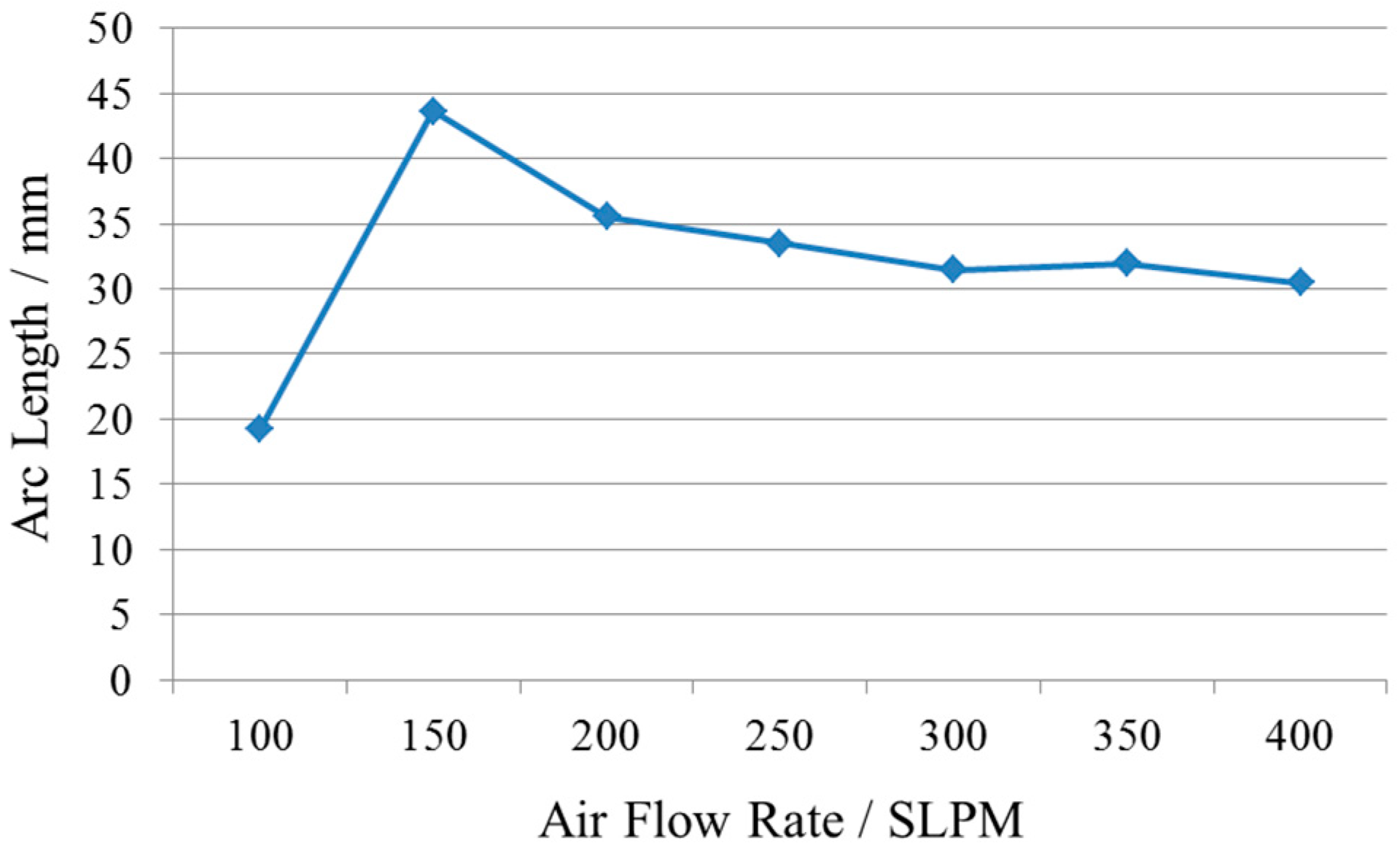
3.3. Effect of Air Flow on Arc Evolution

In this section, the effect of air velocity on the rotating gliding arc was analyzed. The discharge cones used in this section were all No. 5 discharge cones. In order to avoid the effect of accidental arc stretching on the arc length, the threshold value of gray value was set at 20 in the calculation program of the arc length. Pixels with a gray value less than 20 were not included in the calculation of the arc length. In order to visualize the difference in the arc lengths, two light blue dotted lines were drawn at the same position in the image, as shown in Figure 13. Obviously, the arc length increased significantly from 100 SLPM to 150 SLPM and decreased significantly from 150 to 200 SLPM. Then, with the increase of air flow rate, the arc length basically remained unchanged, as shown in Figure 14. When the air flow rate was greater than 200 SLPM, the arc length was between 30 mm and 35 mm, and the arc length did not change significantly with the change of air flow rate. The influence of the air flow rate on arc length was mainly reflected in the small flow range (100–200 SLPM).
Although only a small range of air flow had an effect on the arc length, the air flow had a significant effect on the rotation frequency and regeneration frequency of the rotating gliding arc in all experimental conditions. Figure 15 shows the effect of air flow on the two characteristic frequencies in one chart where it was obvious that the higher the velocity, the higher the frequency, but the change trend of the two characteristic frequencies was different. The rotating frequency was more sensitive to the increase of air flow, and its growth rate was much faster. From 150 SLPM, the ratios of rotation frequency to regeneration frequency were 1.07, 1.09, 1.63, 1.80, 1.75, and 2.0, respectively. Basically, when the flow rate was low (150~200 SLPM), the gliding arc rotated exactly one cycle during a tensile fracture period. With the increase of air velocity, the effect of air swirl was strengthened, and the number of gliding arc rotating circles increased gradually in a tensile fracture period. When 400 SLPM was reached, the gliding arc rotated two circles in a tensile fracture period.

4. Conclusions

The influence of the extension tube on the evolution of gliding arc was studied. The results showed that the rectifying action of the extension tube reduced the fluctuation of the gliding arc in the axial direction, reducing the wrinkle distortion of the gliding arc, thereby effectively reducing the short-circuit regeneration of the gliding arc. At the same time, the plasma torch was more concentrated and converged with the extension tube than when there was no extension tube. Since the extension tube was extended as the ground, the gliding arc length was greatly lengthened. This also resulted in a longer period of gliding arc tensile fracture, resulting in a reduction in the regeneration frequency of the gliding arc, which was about a quarter of that without the extension tube. Moreover, from the radial direction of the front view, the deformation of the gliding arc with the extension tube was smaller, and the circumferential distribution was more uniform than that without the extension tube. Our study changed the discharge gap by changing the discharge cone where it was found that the change in the gap had almost no effect on the gliding arc length under the same airflow. When the discharge gap was larger than a certain value, the length of the gliding arc was significantly reduced. Additionally, the influence of the discharge cone on regeneration frequency also had the same rule. At the same time, the discharge gap had a weak influence on the rotation frequency of the gliding arc, but an optimal gap existed. Air flow had a significant effect on the length of the gliding arc in the range of 100–200 SLPM. When the flow rate was greater than 200 SLPM, the effect was sharply reduced. At the same time, it was found that the rotation frequency and the regeneration frequency were more sensitive to air flow than the length of the gliding arc. Interestingly, the rotation frequency was about twice the regeneration frequency at 400 SLPM. In other words, the gliding arc can be rotated twice during a tensile fracture period.

Author Contributions

Writing—original draft preparation, S.X.; writing—review and editing, F.S.; investigation, X.Y.; data curation, Y.Z.; formal analysis, Y.G.

Funding

This research received no external funding.

Conflicts of Interest

The authors declare no conflict of interest.

References

  1. Zhu, Y.; Anand, V.; Jodele, J.; Knight, E.; Gutmark, E.J.; Burnette, D. Plasma-assisted rotating detonation combustor operation. In Proceedings of the 53rd AIAA/SAE/ASEE Joint Propulsion Conference, Atlanta, GA, USA, 10–12 July 2017. [Google Scholar] [CrossRef]
  2. Nakagami, S.; Matsuoka, K.; Kasahara, J.; Matsuo, A.; Funaki, I. Visualization of rotating detonation waves in a plane combustor with a cylindrical wall injector. In Proceedings of the 53rd AIAA Aerospace Sciences Meeting, Kissimmee, FL, USA, 5–9 January 2015. [Google Scholar] [CrossRef]
  3. Dyer, R.; Naples, A.; Kaemming, T.; Hoke, J.; Schauer, F. Parametric testing of a unique rotating detonation engine design. In Proceedings of the 50th AIAA Aerospace Sciences Meeting including the New Horizons Forum and Aerospace Exposition, Nashville, TN, USA, 9–12 January 2012. [Google Scholar] [CrossRef]
  4. Ghassemi, H.; Baek, S.W.; Khan, Q.S. Experimental study on evaporation of kerosene droplets at elevated pressures and temperatures. Combust. Sci. Technol. 2006, 178, 1669–1684. [Google Scholar] [CrossRef]
  5. Ra, Y.; Reitz, R.D. A vaporization model for discrete multi-component fuel sprays. Int. J. Multiph. Flow 2009, 35, 101–117. [Google Scholar] [CrossRef]
  6. Schauer, F.; Miser, C.; Tucker, C.; Bradley, R.; Hoke, J. Detonation initiation of hydrocarbon-air mixtures in a pulsed detonation engine. In Proceedings of the 43rd AIAA Aerospace Sciences Meeting and Exhibit, Reno, NV, USA, 10–13 January 2005. [Google Scholar] [CrossRef]
  7. Le Naour, B.; Falempin, F.H.; Coulon, K. MBDA R&T effort regarding continuous detonation wave engine for propulsion-status in 2016. In Proceedings of the 21st AIAA International Space Planes and Hypersonics Technologies Conference, Xiamen, China, 6–9 March 2017. [Google Scholar] [CrossRef]
  8. Kindracki, J. Experimental research on rotating detonation in liquid fuel–gaseous air mixtures. Aerosp. Sci. Technol. 2015, 43, 445–453. [Google Scholar] [CrossRef]
  9. Bykovskii, F.A.; Zhdan, S.A.; Vedernikov, E.F. Continuous spin detonation of fuel-air mixtures. Combust. Explos. Shock Waves 2006, 42, 463–471. [Google Scholar] [CrossRef]
  10. Schwer, D.; Kailas, K. Fluid dynamics of rotating detonation engines with hydrogen and hydrocarbon fuels. Proc. Combust. Inst. 2013, 34, 1991–1998. [Google Scholar] [CrossRef]
  11. Kailasanath, K. Liquid-fueled detonations in tubes. J. Propuls. Power 2006, 22, 1261–1268. [Google Scholar] [CrossRef]
  12. Chen, F.; Huang, X.; Cheng, D.G.; Zhan, X. Hydrogen production from alcohols and ethers via cold plasma: A review. Int. J. Hydrogen Energy 2014, 39, 9036–9046. [Google Scholar] [CrossRef]
  13. Ruj, B.; Ghosh, S. Technological aspects for thermal plasma treatment of municipal solid waste—A review. Fuel Process. Technol. 2014, 126, 298–308. [Google Scholar] [CrossRef]
  14. Burlica, R.; Shih, K.Y.; Hnatiuc, B.; Locke, B.R. Hydrogen generation by pulsed gliding arc discharge plasma with sprays of alcohol solutions. Ind. Eng. Chem. Res. 2011, 50, 9466–9470. [Google Scholar] [CrossRef]
  15. Zhang, H.; Du, C.; Wu, A.; Bo, Z.; Yan, J.; Li, X. Rotating gliding arc assisted methane decomposition in nitrogen for hydrogen production. Int. J. Hydrogen Energy 2014, 39, 12620–12635. [Google Scholar] [CrossRef]
  16. Taghvaei, H.; Jahanmiri, A.; Rahimpour, M.R.; Shirazi, M.M.; Hooshmand, N. Hydrogen production through plasma cracking of hydrocarbons: Effect of carrier gas and hydrocarbon type. Chem. Eng. J. 2013, 226, 384–392. [Google Scholar] [CrossRef]
  17. Samal, S. Thermal plasma technology: The prospective future in material processing. J. Clean. Prod. 2017, 142, 3131–3150. [Google Scholar] [CrossRef] [Green Version]
  18. Deminsky, M.; Jivotov, V.; Potapkin, B.; Rusanov, V. Plasma-assisted production of hydrogen from hydrocarbons. Pure Appl. Chem. 2002, 74, 413–418. [Google Scholar] [CrossRef]
  19. Babaritskii, A.; Bibikov, M.B.; Zhivotov, V.K.; Lysov, G.V.; Rusanov, V.D.; Cheban’kov, F.N.; Baranov, I.E.; Demkin, S.; Konovalov, G.M.; Moskovski, A.S.; et al. Partial hydrocarbon oxidation processes induced by atmospheric-pressure microwave-discharge plasma. High Energy Chem. 2004, 38, 407–411. [Google Scholar] [CrossRef]
  20. Matsui, Y.; Kawakami, S.; Takashima, K.; Katsura, S.; Mizuno, A. Liquid-phase fuel re-forming at room temperature using nonthermal plasma. Energy Fuels 2005, 19, 1561–1565. [Google Scholar] [CrossRef]
  21. Gallagher, M.J.; Geiger, R.; Polevich, A.; Rabinovich, A.; Gutsol, A.; Fridman, A. On-board plasma-assisted conversion of heavy hydrocarbons into synthesis gas. Fuel 2010, 89, 1187–1192. [Google Scholar] [CrossRef]
  22. Xin, T.; Gallon, H.J.; Whitehead, J.C. Dynamic behavior of an atmospheric argon gliding arc plasma. IEEE Trans. Plasma Sci. 2011, 39, 2900–2901. [Google Scholar] [CrossRef]
  23. Fridman, A.; Gutsol, A.; Gangoli, S.; Ju, Y.; Ombrello, T. Characteristics of gliding arc and its application in combustion enhancement. J. Propuls. Power 2008, 24, 1216–1228. [Google Scholar] [CrossRef]
  24. Kong, C.; Gao, J.; Zhu, J.; Ehn, A.; Aldén, M.; Li, Z. Effect of turbulent flow on an atmospheric-pressure AC powered gliding arc discharge. J. Appl. Phys. 2018, 123, 223–302. [Google Scholar] [CrossRef]
  25. Korolev, Y.D.; Frants, O.B.; Geyman, V.G.; Landl, N.V.; Kasyanov, V.S. Low-current “gliding arc” in an air flow. IEEE Trans. Plasma Sci. 2011, 39, 3319–3325. [Google Scholar] [CrossRef]
  26. Gangoli, S.P.; Gutsol, A.F.; Fridman, A.A. A non-equilibrium plasma source: Magnetically stabilized gliding arc discharge: I. Design and diagnostics. Plasma Sour. Sci. Technol. 2010, 19, 065003. [Google Scholar] [CrossRef]
  27. Hao, Z.H.A.N.G.; Fengsen, Z.; Xin, T.U.; Zheng, B.; Kefa, C.; Xiaodong, L. Characteristics of atmospheric pressure rotating gliding arc plasmas. Plasma Sci. Technol. 2016, 18, 473. [Google Scholar] [CrossRef]
  28. Zhang, H.; Li, X.D.; Zhang, Y.Q.; Chen, T.; Yan, J.H.; Du, C.M. Rotating gliding arc codriven by magnetic field and tangential flow. IEEE Trans. Plasma Sci. 2012, 40, 3493–3498. [Google Scholar] [CrossRef]
  29. Zhu, J.; Gao, J.; Ehn, A.; Aldén, M.; Li, Z.; Moseev, D.; Kusano, Y.; Salewski, M.; Alpers, A.; Gritzmann, P. Measurements of 3D slip velocities and plasma column lengths of a gliding arc discharge. Appl. Phys. Lett. 2015, 106, 044101. [Google Scholar] [CrossRef] [Green Version]
  30. Richard, F.; Cormier, J.M.; Pellerin, S.; Chapelle, J. Physical study of a gliding arc discharge. J. Appl. Phys. 1996, 79, 2245–2250. [Google Scholar] [CrossRef]
  31. Lie, L.; Bin, W.; Chi, Y.; Chengkang, W.U. Characteristics of gliding arc discharge plasma. Plasma Sci. Technol. 2006, 8, 653. [Google Scholar] [CrossRef]
Figure 1. Schematic diagram of gliding arc discharge experimental system.
Applsci 09 01347 g001
Figure 2. Schematic diagram of discharge device with or without extension tube.
Applsci 09 01347 g002
Figure 3. Arc discharge image taken by a digital camera (A: with extension tube; B: without extension tube).
Applsci 09 01347 g003
Figure 4. Arc tension fracture process (No. 5 electrode, no extension tube).
Applsci 09 01347 g004
Figure 5. The phenomenon of arc fluctuation near the central axis.
Applsci 09 01347 g005
Figure 6. Contrast of arc growth process with or without extension tube.
Applsci 09 01347 g006
Figure 7. Comparison of arc profiles with different discharge cones.
Applsci 09 01347 g007
Figure 8. Effect of discharge cone size on arc length.
Applsci 09 01347 g008
Figure 9. The influence of the discharge cone size on the regeneration frequency.
Applsci 09 01347 g009
Figure 10. Comparison of the development and evolution of the gliding arc circumferential rotation.
Applsci 09 01347 g010
Figure 11. Distribution uniformity of the rotating gliding arc under different experimental conditions.
Applsci 09 01347 g011
Figure 12. The effect of the electrode size on rotational frequency with the extension tube.
Applsci 09 01347 g012
Figure 13. Side photographs of the arc taken under different air flow rates.
Applsci 09 01347 g013
Figure 14. The influence of air flow rate on arc length (No. 5 discharge cone, with the extension tube).
Applsci 09 01347 g014
Figure 15. The influence of the air flow rate on the rotational frequency and regenerative frequency of the gliding arc (No. 5 discharge cone, with an extension tube).
Applsci 09 01347 g015

