Abstract
Massive hydraulic fracturing of vertical wells has been extensively employed in the development of low-permeability gas reservoirs. The existence of multiple hydraulic fractures along a vertical well makes the pressure profile around the vertical well complex. This paper studies the pressure dependence of permeability to develop a seepage model of vertical fractured wells with multiple hydraulic fractures. Both transformed pseudo-pressure and perturbation techniques have been employed to linearize the proposed model. The superposition principle and a hybrid analytical-numerical method were used to obtain the bottom-hole pseudo-pressure solution. Type curves for pseudo-pressure are presented and identified. The effects of the relevant parameters (such as dimensionless permeability modulus, fracture conductivity coefficient, hydraulic-fracture length, angle between the two adjacent hydraulic fractures, the difference of the hydraulic-fracture lengths, and hydraulic-fracture number) on the type curve and the error caused by neglecting the stress sensitivity are discussed in detail. The proposed work can enrich the understanding of the influence of the stress sensitivity on the performance of a vertical fractured well with multiple hydraulic fractures and can be used to more accurately interpret and forecast the transient pressure.
1. Introduction
Gas flow in porous media has recently attracted much attention and stimulated great interest in the development of oil and gas reservoirs [1,2,3,4,5,6,7,8,9,10,11,12,13,14,15]. In the past decades, many gas reservoirs with stress-sensitive permeability have been discovered and developed around the world. During the development process of stress-sensitive reservoirs, the continuously decreasing formation pressure leads to the decrease of the formation permeability. Therefore, it is critical to investigate the effect of the stress sensitivity of the permeability on the production. Recently, lots of models have been established to study the performance of various wells in stress-sensitive reservoirs [16,17,18].
On the other hand, in order to obtain economic benefit, hydraulic fracturing has been widely applied in the development of low-permeability gas reservoirs. A great variety of seepage models of vertical fractured wells have been proposed and the characteristic of pressure response has been studied in detail. Gringarten et al. [19] established a seepage model of a vertical fractured well with two symmetrical infinite-conductivity hydraulic fractures, which can be used to identify the linear flow. Later, by considering the effect of the fluid flow within the hydraulic fractures, a seepage model of a vertical fractured well with two symmetrical finite-conductivity hydraulic fractures was established [20,21], which can identify the bilinear flow. Some researchers pointed out the existence of two asymmetrical hydraulic fractures in practice and established some seepage models of vertical fractured wells with two asymmetrical hydraulic fractures [22,23,24,25,26,27]. In fact, massive hydraulic fracturing usually creates fractured network or several main hydraulic fractures near the wellbore instead of two symmetrical/asymmetrical hydraulic fractures [28,29,30,31]. Recently, seepage models of vertical fractured wells with multiple hydraulic fractures have received more attention. Shaoul et al. [32] proposed a numerical model of a vertical fractured well with multiple hydraulic fractures and investigated the pressure behavior of a vertical fractured well. Restrepo and Tiab [33] and Wang et al. [34] established semi-analytical models of a vertical fractured well with multiple infinite-conductivity hydraulic fractures. Ren and Guo [35] and Luo and Tang [36] proposed semi-analytical models of a vertical fractured well with multiple finite-conductivity hydraulic fractures. Compared with the pressure behavior of vertical fractured wells with two hydraulic fractures, the pressure response of vertical fractured wells with multiple hydraulic fractures is very complex. Although the effect of relevant parameters on the pressure response of vertical fractured wells with multiple hydraulic fractures has been studied, and the characteristics of the type of curves is not clearly understood. More important, little work has focused on vertical fractured wells with multiple hydraulic fractures in stress-sensitive gas reservoirs. In particular, the effect of relevant parameters on the error caused by neglecting the stress sensitivity has not been recognized clearly.
In this paper, we propose a seepage model of vertical fractured wells with multiple finite-conductivity hydraulic fractures. Type curves are identified and analyzed. The effects of relevant parameters on type curves and the error caused by neglecting the stress sensitivity are discussed in detail. This work can enrich the understanding of the influence of stress sensitivity on the performance of vertical fractured wells with multiple hydraulic fractures.
2. Physical Model
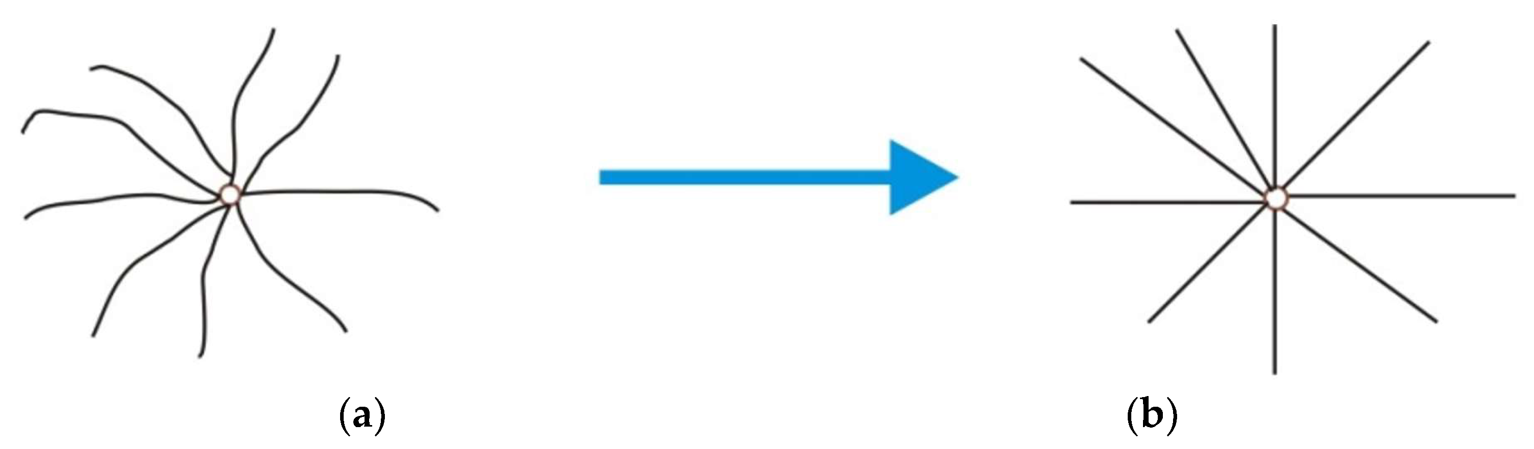
Complex geometry patterns of hydraulic fractures for vertical fractured wells can be described by the multiple-fracture model which is shown in Figure 1. Some assumptions of the present model are given as follows:

Figure 1.
Vertical fractured well with multiple hydraulic fractures and its model. (a) Complex geometry pattern, (b) Multiple fracture model.
(1) The gas reservoir is a homogeneous and laterally infinite formation with a constant thickness. The top and bottom boundaries of the gas reservoir are assumed to be impermeable.
(2) The finite-conductivity hydraulic fractures emanate from the wellbore in the horizontal plane (as shown in Figure 1b) and completely penetrate the formation in the vertical plane. The length of each hydraulic fracture may be different.
(3) The vertical fractured well produces only from the hydraulic fractures and the production rate of the vertical fractured well keeps constant.
(4) The permeabilities of both the reservoir and hydraulic fractures change with pressure.
(5) The gas reservoir has a constant temperature and uniform initial pressure.
3. Mathematical Model
A semi-analytical model of vertical fractured well with multiple finite-conductivity hydraulic fractures in stress-sensitive gas reservoirs is established and solved by incorporating various methods and techniques. The nomenclatures of the present model are listed in Appendix A. The flow chart of solution methodology is shown in Figure 2.
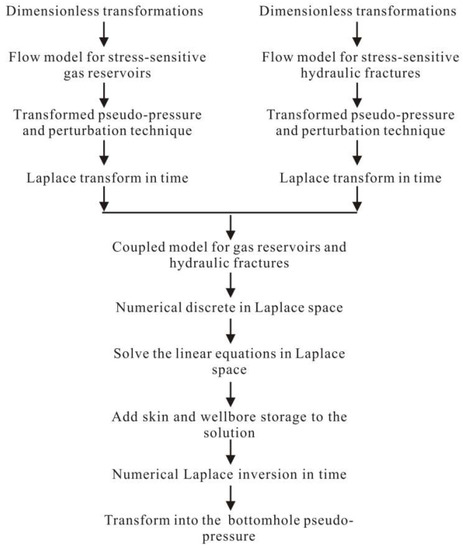
Figure 2.
Flow chart of the solution methodology.
3.1. Flow Model for Stress-Sensitive Gas Reservoirs
The reservoir permeability changes with reservoir pressure and can be described as follows [37]:
where is the pseudo-pressure, which is defined as
The governing equation of gas flow in stress-sensitive porous media is given as follows [37]:
Both gas viscosity and total compressibility in Equation (3) are functions of pressure. In order to simplify the proposed model and obtain an analytical solution, many research papers [26,37,38] treat the values of and in Equation (3) as constants, which could make the simulation results be accurate enough for engineering requirements. Following the suggestion by Wang [37], the values of and are evaluated at the initial condition, i.e., and in this paper.
With the assumption of the uniform initial pressure, the initial condition is expressed as
The gas reservoir is assumed to be laterally infinite, and thus, the outer boundary condition is
The inner boundary condition for a point source can be written as

Table 1.
Definitions of dimensionless variables.
The point source model including Equations (7)–(10) shows strong non-linearity which can be alleviated by introducing the following expression [16]:
The perturbation technique, Laplace transform, and superposition principle [39] were employed to obtain the pressure distribution in the gas reservoir with a vertical fractured well with multiple hydraulic fractures producing at a constant rate (see Appendix B):
3.2. Flow Model for Stress-Sensitive Hydraulic Fractures
The dimensionless model for gas flow within stress-sensitive hydraulic fractures is given as (see Appendix C)
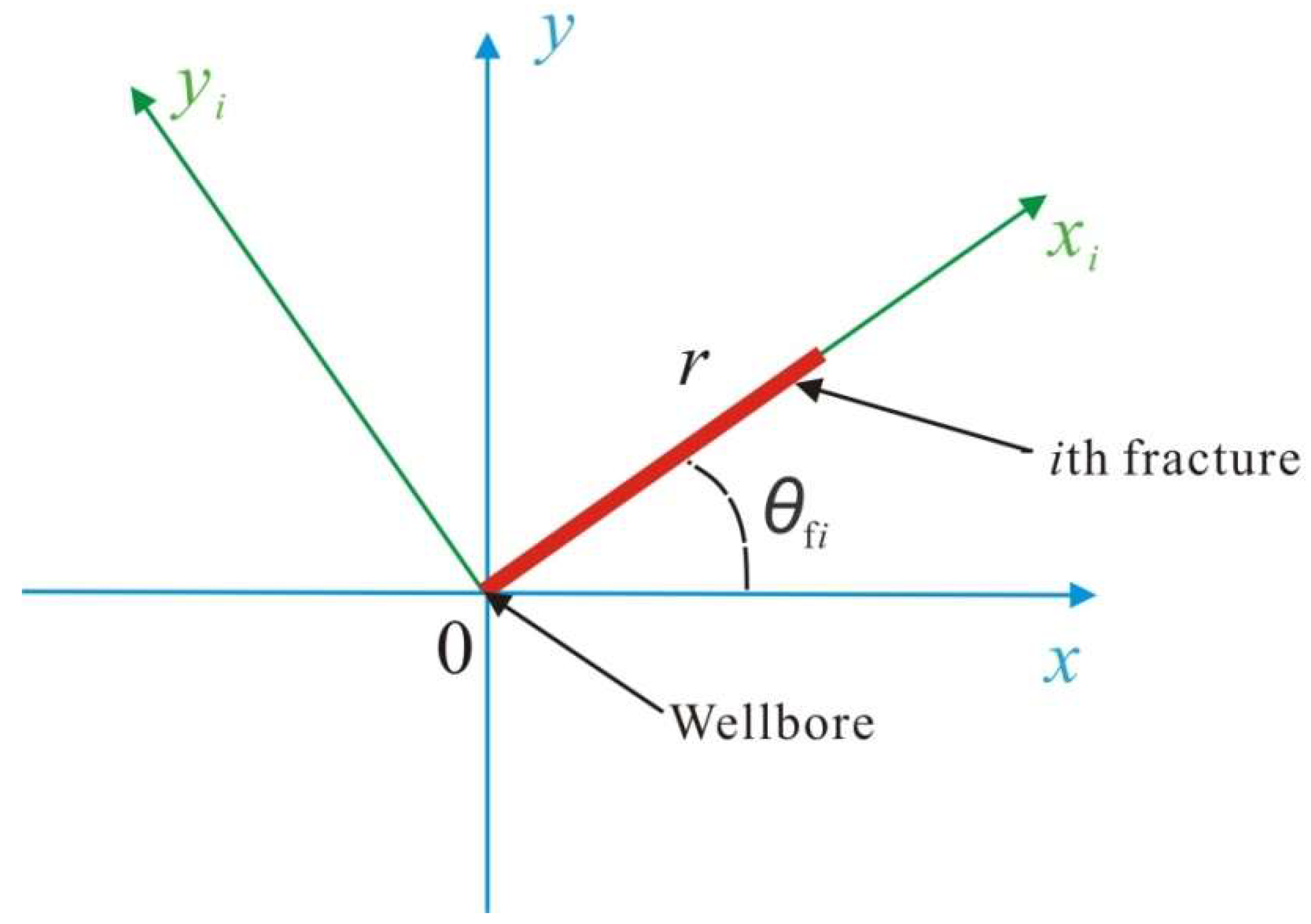
According to the relationship between Cartesian coordinate system and polar coordinate system (see Figure 3), Equations (13)–(16) can be rewritten in the polar coordinate system as follows:
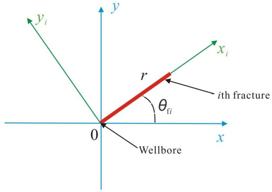
Figure 3.
Schematic of different coordinate systems.
Integrating Equation (17) from to with respect to yields
Substituting Equations (18) and (19) into Equation (21) yields
Integrating Equation (22) from to with respect to yields
where
3.3. Coupled Discrete Model
The flow model for gas reservoirs can associate with the flow model for hydraulic fractures by the following relationship:
Substituting Equations (11) and (A37) into Equation (25), one can derive
The zero-order perturbation solution of the is accurate enough in practice, and thus we can obtain
Combining Equations (26) and (27) yields that
Substituting Equation (28) into Equation (23) leads to
Taking the Laplace transform of Equation (29), one can obtain
Substituting Equation (12) into Equation (30), one can derive
Employing the Laplace transform of Equations (19) and (20), one can obtain
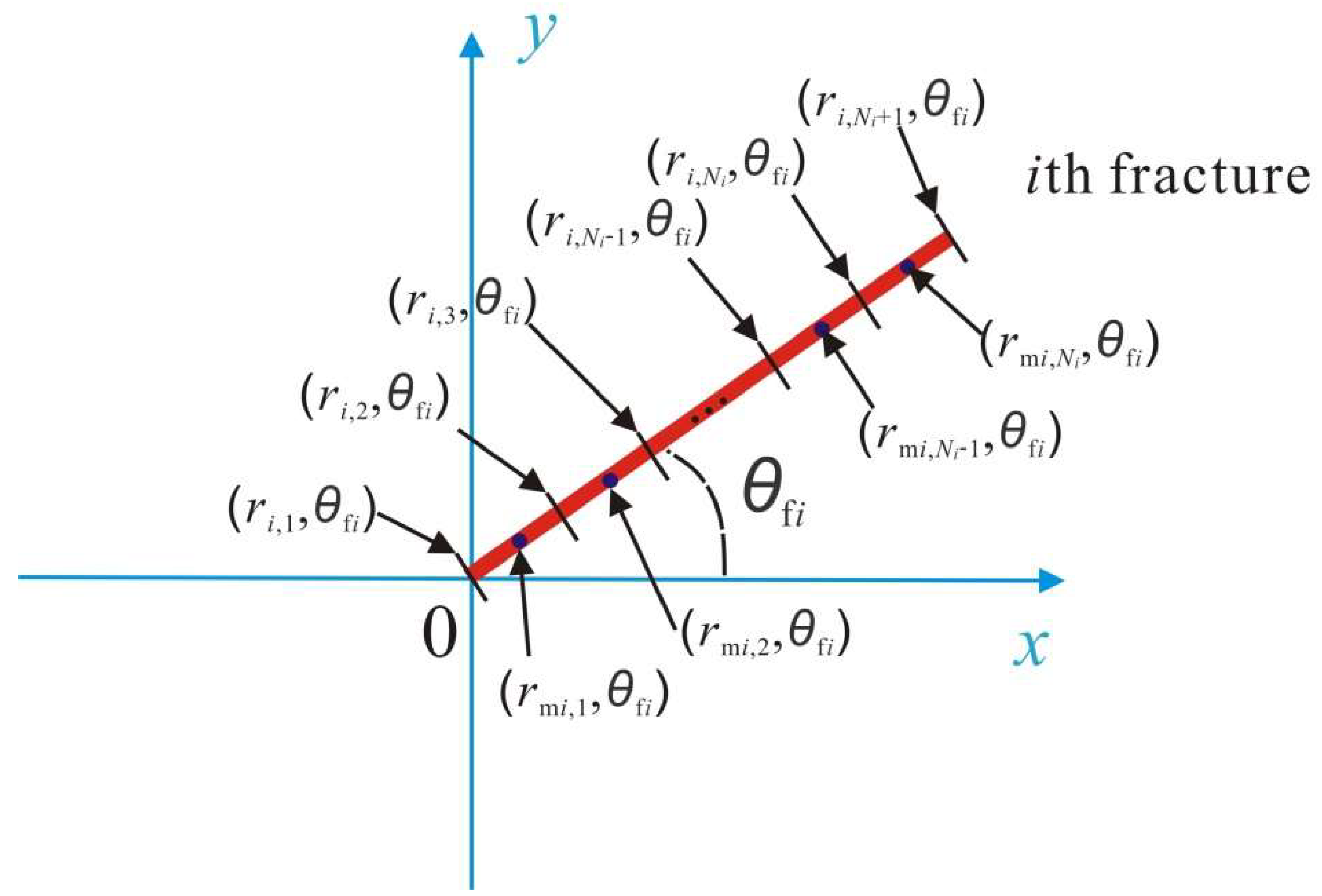
The coupled model consists of Equations (31) and (32), which can be solved by the numerical discrete method [40]. Each hydraulic fracture is discretized into some segments, and the flow rate in each segment is considered to stay the same at a certain time. The discrete schematic of a hydraulic fracture of a vertical fractured well is shown in Figure 4.
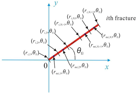
Figure 4.
Discrete schematic of the th hydraulic fracture of a vertical fractured well.
And then, the discrete forms of Equations (31) and (32) can be obtained as follows
where , and .
Equations (33) and (34) compose linear equations with unknowns. The unknowns are and , which can be obtained by solving the linear equations, and then the wellbore storage and the skin near the wellbore can be taken into account by the following formula [41]
With the aid of the numerical inversion method [42], in Laplace space is transformed into in real space
where
Finally, the dimensionless bottom-hole pseudo-pressure of a vertical fractured well with constant production rate is obtained by .
4. Model Validation and Application
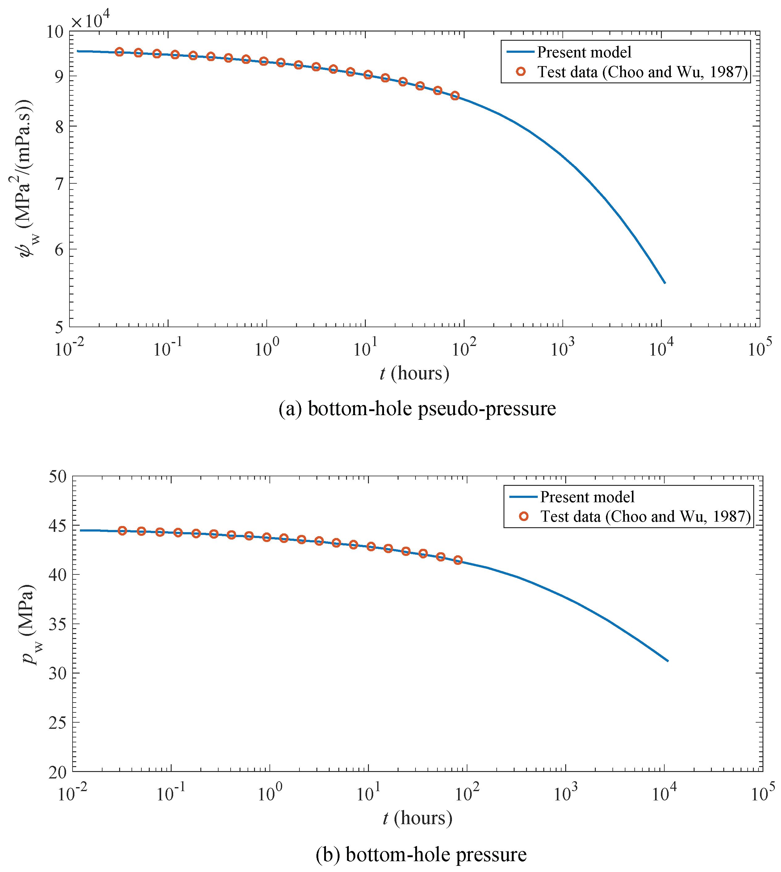
Because there is no analytical inversion solution of , it is difficult to discuss the accuracy of the Laplace transform by comparing the analytical inversion solution with the numerical inversion solution [43]. In order to validate the proposed model and show how this model was used in practice, the drawdown test data of a vertical fractured well with four fracture wings were collected from the published literature [44]. The drawdown test data in the literature [44] were generated by the reservoir simulator which is based on the implicit finite difference method. The vertical fractured well produces at a constant production rate of . Basic parameters of the vertical fractured well are listed in Table 2. The proposed model is employed to simulate the bottom-hole pressure under the constant-rate-production condition. The simulated bottom-hole pseudo-pressure and bottom-hole pressure are compared with the results published in the literature [44]. It is shown from Figure 5 that the simulated bottom-hole pseudo-pressure and bottom-hole pressure by the proposed model are in good agreement with the bottom-hole pressure data published in the literature [44], which validates the proposed model.
Table 2.
Parameters of a vertical fractured well with four fracture wings in the published literature [44].
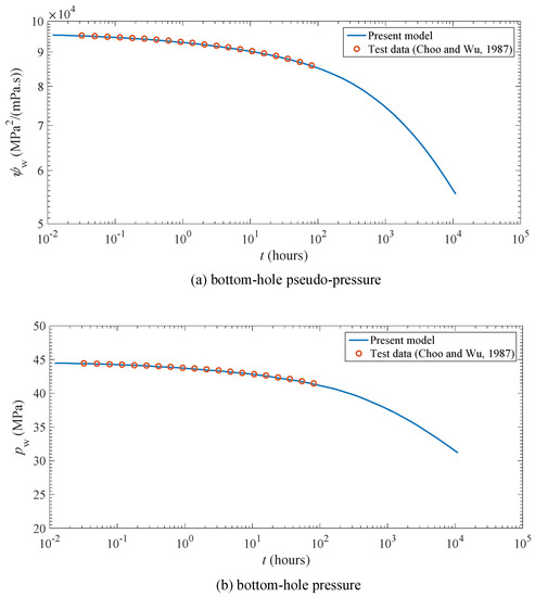
Figure 5.
Comparisons of bottom-hole pseudo-pressure and bottom-hole pressure between our simulation results and the test data [44]. (a) bottom-hole pseudo -pressure, (b) bottom-hole pressure
Furthermore, the proposed model can be used to predict the bottom-hole pressure under the constant-rate-production condition. Based on the proposed model, it was easy to obtain the bottom-hole pressure of the vertical fractured well at any given time. For example, when the vertical fractured well produces at a constant production rate of , the bottom-hole pressures are , , at , respectively.
5. Results and Analysis
5.1. Type Curves and Flow Regimes
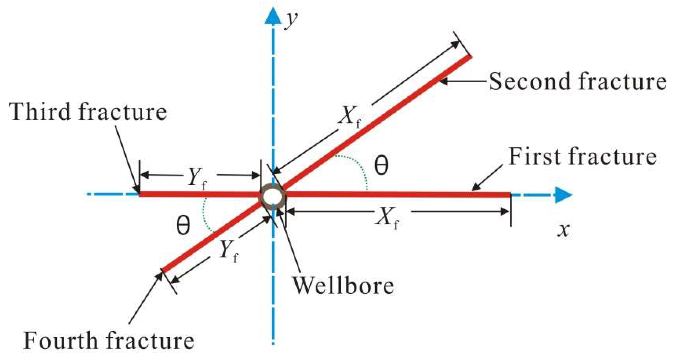
The bottom-hole pseudo-pressure of a vertical fractured well with multiple hydraulic fractures in stress-sensitive gas reservoirs was calculated by the proposed model. Type curves for the bottom-hole pseudo-pressure were plotted and the characteristics of the bottom-hole pseudo-pressure behavior was analyzed. The established model in this work was suitable for multiple hydraulic fractures with arbitrary fracture number, arbitrary fracture length, and arbitrary fracture orientation. In order to investigate the effect of the hydraulic-fracture distribution on the pseudo-pressure response, without loss of generality, we mainly focused on the vertical fractured well with four fracture wings which is shown in Figure 6. The first and second fracture wings were assumed to have the equal length , and the third and fourth fracture wings were set to be the equal length .
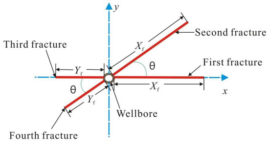
Figure 6.
Schematic of a vertical fractured well with four fracture wings.
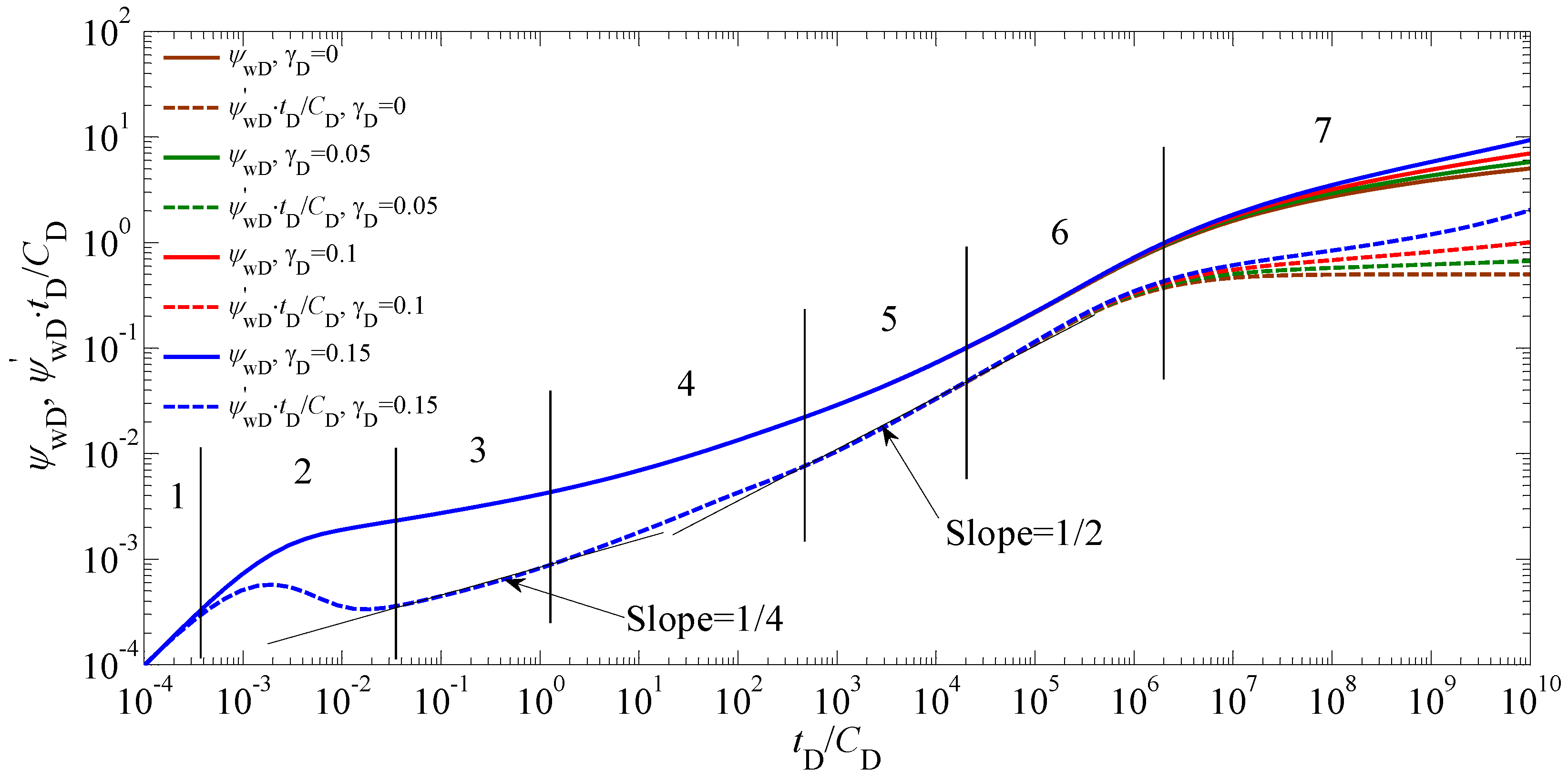
Figure 7 shows the type curves for the bottom-hole pseudo-pressure of a vertical fractured well with multiple hydraulic fractures in stress-sensitive gas reservoirs. The type curves for the bottom-hole pseudo-pressure consist of the pseudo-pressure curve (axis: , axis: ) and the pseudo-pressure derivative curve (axis: , axis: ). It is observed that there are seven possible flow regions in the type curves as follows:
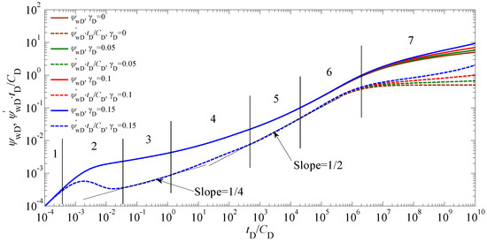
Figure 7.
Type curves for the bottom-hole pseudo-pressure of a vertical fractured well with multiple hydraulic fractures in stress-sensitive gas reservoirs with different values of the (, , , , , , ).
(1) Wellbore storage period (WSP): The produced gas comes from the storage gas in the wellbore, and the gas in the reservoir has not flowed into the wellbore. Both the pseudo-pressure curve and the pseudo-pressure derivative curve exhibit as straight lines with the slope being one.
(2) Transitional flow after wellbore storage period (TFAWSP): the gas in the reservoir begins to flow into the wellbore. This flow period is controlled by both the wellbore storage and skin near the wellbore. The pseudo-pressure derivative curve appears as a “hump”.
(3) Bilinear flow period (BFP): Linear flows take place within the hydraulic fractures and perpendicular to the hydraulic-facture surfaces in the reservoir simultaneously. The pseudo-pressure derivative curve exhibits as a straight line with the slope being 1/4.
(4) Transitional flow after bilinear flow period (TFABFP): The duration of this flow period is dependent on the difference of the hydraulic-fracture lengths. The shorter the hydraulic-fracture length is, the earlier the BFP ends. Therefore, this flow period will occur when the BFP of the shorter hydraulic fracture ends and the longer hydraulic fracture still lies in the BFP. The pseudo-pressure derivative curve appears as a straight line with the slope in the range of 1/4–1/2.
(5) Linear flow period (LFP): When the BFP of each hydraulic fracture ends, the LFP will appear. In this period, the linear flow perpendicular to the hydraulic-facture surfaces in the reservoir dominates in the area near the wellbore. The pseudo-pressure derivative curve appears as a straight line with the slope being 1/2.
(6) Transitional flow after linear flow period (TFALFP): When the pressure wave continues to travel in the reservoir, the interference between the pressure waves from different hydraulic fractures will take place, which makes the slope of the pseudo-pressure derivative curve be greater than 1/2. It should be noted that the stress sensitivity begins to obviously affect the type curves in this period. As the magnitude of the increases, the pseudo-pressure and its derivative curves are shifted up.
(7) Pseudo-radial flow period (PRFP): Compared with the previous flow period (i.e., the TFALFP), much slower growth of the pseudo-pressure drop was observed. The pseudo-pressure derivative without the effect of the stress sensitivity (i.e., ) keeps a value of 0.5, while the magnitude of the pseudo-pressure derivative with the effect of the stress sensitivity (i.e., ) increases with the time. Furthermore, the pseudo-pressure and its derivative increase with increasing the value of the at a fixed time. Therefore, if the stress sensitivity of the gas reservoir is stronger, the larger pressure drop is needed to remain the constant rate of produced well.
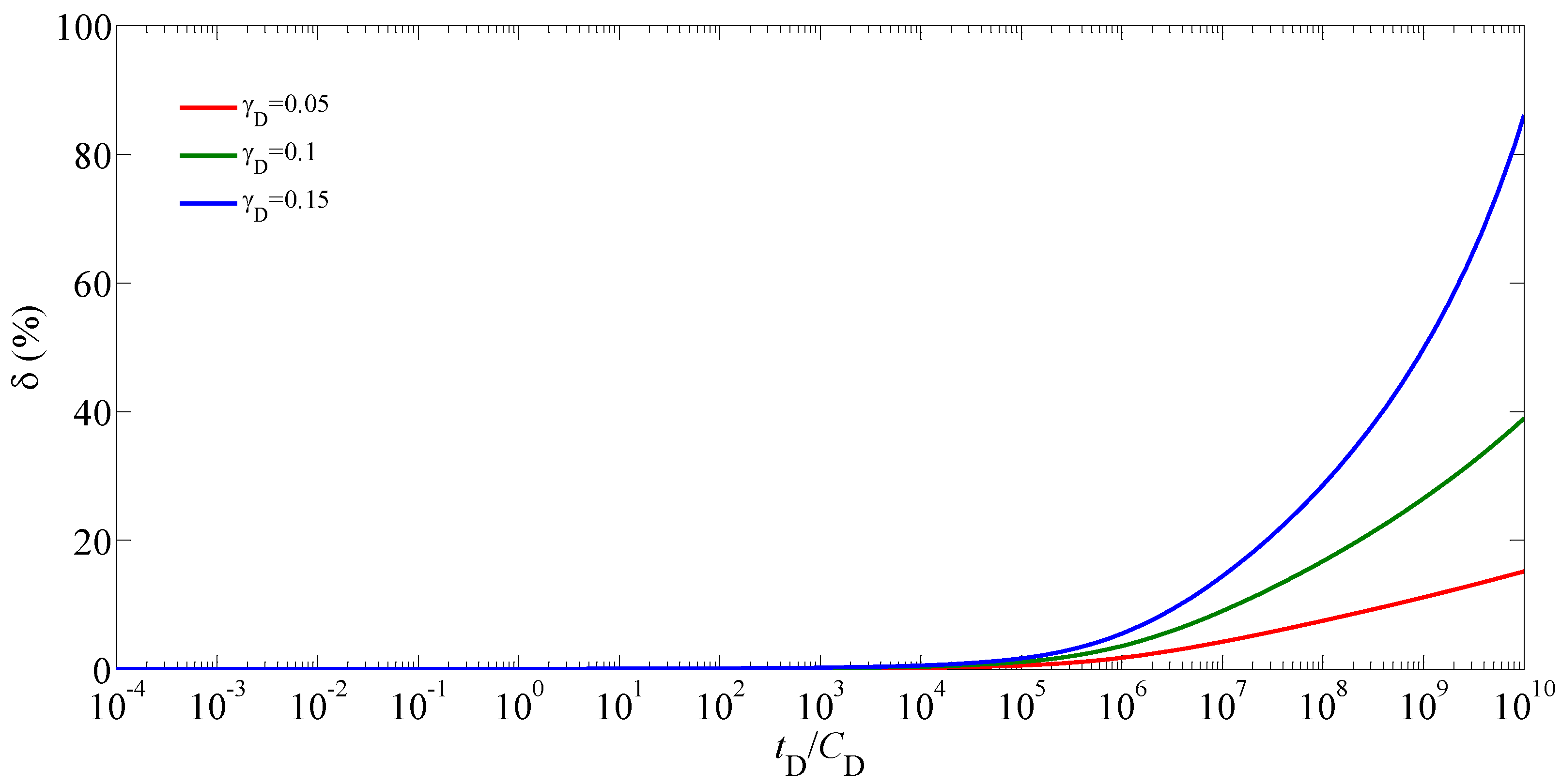
In order to quantify the effect of the stress sensitivity on the pseudo-pressure, the relative difference between the pseudo-pressures with and without the effect of the stress sensitivity is introduced as follows
where and are the bottom-hole pseudo-pressures with and without the effect of the stress sensitivity, respectively.
Figure 8 shows the effect of the dimensionless permeability modulus on the relative difference between the pseudo-pressures with and without the effect of the stress sensitivity. With the increase of the time, the relative difference first increases very slowly and finally increases rapidly. Considering the flow regimes, it was found that the impact of the stress sensitivity on the pseudo-pressure was negligibly small during and before the LFP, while after the LFP, this impact became more and more obvious with the increase of the time. Furthermore, the became larger with increasing the magnitude of the at a fixed time.

Figure 8.
Effect of the on the relative difference between the pseudo-pressures with and without the effect of the stress sensitivity (, , , , , , ).
5.2. Sensitivity Analysis
Besides the dimensionless permeability modulus , other parameters may have effects on the type curve and the relative difference between the pseudo-pressures with and without the effect of the stress sensitivity. Therefore, it is critical to conduct the sensitivity analysis of relevant parameters.
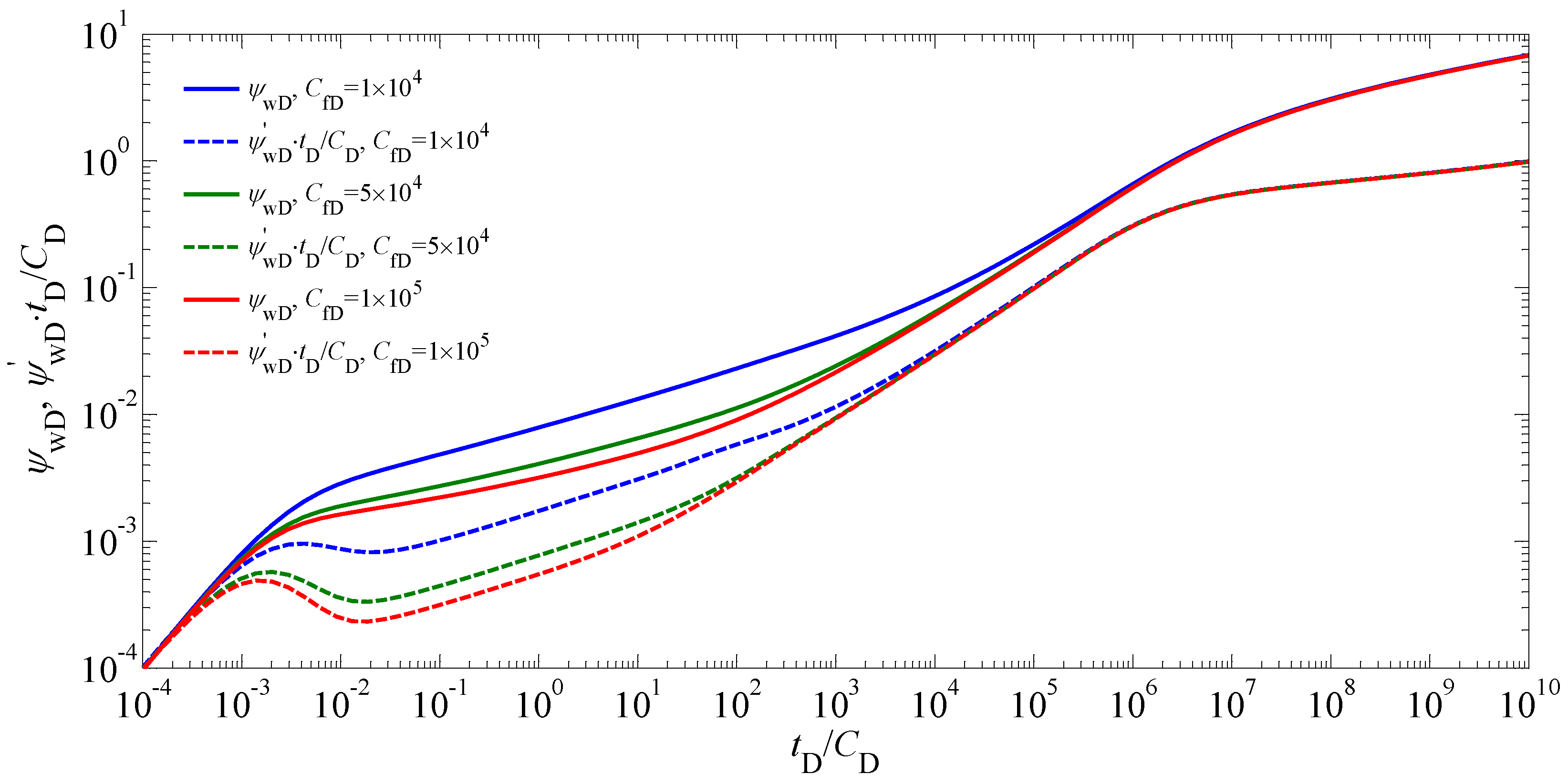
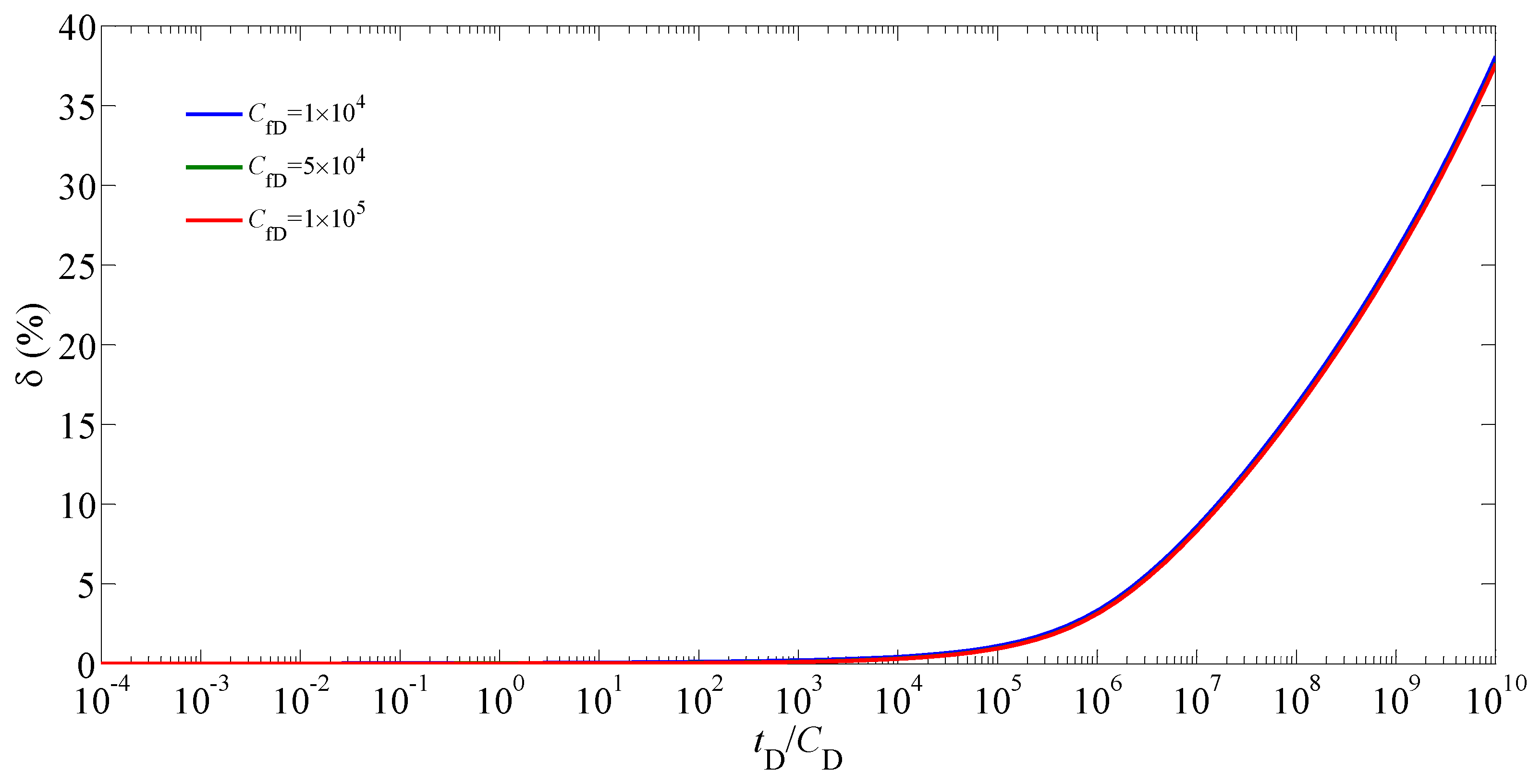
Figure 9 and Figure 10 show the effects of the fracture conductivity coefficient on the type curve and the relative difference between the pseudo-pressures with and without the effect of the stress sensitivity, respectively. It is obvious that the impact of the on the type curve takes place in the early periods (i.e., from the TFAWSP to the LFP), where the values of the pseudo-pressure and its derivative increase with the decrease of the magnitude of the . Furthermore, it was found from Figure 9 that as the value of the increases, the duration of the BFP becomes shorter and the start time of the LFP becomes earlier. As shown in Figure 10, the was little affected by the in all periods, and this was because the main impact of the on the pseudo-pressure occurred in the early periods, but the effect of the stress sensitivity on the pseudo-pressure was negligibly small in the early periods.
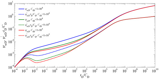
Figure 9.
Type curves for the bottom-hole pseudo-pressure of a vertical fractured well with multiple hydraulic fractures in stress-sensitive gas reservoirs with different values of the (, , , , , , ).
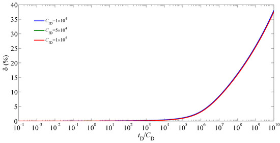
Figure 10.
Effect of the on the relative difference between the pseudo-pressures with and without the effect of the stress sensitivity (, , , , , , ).
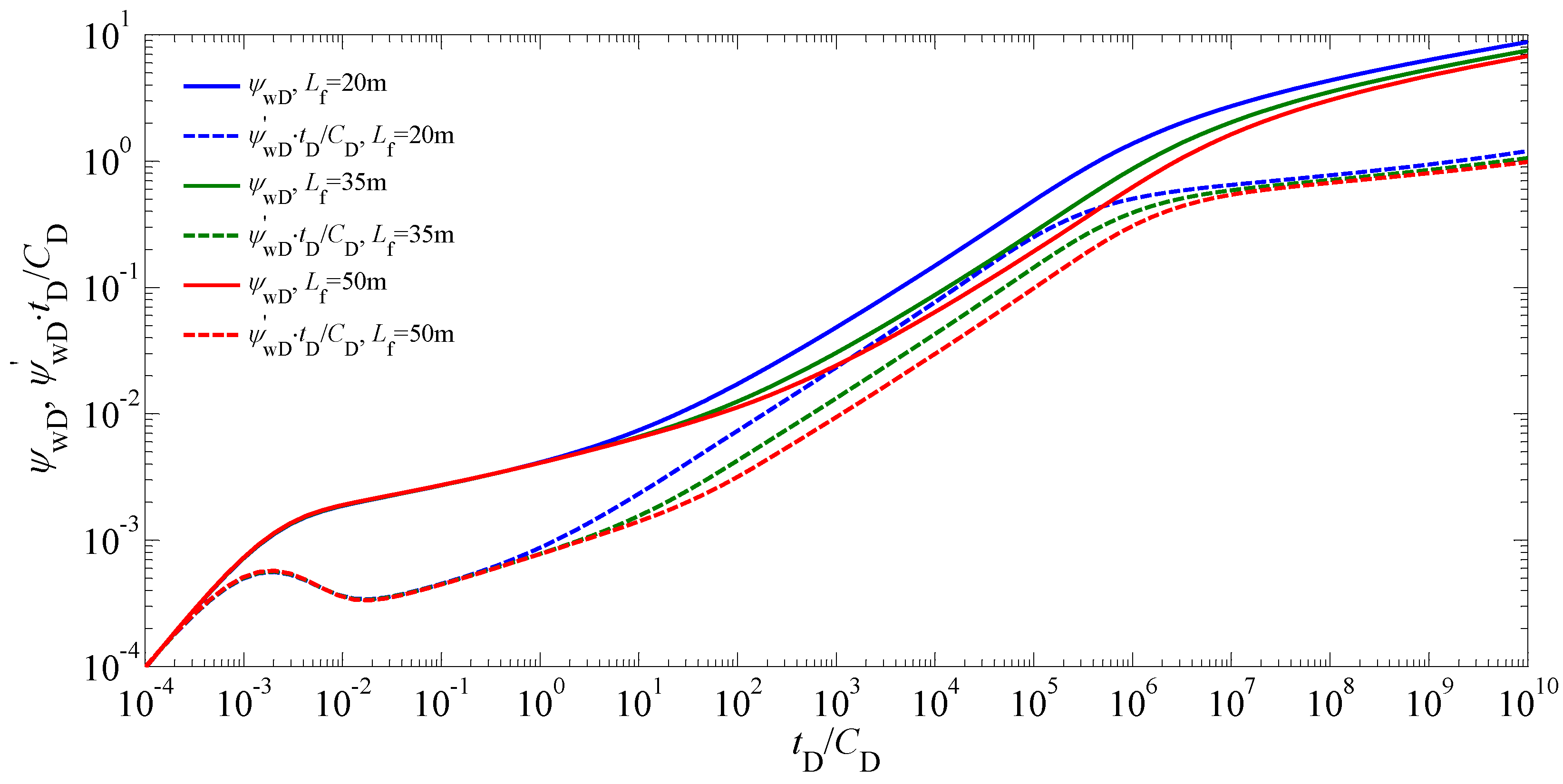
Figure 11 and Figure 12 show the effects of the length of the hydraulic fractures on the type curve and the relative difference between the pseudo-pressures with and without the effect of the stress sensitivity, respectively. It is seen from Figure 11 that the has an important effect on the magnitudes of the pseudo-pressure and its derivative in the intermediate and late flow periods (i.e., from the BFP to the PRFP). Decreasing the reduced the duration of the BFP and resulted in the increase of the pseudo-pressure and its derivative during and after the BFP. Furthermore, it was found from Figure 12 that the increased with decreasing the magnitude of the in the late flow period, indicating that the pseudo-pressure obtained by the conventional model without the effect of the stress sensitivity will result in a much bigger error when the length of the hydraulic fractures becomes shorter.
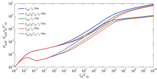
Figure 11.
Type curves for the bottom-hole pseudo-pressure of a vertical fractured well with multiple hydraulic fractures in stress-sensitive gas reservoirs with different values of the (, , , , , , ).
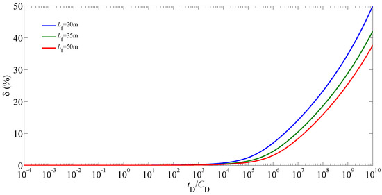
Figure 12.
Effect of the on the relative difference between the pseudo-pressures with and without the effect of the stress sensitivity (, , , , , , ).
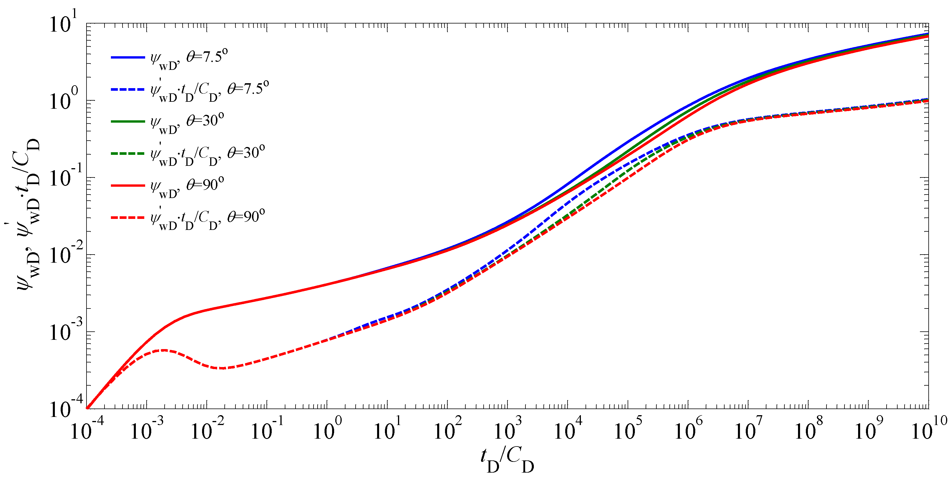
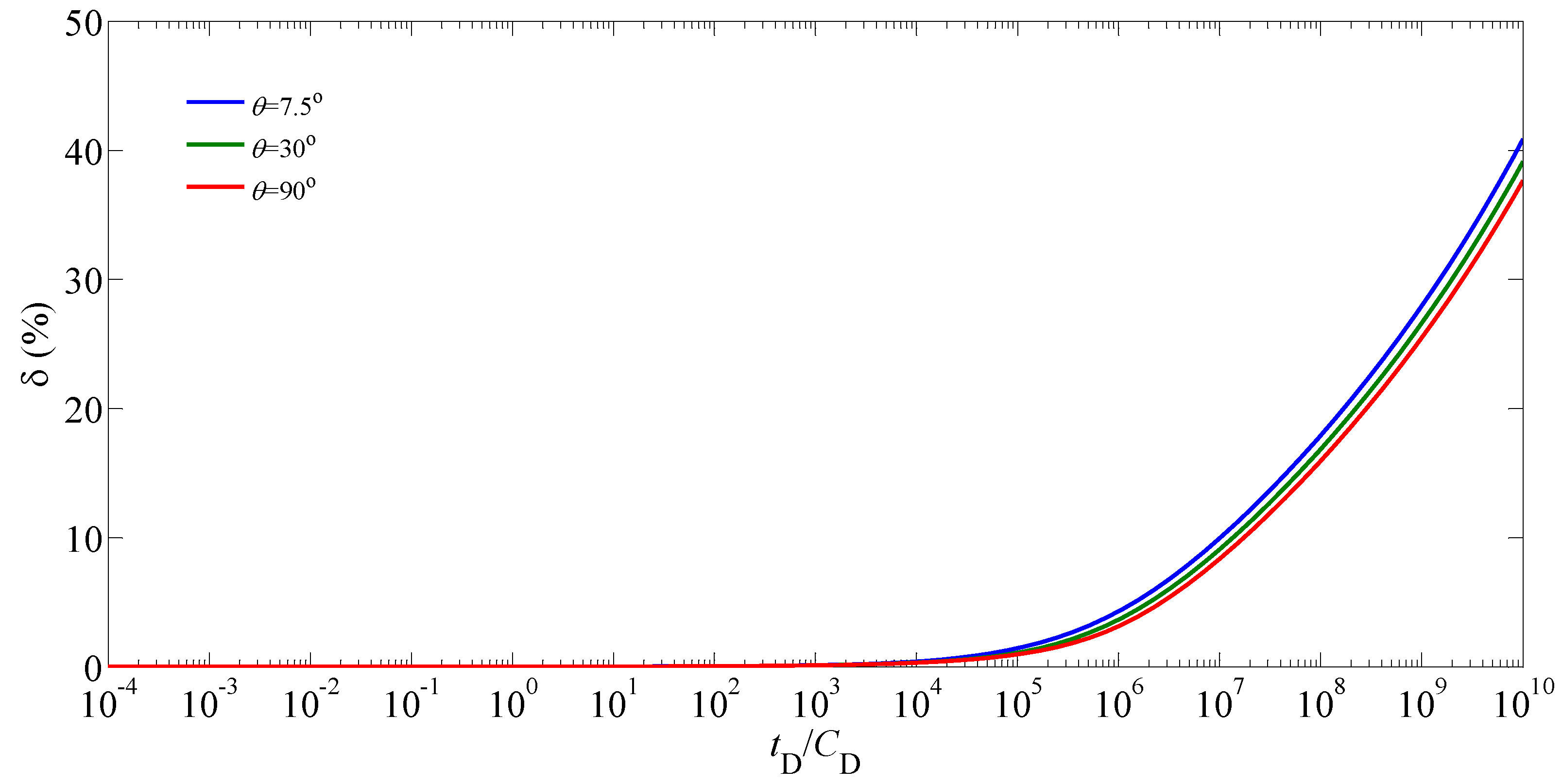
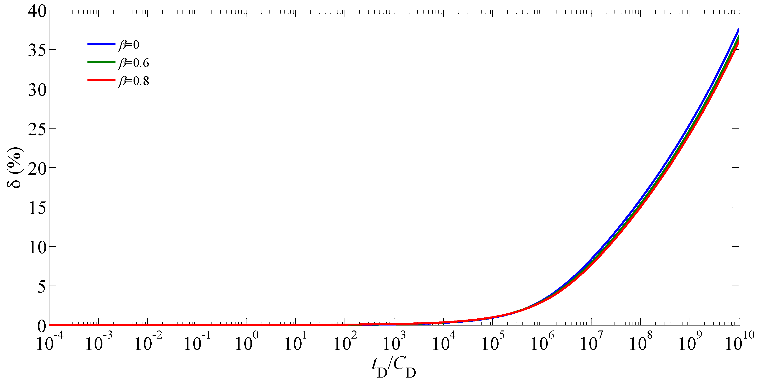
Figure 13 and Figure 14 show the effects of the angle between the two adjacent hydraulic fractures on the type curve and the relative difference between the pseudo-pressures with and without the effect of the stress sensitivity, respectively. As shown in Figure 13, with the decrease of the , the start time of the TFALFP becomes earlier, and the magnitudes of the pseudo-pressure and its derivative in the TFALFP increase. This is because decreasing the results in the earlier and stronger interference between the hydraulic fractures, which makes the pressure drop increase to remain the constant rate of the produced well. Whereas the impact of the on the type curve is relatively unobvious in the PRFP. Furthermore, it is seen from Figure 14 that the increases with decreasing the magnitude of the during and after the TFALFP, indicating that the effect of the stress sensitivity on the pseudo-pressure becomes greater when the decreases.

Figure 13.
Type curves for the bottom-hole pseudo-pressure of a vertical fractured well with multiple hydraulic fractures in stress-sensitive gas reservoirs with different values of the (, , , , , , ).
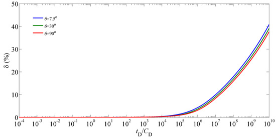
Figure 14.
Effect of the on the relative difference between the pseudo-pressures with and without the effect of the stress sensitivity (, , , , , , ).
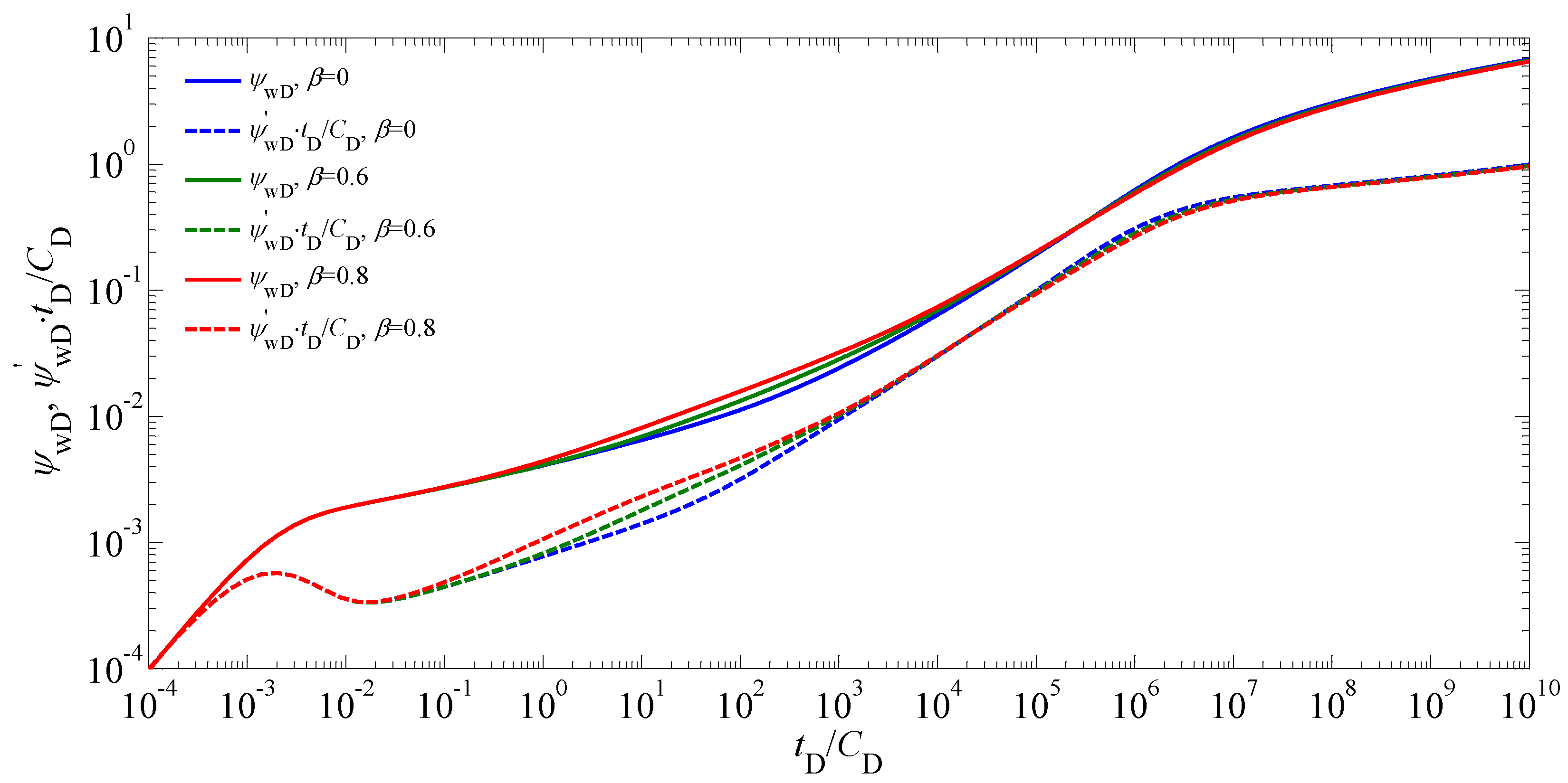
Introducing the coefficient of to quantify the difference of the hydraulic-fracture lengths, the effects of on the type curve, and the relative differences between the pseudo-pressures with and without the effect of the stress sensitivity are shown in Figure 15 and Figure 16, respectively. It is obvious that the difference of the hydraulic-fracture lengths becomes larger as the magnitude of the increases. The range of the is from zero to one. As shown in Figure 15, with the decrease of the , the end of the BFP takes place later, the duration of the TFABFP becomes shorter, and the start time of the LFP occurs earlier. The reason for the existence of the TFABFP is that the difference of the hydraulic-fracture lengths leads to the inconsistency of the end times for the BFP for each hydraulic fracture. If is equal to zero, the TFABFP may not even appear. Furthermore, the difference of the hydraulic-fracture lengths makes the pseudo-pressure and its derivative increase in the TFABFP. It is interesting to find in Figure 15 that during the TFALFP, the pseudo-pressure and its derivative increase as the decreases. This may be because that for the distribution of the hydraulic fractures shown in Figure 6, the interference between hydraulic fractures enhances with the decrease of the in the TFALFP. As shown in Figure 16, the has an effect on the error caused by neglecting the stress sensitivity during and after the TFALFP. Decreasing the results in the increase of the error.
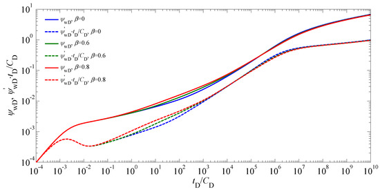
Figure 15.
Type curves for the bottom-hole pseudo-pressure of a vertical fractured well with multiple hydraulic fractures in stress-sensitive gas reservoirs with different values of the (, , , , , , , , ).
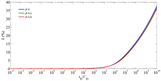
Figure 16.
Effect of the on the relative difference between the pseudo-pressures with and without the effect of the stress sensitivity (, , , , , , , , ).
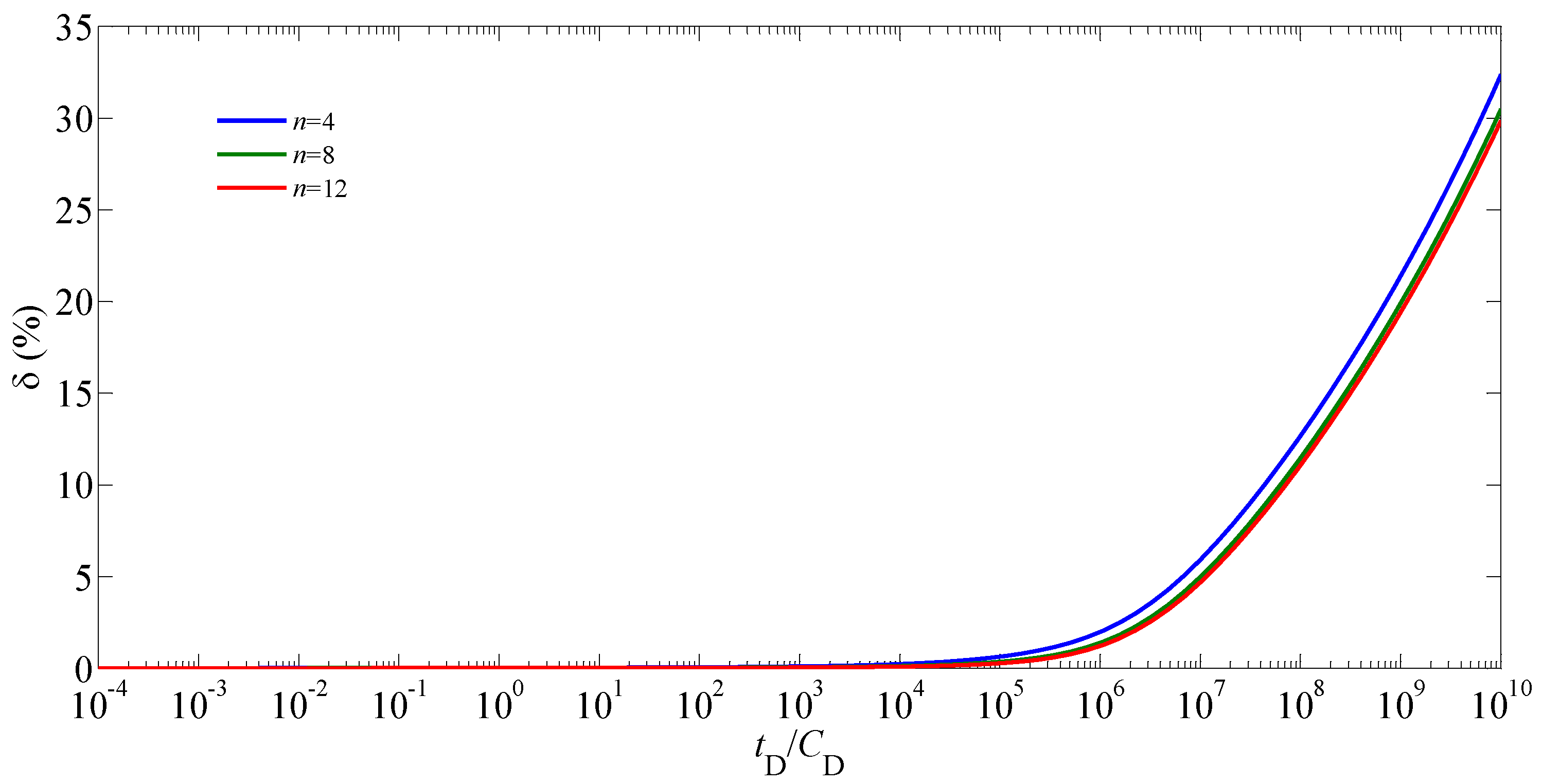
Figure 17 and Figure 18 show the effects of the hydraulic-fracture number on the type curve and the relative difference between the pseudo-pressures with and without the effect of the stress sensitivity, respectively. The distribution of the hydraulic fractures was assumed to be uniform (i.e., the angle between the two arbitrary adjacent hydraulic fractures was equal). As shown in Figure 17, it is obvious that the affects the pseudo-pressure behavior in all periods except for the WSP. Increasing the leads to the decrease of the pseudo-pressure and its derivative. Due to the increase of the , the angle between the two adjacent hydraulic fractures was reduced, and thus the interference between hydraulic fractures occurred earlier and the effect of this interference on the pseudo-pressure was more significant. Figure 18 indicates that a smaller value of the leads to a bigger error caused by neglecting the stress sensitivity during and after the TFALFP.
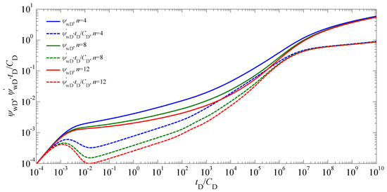
Figure 17.
Type curves for the bottom-hole pseudo-pressure of a vertical fractured well with multiple hydraulic fractures in stress-sensitive gas reservoirs with different values of the (, , , , , , ).
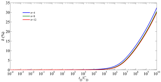
Figure 18.
Effect of on the relative difference between the pseudo-pressures with and without the effect of the stress sensitivity (, , , , , , ).
6. Conclusions
We have established a non-linear model of a vertical fractured well with multiple hydraulic fractures in gas reservoirs by incorporating the pressure-dependent permeability. Both transformed pseudo-pressure and perturbation techniques were employed to linearize the proposed model. Superposition principle and numerical discrete methods were used to obtain the semi-analytical solution. Type curves for pseudo-pressure were plotted and discussed in detail. The influence of relevant parameters on the type curve and the relative difference between the pseudo-pressures with and without the effect of the stress sensitivity were analyzed. Some main conclusions are listed as follows:
(1) The type curve of a vertical fractured well with multiple hydraulic fractures was identified by seven possible flow regions. Compared with the conventional model of a vertical fractured well with two symmetrical hydraulic-fracture wings, two transitional flow regimes (i.e., the TFABFP and TFALFP) were observed, which were caused by the difference of the hydraulic-fracture lengths and the interference between hydraulic fractures, respectively.
(2) As the time increased, the pressure drops increased, which made the permeability decrease. The impact of the stress sensitivity on the pseudo-pressure increased with the increase of the time. Furthermore, the influence of the stress sensitivity on the pseudo-pressure was negligibly small in the early and intermediate flow periods but becomes very significant in the late flow period.
(3) Some relevant parameters, such as dimensionless permeability modulus, fracture conductivity coefficient, hydraulic-fracture length, angle between the two adjacent hydraulic fractures, the difference of the hydraulic-fracture lengths, and hydraulic-fracture number, not only affected the type curve, but also have an influence of the error caused by neglecting the stress sensitivity.
Author Contributions
Data curation, Z.S.; Formal analysis, P.G.; Funding acquisition, J.R.; Investigation, Z.S.; Methodology, P.G.; Project administration, P.G.; Visualization, H.C.; Writing—original draft, Z.S.; Writing—review and editing, C.P.
Funding
We acknowledge the support provided by the Open Fund of the State Key Laboratory of Oil and Gas Reservoir Geology and Exploitation (PLN201627) and the Scientific Research Starting Project of SWPU (No. 2017QHZ031).
Conflicts of Interest
The authors declare no conflict of interest.
Appendix A. Symbol Description
| Nomenclature | |
| wellbore storage coefficient, | |
| fracture conductivity coefficient | |
| total compressibility of hydraulic fracture, | |
| total compressibility of gas reservoir, | |
| reservoir thickness, | |
| reservoir permeability, | |
| initial fracture permeability, | |
| initial reservoir permeability, | |
| length of the th hydraulic fracture, | |
| hydraulic-fracture number | |
| reservoir pressure, | |
| fracture pressure, | |
| initial reservoir pressure, | |
| pressure at standard condition, | |
| flow rate of point source, | |
| flow-rate density, | |
| production rate of the th hydraulic fracture, | |
| well production rate, | |
| radial distance, , | |
| wellbore radius, | |
| Laplace transform variable | |
| skin factor | |
| time, | |
| reservoir temperature, | |
| temperature at standard condition, | |
| fracture width, | |
| - and -coordinates, | |
| Z-factor of gas | |
| gas viscosity, | |
| permeability modulus, | |
| reservoir pseudo-pressure, | |
| fracture pseudo-pressure, | |
| initial reservoir pseudo-pressure, | |
| bottom-hole pseudo-pressure, | |
| dimensionless transformed reservoir pseudo-pressure | |
| dimensionless transformed fracture pseudo-pressure | |
| dimensionless transformed bottom-hole pseudo-pressure with wellbore storage and skin | |
| dimensionless transformed bottom-hole pseudo-pressure without wellbore storage and skin | |
| reservoir porosity | |
| fracture porosity | |
| polar angle, degree | |
| polar angle of the th hydraulic fracture, degree | |
| length of discrete segment of the th hydraulic fracture, | |
| Subscript | |
| dimensionless | |
| the jth discrete segment in the ith hydraulic fracture | |
| Superscript | |
| Laplace space | |
Appendix B. Pressure Distribution in a Gas Reservoir with a Vertical Fractured Well with Multiple Hydraulic Fractures Producing at a Constant Rate
With the aid of Equation (11), Equations (7)–(10) can be rewritten as
The perturbation technique of was employed to obtain that
Considering a small value of in general, the zero-order perturbation solution was accurate enough for engineering requirements. So, Equations (A1)–(A4) can be rewritten as
Laplace transform was employed to solve the above model and it is defined by
where is an arbitrary variable in real space.
Taking the Laplace transform of Equations (A8)–(A11), one can obtain
The solution of Equations (A13)–(A15) in Laplace space can be derived as
According to Equation (A16), the superposition principle [39] was employed to obtain the pressure distribution in a gas reservoir with a vertical fractured well with multiple hydraulic fractures producing at a constant rate
Appendix C. Derivation of Dimensionless Model for Gas Flow within Stress-Sensitive Hydraulic Fractures
Considering the effect of the pressure-dependent permeability of hydraulic fractures, the governing equation for gas flow in the th hydraulic fracture is
where , .
The volume within the hydraulic fracture was very small, and thus the compressibility of the hydraulic fracture was neglected. Then Equation (A18) was reduced to
The flow-rate density of the th hydraulic fracture is given as
where .
The interface boundary condition between the wellbore and the th hydraulic fracture is
where is the production rate from the th hydraulic fracture, which is expressed as
The total production rate of the vertical fractured well is the sum of the production rate of each hydraulic fracture, and thus we can obtain
The gas velocity should be continuous at the interface between the hydraulic fracture and reservoir, and thus the boundary conditions of the fracture surface are given as
Introducing the following expressions [16]
Equations (A19)–(A21), (A24), and (A25) can be rewritten as
The width of the hydraulic fracture was very small, and thus the pressure changes within the th hydraulic fracture in the direction can be neglected. Then the average pressure within the th hydraulic fracture in the direction is introduced as follows:
With the aid of Equations (A31)–(A33), Equation (A28) becomes
Substituting Equation (A29) into Equation (A34) yields
According to Equation (A33), Equation (A30) is expressed as
Introducing the dimensionless variables, Equations (A26), (A35), (A36) are rewritten as follows:
The dimensionless expressions of Equations (A22) and (A23) are given as
References
- Wang, Y.; Zhang, C.; Chen, T.; Ma, X. Modeling the Nonlinear Flow for a Multiple-fractured Horizontal Well with Multiple Finite-conductivity Fractures in Triple Media Carbonate Reservoir. J. Porous Media 2018, 21, 1283–1305. [Google Scholar] [CrossRef]
- Wang, Y.; Yi, X. Flow Modeling of Well Test Analysis for A Multiple-fractured Horizontal Well in Triple Media Carbonate Reservoir. Int. J. Nonlinear Sci. Numer. Simul. 2018, 19, 439–457. [Google Scholar] [CrossRef]
- Wang, Y.; Yi, X. Transient Pressure Behavior of a Fractured Vertical Well with A Finite-conductivity Fracture in Triple Media Carbonate Reservoir. J. Porous Media 2017, 20, 707–722. [Google Scholar] [CrossRef]
- Ren, J.; Guo, P. A Novel Semi-analytical Model for Finite-conductivity Multiple Fractured Horizontal Wells in Shale Gas Reservoirs. J. Nat. Gas Sci. Eng. 2015, 24, 35–51. [Google Scholar] [CrossRef]
- Ren, J.; Guo, P. Anomalous Diffusion Performance of Multiple Fractured Horizontal Wells in Shale Gas Reservoirs. J. Nat. Gas Sci. Eng. 2015, 26, 642–651. [Google Scholar] [CrossRef]
- Ren, J.; Guo, P. Nonlinear Seepage Model for Multiple Fractured Horizontal Wells with the Effect of the Quadratic Gradient Term. J. Porous Media 2018, 21, 223–239. [Google Scholar] [CrossRef]
- Ren, J.; Guo, P. A General Analytical Method for Transient Flow Rate with the Stress-sensitive Effect. J. Hydrol. 2018, 565, 262–275. [Google Scholar] [CrossRef]
- Ren, J.; Guo, P. Analytical Method for Transient Flow Rate with the Effect of the Quadratic Gradient Term. J. Pet. Sci. Eng. 2018, 162, 774–784. [Google Scholar] [CrossRef]
- Ren, J.; Guo, P.; Peng, S.; Ma, Z. Performance of Multi-stage Fractured Horizontal Wells with Stimulated Reservoir Volume in Tight Gas Reservoirs Considering Anomalous Diffusion. Environ. Earth Sci. 2018, 77, 768. [Google Scholar] [CrossRef]
- Ren, J.; Guo, P.; Guo, Z.; Wang, Z. A Lattice Boltzmann Model for simulating Gas Flow in Kerogen Pores. Transp. Porous Med. 2015, 106, 285–301. [Google Scholar] [CrossRef]
- Ren, J.; Guo, P.; Peng, S.; Yang, C. Investigation on Permeability of Shale Matrix using the Lattice Boltzmann Method. J. Nat. Gas Sci. Eng. 2016, 29, 169–175. [Google Scholar] [CrossRef]
- Ren, J.; Guo, P.; Guo, Z. Rectangular Lattice Boltzmann Equation for Gaseous Microscale Flow. Adv. Appl. Math. Mech. 2016, 8, 306–330. [Google Scholar] [CrossRef]
- Ren, J.; Guo, P. Lattice Boltzmann Simulation of Steady Flow in a Semi-Elliptical Cavity. Commun. Comput. Phys. 2017, 21, 692–717. [Google Scholar] [CrossRef]
- Ren, J.; Zheng, Q.; Guo, P.; Peng, S.; Wang, Z.; Du, J. Pore-scale Lattice Boltzmann Simulation of Two-component Shale Gas Flow. J. Nat. Gas Sci. Eng. 2019, 61, 46–70. [Google Scholar] [CrossRef]
- Ren, J.; Zheng, Q.; Guo, P.; Zhao, C. Lattice Boltzmann Model for Gas Flow through Tight Porous Media with Multiple Mechanisms. Entropy 2019, 21, 133. [Google Scholar] [CrossRef]
- Pedrosa, O.A. Pressure Transient Response in Stress-Sensitive Formations; SPE California Regional Meeting: Oakland, CA, USA, 1986. [Google Scholar]
- Zhang, Z.; He, S.; Liu, G.; Guo, X.; Mo, S. Pressure Buildup Behavior of Vertically Fractured Wells with Stress-sensitive Conductivity. J. Pet. Sci. Eng. 2014, 122, 48–55. [Google Scholar] [CrossRef]
- Wang, J.; Jia, A.; Wei, Y.; Qi, Y. Approximate Semi-analytical Modeling of Transient Behavior of Horizontal Well Intercepted by Multiple Pressure-dependent Conductivity Fractures in Pressure-sensitive Reservoir. J. Pet. Sci. Eng. 2017, 153, 157–177. [Google Scholar] [CrossRef]
- Gringarten, A.C.; Ramey, H.J.; Raghavan, J.R. Unsteady-state Pressure Distributions Created by a Well with a Single Infinite-conductivity Vertical Fracture. SPE J. 1974, 14, 347–360. [Google Scholar] [CrossRef]
- Cinco-Ley, H.; Samaniego, F.; Dominguez, N. Transient Pressure Behavior for a Well with a Finite-conductivity Vertical Fracture. SPE J. 1978, 18, 253–264. [Google Scholar]
- Bennett, C.O.; Reynolds, A.C.; Raghavan, R.; Elbel, J.L. Performance of Finite-conductivity, Vertically Fractured Wells in Single-layer Reservoirs. SPE Form. Eval. 1986, 1, 399–412. [Google Scholar] [CrossRef]
- Bennett, C.O.; Rosato, N.D.; Reynolds, A.C.; Raghavan, R. Influence of Fracture Heterogeneity and Wing Length on the Response of Vertically Fractured Wells. SPE J. 1983, 23, 219–230. [Google Scholar] [CrossRef]
- Rodriguez, F.; Cinco-Ley, H.; Samaniego, V.F. Evaluation of Fracture Asymmetry of Finite-conductivity Fractured Wells. SPE Prod. Eval. 1992, 7, 233–239. [Google Scholar] [CrossRef]
- Berumen, S.; Tiab, D.; Rodriguez, F. Constant Rate Solutions for a Fractured Well with an Asymmetric Fracture. J. Pet. Sci. Eng. 2000, 25, 49–58. [Google Scholar] [CrossRef]
- Tiab, D.; Lu, J.; Nguyen, H.; Owayed, J. Evaluation of Fracture Asymmetry of Finite-conductivity Fractured Wells. J. Energy Resour. Technol. 2010, 132, 1–7. [Google Scholar] [CrossRef]
- Wang, L.; Wang, X.; Li, J.; Wang, J. Simulation of Pressure Transient Behavior for Asymmetrically Finite-conductivity Fractured Wells in Coal Reservoirs. Transp. Porous Media 2013, 97, 353–372. [Google Scholar] [CrossRef]
- Wang, L.; Wang, X. Type Curves Analysis for Asymmetrically Fractured Wells. J. Energy Resour. Technol. 2014, 136, 023101. [Google Scholar] [CrossRef]
- Fisher, M.K.; Wright, C.A.; Davidson, B.M.; Goodwin, A.K.; Fielder, E.O.; Buckler, W.S.; Steinsberger, N.P. Integrating Fracture Mapping Technologies to Improve Stimulations in the Barnett Shale. SPE Prod. Facil. 2005, 20, 85–93. [Google Scholar] [CrossRef]
- Mayerhofer, M.J.; Lolon, E.P.; Youngblood, J.E.; Heinze, J.R. Integration of Microseismic-Fracture-Mapping Results with Numerical Fracture Network Production Modeling in the Barnett Shale; SPE Annual Technical Conference and Exhibition: San Antonio, TX, USA, 2006. [Google Scholar]
- Fan, Z.Q.; Jin, Z.H.; Johnson, S.E. Oil-gas Transformation Induced Subcritical Crack Propagation and Coalescence in Petroleum Source Rocks. Int. J. Fract. 2014, 185, 187–194. [Google Scholar] [CrossRef]
- Ren, J.; Guo, P. Nonlinear Flow Model of Multiple Fractured Horizontal Wells with Stimulated Reservoir Volume including the Quadratic Gradient Term. J. Hydrol. 2017, 554, 155–172. [Google Scholar] [CrossRef]
- Shaoul, J.R.; Behr, A.; Mtchedlishvili, G. Developing a Tool for 3D Reservoir Simulation of Hydraulically Fractured Wells. SPE Reservoir Eval. Eng. 2007, 10, 50–59. [Google Scholar] [CrossRef]
- Restrepo, D.P.; Tiab, D. Multiple fractures transient response. In Proceedings of the SPE Latin American and Caribbean Petroleum Engineering Conference, Cartagena de Indias, Colombia, 31 May–3 June 2009. [Google Scholar]
- Wang, L.; Wang, X.; Luo, E.; Wang, J. Analytical Modeling of Flow Behavior for Wormholes in Naturally Fractured-vuggy Porous Media. Transp. Porous Media 2014, 105, 539–558. [Google Scholar] [CrossRef]
- Ren, J.; Guo, P. Performance of Vertical Fractured Wells with Multiple Finite-conductivity Fractures. J. Geophys. Eng. 2015, 12, 978–987. [Google Scholar] [CrossRef]
- Luo, W.; Tang, C. Pressure-transient Analysis of Multiwing Fractures Connected to a Vertical Wellbore. SPE J. 2015, 20, 360–367. [Google Scholar] [CrossRef]
- Wang, H.T. Performance of Multiple Fractured Horizontal Wells in Shale Gas Reservoirs with Consideration of Multiple Mechanisms. J. Hydrol. 2014, 510, 299–312. [Google Scholar] [CrossRef]
- Li, X.P.; Cao, L.N.; Luo, C.; Zhang, B.; Zhang, J.Q.; Tan, X.H. Characteristics of Transient Production Rate Performance of Horizontal Well in Fractured Tight Gas Reservoirs with Stress-sensitivity Effect. J. Pet. Sci. Eng. 2017, 158, 92–106. [Google Scholar] [CrossRef]
- Ozkan, E. Performance of Horizontal Wells. Ph.D. Thesis, University of Tulsa, Tulsa, OK, USA, 1988. [Google Scholar]
- Wan, J. Well Models of Hydraulically Fractured Horizontal Wells. Master’s Thesis, Stanford University, Palo Alto, CA, USA, 1999. [Google Scholar]
- Van Everdingen, A.F.; Hurst, W. The Application of the Laplace Transformation to Flow Problems in Reservoirs. Trans. AIME 1949, 186, 305–324. [Google Scholar] [CrossRef]
- Stehfest, H. Numerical Inversion of Laplace Transforms. Commun. ACM 1970, 13, 47–49. [Google Scholar] [CrossRef]
- Akanji, L.T.; Falade, G.K. Closed-Form Solution of Radial Transport of Tracers in Porous Media Influenced by Linear Drift. Energies 2019, 12, 29. [Google Scholar] [CrossRef]
- Choo, Y.K.; Wu, C.H. Transient Pressure Behavior of Multiple-fractured Gas Wells. In Proceedings of the SPE/DOE Low Permeability Reservoirs Symposium, Denver, CO, USA, 18–19 May 1987. [Google Scholar]


© 2019 by the authors. Licensee MDPI, Basel, Switzerland. This article is an open access article distributed under the terms and conditions of the Creative Commons Attribution (CC BY) license (http://creativecommons.org/licenses/by/4.0/).