Article

Research on Control Methods for the Pressure Continuous Regulation Electrohydraulic Proportional Axial Piston Pump of an Aircraft Hydraulic System

School of Automation Science and Electric Engineering, Beihang University, Beijing 100191, China
*
Authors to whom correspondence should be addressed.
Appl. Sci. 2019, 9(7), 1376; https://doi.org/10.3390/app9071376
Submission received: 12 February 2019 / Revised: 18 March 2019 / Accepted: 18 March 2019 / Published: 1 April 2019

Abstract

:

Featured Application

A structural scheme is proposed to match the pump delivery pressure and the aircraft load. PID, LQR and backstepping sliding control method are used.

Abstract

The objective of this paper is to design a pump that can match its delivery pressure to the aircraft load. Axial piston pumps used in airborne hydraulic systems are required to work in a constant pressure mode setting based on the highest pressure required by the aircraft load. However, the time using the highest pressure working mode is very short, which leads to a lot of overflow lose. This study is motivated by this fact. Pressure continuous regulation electrohydraulic proportional axial piston pump is realized by combining a dual-pressure piston pump with electro-hydraulic proportional technology, realizing the match between the delivery pressure of the pump and the aircraft load. The mathematical model is established and its dynamic characteristics are analyzed. The control methods such as a proportional integral derivative (PID) control method, linear quadratic regulator (LQR) based on a feedback linearization method and a backstepping sliding control method are designed for this nonlinear system. It can be seen from the result of simulation experiments that the requirements of pressure control with a pump are reached and the capacity of resisting disturbance of the system is strong.

1. Introduction

The delivery pressure of the axial piston pump used in an airborne hydraulic system shown in Figure 1 must be set according to the highest pressure required by the aircraft load. Most of the hydraulic power is consumed in the form of overflow loss, causing low pressure to account for most of the flight time. The main form of overflow loss is the generation of a large amount of heat, which leads to an increase in temperature of the hydraulic system. This situation accelerates the progress of aging for the hydraulic oil and sealing rubber. The statistic data indicate that service life of mineral oil will be reduced by 90% when the fluid temperature is raised by 15 °C [1,2].
The variable pressure airborne hydraulic system is an effective method to solve this problem. At present, there are two aircraft hydraulic system pump source forms being proposed: dual pressure variable pump and intelligent variable pressure pump.
A dual pressure variable pump (Dual Pressure Pump) airborne system has been put forward by the United States, Britain and other countries. During flight, the dual pressure pump operates in a high-pressure mode when required, and a low-pressure mode is used during the rest of the time. Compared to the constant pressure variable pump, energy efficiency has been greatly improved [3].
The dual-pressure variable pump of 21–35 MPa (3000–5000 psi) has been used in the F/A-18E/F by the United States [4]. Related research on dual pressure pumps can be found in many references. The dynamic mathematical model of the pressure regulation mechanism has been established, and numerical simulation research has been carried out. Methods such as setting the orifice and the effective volume of the pump outlet are used to reduce pressure overshoot [5,6].
But the matching problem between the delivery pressure of the pump and the aircraft load is only partially solved. If the requirement of aircraft load is slightly above the low-pressure mode and far below the high-pressure mode, the pump needs to operate under a high-pressure mode and the power loss is still considerable.
An intelligent variable pressure pump is another method to solve the problem. In the 1980s, engineers started to conduct research on intelligent variable pressure pumps. Because the intelligent hydraulic power supply system can provide fluid according to flight profile requirements, the power loss can be decreased. Abex corporation did some experiments on the F-15 “Iron Bird” [7]. The result indicated that the intelligent pump decreases the consumed power by 39% and the discharge fluid temperature decreases between 18 °C and 24 °C [8,9]. Researchers have done a lot of research this. The intelligent pump is optimized by taking the system work efficiency as the objective function and the performance reliability index as the constraint condition. Compared to conventional constant pressure pump systems, the average efficiency of the intelligent pump system increased by 15% [10]. Some control methods such as sliding mode variable structure control, adaptive control strategy, proportional integral derivative (PID) control strategy, etc. are used for precise control of swash plate inclination and outlet pressure of intelligent pumps [11,12,13]. But the structure of the intelligent variable pressure pump system is complex, and sensors are needed to detect the signals of pressure, including temperature, swashplate inclination, etc.
By introducing electro-hydraulic proportional technology to the existing dual-pressure piston pump, the delivery pressure of pump can be adjusted by the proportional solenoid input voltage. The structure is relatively simple, and the original dual pressure regulation function is retained.
The same as for the ordinary constant pressure variable pump, a lot of research works have been done on the dynamic characteristics of the pressure continuous regulation electrohydraulic proportional axial piston pump. Characteristics of swashplate control analysis with pressure compensation valve [14], design of a swash plate control mechanism [15], high frequency vibration of the swash plate near the equilibrium state [16], and the overall dynamic characteristics of the variable pump [17] are included in this research.
Many scholars have studied pressure control of the hydraulic pump, Kemmetmuller et al. [18] studied the control problem of variable load and unknown load pressure, and a two-order nonlinear controller including feed forward and feedback control was designed. The stability of the pump control system was proved based on the Lyapunov theory, and the feasibility of the controller was verified by experiments. A mathematical model of an open-circuit pump was established by Shu Wang [19,20], and the controller was established based on pressure compensating, load-sensitive control and torque control respectively. Experiments were carried out to verify the effectiveness of the controllers. Koivumaki [21] proposed for the first time not using any linearization or order reduction, and an adaptive and model-based discharge pressure control design for the variable displacement axial piston pumps (VDAPPs), whose dynamical behaviors are highly nonlinear and described by a fourth-order differential equation. A nonlinear supply pressure controller for a variable displacement axial piston pump was proposed in reference [22]. A load flow disturbance observer was proposed to deal with unknown and time-varying load flow. A nonlinear feed forward controller was derived using the differential flatness property of the system, and a feedback controller was implemented to stabilize the system. The adaptive control design to solve the trajectory tracking problem of a Delta robot with uncertain dynamical model was described in reference [23]. The output-based adaptive control was designed within the active disturbance rejection framework. New aspects of a recursive backstepping design methodology from both a theoretical and application point of view were explored in reference [24]. Three main topics such as control of multivariable nonlinear systems, steering control of light passenger vehicles and coordinated steering and braking control of commercial heavy vehicles were investigated from a backstepping perspective.
In this paper, the control methods of pressure continuous regulation electrohydraulic proportional aviation axial piston pump(EHPAAPP) are considered to achieve the objectives of the following aspects: the response time of the electro-hydraulic proportional variable pump, which is defined as not exceeding 0.05 s during the process of pressure adjustment, the instantaneous peak pressure not exceeding 135% of the rated outlet pressure, the response time is not more than 0.05 s, and the stability time does not exceed 1 s.
The paper is organized as follows: Section 2 discusses the feasibility of a pressure continuous regulation of EHPAAPP; Section 3 establishes its mathematical model and dynamic characteristics are analyzed. The PID control method, linear quadratic regulator (LQR) based on feedback linearization method and backstepping sliding control method are added to this nonlinear system in Section 4, and the contents of this paper are concluded in Section 5.

2. Program of Pressure Continuous Regulation for EHPAAPP

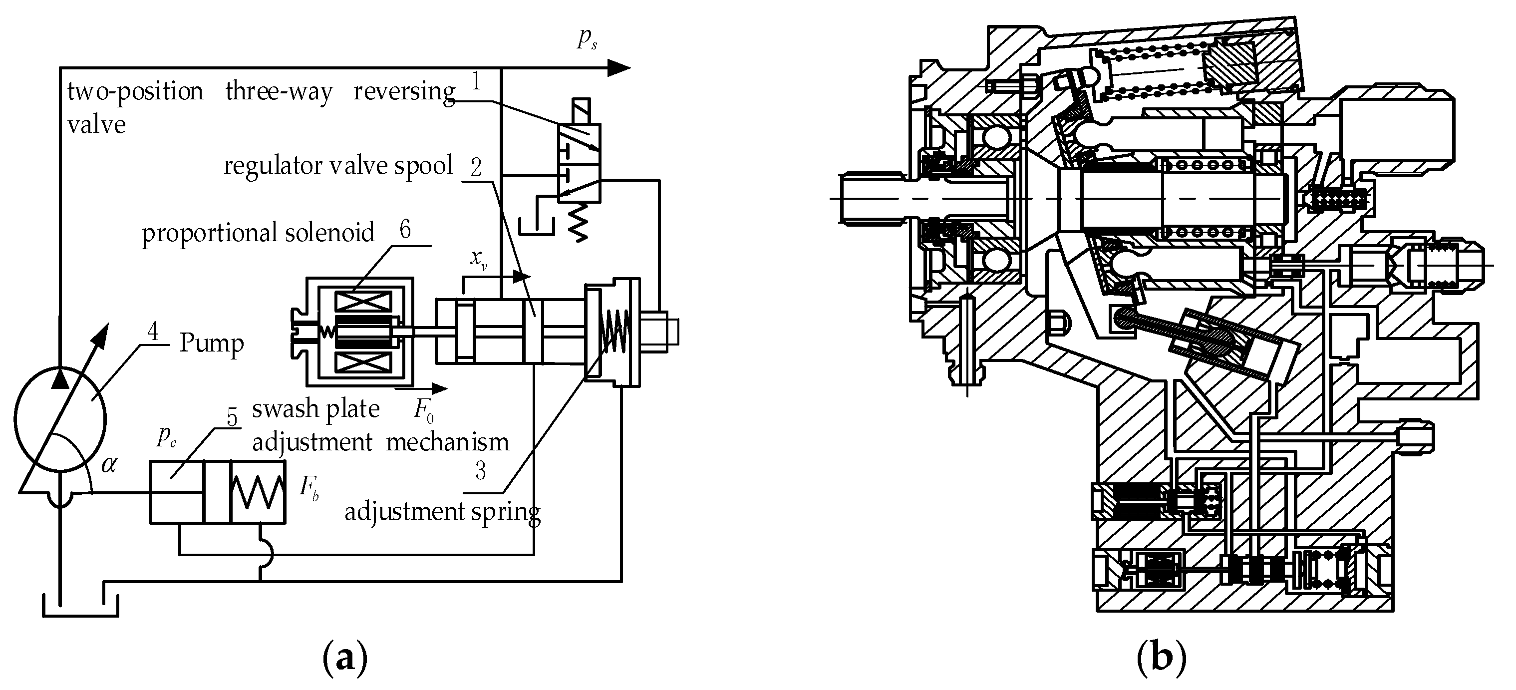
The schematic of pressure continuous regulation for EHPAAPP is shown in Figure 2a. 1 is a two-position three-way reversing valve, realizing the switch between a high-pressure and low-pressure mode. 2 is the regulator valve spool of the dual pressure variable flow pump. 3 is the adjustment spring of the pump. 5 is the swash plate adjustment mechanism. The putter of proportional solenoid 6 is connected with 2. When the continuous pressure regulation function is needed, solenoid valve 1 and proportion electromagnet 6 are powered on, resulting in a maximum compression of 3 and a thrust corresponding to the current. As the force acting on the spool by pump outlet pressure is approximately equal to the spring force minus the proportional thrust, the pump pressure is reduced as the thrust of proportional solenoid increases. This program retains the dual pressure regulation function, that is, in the case of the electromagnetic coil of proportional electromagnet cannot be energized, so original dual pressure regulation can be realized. Figure 2b is a schematic of a pressure continuous regulation electrohydraulic proportional axial piston pump.

3. Characteristic Analysis of EHPAAPP

In this section, the mathematical model of the electro-hydraulic proportional variable pump is established and its dynamic characteristics are analyzed.

3.1. Mathematical Model of the Pump

3.1.1. Model of Electro Hydraulic Proportional Regulation

The terminal voltage equation of the proportional electromagnet control coil is
u s = L d d i d t + i R s + K v d x v d t ,
where R s is internal resistance of coil and proportional control amplifier.
According to Newton’s second law, only the quality of armature components are considered, and following equation can be obtained
F 0 = K Fi i ( t τ d ) f M sgn ( d i d t ) + F r .

3.1.2. Model of the Pump Section

Summing forces in the positive direction and setting them to be equal to the time-rate-of-change of linear momentum of the regulator valve spool, the following equation may be generally written to describe the motion of the regulator valve spool
P s A v + F 0 = M v d 2 x v d t 2 + f d x v d t + K s ( x v + x 0 ) + F s t .
Based on assumptions that the fluid pressure within the control chamber is homogeneous throughout, and that the fluid inertia and viscous effects within this chamber are negligible compared to the hydrostatic pressure effects of the fluid, the fluid pressure within the control actuator is modeled with the following equation
V c β d p c d t = Q c + A c L d α d t .
The volumetric flow-rate into the control actuator can be expressed as
Q c = { C d W ( u x v ) 2 ρ P c x m   < x v < u C d W ( u + x v ) 2 ρ ( P s P c ) C d W ( u x v ) 2 ρ ( P s P c ) u   x v u C d W ( u + x v ) 2 ρ ( P s P c ) u < x v < x m .
The equation of motion for the swash-plate may be written as
I d 2 α d t 2 = c d α d t + F b L F c L n = 1 n F n L .
The equation of motion for the control actuator can be written as follows
M c d 2 x c d t 2 = F c cos α P c A c ,
where the displacement of the control chamber x c can be written as
x c = L tan α ,
and it can be obtained that
F c = M c L d 2 α d t 2 + P c A c .
The equation of motion for the nth piston as it moves in the x-direction may be written as
M p d 2 x n d t 2 = F n cos α P n A p ,
where x n = r tan α sin θ .
So the following formula is obtained
F n = M p r sin θ d 2 α d t 2 + 2 M p r cos θ ω d α d t M p r sin θ ω 2 α + P n A p .
Substituting the above-mentioned force expression into Equation (6), the following intermediate result is produced,
[ I + M c L 2 + M p r 2 N 2 ] d 2 α d t 2 + c d α d t ( k b L 2 + N 2 M p r 2 ω 2 ) α = ( F b P c A c ) A p r n = 1 N P n sin θ .
The pressure of each piston has been studied numerically and has been shown to be fairly constant while the pistons are located directly over the intake and discharge ports, and that the pressure changes almost linearly as the pistons pass over the transition slots on the valve plate. Because this is so common, the fluid pressure within the nth piston bore is usually described using the pressure profile shown in Figure 3. In this figure the average transition-angle on the valve plate is shown by the symbol γ, which is normally called the pressure carryover-angle. Using Figure 3, the following discrete representation for the fluid pressure within the nth piston bore may be written
P n = { P d π 2 + γ < θ < π 2   P d ( P d P i ) γ ( θ π / 2 ) π 2 < θ < π 2 + γ P i π 2 + γ < θ < 3 π 2 P i + ( P d P i ) γ ( θ 3 π / 2 ) 3 π 2 < θ < 3 π 2 + γ   .
Because the oscillation frequency of the force is much higher than for the pump system, it is sufficient to consider the average effect for the whole system.
Summarize the analysis for the swash-plate dynamics produces the following result:
( I + M c L 2 + M p r 2 Z 2 ) d 2 α d t 2 + c d α d t + ( k b L 2 + Z 2 M p r 2 ω 2 ) α = A p r γ Z 2 π P s A c L P c + F b L .
Based upon similar assumptions are is used to derive Equation (4), the fluid pressure within the discharge actuator may be modeled with the following equation
V h β d P s d t = Q p Q d K P s .
For a pump with a fixed input-speed, the volumetric flow-rate generated by the pump is often expressed as
Q p = G p α ,
where G p = Z A p r ω π .
The system expression is:
{ x ˙ 1 = Z A p r ω β π V h x 2 k β V h x 1 x ˙ 2 = x 3 x ˙ 3 = k b L 2 + Z 2 m p r 2 ω 2 I + m c L 2 + Z 2 m p r 2 x 2 c I + m c L 2 + Z 2 m p r 2 x 3 Z 2 π A p r γ I + m c L 2 + Z 2 m p r 2 x 1 A c L I + m c L 2 + Z 2 m p r 2 x 4 + F b L I + m c L 2 + Z 2 m p r 2 x ˙ 4 = A c L β V c x 2 + Q c x ˙ 5 = x 6 x ˙ 6 = 1 m v ( p s A v + F 0 f v d x v d t K s ( x v + x 0 ) F s t ) ,
and the state vector is X = [ α   α ˙   p s   p c   x v   x ˙ v ] T .

3.2. Response Analysis of the Pump

Based on consideration of each subsystem, a mathematical model of pressure continuous regulation for EHPAAPP is established, the dynamic response graph is obtained by MATLAB simulation. The main parameters selected are shown in Table 1, the maximum input current of the electromagnet is 3.3 A, and the maximum output force of the electromagnet is 170 N.
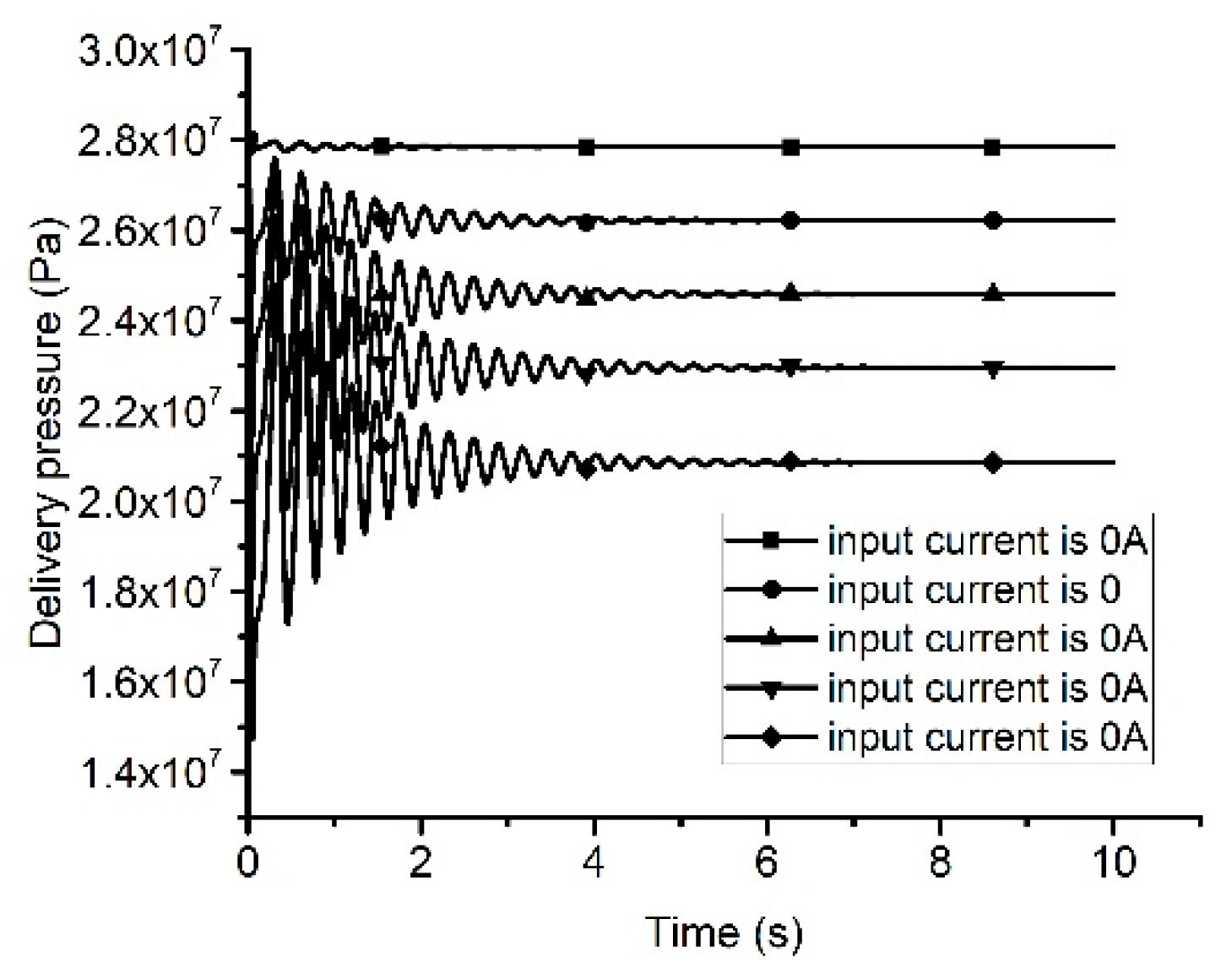
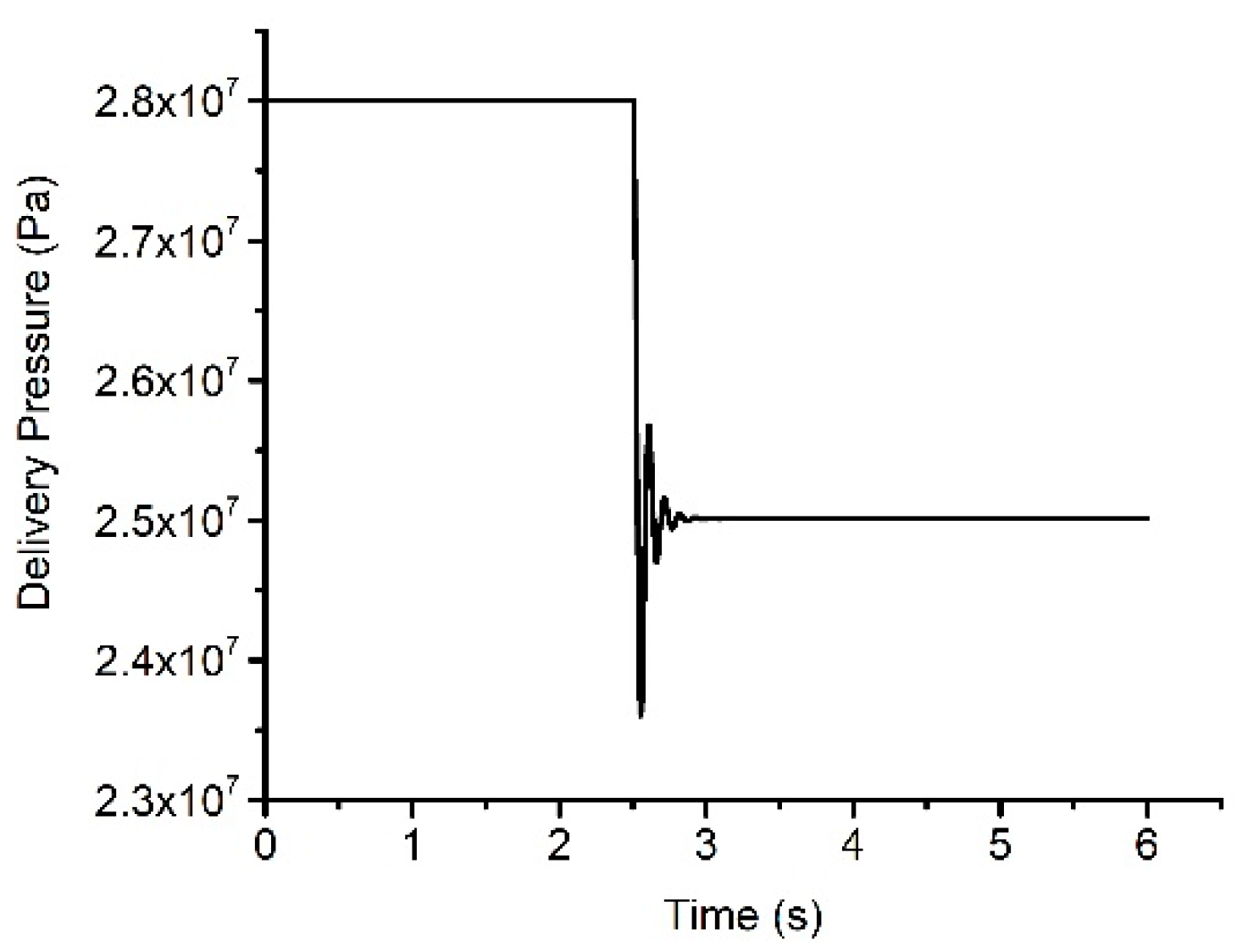
The input is the current signal of proportional solenoid, and the output is the pressure of the pump. The input current changes from 0 A to 2 A. It can be seen from Figure 4 that the pressure of the system can reach the setting value of pressure when the current signal value changes, but there are big shocks with pressure value of 4.5 MPa. The pressure value of the variable pump undergoes the oscillation regulation process, and finally stabilizes at the third second and instantaneous peak pressure exceeds 125% of the rated outlet pressure.
Therefore, a pressure controller should be designed to achieve the pressure control requirements of the hydraulic pump in the case of a wide range of circumstances of external load and system parameters.

4. Control Method Design of the Pump

4.1. PID Control Method

A PID controller (proportional-integral-derivative controller) is a common feedback loop component in industrial control applications. It consists of proportional unit P, integral unit I and differential unit D which is simple and no precise system model is needed for its use.
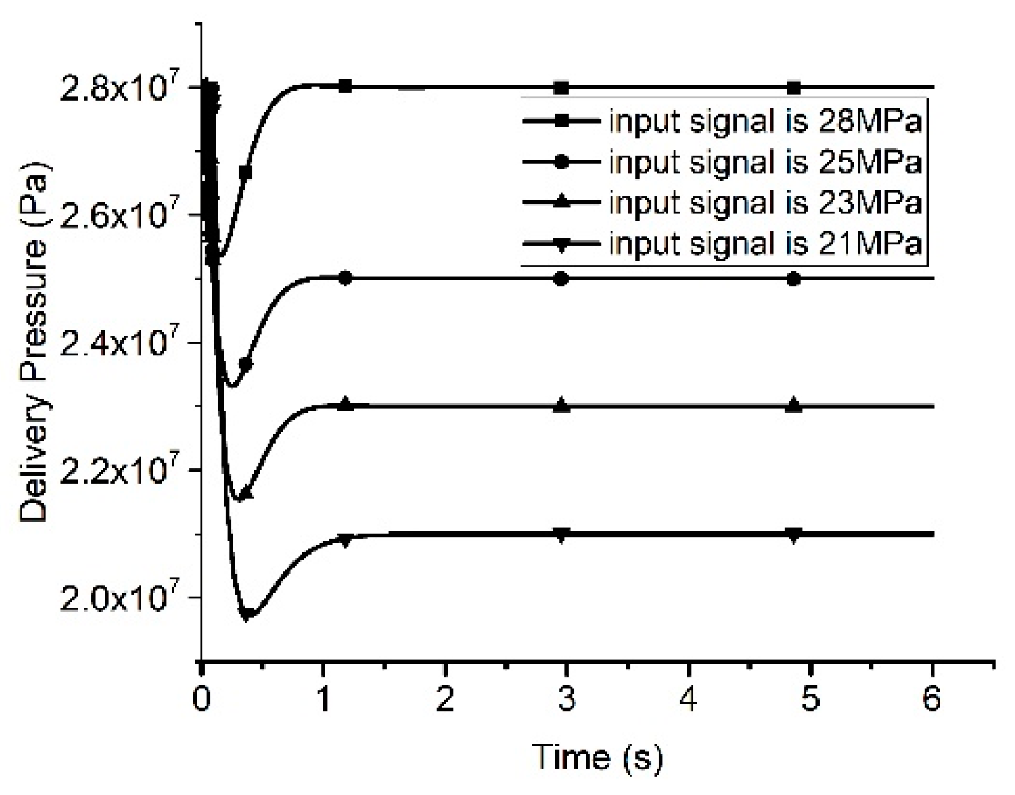
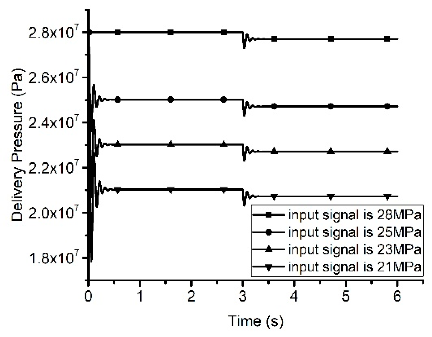
Figure 5 shows the corresponding situation of the pressure command signal from 28 MPa to 21 MPa. The pressure value is stable after about 1 s, and the maximum overshoot is 21 MPa.
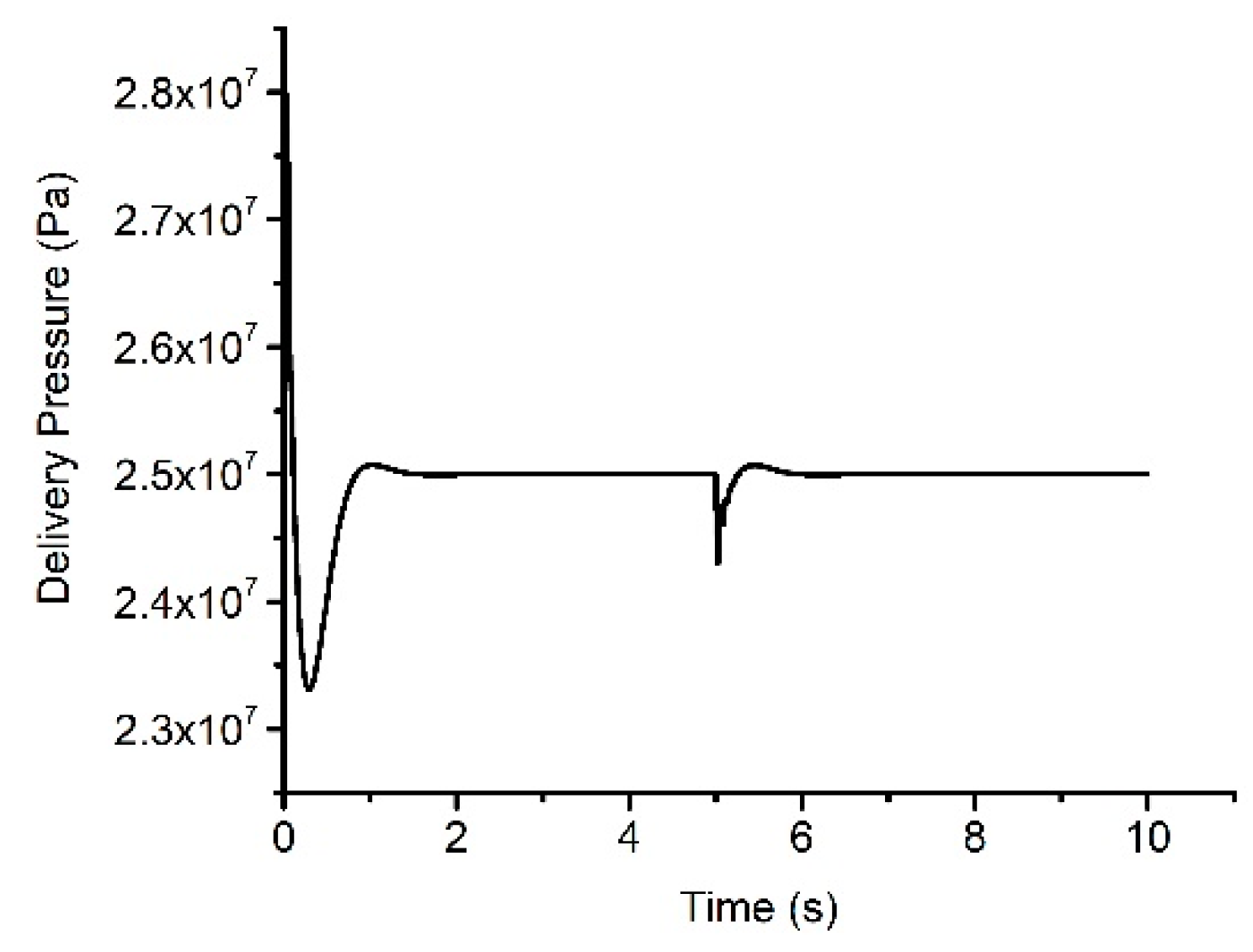
The situation of flow changes little in the process of pressure control, the pressure response is shown in the Figure 6 below.
As seen from Figure 6, there is flow disturbance at the fifth second and the pressure command signal is 25 MPa. The pressure value is stable after about 1 s, and the error with the command pressure is 0.2 MPa after flow disturbance.

4.2. LQR Control Method

Seen from the established mathematical model of the pump, it has a very complicated and high degree of nonlinearity. Although the pump can acquire the more satisfactory dynamic performance and control accuracy, it is difficult to ensure the desired performance when the system parameters change with working conditions.
Precise linearization methods are considered because of the existence of nonlinear components in this system, and the control strategy for the system is designed after precise linearization.
The following definitions are used:
a 1 = Z A p r ω β π V h   a 2 = k β V h   b 1 = k b L 2 + Z 2 m p r 2 ω 2 I + m c L 2 + Z 2 m p r 2   b 2 = c I + m c L 2 + Z 2 m p r 2   b 3 = Z 2 π A p r γ I + m c L 2 + Z 2 m p r 2 b 4 = A c L I + m c L 2 + Z 2 m p r 2   b 5 = F 0 L I + m c L 2 + Z 2 m p r 2   c 1 = A c L β V c   d 1 = A c L β V c d 2 = { β V c ( c d ϖ U 2 ρ x 4 ) x m   < x v < u β V c ( c d ϖ U 2 ρ ( x 1 x 4 ) c d ϖ U 2 ρ x 4 ) u   x v u β V c ( c d ϖ U 2 ρ ( x 1 x 4 ) ) u < x v < x m d 3 = { β V c ( c d ϖ 2 ρ x 4 ) x m   < x v < u β V c ( c d ϖ 2 ρ ( x 1 x 4 ) c d ϖ U 2 ρ x 4 ) u   x v u β V c ( c d ϖ 2 ρ ( x 1 x 4 ) ) u < x v < x m .
So, the simplified mathematical model is:
{ x ˙ = f ( x ) + g ( x ) y = h ( x ) ,
where f ( x ) = { a 1 x 2 a 2 x 1 x 3 b 1 x 2 b 2 x 3 b 3 x 1 b 4 x 4 + b 5 d 1 x 2 + d 2 and g ( x ) = [ 0   0   0   d 3 ] T .
Whether the obtained pump outlet pressure equation satisfies the precise linearization condition should be verified first. The r 1 order Li is the derivative of pump outlet pressure output in the directions of f ( x ) and g ( x ) respectively.
The calculation result of each order Li derivative is:
L f 1 h ( x ) = a 1 x 1 a 2 x 1 L f 2 h ( x ) = a 1 x 3 a 1 a 2 x 2 + a 2 2 x 3 L f 3 h ( x ) = ( a 2 3 a 1 b 3 ) x 1 ( a 2 2 a 1 b 1 a 1 ) x 2 ( a 1 a 2 + a 1 b 2 ) x 3 a 1 b 4 x 4 + a 1 b 5 L g 1 L f 1 h ( x ) = 0 L g 1 L f 2 h ( x ) = 0 L g 1 L f 3 h ( x ) = a 1 b 4 d 2 0 .
The relative degree of the system is 4, which is equal to the number of system state variables, and the described system equations can be complete linearization.
It is proposed to adopt a linear optimal state regulator (LQR) method with quadratic performance indicators. This is because the solution of the optimal state regulator has a unified analytical expression, and a simple linear state feedback control law can be obtained. It is easy to implement feedback control, and it has a good engineering realization.
The quadratic performance index of the system is:
J z = 1 2 0 ( Z T Q z Z + v 1 T R z v 1 ) d t .
The corresponding optimal control expression is:
v = R z 1 B T P z Z b = K Z b = k 1 z 0 k 2 z 1 k 3 z 2 k 4 z 3 .
P z is non-singular symmetric coefficient matrix, and satisfy the equation
A T P z + P z A P B R z 1 B 1 T P z + Q z = 0 ,
Figure 7 shows the corresponding situation of the pressure command signal from 28 MPa to 25 MPa. The pressure value is stable after about 0.5 s, and the maximum overshoot is 0.15 MPa.
The situation of flow suddenly changes greatly in the process of pressure control, the discharge pressure response is shown in the figure below.
As seen from the Figure 8, the pressure command signal is 28 MPa to 21 MPa, and there are flow disturbance at the third second. The pressure value is stable after about 0.5 s, and the overshoot is 0.5 MPa. Under the condition of flow interference at the third second, the error between final pump outlet pressure and the command pressure is 0.2 MPa.
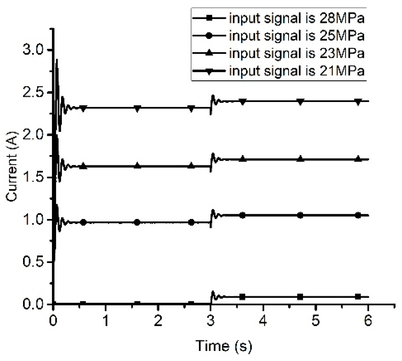
The Figure 9 shows the corresponding current change. The change trend is opposite to the pressure change trend. When the current increases, the pump outlet pressure value decreases, which proves the accuracy of the control method.

4.3. Backstepping Sliding Control Method

The steps of designing the backstepping sliding mode control method for pressure tracking of the pump are as follows:
Step1. According to the pump outlet pressure x 1 and the command signal x 1 d , the tracking error of the system is defined as:
e 1 = x 1 x 1 d .
After derivation the above pressure error, then,
e ˙ 1 = x ˙ 1 x ˙ 1 d = a 1 x 2 a 2 x 1 x ˙ 1 d .
Define the Lyapunov function of the first state variable of the system as,
V 1 = 0.5 e 1 2 .
Derivation the Lyapunov function of the first state variable of the system,
v ˙ 1 = e 1 e ˙ 1 = e 1 ( x ˙ 1 x ˙ 1 d ) = e 1 ( a 1 x 2 a 2 x 1 x ˙ 1 d ) .
Let x 2 = 1 a 1 ( c 1 e 1 a 2 x 1 x ˙ 1 d ) + e 2 , if c 1 > 0 . e 2 is virtual controller, then
e 2 = x 2 + 1 a 1 ( c 1 e 1 a 2 x 1 x ˙ 1 d ) .
Substituting it into the above formula and then:
V ˙ 1 = c 1 e 1 2 + a 1 e 1 e 2 .
At this condition, if e 2 = 0 and then V ˙ 1 0 , the stability of Lyapunov is satisfied under these conditions. In order to make e 2 = 0 , the next design is needed.
Step 2. Define the Lyapunov function of the second state variable of the system as:
V 2 = V 1 + 0.5 e 2 2 .
Substitute e 2 = x 2 + 1 a 1 ( c 1 e 1 a 2 x 1 x ˙ 1 d ) and the state space equation of x 2 into the above equation, and then:
V ˙ 2 = c 1 e 1 2 + a 1 e 1 e 2 + e 2 ( x 3 + a 2 2 a 1 x 1 a 2 x 2 1 a 1 x ¨ 1 d + 1 a 1 c 1 e ˙ 1 ) .
Let
x 3 = a 2 2 a 1 x 1 + a 2 x 2 + 1 a 1 x ¨ 1 d 1 a 1 c 1 e ˙ 1 a 1 e 1 c 2 e 2 + e 3 ,
and
e 3 = a 2 2 a 1 x 1 a 2 x 2 1 a 1 x ¨ 1 d + 1 a 1 c 1 e ˙ 1 + a 1 e 1 + c 2 e 2 + x 3 ,
V ˙ 2 = c 1 e 1 2 c 1 e 2 2 + e 2 e 3 .
At this condition, if e 3 = 0 and then V ˙ 2 0 , the stability of Lyapunov is satisfied under these conditions. In order to make e 3 = 0 , the next design is needed.
Step 3. Define the Lyapunov function of the third state variable of the system as:
V 3 = V 2 + 0.5 e 3 2 .
Derivation the Lyapunov function of the third state variable of the system, then
V ˙ 3 = V ˙ 2 + e 3 e ˙ 3 = c 1 e 1 2 c 2 e 2 2 + e 2 e 3 + e 3 e ˙ 3 ,
Substitute e 3 and the state space equation of x 3 into the above equation, and then
V ˙ 3 = c 1 e 1 2 c 2 e 2 2 c 3 e 3 2 + e 3 ( ( b 1 + a 2 2 ) x 2 + ( b 2 a 2 ) x 3 + ( b 3 a 2 2 a 1 ) x 1 + b 4 x 4 + b 5 1 a 1 x 1 d + c 1 a 1 e ¨ 1 + a 1 e ˙ 1 + c 2 e ˙ 2 )
Letbe
x 4 = 1 b 4 ( ( b 1 + a 2 2 ) x 2 + ( b 2 a 2 ) x 3 + ( b 3 a 2 2 a 1 ) x 1 + b 5 1 a 1 x 1 d + c 1 a 1 e ¨ 1 + a 1 e ˙ 1 + c 2 e ˙ 2 + e 2 + c 3 e 3 ) + e 4 ,
Then
V ˙ 3 = c 1 e 1 2 c 2 e 2 2 c 3 e 3 2 + b 4 e 3 e 4 ,
At this condition, if e 4 = 0 and then V ˙ 3 0 , the stability of Lyapunov is satisfied under these conditions. In order to make e 4 = 0 , the next design is needed.
Step 4. Define the Lyapunov function of the last state variable of the system as:
V 4 = V 3 + 0.5 σ 2 ,
where
σ = k 1 e 1 + k 2 e 2 + k 3 e 3 + e 4 .
Let
S = 1 b 4 [ ( b 1 + a 2 2 ) x 3 + ( b 3 a 2 3 a 1 ) ( a 1 x 2 a 2 x 1 ) + ( b 2 a 2 ) ( b 1 x 2 + b 2 x 3 + b 3 x 1 + b 4 x 4 + b 5 ) 1 a 1 x 1 d + c 1 a 1 e 1 + a 1 e ¨ + c 2 e ¨ 2 + e ˙ 2 + c 3 e ˙ 3 ] .
Then the input of the system can be obtained
u = 1 d 2 ( k 1 e ˙ 1 + k 2 e ˙ 2 + k 3 e ˙ 3 d 1 x 3 d 3 S h ( σ + β sgn ( σ ) ) ) .
Substitute e 4 and the state space equation of x 4 into the above equation, and then
V ˙ 4 = c 1 e 1 2 c 2 e 2 2 c 3 e 3 2 + b 4 e 3 e 4 h σ 2 h β | σ | ,
where h 2 , β 2 are positive constants. Let
Q = [ h k 1 2 + c 1 h k 1 k 2 h k 1 k 3 h k 1 h k 1 k 2 h k 2 2 + c 2 h k 2 k 3 h k 2 h k 1 k 3 h k 2 k 3 h k 3 2 + c 3 h k 3   h k 1 h k 2 h k 3 h ] ,
and
e T Q e = [ e 1 e 2 e 3 e 4   ] [ h k 1 2 + c 1 h k 1 k 2 h k 1 k 3 h k 1 h k 1 k 2 h k 2 2 + c 2 h k 2 k 3 h k 2 h k 1 k 3 h k 2 k 3 h k 3 2 + c 3 h k 3   h k 1 h k 2 h k 3 h ] [ e 1 e 2 e 3 e 4 ] = ( h k 1 + c 1 ) e 1 2 + ( h k 2 + c 2 ) e 2 2 + ( h k 3 + c 3 ) e 3 2 + h e 4 + 2 h k 1 k 2 e 1 e 2 + 2 h k 1 k 3 e 1 e 3 + 2 h k k 1 e 1 e 4 + 2 h k 2 k 3 e 2 e 3 + 2 h k 2 e 2 e 4 + 2 h k 3 e 3 e 4
Therefore,
V ˙ 4 = e T Q e h β | σ | ,
and
| Q | = h c 1 c 2 c 3 + h 2 b 4 c 1 c 2 k 3 ,
| Q | > 0 can be realized by taking the value of h 2 , k 2 , k 3 , so that Q is a positive definite matrix and V ˙ 4 0 .
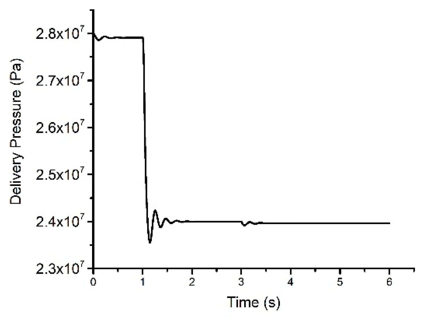
As seen from the Figure 10, the pressure command signal is 28 MPa to 24 MPa, and there is flow disturbance at the third second. The pressure value is stable after about 0.5 s, and the overshoot is 0.3 MPa. Under the condition of flow interference at the third second, the error between final pump outlet pressure and the command pressure is 0.15 MPa.
The Figure 11 shows the corresponding current change. The change trend is opposite to the change trend of delivery pressure. When the current increases, the pump outlet pressure value decreases, which proves the accuracy of the control method. When the delivery pressure is 28 MPa, the corresponding current value is 0A, and when the current is about 1.4 A, the outlet pressure of the pump is 24 MPa.
The calculated current value varies with changes in pump outlet pressure. The current value is stable after about 0.5 s, and the overshoot is 0.1 A. Under the condition of flow interference at the third second, the error is very small with the value about 0.05A.

5. Conclusions

The analysis of EHPAAPP and the simulation results of this paper supports the following conclusions:
The principle of pressure continuous regulation electrohydraulic proportional axial piston pump was proposed. The structure is relatively simple, and the dual pressure regulation feature is retained. A contribution of this work lies in system modeling in terms of freebody diagrams of the components of the piston group together with the proportional electromagnet.
The PID control method, LQR based on feedback linearization method and backstepping sliding control method were designed to control the system. The effectiveness of the control methods were verified by the MATLAB simulation platform, showed that the delivery pressure of the pump could accurately track the system input signal and the out-of-system interference such as sudden changes of flow and so on. On the other hand, control law has a great influence on system control. More efficient control law needs to be carried out.

Author Contributions

P.Z. carried out the design of the control law, modeling and simulation; and Y.L. conceived the concept of the control strategies of the aviation axial piston pump.

Funding

The two funders of this paper are National Natural Science Foundation of China (Grant no. 51475019) and National Key Basic Research Program of China (Grant no. 2014CB046403).

Acknowledgments

Authors would like to thank for the support of National Natural Science Foundation of China (Grant no. 51475019) and National Key Basic Research Program of China (Grant no. 2014CB046403).

Conflicts of Interest

The authors declare no conflict of interest. The funders had no role in the design of the study; in the collection, analyses, or interpretation of data; in the writing of the manuscript; or in the decision to publish the results.

Nomenclature

A c cross-sectional area of the control actuator
A p cross-sectional area of a single piston within the pump
A v cross-sectional area of the spool valve
c effective viscous-drag coefficient for the swash plate
C d valve discharge-coefficient
F b compressed force of the bias-spring when the swash-plate angle is zero
F c force exerted on the swash-plate by the bias actuator
f M force of electromagnetic hysteresis
F n reaction force between the nth piston-slipper assembly and the swash plate
F 0 axial thrust of the armature
F r coulomb friction
F s p steady-state fluid force of the valve
G p pump flow-gain
I mass moment-of-inertia for the swash-plate
i input current of proportional electromagnet
K pump-leakage coefficient
k b spring rate for the bias-spring
K F i current-force gain
K s spring rate for the valve-spring
K v coil induced back EMF coefficient
L fixed moment-arm for the bias and control actuators
instantaneous moment-arm for the control actuator
instantaneous moment-arm for the nth piston-slipper assembly
L d coil inductance
M c mass of the control actuator
M p mass of a single piston within the pump
P c control pressure
P s pump discharge pressure
P i pump intake-pressure
P n instantaneous pressure within the nth piston chamber
Q c volumetric flow-rate into the control actuator
Q d volumetric flow-rate being drawn from the discharge line by the system load
Q p volumetric flow-rate from the pump
r piston-pitch radius within the pump
R s internal resistance of coil and proportional control amplifier
u underlapped dimension for the open-centered spool valve
u s input voltage of the coil
V c nominal volume of the control actuator
Vhvolume of the discharge line
W area gradient of valve port
x v displacement of the spool valve
x c displacement of the control actuator
x m limit displacement of the spool
x n displacement of the nth piston-slipper assembly
τ delay time
Z number of pistons within the pump
α swash-plate angle
β fluid bulk modulus-of-elasticity
γ valve plate pressure carryover-angle
θ angular displacement of the nth piston
ρ fluid mass-density
ω input shaft-speed for the pump
EHPAAPPelectrohydraulic proportional aviation axial piston pump

References

  1. Li, Y.J. Aircraft Hydraulic Transmission and Control; Science Press: Beijing, China, 2009; pp. 10–13. [Google Scholar]
  2. Wang, Z.L. Aircraft High Pressure Energy System; Beihang University Press: Beijing, China, 2004; pp. 11–15. [Google Scholar]
  3. Spencer, J.E. Development of variable pressure hydraulic systems for military aircraft utilising the smart hydraulic pump. Proc. Inst. Mech. Eng. Part H 1993, 6, 101. [Google Scholar]
  4. Wang, S.P.; Tomovic, M.; Liu, H. Commercial Aircraft Hydraulic System; Shanghai Jiao Tong University Press: Shanghai, China, 2015; pp. 186–190. [Google Scholar]
  5. Ouyang, X.-P.; Li, L.; Fang, X.; Yang, H.-Y. Dynamic characteristics of dual-pressure switch for aircraft piston pump. J. Zhejiang Univ. (Eng. Sci.) 2016, 50, 397–404. [Google Scholar]
  6. Lu, N.; Fu, Y.L.; Sun, X.X. Digital modeling of double press axial piston pump and its thermal analysis basing on AMEsim. J. Beihang Univ. 2006, 32, 1055–1058. [Google Scholar]
  7. Peter, T. Microprocessor Control of Aerospace Hydraulic Pumps; SAE Tcch. Pap. Ser. 871863; SAE: Warrendale, PA, USA, 1987. [Google Scholar]
  8. Hupp, R.V.; Haning, R.K. Power efficient hydraulic system. Rockwell International (1988). Vol.1 (Research) ADA203900.
  9. Hupp, R.V.; Haning, R.K. Power Efficient Hydraulic System. Rockwell International (1988), vol.1 (Experiment) ADA203900.
  10. Huang, B.; Wang, S.; Meng, Y.; Shi, J. Energy-saving optimization for intelligent pumps based on performance reliability restriction. J. Beihang Univ. 2013, 4, 559–563. [Google Scholar]
  11. Lu, L.; Tang, Z.; Li, H.; Pei, Z. Fuzzy PID control of intelligent pump. In Proceedings of the 2011 International Conference on IEEE Fluid Power and Mechatronics (FPM), Beijing, China, 17–20 August 2011; pp. 803–808. [Google Scholar]
  12. Song, X.D.; Yao, X.X.; Gong, Z.B. Model reference adaptive control for variable pressure pumping source. J. Beijing Inst. Technol. 2011, 31, 944–948. [Google Scholar]
  13. Li, H.; Tang, Z.Y.; Pei, Z.C.; Peng, J. PID control of airbone intelligent pump system. Mach. Tool Hydraul. 2010, 38, 97–98. [Google Scholar]
  14. Fiebing, C.; Xiujuan, L.; Smolka, S. Pressure compensator (PC) pressure overshoot analysis and experimental research of an open circuit pump. In Proceedings of the IEEE 2015 International Conference on Fluid Power and Mechatronics (FPM), Harbin, China, 5–7 August 2015; pp. 910–913. [Google Scholar]
  15. Achten, P. Dynamic high-frequency behaviour of the swash plate in a variable displacement axial piston pump. Proc. Inst. Mech. Eng. Part I J. Syst. Control Eng. 2013, 227, 529–540. [Google Scholar] [CrossRef]
  16. Manring, N.D.; Mehta, V.S. Physical limitations for the bandwidth frequency of a pressure controlled, axial-piston pump. J. Dyn. Syst. Meas. Control 2011, 133, 061005. [Google Scholar] [CrossRef]
  17. Mandal, N.P.; Saha, R.; Mookherjee, S.; Sanyal, D. Pressure compensator design for a swash plate axial piston pump. J. Dyn. Syst. Meas. Control 2014, 136, 021001. [Google Scholar] [CrossRef]
  18. Kemmetmüller, W.; Fuchshumer, F.; Kugi, A. Nonlinear pressure control of self-supplied variable displacement axial piston pumps. Control Eng. Pract. 2009, 18, 84–93. [Google Scholar] [CrossRef]
  19. Wang, S. Generic Modeling and Control of an Open-Circuit Piston Pump—Part I: Theoretical Model and Analysis. J. Dyn. Syst. Meas. Control 2016, 138, 041004. [Google Scholar] [CrossRef]
  20. Wang, S. Generic Modeling and Control of an Open-Circuit Piston Pump—Part II: Control Strategies and Designs. J. Dyn. Syst. Meas. Control 2016, 138, 041005. [Google Scholar] [CrossRef]
  21. Koivumäki, J.; Mattila, J. Adaptive and nonlinear control of discharge pressure for variable displacement axial piston pumps. J. Dyn. Syst. Meas. Control 2017, 139, 101008. [Google Scholar] [CrossRef]
  22. Wei, J.; Guo, K.; Fang, J.; Tian, Q. Nonlinear supply pressure control for a variable displacement axial piston pump. Proc. Inst. Mech. Eng. Part I: J. Syst. Control Eng. 2015, 229, 614–624. [Google Scholar] [CrossRef]
  23. Castañeda, L.A.; Luviano-Juárez, A.; Chairez, I. Robust trajectory tracking of a delta robot through adaptive active disturbance rejection control. IEEE Trans. Control Syst. Technol. 2015, 23, 1387–1398. [Google Scholar] [CrossRef]
  24. Chen, C. Backstepping control design and its applications to vehicle lateral control in automated highway systems. Ph.D. Thesis, University of California, Berkeley, CA, USA, 1996. [Google Scholar]
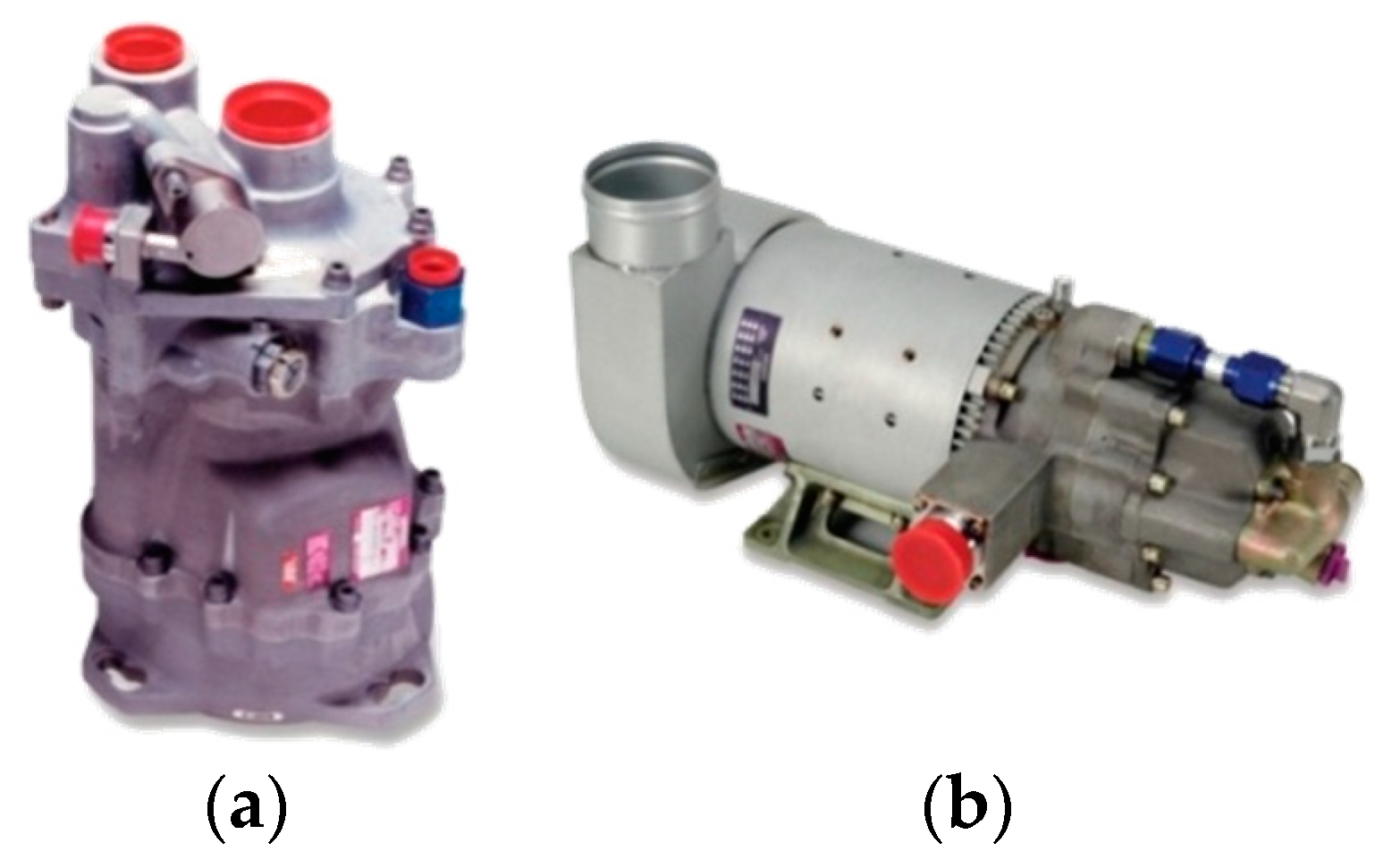
Figure 1. (a) Aircraft engine driven pump; (b) Aircraft engine motor driven pump.
Applsci 09 01376 g001
Figure 2. (a) Program of a pressure continuous regulation for EHPAAPP; (b) Schematic of a pressure continuous regulation for EHPAAPP.
Applsci 09 01376 g002
Figure 3. Pressure profile for illustrating the essential characteristics of delivery pressure.
Applsci 09 01376 g003
Figure 4. The delivery pressure of EHPAAPP in the case of different current signals.
Applsci 09 01376 g004
Figure 5. The delivery pressure of EHPAAPP in the case of different input signals with proportional integral derivative (PID) control method.
Applsci 09 01376 g005
Figure 6. The delivery pressure of EHPAAPP with PID controller in the case of input signal is 25 MPa with flow disturbance at the fifth second.
Applsci 09 01376 g006
Figure 7. The delivery pressure of EHPAAPP with linear quadratic regulator (LQR) method in the case of input signal change from 28 MPa to 25 MPa.
Applsci 09 01376 g007
Figure 8. The delivery pressure of EHPAAPP with LQR method in the case of different input pressure signal with flow disturbance at the third second.
Applsci 09 01376 g008
Figure 9. Current Response of EHPAAPP with the LQR method in the case of a different input signal with flow disturbance at the third second.
Applsci 09 01376 g009
Figure 10. The delivery pressure of EHPAAPP with backstepping sliding control method in the case of input signal change from 28 MPa to 24 MPa with flow disturbance.
Applsci 09 01376 g010
Figure 11. Current Response of EHPAAPP with backstepping sliding control method in the case of input signal change from 28 MPa to 24 MPa with flow disturbance.
Applsci 09 01376 g011
Table 1. The table of main parameters.
SymbolValueUnit
K 4.55 × 10⁻² m 3 / ( Pa s )
β 1000 MPa
V h 3.5 × 10⁻³ m 3
N 9Null
A p 265 × 10−6 m 2
A c 150 × 10−6 m 2
A v 12.5 × 10⁻⁶ m 2
L 60 mm
I 1.15 × 10² kg m 2
K q 2.85 × 101 m 2 / s
K c 2.14 × 10¹¹ m 3 / ( Pa s )
k 20 N / m m