3.1. Influence of Numerical Aperture on Focusing Situation in Glass
Optical microscope was used to observe the side view of molten area in the scanning direction of laser beam, as shown in
Figure 7. The laser beam was tightly focused inside glass by objective lens of N.A. of 0.65 with spherical aberration correction. The pulse repetition rate, scanning velocity, and pulse energy were 1.0 MHz, 100 mm/s, and 1.5 µJ, respectively. As can be seen from the figure, the starting point of laser absorption was created when an ultrashort pulsed laser beam was tightly focused inside the glass, and the absorption area was expanded by the upward movement of the absorption point. Then, this absorption point was dropped down and shifted to the right side to complete the first cycle of molten area formation, and new starting point of laser absorption was established. The process was repeated periodically, and the welding lines were created. Therefore, molten area was not created by only one laser shot, but by the sum of multiple laser shots [
19]. It is considered that the focusing condition such as numerical aperture has a great influence on this phenomenon, which is strongly related to the absorbed energy of the laser beam.
The results of ray tracking are shown in
Figure 8a,b. The most centralized part in the path of ray tracking was defined as the spot, and the distance between upper intersection point and bottom intersection point in laser beam axis was determined as the elongation distance of spot
d1 +
d2. It can be seen from
Figure 8a that
d1 +
d2 was equal to 0 for each numerical aperture in air, and higher numerical aperture resulted in diffusion of laser beam.
Figure 8b shows that rays of laser beam of each numerical aperture passed through the interface between air and glass. Then, the angle of ray changed because of a different refractive index at the interface between air and glass, according to the Snell’s law. It can be seen that rays of laser beam did not intersect at one point, which indicated that the laser beam could not be focused in glass the same way as that in air. The value of
d1 +
d2 was smaller, when numerical aperture was lower, such as 0.45. This result showed that the distance of high power density in laser beam axis was shorter, and it was difficult to maintain absorption of laser energy. However, the rays of laser beam in laser irradiation direction diffused evidently, when the numerical aperture was higher. Therefore, higher numerical aperture indicated that the focusing situation was more likely to be disturbed. This is because higher numerical aperture such as 0.85 resulted in larger angle of incidence, and thus larger angle of refraction. This phenomenon caused loose focusing situation in glass and thus the reduction of power density. Thus, it can be considered that the spot diameter in glass would be decreased with increasing numerical aperture. N.A. of 0.65 showed superior focusing characteristics when compared with N.A. of 0.45 and 0.85, which enables achievement of stable welding of glass. The measurement results of spot diameter and absorption rate for various numerical apertures are discussed in subsequent sections.
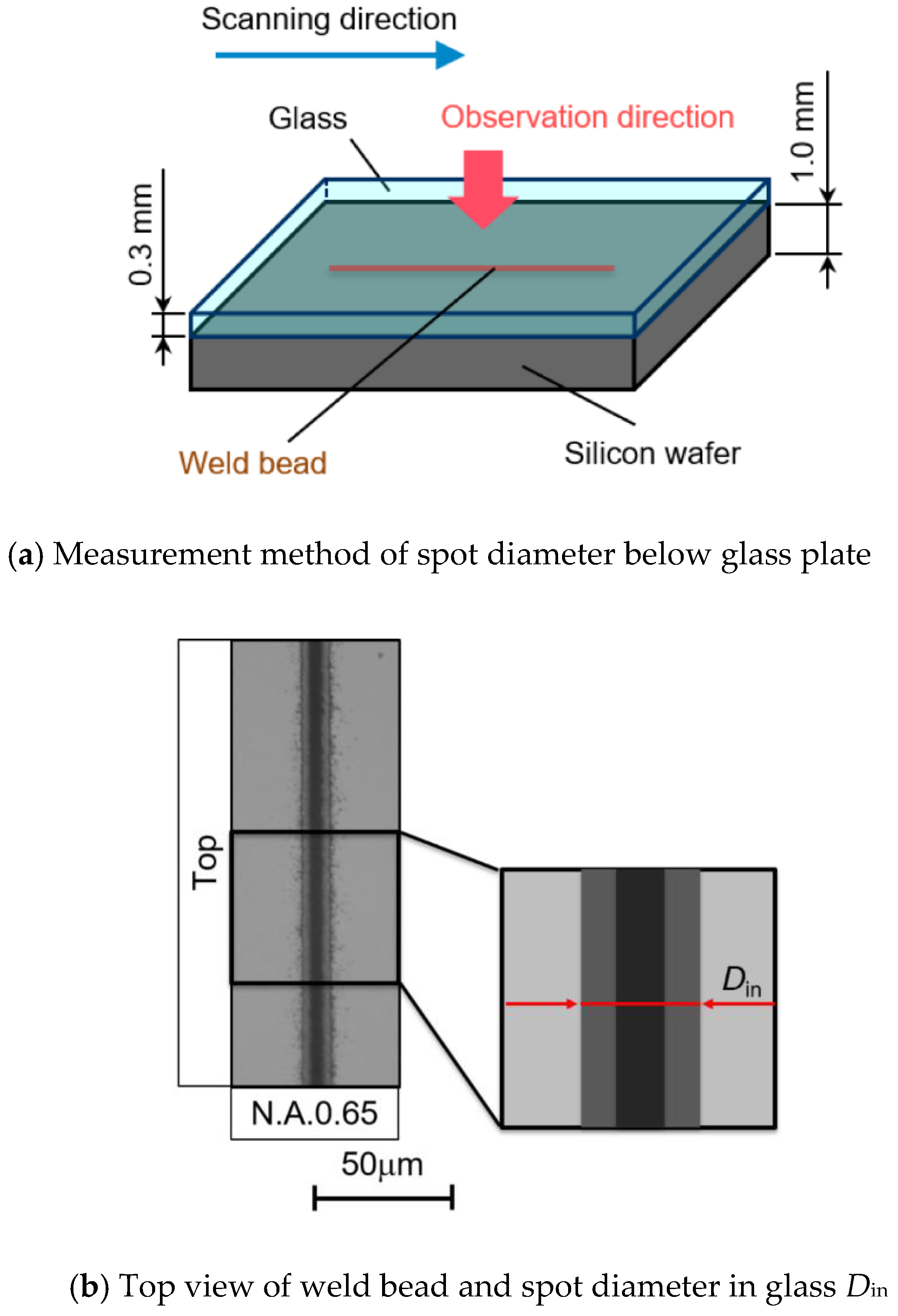
Figure 9 shows the measurement results of laser spot focused in glass. As shown in
Figure 9a, the glass plate of 0.3 mm thickness and monocrystalline silicon wafer of 1.0 mm thickness were placed together by optical contact, and then laser beam was focused and scanned around the interface of these two materials from the glass plate side. The top view of the formed weld bead in the case of N.A. of 0.65 and the definition of spot diameter in glass
Din are shown in
Figure 9b,c shows the measurement results of spot diameter in glass
Din, spot diameter in air
Ds and spot expansion ratio
Din/
Ds with various numerical apertures.
Din/
Ds is the ratio of spot diameter in glass and spot diameter in air, which determines the expansion ratio of laser spot in glass to that in air. As can be seen from
Figure 9c, spot diameter in air
Ds decreased with increasing numerical aperture. The laser spot in glass was expanded, compared to that in air for all numerical apertures of objective lenses, which was caused by refraction of laser beam in glass. In addition, higher numerical aperture showed larger spot expansion ratio than lower numerical aperture, which indicated that laser spot was largely expanded. This result agreed well with the conclusion of ray tracking that higher numerical aperture caused a loose focusing situation in glass. Therefore, numerical aperture has a great influence on the focusing situation of laser beam in glass, and it is important to choose a proper numerical aperture of objective lens in the fusion micro-welding of glass.
3.2. Influence of Numerical Aperture on Movement of Absorption Point
As mentioned above, different focusing situations were obtained by using objective lenses of different numerical apertures. It was also understood that absorption point moved repeatedly in laser irradiation direction and molten area was created around the focusing point [
19]. Therefore, it can be considered that numerical aperture would have an influence on movement of absorption point, and this was experimentally investigated by the formation phenomena of molten area and the absorption rate with different numerical apertures in this section.
The absorption of laser energy is based on multi-photon ionization and avalanche ionization of nonlinear phenomenon, when an ultrashort pulsed laser beam is tightly focused inside the glass. The focusing point is considered as the starting point for laser absorption, which is defined as the absorption point. In this study, high-speed video camera was used to observe the absorption point movement without illumination light. Only plasma light was observed during this observation, which was easy to recognize the absorption point, as shown in
Figure 10. The laser irradiation condition of pulse repetition rate 1.0 MHz, scanning velocity 20 mm/s and pulse energy 2.4 µJ was employed in this experiment. In order to estimate the amount of effective laser pulses that reached the glass per spot volume, the number of overlapped laser pulses
N was calculated using Equation (3).
where
Din is the spot diameter in glass,
Rp is the pulse repetition rate and
v is the scanning velocity [
29]. Here, pulse repetition rate and scanning velocity are
Rp = 1.0 MHz and
v = 20 mm/s, respectively. According to the results shown in
Figure 9c, spot diameter
Din is estimated as 10 µm. Therefore, the calculation result of
N is 500, showing that 500 overlapped laser pulses reached the glass per spot volume in this experiment. In the captured images of
Figure 10, the absorption point of laser beam moved in upper direction with increasing time from the starting point. It should be noticed that there were two white spots at t = 0 µs. This phenomenon indicates the transition of absorption point, which was dropped down from the upper side.
Then, the location of absorption point was measured in these captured images by calculating the feed rate of specimen. The location of lowest point of absorption movement was set to 0 µm, and the direction to the laser source was considered as positive value. These measurement results were arranged as the relationship between location of absorption point
La and time for various numerical apertures, which indicated the influence of numerical aperture on formation phenomena of molten area, as shown in
Figure 11.
Figure 11a shows the measurement results at the start region of laser irradiation. N.A. of 0.45 showed a constant maximum location of absorption point from the start. On the other hand, maximum location of absorption point movement during one cycle increased with time at beginning in the case of N.A. of 0.65 and 0.85. Then, the location of absorption point of these two numerical apertures took a constant maximum value, and each cycle of absorption point movement was almost constant after 400 µs and 300 µs, respectively. This state was referred to as the steady region. After recounting the time, the relationship between
Ha and time of the steady region is shown in
Figure 11b. It can be seen that location of absorption point was varied by numerical apertures. Lower N.A., which showed a constant maximum location of absorption point from start of irradiation, obtained a larger location of absorption point and longer cycle of absorption point movement in the steady region, compared with higher N.A. However, longer movement of absorption point in case of lower N.A. caused longer cycle of heating and cooling in the upper and lower parts of molten area, and thus the imbalance of temperature distribution would result in a large thermal stress and unstable phenomena. In contrast, higher N.A., which showed increasing location of absorption point at the start of irradiation, obtained smaller location of absorption point and shorter cycle of absorption point movement in the steady region. Thus, accurate control of absorption point could be expected by using the objective lens of higher N.A. On the other hand, in the case of N.A. of 0.65 and 0.85, it is considered that micro-welding without cracks can be achieved in a wide range of irradiation conditions because of smaller location of absorption point, shorter cycle of absorption point movement, and shorter cycle of heating and cooling.
In order to investigate the absorption rate
Aab for various numerical apertures, the transmitting laser power
Etr was measured by using a power meter. Then absorption rate
Aab was calculated based on the measurement results of transmitting laser power
Etr.
Figure 12 shows the relationship between pulse energy and absorption rate of laser energy for various numerical apertures. As can be seen from the figure, absorption rate
Aab increased with increasing pulse energy, and drastic change of absorption rate
Aab occurred for all numerical apertures of objective lenses, which indicated that the absorption of laser energy in glass was a nonlinear phenomenon. N.A. of 0.65 showed the highest absorption rate compared to N.A. of 0.45 and 0.85. It is considered that longer cycle of absorption point movement and no absorption of laser energy during the interval time of teardrop-shaped molten area formation resulted in lower absorption rate in the case of N.A. of 0.45. However, N.A. of 0.85 showed a lower absorption rate, although the cycle of absorption point movement was short, which would be caused by the increased dispersion of laser beam at the focal point inside the glass.
3.3. Influence of Numerical Aperture on Molten Area Characteristics
It is well known that absorption point moved repeatedly in the laser irradiation direction and molten area was created around the focusing point. Thus, based on the discussion of absorption point movement, molten area characteristics such as the state, size and shape by different numerical apertures were investigated in this section.
In order to discuss the state of molten area, considering the results of absorption rate mentioned above, laser intensity
Iab at the focusing point was calculated using Equation (4).
where
Ein is the input laser energy,
Aab is the absorption rate,
ds is the diameter of laser beam at focal point, and
τp is the pulse duration [
30]. These calculation results were shown in
Figure 13a, in which the triangular marks show discontinuous creation of molten area, the circular marks show the continuous creation of molten area without crack, and the cross marks show appearance of crack at the bottom tip.
Figure 13b shows the example of these different states observed by the optical microscope, in the case of N.A. of 0.45. The discontinuous creation of molten area was observed from the top view at the pulse energy of 2.2 µJ, and the crack appeared at the bottom tip of molten area, as shown in cross sectional view at the pulse energy of 2.5 µJ. As can be seen from
Figure 13a, N.A. of 0.65 can create a molten area without crack by using the highest laser intensity. This phenomenon shows that N.A. of 0.65 can absorb higher laser energy without cracks, which is expected to result in a large size of molten area compared with other N.A values. Therefore, objective lens with N.A. of 0.65 can achieve stable and efficient formation of molten area. The change in size of molten area under different pulse energies by various numerical apertures will be discussed later.
Figure 14 shows the optical micro-photographs of the molten area observed from top and side direction for various numerical apertures. As can be seen from the figure, N.A. of 0.65 can achieve a larger size of molten area without crack generation from cross sectional view. However, the cracks were generated at the bottom tip of molten area, when N.A. of 0.45 was used. In the case of N.A. of 0.85, the size of molten area was small compared with N.A. of 0.45 and 0.65, although a laser beam was tightly focused.
Next, influence of numerical aperture on the size of molten area was investigated by measuring the height and width of molten area from cross sectional view under different pulse energies, as shown in
Figure 15. The size of molten area varied with change of numerical apertures, which was mainly because the location of absorption point was changed by numerical apertures as mentioned above. On the one hand, the size of molten area increased with increasing pulse energy with all numerical apertures, which is in accordance with the previous results that absorption rate increased with increasing pulse energy for all numerical apertures. On the other hand, lower numerical aperture could create a larger molten area, and the width by N.A. of 0.65 was the largest among all numerical apertures. This phenomenon corresponded to the previous results that N.A. of 0.65 showed the highest absorption rate compared with N.A. of 0.45 and 0.85. In addition, it also can be seen that N.A. of 0.65 could be used in a wider range of pulse energies than other N.A. values, which suggests that N.A. of 0.65 was more appropriate for the micro-welding process. As for N.A. of 0.85, there was almost no difference between the value of the height and width of the molten area. This phenomenon indicated that the molten area with N.A. of 0.85 did not elongate along laser beam axis evidently, which required accurate control of focusing position in the micro-welding of glass. In conclusion, it can be expected that absorbed energy in glass is higher and thus the reliable joining can be achieved, when the size of molten area increases with increasing the pulse energy with numerical aperture such as N.A. of 0.65.
Figure 16 shows the optical micro-photographs of molten area in the scanning direction of laser beam. In this experiment, laser beam was irradiated 300 µm below the top surface of glass by objective lenses of various numerical apertures with spherical aberration correction at the conditions of pulse repetition rate 1.0 MHz and scanning velocity 100 mm/s. It can be seen that numerical aperture affected the shape of molten area, which varied with numerical aperture especially at the beginning of laser scanning. Lower N.A. such as 0.45 resulted in remarkable spike shape at the bottom of molten area, because absorption point dropped down from the top edge to the bottom one of molten area, and laser energy was not absorbed during this time. In addition, the highest points of absorption point were almost constant, and it could keep similar height of molten area from the beginning as shown in
Figure 11. However, remarkable spike shape might cause crack on molten area, which would result in low mechanical strength of welded glass. On the other hand, in the case of higher N.A. such as 0.65 and 0.85, continuous molten areas were formed. In these cases, it can also be seen that the location of absorption point gradually increased from the beginning of laser irradiation, and it resulted in a certain critical value. This phenomenon indicated that the absorption point was simultaneously formed and overlapped in the upper and lower parts of the molten area as shown in
Figure 7, thus continuous molten area was formed. Therefore, it can be expected that N.A. of 0.65 has superior focusing characteristics and can form continuous molten area, which leads to achieving a stable welding process and high mechanical strength of welded glass material.


