Article

VGS Hand: A Novel Hybrid Grasping Modes Robot Hand with Variable Geometrical Structure

1
State Key Laboratory of Tribology, Tsinghua University, Beijing 100084, China
2
Department of Mechanical Engineering, Tsinghua University, Beijing 100084, China
3
Key Laboratory for Advanced Materials Processing Technology (MOE), Tsinghua University, Beijing 100084, China
*
Author to whom correspondence should be addressed.
Appl. Sci. 2019, 9(8), 1566; https://doi.org/10.3390/app9081566
Submission received: 4 March 2019 / Revised: 12 April 2019 / Accepted: 12 April 2019 / Published: 15 April 2019
(This article belongs to the Section Mechanical Engineering)

Abstract

:
Robot hand is the device used for robots to interact with the environments, it has many potential applications. Traditional robot hands cannot translate their finger end along a straight line, which makes them not suitable for grasping thin objects on a flat surface. In order to overcome the bottleneck of traditional hands and enlarge the application possibility of robot hands, this paper develops a novel hybrid grasping modes hand with the variable geometrical structure (called VGS hand). The hand consists of 4-DOF (degree of freedom), two actuators and two fingers. It can perform both linear-parallel and self-adaptive grasping modes. Kinematics, dynamics, and contact forces analysis are conducted to provide a theoretical reference for the design. A prototype was manufactured for grasping experiments; the results of the experiments indicate that the hand has a good grasping performance and can meet different application requirements.

1. Introduction

Robots play an important role in the industrial production and human life and most of them require corresponding efficient end effectors to interact with the environments. Robot hands can mimic the basic functions of human hands and are a kind of popular end effector in the industrial sector, they are widely used in aerospace [1,2], agriculture [3], medical devices [4,5], and industrial sectors [6]. In the past 30 years, researchers have paid great attention to the development of robot hands [7] and made many outstanding achievements.
According to the relationship of degree of freedom (DOF) and degree of the actuator (DOA), the robot hands can be divided into three categories, which include the redundant hand, full-actuated hand, and underactuated hand. As for the redundant hand and full-actuated hand, each joint DOF is driven by at least one actuator, and the gesture and movement of the finger joints can be controlled in a precise way. The redundant and full-actuated design methodology are widely used in the field of dexterous hands and many outstanding dexterous hands have been developed and studied, such as Utah/MIT hand [8], NTU hand [9], BCL-13 hand [10], and TUAT/Karlsruhe hand [11]. These dexterous hands can perform complex gestures and accomplish complex grasping tasks. However, they require as many actuators as the number of their DOF and often have complex or bulky control and sensing system to manage the whole device, as a result, the redundant and full-actuated hands are often expensive and difficult to build [12]. These disadvantages restrict the application possibilities of these hands.
To maintain good performance and a relatively simple control, researchers propose the concept of the underactuated hand. By optimizing the structure design, the hands can perform the same functions with fewer actuators. The underactuated hand often means the DOA is smaller than the DOF, therefore it can simplify the control system of the robot hand due to the small number of actuators [13]. In the past decades, researchers have made many achievements in the study of the underactuated hand. The examples of the underactuated hands are SDM hand [14], PASA-GB hand [15], and SARAH hand [16]. These underactuated hands take advantages of springs or coupled linkages to achieve the underactuated grasping function.
Besides, many researchers have proposed some method to optimize the design of the underactuated hand system, Qiao et al. designed an underactuated hand based on a maximum grasping space [17], Raymond et al. proposed the modular design solution for the underactuated hand [18], and Irfan et al. proposed a method for optimizing the fingertip trajectories of the underactuated hand [19]. Their studies help improve the performance in different aspects, but there is still no solution to optimize the pinching grasping mode and achieve the underactuated linear-parallel pinching function. The traditional underactuated hands make a combination between the multifunction and simple control system, and some of them can even perform parallel pinching and self-adaptive grasping modes to enlarge the usage. They can meet most application requirements, however, the end of robot hand executes a circle trace under the parallel grasping mode, which has a relatively small workspace and is not suitable for grasping thin objects on tables without manipulation of other devices. To overcome this bottleneck of the traditional underactuated hands, the linear-parallel pinching grasping mode was proposed in previous research [20].
This paper proposes a novel straight-line mechanism, based on the mechanism a robot finger with a variable geometrical structure (called VGS finger) was designed and analyzed. The robot finger has hybrid grasping modes by using the variable geometrical structure, it can perform both the linear-parallel pinching and self-adaptive grasping mode. The VGS hand consists of two fingers and a palm, and can meet most application requirements. The hands can grasp objects with different potions, shapes, and sizes without the additional sensing system. The working principle, hybrid grasping modes, kinematics, contact force, and dynamic model of the hand are analyzed. Besides, the prototype of the VGS hand was manufactured and grasping experiments were conducted to verify the design and analysis. The VGS hand has many potential applications in the industrial sector.
The paper is organized as follows: The second part introduces the linear-parallel pinching and self-adaptive hybrid grasping modes; the third part gives the architecture, kinematics, and dynamics analysis of the VGS finger mechanism; the next part focuses on the contact force analysis; the fifth part shows the prototype, experiment platform, and corresponding grasping experiments of the hand.

2. Grasping Modes and Working Principle of the VGS Robot Finger

The proposed hand has multiple grasping modes, the detail grasping process of different grasping modes are shown in Figure 1. Under the linear-parallel pinching grasping mode, the distal phalanx moves along a straight line and there is no displacement in the vertical direction. When the first phalanx touches objects firstly, the finger will work in the self-adaptive grasping mode that is after the first phalanx reaches the objects, the distal phalanx will continue to rotate until both phalanxes touch objects.
The shift between the different grasping modes is achieved by using the variable geometrical structure mechanism, and the detail working principle of the finger mechanism is shown in Figure 2.
As shown in Figure 2, under the linear-parallel pinching mode, point E and G are at the same position and the second phalanx will move along a straight line. Under the self-adaptive grasping mode, when the first phalanx cannot rotate anymore, the elastic component becomes longer, and then point E and G will be apart from each other. The geometrical structure of the VGS finger will change and the distal phalanx begins to rotate until it reaches objects. How the elastic component changes its length during the two different grasping modes is shown in Figure 3.
Figure 3 shows how the elastic component changes its length from the linear-parallel pinching mode to the self-adaptive grasping mode. Actually, the shift between the two different grasping modes is executed automatically. During a grasping process, when the two phalanxes do not reach objects, the finger will work in the linear-parallel pinching mode; if the first phalanx reaches objects firstly, the finger will work under the self-adaptive grasping mode; on the other hand, if the distal phalanx touches objects firstly, the finger will work under the linear-parallel mode. The automatic shift between different grasping modes makes the VGS finger achieve a mechanism intelligence and can help reduce the complexity of the control system.

3. Kinematics and Dynamics Analysis

The architecture of the robot finger and the kinematic model of the mechanism are shown in Figure 4. Each finger consists of a base, a motor, transmission system, two phalanxes, linkages, and an elastic component. The elastic component is used to change the geometrical structure of the finger mechanism during different grasping modes. The finger has two joint DOF and is driven by only one actuator, because of fewer motors used in the finger design; the control system of the hand can be simplified in a large scale [18]. A simple control system cannot only help reduce the cost of manufacture but also help make the finger more stable and enlarge the application possibilities.

3.1. Kinematics

To explore more about the mechanism and provide some motion properties for design, the kinematic model of the VGS finger mechanism was established, as shown in Figure 5. The position and length requirements of the linkages in the mechanism were given in order to have a straight-line trajectory. Several symbols and their corresponding physical meanings are shown in Figure 5.
In order to have a straight-line trajectory, the lengths of the linkages should satisfy the following requirements [21].
C F : C I : F G = 1 : 1.5 : 6
The direction of the straight-line trajectory is perpendicular to the direction decided by point C and F. If a global coordinate system were set on point C, the distance between the straight-line trajectory and point C should be,
d = 5 C F
Since points I, G, F are on the same line, when the active linkage (represented by point C and D in Figure 5) is driven by a constant angular velocity ( ω = 10 ° / s ), then the movement of point G, which is fixed on distal phalanx can be obtained by simulation, as shown in Figure 6.
In the simulations, the lengths of the linkages meet the requirements indicated by Equations (1) and (2). Meanwhile, one set,
C F = 100   mm ,   C D = D G = 450   mm
According to Figure 6, when the finger mechanism starts to work, point G has no displacement in the y-direction, which indicates that the distal phalanx can move along a straight-line trajectory. In addition, the acceleration of the distal phalanx in both x and y directions are smaller than 0.1 m/s2, which allows the proposed robot finger to avoid a big peak force during the grasping process and makes it possible for the proposed finger to deal with fragile objects.

3.2. Dynamics

In order to get more information about the forces, torques, and acceleration of the linkages in the VGS mechanism, the dynamics analysis was conducted. According to the geometrical relationship of the linkages in the mechanism, one can establish the simplified dynamic model of the mechanism. The physical symbols and their corresponding meanings are shown in Figure 7.
The global coordinate system was fixed on point C. According to Newton’s equation and the Euler’s equation, the dynamics equation of all the linkages can be obtained [22].
For the active linkage represented by point C and D, it can be concluded that,
[ 1 0 1 0 0 0 1 0 1 0 0 0 l 4 sin ( π θ 0 ) l 4 cos ( π θ 0 ) 1 ] [ F C x 2 F C y 2 F D x F D y M ] = [ m 4 a 4 sin ( π θ 0 ) m 4 g + m 4 a 4 cos ( π θ 0 ) J 4 ε 4 0.5 m 4 g l 4 cos ( π θ 0 ) ]
As for link DG, according to Newton’s equation and Euler’s equation, one can conclude that,
[ 1 0 1 0 0 1 0 1 0 0 l 5 sin θ 3 l 5 cos θ 3 ] [ F D x F D y F G x 2 F G y 2 ] = [ m 5 [ a 5 t + a 4 sin ( θ 0 θ 3 ) ] sin θ 3 m 5 [ a 5 n + a 4 cos ( θ 0 θ 3 ) ] cos θ 3 m 5 g m 5 [ a 5 t + a 4 sin ( θ 0 θ 3 ) ] cos θ 3 + m 5 [ a 5 n + a 4 cos ( θ 0 θ 3 ) ] sin θ 3 J 5 ( ε 4 + ε 5 ) + 0.5 m 5 g l 5 cos θ 3 + 0.5 m 5 l 5 [ a 5 n + a 4 sin ( θ 0 θ 3 ) ] ]
As for link CF, according to Newton’s equation and Euler’s equation, one can conclude that,
[ 1 0 1 0 0 1 0 1 0 0 l 1 sin ( θ 1 π ) l 1 cos ( θ 1 π ) ] [ F C x 1 F C y 1 F F x F F y ] = [ m 1 a 1 cos ( θ 1 π ) m 1 g m 1 a 1 sin ( θ 1 π ) J 1 ε 1 + 0.5 m 1 g l 1 cos ( θ 1 π ) ]
As for link FG, according to Newton’s equation and Euler’s equation, one can obtain that,
[ 1 0 1 0 0 1 0 1 0 0 l 2 sin θ 2 l 2 cos θ 2 ] [ F F x F F y F G x 1 F G y 1 ] = [ ( F I + m 2 ( a 2 t + a 1 sin ( θ 1 θ 2 ) ) ) sin θ 2 m 2 [ a 2 n + a 1 cos ( θ 1 θ 2 ) ] cos θ 2 m 2 g + ( F I + m 2 ( a 2 t + a 1 sin ( θ 1 θ 2 ) ) ) cos θ 2 m 2 [ a 2 n + a 1 cos ( θ 1 θ 2 ) ] sin θ 2 J 2 ( ε 1 + ε 2 ) + 0.5 m 2 g l 2 cos θ 2 + 0.5 m 2 l 2 [ a 2 n + a 1 sin ( θ 1 θ 2 ) ] ]
As for link GB, according to Newton’s equation and Euler’s equation, it can be concluded that,
[ 1 0 1 0 0 1 0 1 0 0 0 l 3 ] [ F G x 1 F G y 1 F B x F B y ] = [ m 3 a 3 n m 3 [ a 2 t + a 1 sin ( θ 1 θ 2 ) ] sin θ 2 m 3 [ a 2 n + a 1 cos ( θ 1 θ 2 ) ] cos θ 2 m 3 [ a 2 t + a 1 sin ( θ 1 θ 2 ) ] cos θ 2 m 3 [ a 2 n + a 1 cos ( θ 1 θ 2 ) ] sin θ 2 + m 3 g 0.5 m 3 l 3 [ a 2 n + a 1 cos ( θ 1 θ 2 ) ] sin θ 2 J 3 ( ε 1 + ε 2 ) 0.5 m 3 g l 3 + 0.5 m 3 l 3 [ a 2 t + a 1 sin ( θ 1 θ 2 ) ] cos θ 2 ]
Due to the symmetric property of the mechanism, the equations for link BA (the first phalanx) and AH can be concluded, as shown in Equation (9) and (10).
[ 1 0 1 0 0 1 0 1 0 0 l 2 sin θ 2 l 2 cos θ 2 ] [ F B x F B y F A x F A y ] = [ m 2 [ a 2 t + a 1 sin ( θ 1 θ 2 ) ] sin θ 2 m 2 [ a 2 n + a 1 cos ( θ 1 θ 2 ) ] cos θ 2 m 2 g + m 2 [ a 2 t + a 1 sin ( θ 1 θ 2 ) ] cos θ 2 m 2 [ a 2 n + a 1 cos ( θ 1 θ 2 ) ] sin θ 2 J 2 ( ε 1 + ε 2 ) + 0.5 m 2 g l 2 cos θ 2 + 0.5 m 2 l 2 [ a 2 t + a 1 sin ( θ 1 θ 2 ) ] ]
[ 1 0 1 0 0 1 0 1 0 0 l 1 sin ( θ 1 π ) l 1 cos ( θ 1 π ) ] [ F A x F A y F H x F H y ] = [ m 1 a 1 cos ( θ 1 π ) m 1 g + m 1 a 1 sin ( θ 1 π ) J 1 ε 1 + 0.5 m 1 g l 1 cos ( θ 1 π ) ]
According to Equation (4) to Equation (10), one can conclude the matrix of the whole mechanism.
[ 1 0 1 0 0 0 0 0 0 0 0 0 0 0 0 0 0 0 0 0 1 0 1 0 0 0 0 0 0 0 0 0 0 0 0 0 0 0 0 0 1 0 1 0 sin θ 2 0 0 0 0 0 0 0 0 0 0 0 0 0 0 0 1 0 1 cos θ 2 0 0 0 0 0 0 0 0 0 0 0 0 0 0 0 0 1 0 0 1 0 0 0 0 0 0 0 0 0 0 0 0 0 0 0 0 1 0 0 1 0 0 0 0 0 0 0 0 0 0 0 0 0 0 0 0 0 1 0 1 0 0 0 0 0 0 0 0 0 0 0 0 0 0 0 0 0 1 0 1 0 0 0 0 0 0 0 0 0 0 0 0 0 0 0 0 0 1 0 1 0 0 0 0 0 0 0 0 0 0 0 0 0 0 0 0 0 1 0 1 0 0 0 0 0 0 0 0 J K 0 0 0 0 0 0 0 0 0 0 0 0 0 0 0 0 0 0 0 L V 0 0 0 0 0 0 0 0 0 0 0 0 0 0 0 0 0 0 0 0 0 l 3 0 0 0 0 0 0 0 0 0 0 0 0 0 0 0 0 0 0 0 L V 0 0 0 0 0 0 0 0 0 0 0 0 0 0 0 0 0 0 0 J K 0 0 0 0 0 0 0 0 0 0 0 0 0 0 0 0 0 0 0 0 1 0 1 0 0 0 0 0 0 0 0 0 0 0 0 0 0 0 0 0 1 0 1 0 0 0 0 0 0 0 0 0 0 0 0 0 0 1 0 0 O P 0 0 0 0 0 0 0 0 0 0 0 0 0 0 0 0 0 1 0 1 0 0 0 0 0 0 0 0 0 0 0 0 0 0 0 0 0 1 0 0 0 0 0 0 0 0 0 0 0 0 0 0 0 0 0 0 0 Q 0 0 0 0 0 0 0 0 0 0 0 0 0 0 0 0 0 0 0 1 R ] [ F c x 1 F c y 1 F F x F F y F G x 1 F G y 1 F I F B x F B y F A x F A y F H x F H y M F c x 2 F c y 2 F D x F D y F G x 2 F G y 2 ] = [ m 1 a 1 cos ( θ 1 π ) m 1 g m 1 a 1 sin ( θ 1 π ) m 2 [ a 2 t + a 1 sin ( θ 1 θ 2 ) ] sin θ 2 m 2 [ a 2 n + a 1 cos ( θ 1 θ 2 ) ] cos θ 2 m 2 g + m 2 [ a 2 t + a 1 sin ( θ 1 θ 2 ) ] cos θ 2 m 2 [ a 2 n + a 1 cos ( θ 1 θ 2 ) ] sin θ m 3 a 3 n m 3 [ a 2 t + a 1 sin ( θ 1 θ 2 ) ] sin θ 2 m 3 [ a 2 n + a 1 cos ( θ 1 θ 2 ) ] cos θ 2 m 3 [ a 2 t + a 1 sin ( θ 1 θ 2 ) ] cos θ 2 m 3 [ a 2 n + a 1 cos ( θ 1 θ 2 ) ] sin θ 2 + m 3 g m 2 [ a 2 t + a 1 sin ( θ 1 θ 2 ) ] sin θ 2 m 2 [ a 2 n + a 1 cos ( θ 1 θ 2 ) ] cos θ 2 m 2 g + m 2 [ a 2 t + a 1 sin ( θ 1 θ 2 ) ] cos θ 2 m 2 [ a 2 n + a 1 cos ( θ 1 θ 2 ) ] sin θ 2 m 1 a 1 cos ( θ 1 π ) m 1 g + m 1 a 1 sin ( θ 1 π ) J 1 ε 1 + 0.5 m 1 g l 1 cos ( θ 1 π ) J 2 ( ε 1 + ε 2 ) + 0.5 m 2 g l 2 cos θ 2 + 0.5 m 2 l 2 [ a 2 t + a 1 sin ( θ 1 θ 2 ) ] 0.5 m 3 l 3 [ a 2 n + a 1 cos ( θ 1 θ 2 ) ] sin θ 2 J 3 ( ε 1 + ε 2 ) 0.5 m 3 g l 3 + 0.5 m 3 l 3 [ a 2 t + a 1 sin ( θ 1 θ 2 ) ] cos θ 2 J 2 ( ε 1 + ε 2 ) + 0.5 m 2 g l 2 cos θ 2 + 0.5 m 2 l 2 [ a 2 t + a 1 sin ( θ 1 θ 2 ) ] J 1 ε 1 + 0.5 m 1 g l 1 cos ( θ 1 π ) m 4 a 4 sin ( π θ 0 ) m 4 g + m 4 a 4 cos ( π θ 0 ) J 4 ε 4 0.5 m 4 g l 4 cos ( π θ 0 ) m 5 [ a 5 t + a 4 sin ( θ 0 θ 3 ) ] sin θ 3 m 5 [ a 5 n + a 4 cos ( θ 0 θ 3 ) ] cos θ 3 m 5 g m 5 [ a 5 t + a 4 sin ( θ 0 θ 3 ) ] cos θ 3 + m 5 [ a 5 n + a 4 cos ( θ 0 θ 3 ) ] sin θ 3 J 5 ( ε 4 + ε 5 ) + 0.5 m 5 g l 5 cos θ 3 + 0.5 m 5 l 5 [ a 5 n + a 4 sin ( θ 0 θ 3 ) ] ]
In Equation (11), J = l 1 sin ( θ 1 π ) , K = l 1 cos ( θ 1 π ) , L = l 2 sin θ 2 , V = l 2 cos θ 2 , O = l 4 sin ( π θ 0 ) , P = l 4 cos ( π θ 0 ) , Q = l 5 sin θ 3 , R = l 5 cos θ 3 . Note that, the proposed hand can grasp objects with variable gestures, as for the model and equation in Sction 3.2, the gravity was considered as a vector, that is when the hand grasp things like the dynamic model, g = 9.8 N/kg was used. When the hand grasps things like the experimental part, g = −9.8 N/kg was used for the practical calculation. In practice, Equation (11) can be used as guidelines for design and optimization. In addition, the above equations bridge the gap between the force and the movement, and the fact that the matrix is a block-diagonal matrix implies that there is no coupling between the rigid bodies in the system. The kinematics and dynamics analysis result can provide some universal reference and guidelines for the real design work and help optimize the VGS hand to meet the various requirements for different application situations.

4. Contact Force Analysis

Another aspect to provide help for design and optimization work is the contact force analysis, which can determine the suitable application range of the hand device and can reveal the relationship between different parameters. The model of contact forces during the hybrid grasping modes was established in this part. The contact force diagram for the robot finger is shown in Figure 8.
As Figure 8 shows, β1 and β2 are the rotary angles of the first phalanx and the distal phalanx. T is the torques produced by the driving gear, F1 and F2 are the contact force vectors by the objects, FS is the forces produced by the elastic component when deformation occurs.
F 1 = ( F 1 cos β 1 , F 1 sin β 1 )
F 2 = ( F 2 cos β 2 , F 2 sin β 2 )
G1 and G2 are the contact points. h1 and h2 are the distances between the contact points and the rotary axis. The vectors of the contact points G1 and G2 can be described as:
G 1 = ( l 1 cos θ 1 + h 1 sin β 1 ,   l 1 sin θ 1 + h 1 cos β 1 )
G 2 = ( l 1 cos θ 1 + l 2 sin β 1 + h 2 sin β 2 ,   l 1 sin θ 1 + l 2 cos β 1 + h 2 cos β 2 )
In order to simplify the mathematic model of the finger, the length of the linkage CD and DE are set as,
l C D = 0.5 l B G = l 1 ,   l D E = l 2
To achieve a straight-line output, points C, F, I, and G form a straight-line mechanism, besides, both the quadrilateral formed by points A, F, C, H and the quadrilateral surrounded by points A, F, G, B are parallelograms. Meanwhile, points E and G are at the same place because of the elastic component. According to the geometrical and length relationships of the linkages, it can be concluded that linkage AB is parallel with linkage FG, thus β1 and θ2 form a complementary angle. The relationship among β1, θ1, and θ2 can be concluded:
β 1 = π / 2 θ 2 = arctan ( cos θ 1 1.5 sin θ 1 )
According to the relationships shown in Equations (18) and (19) and the Law of Cosines, the relationship among β2 and θ0, θ1 can be concluded,
{ β 2 = g ( θ 0 ) g ( θ 1 ) g ( θ ) = arctan l 1 sin θ l 1 2 + l 2 2 + 2 l 1 l 2 sin β 1 l 1 cos θ + arccos 5 l 1 2 l 2 2 + ( l 1 2 + l 2 2 + 2 l 1 l 2 sin β 1 ) 2 Δ l 1 cos θ 4 l 1 l 1 2 + ( l 1 2 + l 2 2 + 2 l 1 l 2 sin β 1 ) 2 Δ l 1 cos θ
In Equation (18), Δ = l 1 2 + l 2 2 + 2 l 1 l 2 sin β 1 .
According to Lagrange’s equation and virtual work theory, one obtains,
δ L δ q = 0
L = V = [ T , F S ] [ θ 0 β 2 ] + [ F 1 , F 2 ] [ G 1 G 2 ]
According to the equations above, when the robot finger work under the linear-parallel pinching mode, the relationship among different parameters can be obtained. As shown in Figure 9.
Similarly, one obtains the relationship among elastic force, driving torque and contact forces under the self-adaptive grasping mode, and the corresponding Jacobi matrixes can be calculated according to the equations above.
[ F 1 , F 2 ] J 1 [ δ θ 1 δ β 1 ] = [ T , F s ] J 2 [ δ θ 1 δ β 1 ]
According to Figure 9, one can conclude that when l1 increases, F2 decreases, when h2 increases, F2 decreases, when the output torque of the motor is constant. The contact force distribution is reasonable and by optimizing the design parameters the distribution of the force can meet different requirements.

5. Prototype and Grasping Experiments

In order to verify the design, analysis, and the basic function of the robot hand, a prototype of the VGS hand was manufactured, as shown in Figure 10.
The prototype was controlled by Arduino and it was fixed on a robot arm to conduct the grasping experiments. The basic material used for the manufacture is the polylactic acid (PLA), which is small in density and has relatively good force properties. Both quantitative and qualitative experiments were conducted.
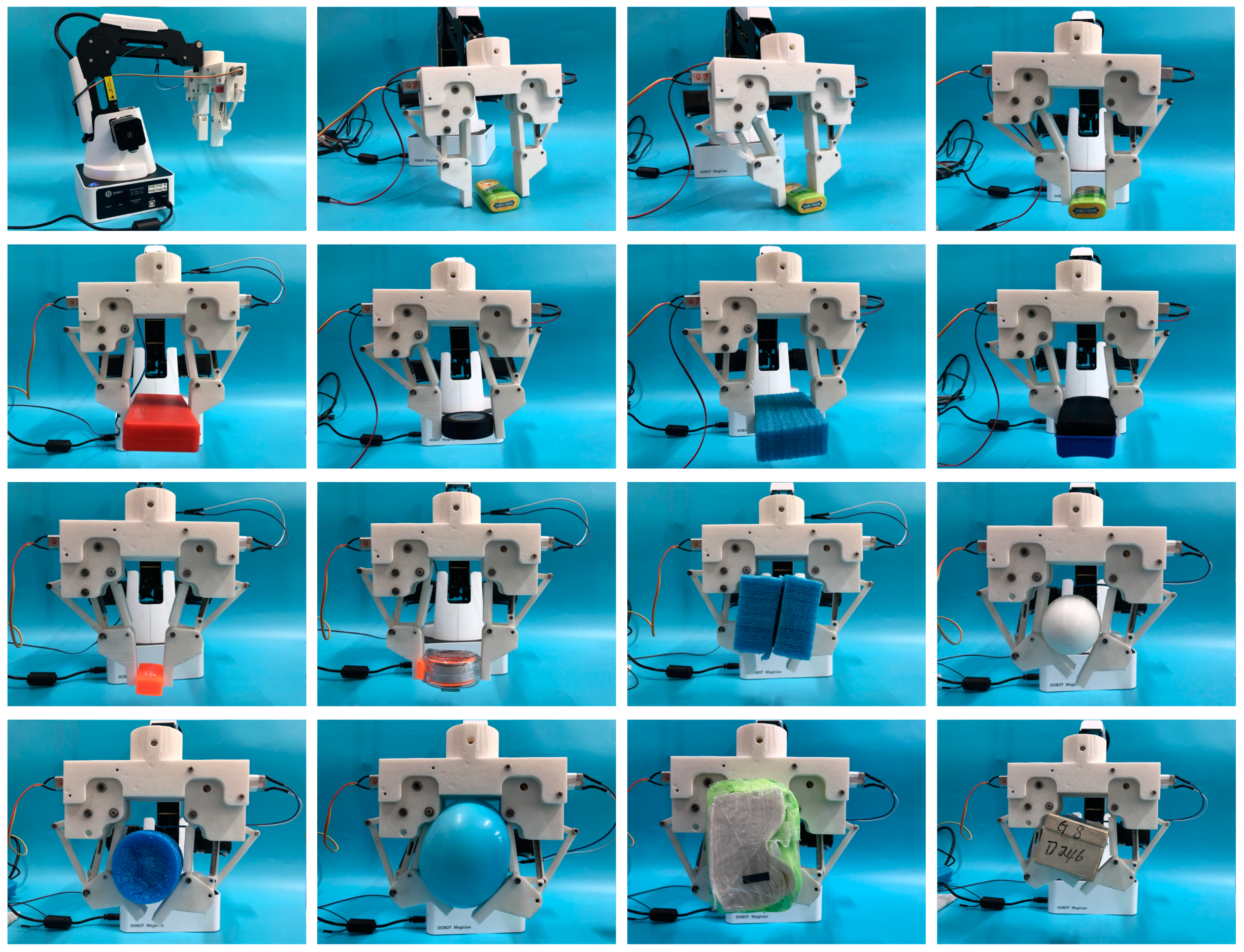
In practical experiments, both rigid and soft objects are used for grasping. In order to test the linear-parallel pinching function, no additional displacement from the robot arm was provided for the pinching process. In addition, for some pinching experiments, the two fingers have different rotational angles around the shaft, which can also help prove that the end of the finger moves along a straight line. The details of the experiments are shown in Figure 11.
As shown in Figure 11, the hand can perform hybrid grasping modes for different situations. It can grasp objects with different shapes and sizes and has a very good grasping ability to meet the requirements for industrial use, such as assembly or painting. Meanwhile, during the pinching process, the distal phalanx moves along a straight line as expected, which is suitable for grasping thin objects on a flat surface and overcomes the bottleneck of traditional hands. The prototype verifies the design and analysis to be reasonable. Some basic data and test results for the prototype are listed in Table 1.

6. Conclusions

This paper proposes a novel linear-parallel and self-adaptive hybrid grasping modes robot hand with a variable geometrical structure. Structure design, kinematics, dynamics are discussed and a prototype was manufactured to conduct grasping experiments. Kinematics analysis verifies the design of the straight-line mechanism and provides a universal guide for different application situations; the dynamics analysis reveal the forces, torques, and acceleration in all the linkages, which can provide some scientific reference for the design and manufacture process. Grasping experiments of the VGS hand were conducted to verify the analysis and the hybrid grasping modes of the hand, the experiments results indicate that the hand can perform hybrid-grasping modes by using the variable geometrical structure mechanism. In the pinching mode, the end of the finger moves along a straight line, which is suitable for grasping thin objects on a platform. In addition, the hand can adapt objects with different sizes, positions, and shapes. The hand has many potential applications.

Author Contributions

Conceptualization, C.L. and W.Z.; Methodology, C.L.; Validation, C.L.; Formal Analysis, C.L.; Investigation, W.Z.; Resources, W.Z.; Data Curation, C.L.; Writing—Original Draft Preparation, C.L.; Writing—Review and Editing, C.L. and W.Z.; Funding Acquisition, W.Z.

Funding

This research was supported by the National Natural Science Foundation of China (No. 51575302), Beijing Natural Science Foundation (No. J170005) and National Key R&D Plan of China (No. 2017YFE0113200).

Conflicts of Interest

The authors declare no conflict of interest.

References

  1. Liu, H.; Meusel, P.; Seitz, N.; Willberg, B.; Hirzinger, G.; Jin, M.H. The modular multisensory DLR-HIT-Hand. Mech. Mach. Theory 2007, 42, 612–625. [Google Scholar] [CrossRef]
  2. Engelberger, G. NASA’s Robonaut. Ind. Robot Int. J. 2013, 28, 35–42. [Google Scholar] [CrossRef]
  3. Jin, B.; Lin, L. Design and Force Control of an Underactuated Robotic Hand for Fruit and Vegetable Picking. J. Mech. Eng. 2014, 50, 1. [Google Scholar] [CrossRef]
  4. Van Der Niet, O.; Bongers, R.M.; Van Der Sluis, C.K. Functionality of i-LIMB and i-LIMB pulse hands: Case report. J. Rehab. Res. Dev. 2013, 50, 1123. [Google Scholar] [CrossRef] [PubMed]
  5. Kim, E.H.; Lee, S.W.; Lee, Y.K. A dexterous robot hand with a bio-mimetic mechanism. Int. J. Prec. Eng. Manuf. 2011, 12, 227–235. [Google Scholar] [CrossRef]
  6. Townsend, W. The BarrettHand grasper—Programmably flexible part handling and assembly. Ind. Robot Int. J. 2000, 27, 181–188. [Google Scholar] [CrossRef]
  7. Luo, C.; Zhang, W. A flexible self-adaptive underactuated hand with series passive joints. Ind. Robot Int. J. 2018, 44, 516–525. [Google Scholar] [CrossRef]
  8. Jacobson, S. The Utah/MIT dexterous hand: Work in progress. Int. J. Robot. Res. 1984, 3, 423–442. [Google Scholar]
  9. Lin, L.R.; Huang, H.P. NTU Hand: A New Design of Dexterous Hands. J. Mech. Des. 1998, 120, 282–292. [Google Scholar] [CrossRef]
  10. Zhou, J.; Yi, J.; Chen, X. BCL-13: A 13-DOF Soft Robotic Hand for Dexterous Grasping and In-Hand Manipulation. IEEE Robot. Autom. Lett. 2018, 3, 3379–3386. [Google Scholar] [CrossRef]
  11. Fukaya, N.; Toyama, S.; Asfour, T. Design of the TUAT/Karlsruhe humanoid hand. IEEE/RSJ Int. Conf. Intell. Robots Syst. 2000, 3, 1754–1759. [Google Scholar]
  12. Laliberté, T.; Birglen, L.; Gosselin, C. Underactuation in robotic grasping hands. J. Mach. Intell. Robot. Control Spec. 2002, 4, 77–87. [Google Scholar]
  13. Luo, C.; Yang, S.; Zhang, W.; Ren, Z.; Liang, J. MPJ Hand: A self-adaptive underactuated hand with flexible fingers of multiple passive joints. IEEE Int. Conf. Adv. Robot. Mech. 2016, 184–189. [Google Scholar] [CrossRef]
  14. Dollar, A.M.; Howe, R.D. The Highly Adaptive SDM Hand: Design and Performance Evaluation. Int. J. Robot. Res. 2010, 29, 585–597. [Google Scholar] [CrossRef]
  15. Liang, D.; Zhang, W. PASA-GB Hand: A Novel Parallel and Self-adaptive Robot Hand with Gear-belt Mechanisms. J. Intell. Robot. Syst. 2017, 90, 1–15. [Google Scholar] [CrossRef]
  16. Lamb, S.E.; Williamson, E.M.; Heine, P.J. Exercises to improve function of the rheumatoid hand (SARAH): A randomised controlled trial. Lancet 2015, 385, 421–429. [Google Scholar] [CrossRef]
  17. Qiao, S.L.; Liu, R.Q.; Guo, H.W.; Liu, Y.X.; Deng, Z.Q. Configuration Design of an Under-Actuated Robotic Hand Based on Maximum Grasping Space. Chin. J. Mech. Eng. 2018, 31, 35. [Google Scholar] [CrossRef]
  18. Ma, R.; Odhner, L.U.; Dollar, A.M. A modular, open-source 3D printed underactuated hand. In Proceedings of the IEEE International Conference on Robotics & Automation (ICRA), Karlsruhe, Germany, 6–10 May 2013. [Google Scholar]
  19. Hussain, I.; Salvietti, G.; Malvezzi, M. On the Role of Stiffness Design for Fingertip Trajectories of Underactuated Modular Soft Hands. In Proceedings of the IEEE International Conference on Robotics and Automation ICRA, Singapore, 29 May–3 June 2017. [Google Scholar]
  20. Luo, C.; Zhang, W. Development of a Novel Linear-Parallel Robot Hand. International Conference on Intelligent Robotics and Applications; Springer: Cham, Switzerland, 2018. [Google Scholar]
  21. Luo, C.; Zhang, W. Robot Finger Device of Connecting Rod Gear Sliding Groove with Linear Parallel Grabbing Function. CN108972602-A, 7 June 2017. [Google Scholar]
  22. Zhao, J.; Feng, Z.; Chu, F.; Ma, N. Advanced Theory of Constraint and Motion Analysis for Robot Mechanisms; Academic Press: Cambridge, MA, USA, 2014; pp. 113–157. [Google Scholar]
Figure 1. Linear-parallel pinching and self-adaptive grasping modes.
Applsci 09 01566 g001
Figure 2. The working principle of the finger mechanism.
Applsci 09 01566 g002
Figure 3. The length of the elastic component under different situations.
Applsci 09 01566 g003
Figure 4. The architecture of the proposed VGS finger.
Applsci 09 01566 g004
Figure 5. Kinematic model of the VGS finger mechanism.
Applsci 09 01566 g005
Figure 6. Kinematic details of the distal phalanx.
Applsci 09 01566 g006
Figure 7. Equitant dynamics model of the finger mechanism.
Applsci 09 01566 g007
Figure 8. Contact force diagram of the finger mechanism.
Applsci 09 01566 g008
Figure 9. The relationship of contact force and parameters under pinching mode, where T = 1 Nm, F1 = 0, β2 = constant, θ3 = θ2.
Applsci 09 01566 g009
Figure 10. The prototype of the VGS hand.
Applsci 09 01566 g010
Figure 11. Grasping experiments of the VGS hand.
Applsci 09 01566 g011
Table 1. Basic parameters and test results.
ParameterValueUnit
The weight of the robot hand483g
Dimensions of the robot hand162 × 49 × 128mm
Degree of freedom 41
Number of motors21
Working voltage12V
Action time for linear-parallel pinching 2.3s
Action time for self-adaptive grasping3.6s
Minimum grasping thickness (linear-parallel pinching mode)2.0mm
Maximum grasping weight under linear-parallel pinching mode3.8kg
Maximum grasping weight under self-adaptive grasping mode5.2kg
Grasping range (diameter size)0.1–30cm

