Article

Influence of Burner Nozzle Parameters Analysis on the Aluminium Melting Process

Technical University of Kosice, Faculty of Materials, Metallurgy and Recycling, Institute of Metallurgy, Letná 9, 042 00 Košice, Slovakia
*
Author to whom correspondence should be addressed.
Appl. Sci. 2019, 9(8), 1614; https://doi.org/10.3390/app9081614
Submission received: 12 March 2019 / Revised: 1 April 2019 / Accepted: 14 April 2019 / Published: 18 April 2019
(This article belongs to the Section Energy Science and Technology)

Abstract

:
The paper presents the results of the optimisation of burner nozzle diameters during the combustion of natural gas under the conditions of increasing oxygen concentrations in the oxidizer in aluminium melting processes in drum rotary furnaces. The optimisation of outlet nozzle diameters was performed employing the method of experimental measurements, the results of which can be used for aluminium melting in hearth furnaces. The measurements were carried out using an experimental upstream burner with 13.5 kW input power. The monitored oxygen concentrations in the oxidizer ranged from 21% to 50%. The measurements were performed and evaluated in two variations of the burner configuration (geometry). In the first study, the impact of the enriched oxidizer on the melting of aluminium ingots was evaluated with the defined diameter of the air nozzle, which resulted in a reduction of the aluminium charge melting time by 50% at 45.16% oxygen concentration in the oxidizer, thus achieving savings in the consumption of fuel used for melting. In the second study, the diameter was optimised depending on the combustion rate of the natural gas and oxidizer mixture. The optimisation of the nozzle parameters resulted in the reduction of the charge melting time by 23.66%, while the same 25% enriched oxidizer was used. With the rise of the enrichment level to 35%, further reduction by approximately 12% was observed. The measurement results prove considerable influence of the parameter (geometry) optimisation of the outlet nozzles and oxidizer enrichment. Appropriately selected parameters of the burner can contribute to achieving comparable results at a lower enrichment of the oxidizer. The obtained results demonstrate the intensification of the heat transfer in the current thermal aggregates. The research conclusions confirm that oxygen-enhanced combustion and modification of existing burners reduces the specific energy consumption on the process and reduces CO2 emissions.

1. Introduction

Primary aluminium production from bauxite ore is an energy-intensive process. Currently, ever-greater emphasis is placed on secondary aluminium production. According to the OECD, secondary aluminium production will amount up to 37% of the total quantity of aluminium produced in 2020 [1]. Currently, the dominant method of secondary aluminium production is the recycling of scrap high in aluminium and its subsequent remelting in smelting furnaces. Compared with primary aluminium production from raw materials, aluminium recycling allows a reduction of 95% of the required energy per ton of aluminium [2].
At present, a large variety of furnaces, differing from each other in the method of processing the charge, are used for secondary aluminium melting. Rotary furnaces are the most common type of thermal aggregates used for secondary aluminium production [3]. Based on their design, rotary furnaces can be divided into drum rotary furnaces and tilting rotary furnaces, which are described in more detail in [4,5,6]. Global energy and environment policies push manufacturers towards increasing the thermal efficiency of thermal equipment while reducing emissions from technological processes.
The current trend in the operation of these types of thermal aggregates is air-fuel combustion, in which fuel is combusted with oxygen-enriched air or oxy-fuel combustion. The authors of those publications agree that an important factor in aluminium melting processes characterised by increased oxygen concentrations is represented by the increase of combustion temperatures in the furnace work area (see [7,8,9,10,11,12,13]).
From the viewpoint of using oxygen during the aluminium melting process, an optimum level of oxygen enrichment for the oxidizer must be determined. This issue is well addressed by Saha [10] and Jepson [9].
In his study related to the use of oxygen, Saha [10] presented an optimized type of the burner known under the commercial name RAPIDFIRETM, manufactured by Air products. This burner type is a combination of an oxy-fuel burner and an air-fuel burner. This construction variant provided a high flexibility in firing gas and was specially designed for aluminium smelters. According to the results of this study, the replacement of the air-fuel burner with the RAPIDFIRE burner resulted in the increase of the furnace productivity by 31% and fuel savings reached 36% at 80% oxygen enrichment of the combustion air.
In their study, Jepson et al. [9] used Air Liquide Pyre Tron burner and they monitored the melt rate of the charge using O2 enriched combustion air, with the O2 volume between 25% and 75%. At this level of enrichment, the melt rate increased within the range of 25% to 50%. According to Jepson, factors that influence the optimum level of oxygen enriched combustion air include the following: Type of furnace, type of the charge, number and location of burners, and the cost of fuel and oxygen.
In their study, Jablonsky et al. [6] addressed the influence of the increased oxidizer oxygen on the combustion process and heat transfer. At the same time, they monitored its influence on the temperature field distribution in the thermal aggregate. In their study, these authors pointed to the fact that no significant changes of the temperature field distribution occur at larger distances from the burner, when the oxidizer oxygen concentration increases and the burner input power remains constant. This can be explained by the findings presented by Baukal [14,15,16], which state that the increase in combustion temperature caused by the increase in oxygen concentrations in the oxidizer influences mainly the fuel combustion kinetics. The increase in the oxidizer oxygen concentration results in a lower activation energy needed for chemical reactions in the combustion process. Higher oxygen concentrations contribute to the decrease in the amount of the burnt mixture and its flammability at lower temperatures. Ultimately, the combustion rate using pure oxygen is 11 times higher compared to air. Subsequently, when the enrichment technology is used with a burner designed for air fuel combustion, either the flame front is reduced or backflash into the burner may occur.
At present, there is only little available literature which deals with the impact of the flame front shortening on the charge heating. The shortening of the flame in the thermal aggregate results in changes in the temperature field distribution due to changes in flowing flue gas turbulence (rate distribution). Consequently, the charge heating process is significantly affected. Therefore, when evaluating the overall effect of oxygen in thermal aggregates, attention should be paid to this particular issue.
A solution to the above issue lies in modifying combustion mixture flow rates from the burner. Modifications to the burner nozzle diameters can cause changes in the flame length in the thermal aggregates and, thus, contribute to achieving greater efficiency of using oxygen in the thermal aggregates and to the increase of technological process efficiency.
The authors of this article designed and created an experimental burner, featuring the possibility to modify outlet nozzle diameters, and an experimental model of the tilting rotary furnace to investigate the impact of oxygen enrichment on combustion air and the effect of discharge rates on the heating rate and melting of aluminium. The computional fluid dynamiscs (CFD) model of the experimental device was used to design and modify the burner. In the present article we also present a solution to the issue of heat transfer intensification by modifying the burner on the basis of the combustion mixture flow rate change.

2. Experimental Research

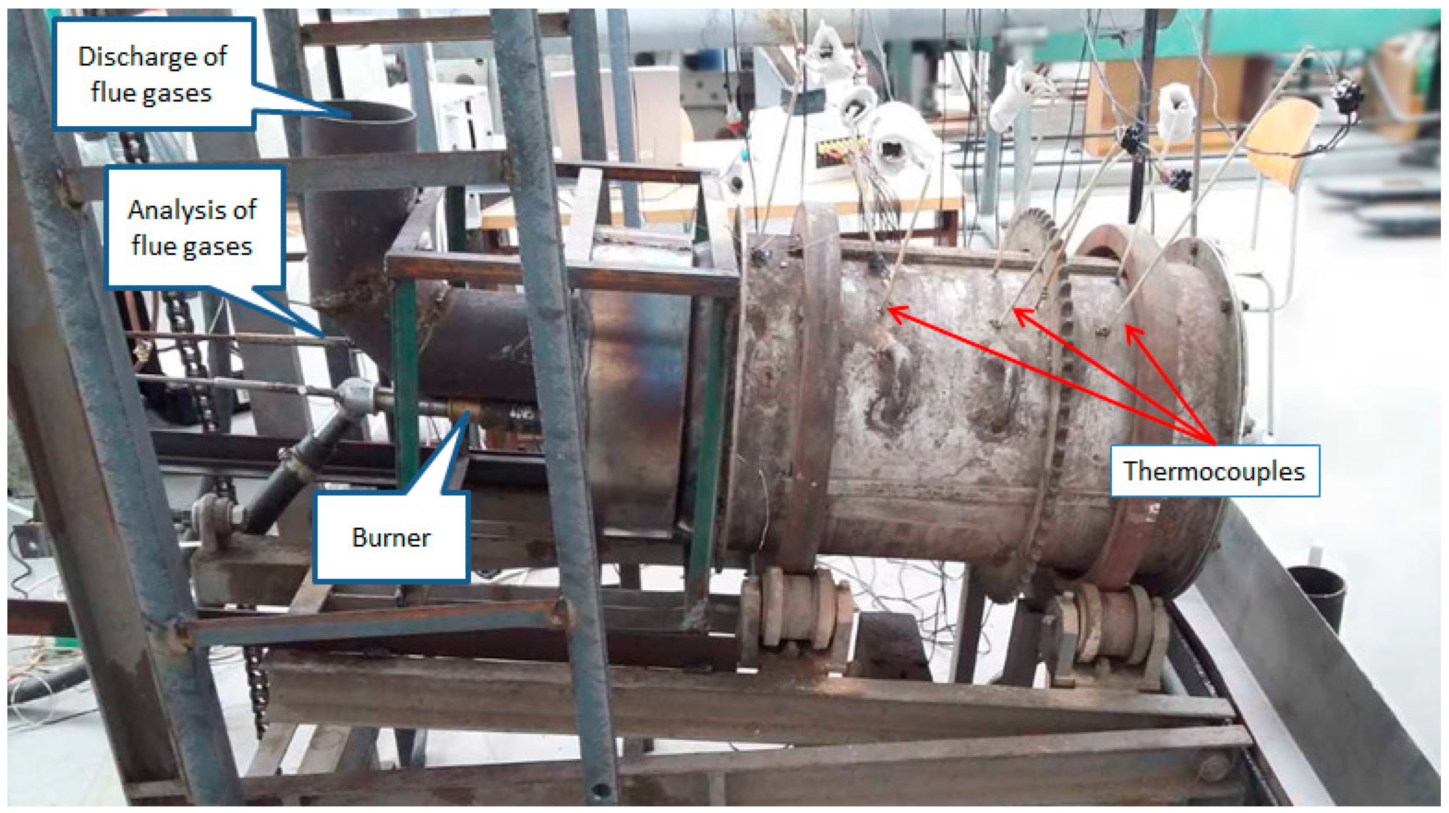
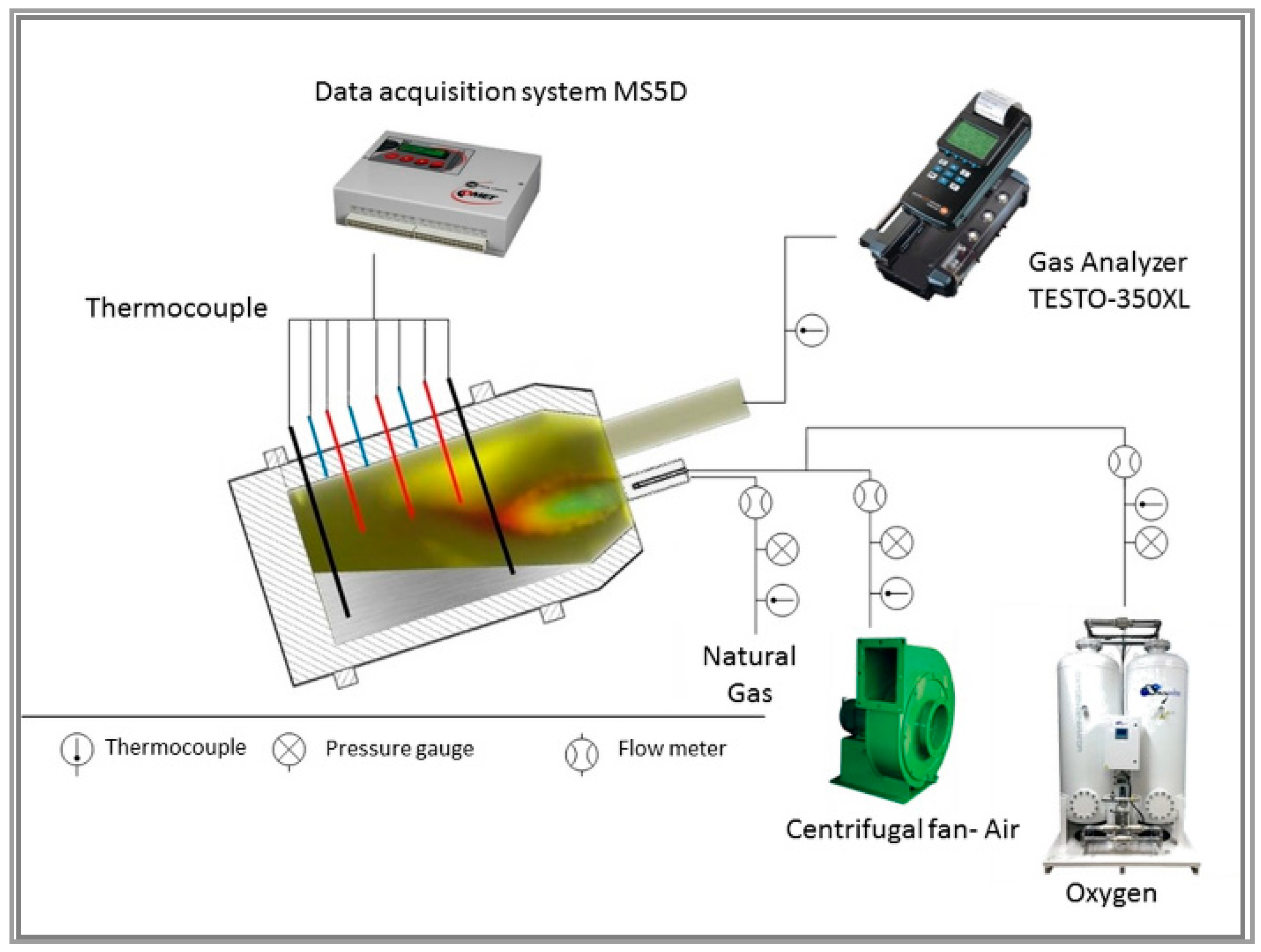
2.1. Experimental Device

The aim of the research was to analyse heat transfer and aluminium melting processes in the experimental device, in relation to the change of the combustion mixture flow rate from the burner. The experimental measurements were carried out with the oxidizer oxygen concentration ranging from 21% to 50%. The experiments were conducted using a tilting rotary furnace (Figure 1) with an inner diameter of 305 mm and a length of 607 mm. The experimental model inclination angle was set to 7° during the measurement.
The furnace was equipped with a 16 K (NiCr-NiAl) PTTK-TKb-60-2-SP thermocouples (MERATEX, s.r.o., Košice, Slovakia), for which the manufacturer states a measurement uncertainty at the level of ±2.5 °C within the temperature range up to 1200 °C. The thermocouples were used to continually sense the temperature distribution changes in the combustion area, lining, stack, and charge. As the thermocouples were placed on the casing, the experimental model did not rotate during the experiment. The flue gas composition was analysed by a TESTO 350XL flue gas analyser (K-TEST, s.r.o., Košice, Slovakia). Other parameters relevant for the furnace operation were recorded by the furnace control system (Figure 2).
The charge was composed of aluminium ingots with the size of 5 × 10 × 2.5 cm. The total charge weight was 15 kg. To guarantee comparability of individual measurements, the process of experimental measurement was terminated when the charge reached the temperature of 740 °C.

2.2. Modification of Burner

The experimental measurements were carried out using a burner with 13.5 kW input power for the natural gas combustion. Due to the shortening of the flame front at higher concentrations of oxygen in the oxidation mixture, the outlet diameter of the burner was modified during the experimental research, according to oxygen concentrations in the oxidizer at the constant fuel flow. The burner orifice was modified (according to the Equation (1)), so that the flame length was the same for each examined level of oxygen enrichment from the oxidizer [6,17]:
L f l = r ( w m u n ) 2 1 ,
where Lfl is the flame length (m), r is the semi-diameter of the burner orifice (m), wm is the outlet rate of the mixture (m s−1), and un is the normal combustion rate of the oxidizer and gas mixture (m s−1).
On the basis of Equation (1), the flame length in the air fuel combustion was set to 42 cm. The increase of oxygen concentration results in the reduction of the combustion mixture amount, and hence, the outlet rate of the mixture wm decreases. As already noted, the increase of the oxygen concentration in the combustion mixture results in the increase of the combustion rate un. On the basis of available literature data [16], the parameter un for natural gas with the increased oxidizer oxygen concentration can be expressed using the following mathematical function:
u n = 8.4 × 10 7 O 2 3 1.0898 × 10 4 O 2 2 + 0.06228767 O 2 0.94666177 ,
where O2 is the oxidizer oxygen concentration (vol. %)
Thus, the flame length is simultaneously reduced by both parameters wm and un. Therefore, in order to achieve a constant flame length, it is necessary to modify the diameter of the burner orifice.
For the purpose of studying the impact of the increased oxygen concentration in the air on the combustion process, an upstream burner was selected. The burner consists of a closed gas tube with a diameter of 8 mm, with four holes with diameters of 2.5 mm (Figure 3a) transversally drilled along the perimeter to ensure a better mixing of fuel and oxidizer. Construction modifications of the burner consisted of producing an optimised air nozzle for each examined level of oxygen enrichment of the oxidizer. The increase of the oxygen concentration was ensured by injecting oxygen into the combustion air inlet.

2.3. CFD Modeling

Numerical simulation of the combustion process was computed in ANSYS CFX v 17.2. ANSYS CFX computes discrete values of time-dependent Navier–Stokes equations, which are conservation equations of momentum in x-, y-, and z-directions, and the conservation equation of mass. Time-dependent details of turbulent eddies are removed from the Navier–Stokes equations with Reynolds averaging and the effect of turbulent motion on transport of momentum in the averaged flow is assumed by means of the Boussinesq hypothesis, which defines turbulent viscosity. Turbulent viscosity increases the basic molecular viscosity of the fluid. Computation of turbulent viscosity requires additional equations, which are based on the k-epsilon RNG model. The combustion process was defined using a combination of finite rate chemistry and eddy dissipation models. The basis for the calculation of combustion was the global reaction scheme of methane combustion, methane air water-gas shift (WGS) [18], defined by the following relationships [16,18,19]:
C H 4 + 0.5 O 2 C O + 2 H 2 O ,
H 2 + 0.5 O 2 H 2 O ,
C O + 0.5 O 2 C O 2 ,
C O + H 2 O C O 2 + H 2 .
The Equations (3) to (6) were defined for the combustion of methane and air. However, the flame temperature and the course of chemical reactions at oxy-combustion and air-combustion differ. The higher combustion temperatures lead to a greater dissociation of the flue gas components. Therefore, these changes have to be incorporated into the mathematical model. The course of chemical reactions in the mathematical model can be influenced by the change of mathematical dependences of the chemical reaction on temperature, which is expressed by the Arrhenius equation (7). In their work, Andersen [19], Bibrzycki [20], and Levenspiel [21] optimised kinetic parameters of the chemical reactions in order to make them suitable for mathematical modelling of oxy-combustion (8–11).
k = A . e E a R T ,
where k is the rate constant, Ea is the activation energy (J mol−1), R is the universal gas constant 8.314 J K−1 mol−1, and T is the absolute temperature (K).
The optimized rate constant for the Equations (3) to (6) is given as follows [19,20,21]:
k 1 = 1.59 10 13 . e 47800 R T [ C H 4 ] 0.7 [ O 2 ] 0.8 ,
k 2 = 5.0 10 20 . e 30000 R T [ H 2 ] 0.25 [ O 2 ] 1.5 ,
k 3 = 3.98 10 8 . e 10000 R T [ C O ] [ O 2 ] 0.25 [ H 2 O ] 0.5 ,
k 4 = 2.75 10 12 . e 20000 R T [ C O ] [ H 2 O ] .
Boundary conditions for the gas and oxidizer inlet were defined by the mass flow, pursuant to Table 1. The radiation heat transfer was modelled using the P1 model based on the expansion of the radiation intensity into an orthogonal series of spherical harmonics.
The DesignModeler software was used to create a model of a furnace with the incorporated combustion chamber of the physical model and the charge. The mathematical model of the physical module was discretized for the computing network. The combustion chamber was created using tetrahedral mesh and it was concentrated more in the area of the walls and burner, where larger gradients were assumed due to the hexahedral layer, which ensured the correctness of the velocity field creation. The mesh adjacent to the walls in the region of the boundary layer has perpendicular geometric spacing, with a multiple of 1.15 between the heights of consecutive layers of volumes, and the first layer of volume has a height of 0.035 mm. The worst value of y+ was 15 and it was observed in the stack area. In other areas, it ranged from 0 to 1.5. The charge was created using a hexahedral mesh with a side length of 10 mm, with the aim of ensuring the correct calculations of the thermal gradients on the charge and to minimizing the influence of the mesh on the results. The total computational mesh is composed of almost a million cells.
Required volumes of air and oxygen had to be defined for each experimental measurement in order to achieve the required oxygen enrichment level of the oxidizer. Table 1 shows the volume flows of the inlet media in relation to the examined oxygen concentrations in the oxidizer and suggests optimised diameters of the air nozzles, D1, in accordance with Equation (1).
The mixing of the gaseous fuel stream with the oxidizer is shown using the CFD simulation in Figure 3b. The simulation of the gaseous media flow shows the gaseous fuel stream passing from the gas nozzle into the oxidizer. The oxidizer oxygen concentration was checked using the stoichiometry of natural gas combustion. Table 2 shows the natural gas composition.

2.4. Heat Balance of Process

The impact of air nozzle optimisation on the process of aluminium ingot melting needs to be determined from the heat balance results. As already mentioned above, a critical parameter in the analysis of the impact of the increased oxidizer oxygen concentration is the time the charge needs to reach the temperature of 740 °C. The melting time, τ, is primarily affected by the change of the overall heat transfer coefficient, αo, to the charge in the work area.
The total time required for the entire technological process is as follows:
τ = Q U H α o ( t f ¯ t b ¯ ) S ,
Q U H = Q U H 1 + Q U H 2 + Q U H 3 .
QUH1 is the heat required for heating the material to the melting temperature, as follows:
Q U H 1 = m A l ( c t , A l 2 t 2 c t , A l 1 t 1 ) .
QUH2 is the heat required for melting the material, as follows:
Q U H 2 = m A l l A l .
QUH3 is the heat required for heating the melt to the casting temperature, as follows:
Q U H 3 = m A l ( c t , A l 3 t 3 c t , A l 3 t 3 ) ,
where mAl is the mass of aluminium ingots (kg), ctAl1 is the specific heat capacity of aluminium at ambient temperature (J.kg−1 K−1), ctAl2 is the specific heat capacity of aluminium at melting temperature (J.kg−1 K−1), ctAl3 is the specific heat capacity of aluminium at the temperature of 740 °C (J.kg−1 K−1), t1 is the temperature of the aluminium charge (°C), t2 is the melting temperature of the aluminium charge (°C), t3 is the final temperature of the aluminium charge (740 °C) (°C), lAl is the latent heat (J.kg−1), t f ¯ is the average temperature in furnace (°C), and t b ¯ is the average temperature of the charge (°C).
The evaluation of heat flow changes on the charge was performed by measuring the temperature field in the combustion chamber by the thermocouples. The overall heat transfer coefficient, αo, in the furnace work area is characterized by the following equation [6]:
α o = α c + α r ,
where αc is the heat transfer coefficient by convection (W m−2 K−1) and αr is the heat transfer coefficient by radiation (W m−2 K−1).
The value αr is affected mainly by the fourth power of the thermodynamic temperature and by the flue gas emissivity, which depends on the flue gas composition. When increasing the oxidizer oxygen concentration, the concentrations of CO2 and H2O in flue gas rise. These components have a significant effect on the increase of the flue gas emissivity. The results of mathematical calculations for the theoretical temperature, temperature with dissociation, and flue gas emissivity (Figure 4) illustrate that a proportion of the radiation component, αr, increases with the increase of the oxidizer oxygen concentration (the increase in flue gas temperature and emissivity). The value αc is influenced by the amount and flow rate of flue gas in the work area. The increase of the oxidizer oxygen concentration results in the reduction of the flue gas amount. The rate and distribution of the flue gas flow in the work area and the way flue gas flows around the charge can be influenced by the burner geometry.
At the constant diameter of the burner orifice, the proportion of the convection component, αc, in the heat transfer process in the work area is reduced (the influence of the flue gas speed and the flame length vs. flue gas temperature) due to the reduction of the flue gas quantity. The optimisation of the burner orifice results in the change of the flue gas flow in the furnace work area, which causes the increase of the proportion of the convection component αc in the heat transfer, compared with the ordinary orifice. The flue gas composition is not changed when the optimized burner orifice is used. A possible temperature increase in the work area caused by the flame lengthening can result in a slight increase in the proportion of the radiation component, αr, compared to the ordinary air nozzle. The use of the optimized air nozzle results in an increase of the overall heat transfer coefficient, αo, in the work area to the charge, compared to the ordinary air nozzle.
The overall heat transfer coefficient in the work area is based on the balance of individual components of the heat intake and removal (for more details, see [6]).
The mathematical model for calculating the useful heat of the charge is based on the kinetics of the heating and melting processes in the examined thermal aggregate and on the knowledge of the heat transfer between flue gases and charge in the furnace, based on the heat transfer by convection and radiation. The calculation is divided into separate time intervals, Δτ, defined on the basis of the flue gas temperature course, sensed by means of the thermocouples in the combustion chamber.
The quantity of useful heat, ΔQUH, transferred to the charge can be also expressed as the sum of heat transferred by radiation and convection from flue gas and heat from the lining ΔQl, [6] as follows:
Δ Q U H = Q r + Q c + Δ Q l = α o ( T f g T b ) S Δ τ + Δ Q l .
The heat quantity transferred from the lining, ΔQl, to the process depends on the furnace type. The effect of heat is most prominent during the rotary motion of the furnace, when its lining is in direct contact with flue gases and the charge. In a stationary furnace, the heat is transferred from the lining to the charge only through radiation. The heat quantity, Qc, transferred to the charge surface during the heat transfer process by convection is described as follows [6]:
Q c = α c ( T f g T b ) S Δ τ ,
where αo is the total coefficient of the heat transfer from the furnace work area to the charge (W m−2 K−1); αc is the convection heat transfer coefficient (W m−2 K−1); S is the heat transfer surface area (m2); Tfg is the flue gas temperature (K); and Tb is the charge temperature (K); ∆τ calculation time step (s).
The convection heat transfer in a closed body system (charge, lining, flue gases) is best expressed by the following relationship [6]:
Q r = c [ ( T f g 100 ) 4 ( T b 100 ) 4 ] S Δ τ = α r ( T f g T b ) S Δ τ ,
where c is the total coefficient of the mutual heat transfer by radiation (W m−2 K−4), for more details, see [6].
The total useful heat of the process is given by the following equation:
Q U H = Δ Q U H .
The total time of the melting process is given by the following equation:
τ = Δ τ .

3. Results and Discussion

3.1. Results of CFD Modeling

The influence of the air nozzle diameter on the combustion process in the physical model of the rotary furnace can be determined on the basis of the mathematical modelling results. Mathematical modelling enables investigation of the flame shape, flue gas flow, temperature field distribution, heat flow to the charge, and the distribution of concentrations of individual components under the stabilised conditions. The results of the mathematical modelling confirmed the hypothesis that the increase of oxygen concentrations in the oxidizer causes the shortening of the flame. Figure 5 (on the left) illustrates the temperature fields at the ordinary air nozzle diameter and oxygen concentrations in the oxidizer within a range of 21% to 50%. On this basis, the flame shape and the temperature distribution in the combustion chamber related to the changes of oxygen concentrations in the oxidizer can be determined. The results of the CFD simulations suggest that, for this particular type of a burner with the conventional air nozzle, the oxygen enrichment of the oxidizer cannot exceed 50% during the combustion process. When the oxidizer oxygen concentration is higher, backflash into the burner or possible thermal damage to the burner orifice can occur.
On the basis of the mixture combustion rate, a constant flame length can be maintained by optimizing the burner air nozzle diameter. The results of the mathematical modelling, shown in Figure 5 (on the right), confirmed the possibility of optimizing the air nozzle diameter when the oxidizer is enriched, in accordance with the Equation (1).

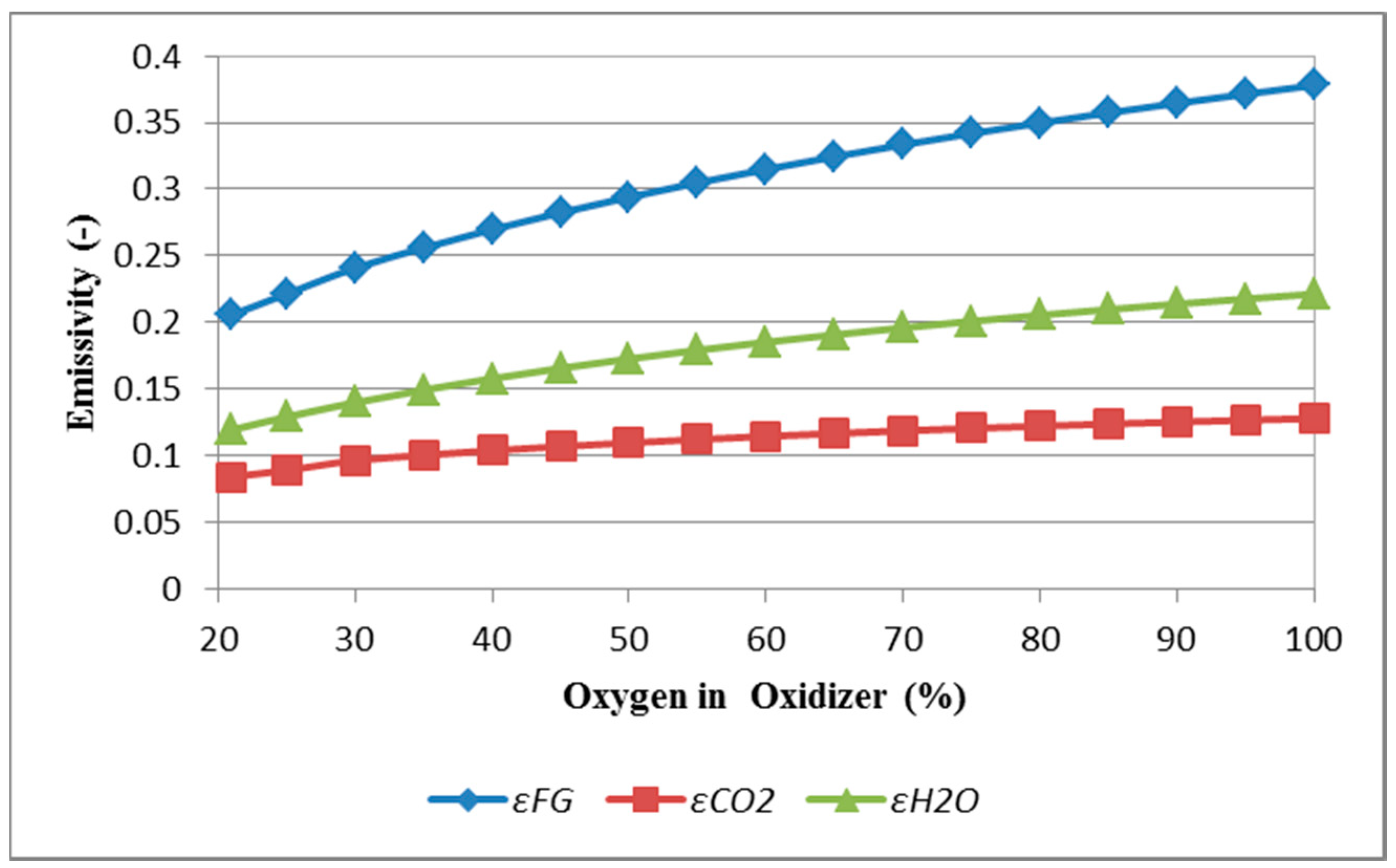
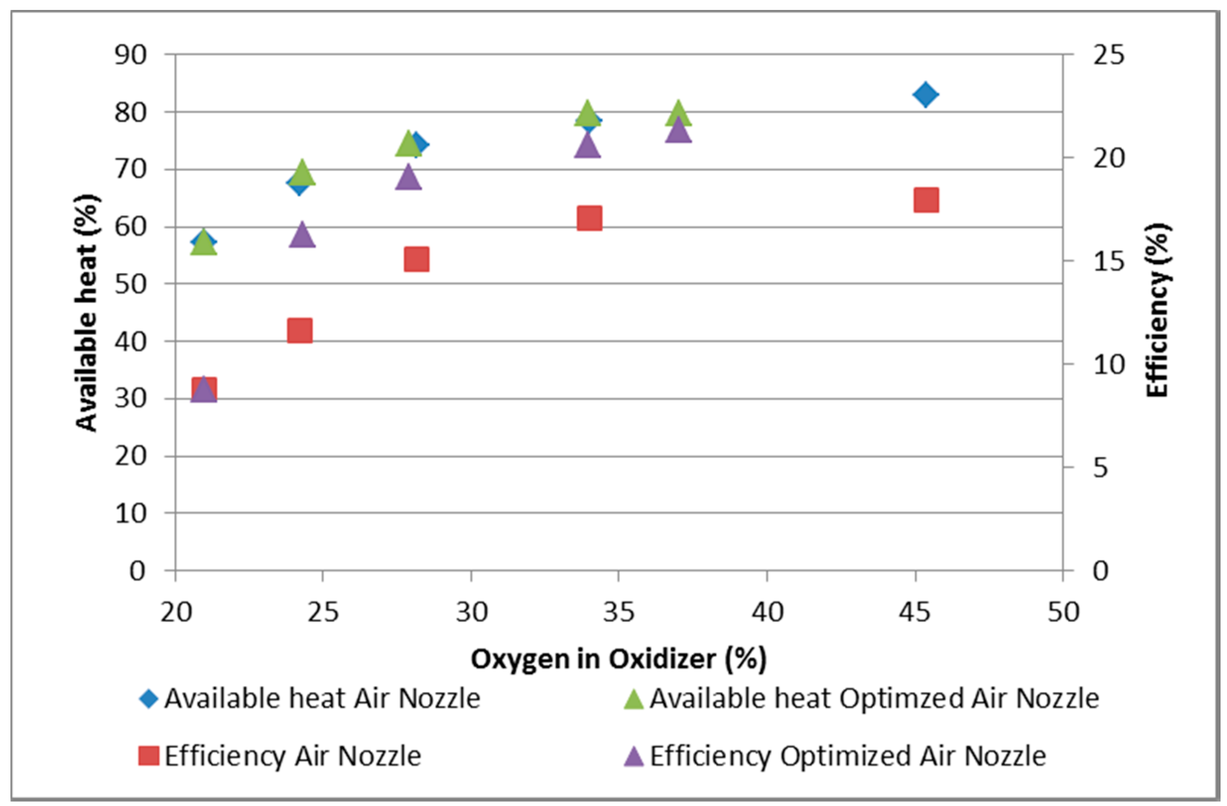
3.2. Results of Experimental Measurements

The correctness of the chosen methodology (measurements using the experimental device) can be confirmed by comparing the achieved results with those obtained by a group of American scientists. Jepson and Kampen [9] studied the influence of oxygen concentrations in the oxidizer on the furnace productivity and operating costs for 10 ton rotary melting furnaces. Power consumption for heating, melting, and overheating 1 kg of the charge was used as a main criterion for the evaluation of the benefits of the optimisation of burning natural gas in the process of oxygen enrichment from the oxidizer. Figure 6 shows the results of the experimental measurements. The blue line illustrates the results obtained by Jepson and Kampen. The red line illustrates the results obtained by experimental measurements using the ordinary air nozzle. The green line illustrates the results obtained by experimental measurements using the optimized air nozzle.
The impact of the enriched oxidizer on the process of aluminium melting in the experimental device is comparable with the experimental results obtained by Jepson and Kampen [9]. At oxygen concentrations above 30%, no significant reduction occurs in the specific fuel consumption required for heating and melting the charge. The difference in the specific heat energy consumption needed for melting the charge results from higher heat losses of the experimental device, the differences in the amount of charge, and the output and size of thermal aggregates. Complete verification requires the inclusion of these factors into calculations of the results obtained from the experimental device. Based on the experimental measurement results, it is obvious that the use of optimized air nozzles can result in the reduction of the fuel consumption for charge heating and melting by 21%, while the oxidizer oxygen concentration remains at the same level, approximately 30%.
As already noted, the efficiency of this device depends on the amount of available heat released in the thermal aggregate. The amount of available heat is influenced by the heat loss from exhaust flue gases, which is calculated on the basis of the measured temperature of the exhaust flue gases. The temperature of the exhaust flue gases in the experimental device chamber was about 700 °C. Based on the calculations, the amount of available heat in the experimental device reached as much as 82% of the supplied heat at 45% enrichment of the oxidizer.
Figure 7 illustrates the influence of the oxygen concentration on the energy efficiency of the experimental device. The value of the energy efficiency of the experimental device rises with the increased oxygen concentrations in the oxidizer. As a result of the optimisation of the air nozzle, the heat transfer from the flame is directed to the charge, thus increasing the efficiency of the experimental device. At 30% oxygen concentration in the oxidizer, the energy efficiency increased by 4% due to the air nozzle diameter optimisation. As illustrated in Figure 7, the amount of available heat is not influenced by the air nozzle diameter changes.
Based on the dependencies shown in Figure 7, the course of heating the charge in the experimental device due to the increased oxygen concentration cannot be determined. Figure 8 graphically illustrates the changes of the mean temperature of the charge during the experimental measurement using the ordinary (not optimized) air nozzle. Aluminium melting is defined as a phase transformation from the solid state to the liquid one. Crystalline substances, including aluminium, are melted at a constant temperature; however, at the same time, a slight overheating of the melt being formed occurs, which also suggests a slight increase in the temperature within the melting interval in the graph (Figure 8 and Figure 9). In this stage, the material absorbs the heat required for the change of its physical state (latent heat). The value of latent heat for the aluminium fusion is approximately 398 kJ kg−1. The melting phase is terminated when the charge temperature starts rising slightly again. The final phase of the aluminium overheating is necessary to avoid possible aluminium solidification in the tapping hole during tapping. On the basis of the charge heating rate analysis, it can be determined how the heat flow changes with the increase of oxygen concentrations in the experimental device.
The course of charge temperatures, shown in Figure 8, used for aluminium heating, melting, and overheating, with increasing oxygen concentrations in the oxidizer, proves the reduction of the overall time. A significant reduction of melting time is reported at the oxidizer oxygen concentration of up to 35%. At the oxygen concentration of 34.36%, used in the experimental measurement, the 46.29% reduction in melting time was achieved, compared with the melting time in air fuel combustion. No significant reduction of melting time occurred when the oxygen concentration increased to 46.15%.
When using the optimized air nozzle diameter (Figure 9), the melting time is reduced significantly with 25% oxygen concentration, where the optimisation contributed to the 45.47% reduction of the melting time, compared with air combustion. When comparing the obtained results with those obtained when using the ordinary nozzle, it can be concluded that, when the optimized nozzle is used with a 24.32% oxygen concentration, the melting time can be reduced by the same percentage, as in the case of a 34.36% oxygen concentration using the ordinary nozzle. The same trend can be observed at higher oxygen concentrations in the oxidizer when the melting time can be reduced by as much as 58.23% under the conditions of 37.02% oxygen enrichment, using the optimized nozzle.
Thus, the main advantage of the nozzle optimisation lies in the decrease of oxygen consumption and the related operational costs, while maintaining or even slightly increasing the productivity of the experimental device. However, the influence of optimisation is also related to the decrease of the amount of produced flue gases at higher oxygen concentrations.
Figure 10 and Figure 11 show the calculated increase in the specific heat of the metalliferous charge heating and melting, resulting from Equations (12)–(22). The figures show the course of the charge heating, melting, and overheating phases for relevant cases of oxygen enrichment from the oxidizer. The curves illustrate the completion of the metalliferous charge melting and the impact of oxygen enrichment from the oxidizer on the reduction of the melting process.
Figure 12 presents the calculated resulting values of the mean overall heat transfer coefficient in the work area to the charge when the ordinary air nozzle is used. These results correspond to the results of study [5], conducted at the Gas Technology Institute. The increase of the oxygen concentration has a significant impact on the increase of the overall heat transfer coefficient, up to 35% of the oxygen concentration in the oxidizer. No significant increase of the overall heat transfer coefficient on the charge in the work area occurs with further increase of the oxygen concentration. The optimisation of the air nozzle diameter contributed to the increase of the proportion of the heat transfer by convection, which influenced the increase of the overall heat transfer coefficient in the furnace work area, as shown in Figure 12.
The experimental measurement results confirmed that the optimum level of the oxidizer enrichment in the rotary furnaces is 35%. This is also supported by the results of the mathematical modelling of the natural gas combustion with the enriched oxidizer, as shown in Figure 13. The increase of the theoretical combustion temperature of natural gas with the enriched oxidizer is strongly influenced by the CO2 and H2O dissociation. At 35% enrichment from the oxidizer, the combustion temperature with dissociation increases to 2400 °C, which represents about 50% of the overall combustion temperature increase. The increase of the oxidizer oxygen concentration above 35% results in slowing the rate of the temperature increase in the thermal aggregate, as the significant part of the thermal energy is used for endothermic reactions. Another factor influencing the melting of aluminium is the flue gas volume. Figure 13 shows the drop of flue gases at a 36.33% oxygen concentration and up to 72% at 100% oxygen concentration when the oxidizer oxygen concentration increases to 35%. A characteristic feature of this type of thermal aggregate consists of locating the burner on the same side as the flue gas outlet. This constructional arrangement is not very suitable at high concentrations of oxygen in the oxidizer because the reduction of the flue gas quantity results in a faster removal of flue gases from the furnace area. Thus, when using the ordinary air nozzle, a significant reduction of overall heat transfer occurs in the furnace area due to a low discharge rate. The optimisation of the air nozzle contributes to the extension of the residence time of flue gas in the furnace area, which results in the increase of the heat transfer from the flue gas to the charge.

4. Conclusions

Based on the results from the laboratory experimental device of the tilting rotary furnace for the melting of aluminium materials, it can be stated that a suitable optimisation of the air nozzle at increased oxygen concentrations in the oxidizer leads to the following:
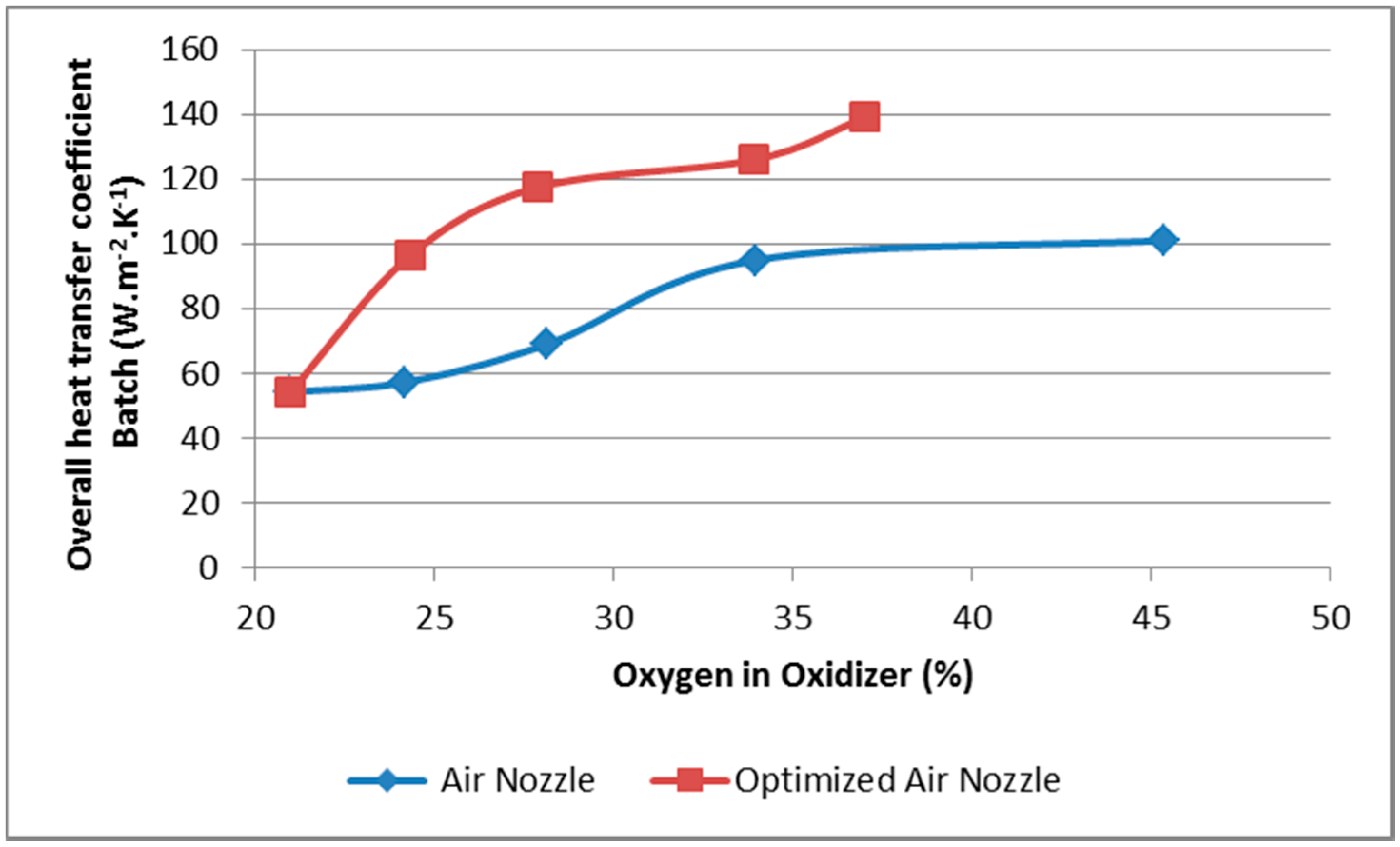
  • The increase of the overall heat transfer coefficient to the charge by 32%–70%, depending on the oxygen concentration;
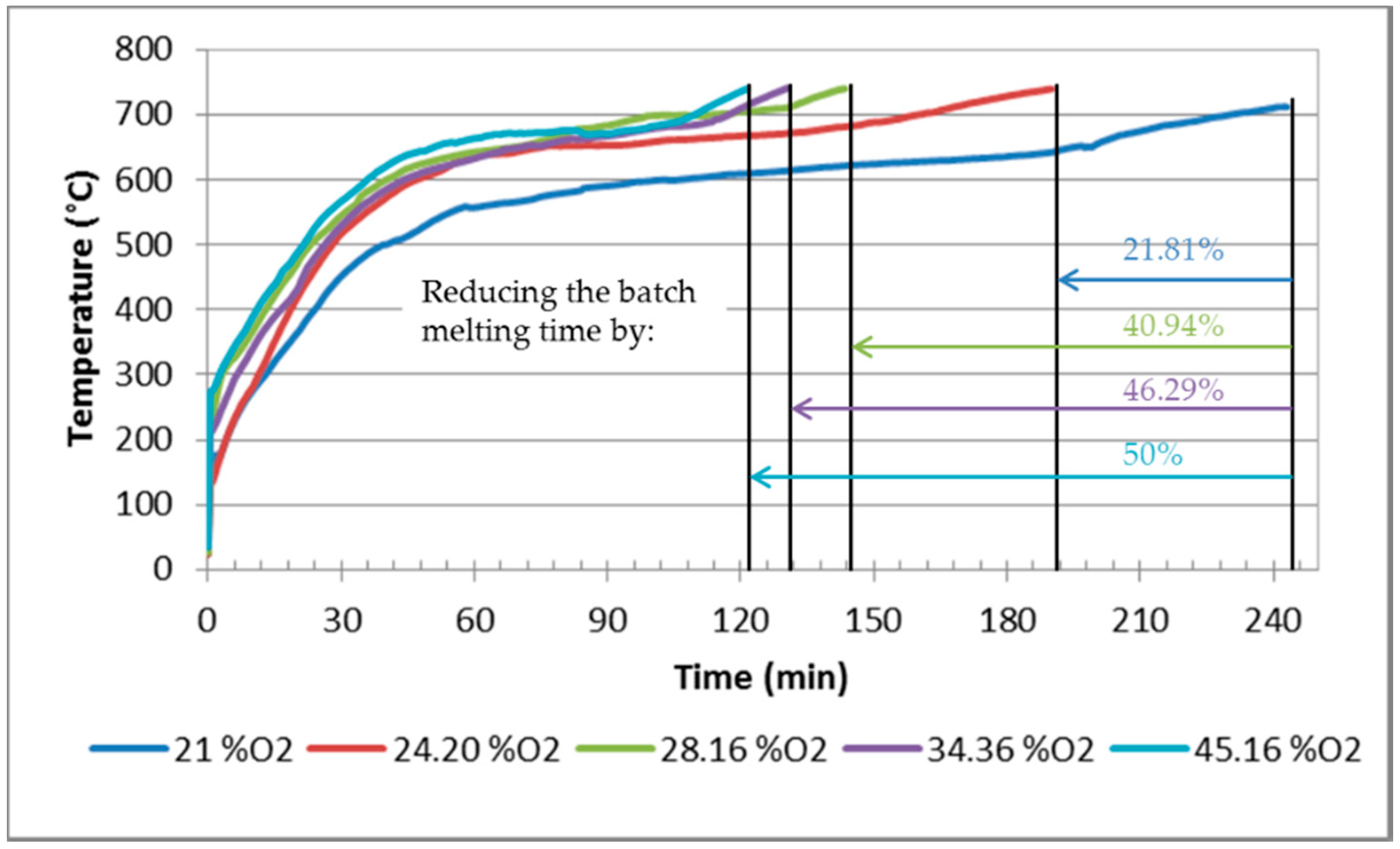
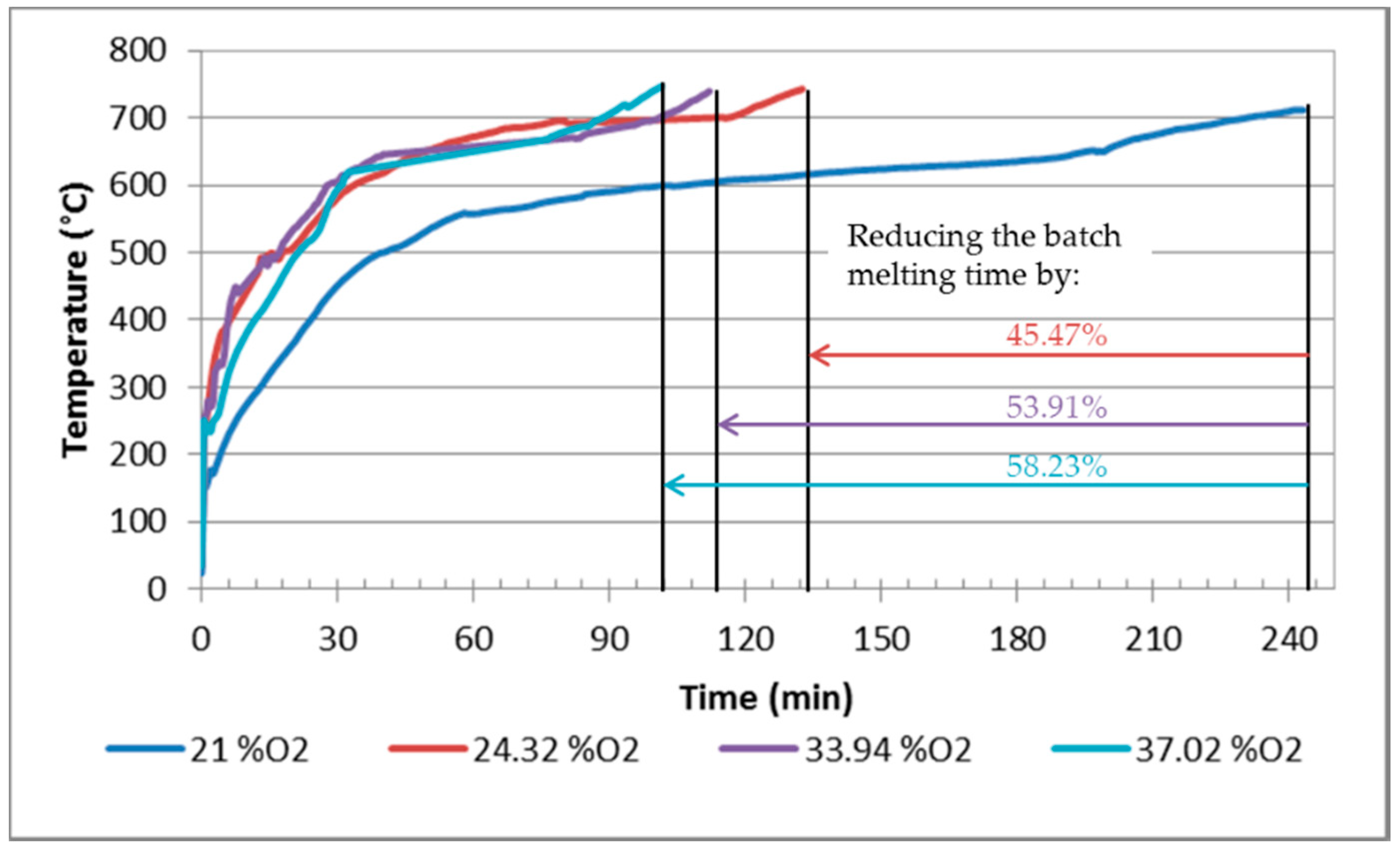
  • The shortening of the melting time by 12% and 24% (at an oxygen concentration of 35% and 25%, respectively);
  • The increase of the thermal efficiency of devices (by 4% in the experimental device);
  • The decrease of the nominal energy consumption for melting the charge by 20%–30%, depending on the oxygen concentration.
In connection with the energy consumption for heating and melting of the charge, which is determined by the melting time, it is also necessary to emphasise that the main contribution of the air nozzle optimisation design is reflected mainly in the input cost reduction for fuel and oxygen, recalculated per 1 kg of charge. From the environmental point of view, the main benefit is the reduction of emissions released to the atmosphere. The results of the laboratory measurements confirmed that the optimum oxidizer enrichment by oxygen for aluminium melting in rotary furnaces with the ordinary air nozzles is 35%.
The results show that the enrichment of the oxidation mixture is only one of the factors influencing the heating, melting, and overheating processes of the charge. The optimisation of the burner parameters also has a significant impact on the heat consumption and, therefore, on the amount of fuel burned, oxygen used, and emissions produced at lower enrichment levels. With the expected improvement of the optimum oxygen concentration in melting aluminium materials using the optimised air nozzle, the experimental measurements performed show that further research in this field is possible.
The results obtained reflect trends in EU energy policy and, therefore, research in the field is useful and highly topical.

Author Contributions

R.D., A.V., and G.J. carried out comprehensive experimental measurements; A.V. and G.J. compiled the measurement methodology; R.D. and A.V. processed the measurement results; L.L. helped in the experiment; R.D. and J.K. wrote the article.

Funding

This research was funded by [VEGA MŠVVaŠ SR a SAV] grant number [1/0691/18].

Acknowledgments

This publication was supported by the VEGA 1/0691/18 project and obtained results are a part of the solution from this grant project.

Conflicts of Interest

The authors declare no conflict of interest. The founding sponsors had no role in the design of the study; in the collection, analyses, or interpretation of data; in the writing of the manuscript, and in the decision to publish the results.

References

  1. Organization for Economic Cooperation and Development (OECD). Material Case Study 2: Aluminium, in OECD Global Forum on Environment; OECD: Paris, France, 2010; Available online: https://www.oecd.org/env/waste/46194971.pdf (accessed on 10 October 2018).
  2. Schlesinger, M.E. Aluminium Recycling, 2nd ed.; CRC Press: Boca Raton, FL, USA, 2014; ISBN 9781138073043. [Google Scholar]
  3. Gripenberg, H.; Falk, O.; Olausson, R.; Niedermair, F. Controlled melting of secondary aluminum in rotary furnaces. In Proceedings of the Light Metals 2003: Technical Sessions Presented by the TMS Aluminium Committee at the 132nd TMS Annual Meeting, San Diego, CA, USA, 2–6 March 2003; Crepeau, P.N., Minerals, Metals and Materials Society, Eds.; TMS: Warrendale, PA, USA, 2003; pp. 1083–1090. [Google Scholar]
  4. Furu, J.; Buchholz, A.; Bergstrøm, T.H.; Marthinsen, K. Heating and melting of single Al ingots in an aluminum melting furnace. In Proceedings of the Light Metals 2010: Technical Sessions Presented by the TMS Aluminum Committee at the TMS 2010 Annual Meeting & Exhibition, Seattle, WA, USA, 14–18 February 2010; Johnson, J.A., Ed.; TMS-AIME: Warrendale, PA, USA, 2010; p. 679. [Google Scholar]
  5. Naranjo, R.J.; Kwon, J.; Majumdar, R.; Choate, W.T. Advanced Melting Technologies: Energy Saving Concepts and Opportunities for the Metal Casting Industry; U.S. Department of Energy: Washington, DC, USA, 2005. Available online: https://www1.eere.energy.gov/manufacturing/resources/metalcasting/pdfs/advancedmeltingtechnologies.pdf (accessed on 12 October 2018).
  6. Jablonský, G.; Pástor, M.; Dzurňák, R. Enriching the Combustible Mixture with Oxygen in Practice; TU of Košice: Košice, Slovakia, 2015; ISBN 978-80-5532414-2. (In Slovak) [Google Scholar]
  7. Gel, V.I.; Rudakov, D.N. Development of aluminium scrap melting technology. Non-Ferr. Met. 2013, 2, 35–39. [Google Scholar]
  8. Gripenberg, H.; Johansson, A.; Eichler, R.; Rangmark, L. Optimised oxyfuel melting process at sapa heat transfer ab. In Proceedings of the Light Metals 2007: Technical Sessions Presented by the TMS Aluminum Committee at the TMS 2007 Annual Meeting & Exhibition, Orlando, FL, USA, 25 February–1 March 2007; Sorlie, M., Minerals, Metals and Materials Society, Eds.; TMS: Warrendale, PA, USA, 2007; pp. 597–601. [Google Scholar]
  9. Jepson, S.; Kampen, P.V. Oxygen-enhanced combustion provides advantages in al-melting furnaces. Ind. Heat. 2005, 72, 29–35. [Google Scholar]
  10. Saha, D.; Baukal, C.E. Nonferous Metals. In Oxygen-Enhanced Combustion, 1st ed.; Baukal, C.E., Ed.; CRC Press: Boca Raton, FL, USA, 1998; ISBN 9780849316951. [Google Scholar]
  11. Gluns, L.; Schemberg, S. Advantages of oxyfuel burner systems for aluminium recycling. Alum. World 2002, 2, 107–110. [Google Scholar]
  12. Poskart, A.; Radomiak, H.; Niegodajew, P.; Zajemska, M.; Musiał, D. The Analysis of Nitrogen Oxides Formation During Oxygen—Enriched Combustion of Natural Gas. Arch. Metall. Mater. 2016, 61, 1925–1930. [Google Scholar] [CrossRef]
  13. Wu, K.K.; Chang, Y.C.; Chen, C.H.; Chen, Y.D. High-efficiency combustion of natural gas with 21–30% oxygen-enriched air. Fuel 2010, 89, 2455–2462. [Google Scholar] [CrossRef]
  14. Baukal, C.E., Jr. Industrial Burners Handbook, 1st ed.; CRC Press: Boca Raton, FL, USA, 2004; ISBN 9780203488805. [Google Scholar]
  15. Baukal, C.E. Heat Transfer in Industrial Combustion, 1st ed.; CRC Press: Boca Raton, FL, USA, 2000; ISBN 9780849316999. [Google Scholar]
  16. Baukal, C.E., Jr. Oxygen-Enhanced Combustion, 2nd ed.; CRC Press: Boca Raton, FL, USA, 2013; ISBN 9781439862285. [Google Scholar]
  17. Redr, M.; Prihoda, M. Fundamental of Thermal Technology, 1st ed.; SNTL: Praha, Czech Republic, 1991; ISBN 80-03-00366-0. (In Czech) [Google Scholar]
  18. ANSYS® Academic Research Mechanical, Release 18.1, Help System. Coupled Field Analysis Guide; ANSYS, Inc.: Canonsburg, PA, USA, 2018. [Google Scholar]
  19. Andersen, J.; Rasmussen, C.L.; Giselsson, T.; Glarborg, P. Global combustion mechanisms for use in CFD modeling under oxy-fuel conditions. Energy Fuel 2009, 23, 1379–1389. [Google Scholar] [CrossRef]
  20. Bibrzycki, J.; Poinsot, T.; Zajdel, A. Investigation of Laminar Flame Speed of CH4/N2/O2 Mixtures Using Reduced Chemical Kinetic Mechanisms. Arch. Combust. 2010, 30, 287–296. [Google Scholar]
  21. Levenspiel, O. Chemical Reaction Engineering, 3rd ed.; John Wiley & Sons: New York, NY, USA, 1999; ISBN 0-471-25424-X. [Google Scholar]
  22. SPP-Distribucia. Available online: http://www.spp-distribucia.sk/sk_distribucna-siet/sk_zlozenie-zemneho-plynu-a-emisny-faktor (accessed on 15 October 2018).
Figure 1. Experimental model of the tilting rotary furnace.
Applsci 09 01614 g001
Figure 2. A schematic diagram of the experimental device.
Applsci 09 01614 g002
Figure 3. (a) Schematic presentation of the gas and oxidizer flow; (b) Formation of the combustion mixture.
Applsci 09 01614 g003
Figure 4. Graphical dependence of the emissivity of flue gas εFG, εCO2, and εH2O from the oxidizer oxygen concentration (mathematical modelling).
Applsci 09 01614 g004
Figure 5. The temperature fields of the experimental device using ordinary air nozzles (on the left) and optimized air nozzles (on the right) for various levels of the oxidizer oxygen enrichment.
Applsci 09 01614 g005
Figure 6. Comparison of energy consumption per 1 kg of charge depending on the oxidizer oxygen concentration (Adapted from [9], calculated from the experimental measurement).
Applsci 09 01614 g006
Figure 7. Comparison of the available heat and energy efficiency depending on the oxidizer oxygen concentration and burner type (calculated on the basis of the measurement results).
Applsci 09 01614 g007
Figure 8. Temperature of the charge during the process of aluminium ingot melting as a function of the oxygen concentration, using the ordinary air nozzle.
Applsci 09 01614 g008
Figure 9. Temperature of the charge during the process of aluminium ingot melting as a function of the oxygen concentration, using the optimised air nozzle.
Applsci 09 01614 g009
Figure 10. The increase in the specific heat of the charge during the aluminium ingot melting process, related to the change of the oxidizer oxygen concentration using an ordinary air nozzle.
Applsci 09 01614 g010
Figure 11. The increase in the specific heat of the charge during the aluminium ingot melting process related to the change of the oxidizer oxygen concentration using an optimised air nozzle.
Applsci 09 01614 g011
Figure 12. Heat flux density depending on the oxidizer oxygen concentration for the ordinary and optimised air nozzles (calculated on the basic of the measurement results).
Applsci 09 01614 g012
Figure 13. Theoretical combustion temperature including dissociation and flue gas volume per unit of NG (natural gas) as a function the oxygen concentration in the oxidizer (calculated on the basis of the mathematical model).
Applsci 09 01614 g013
Table 1. Volume flows of the inlet media depending on the oxygen concentration in the oxidiser.
ParameterUnitValue
Burner powerkW13.5
Excess of combustion air-1.1
Oxygen enrichment%2125303540
Gas flowm3 h−11.321.321.321.321.32
Air flowm3 h−114.3311.428.897.075.71
Oxygen Flowm3 h−1-0.611.141.521.8
Diameter of Nozzle (D1)m0.0440.0260.0230.0190.016
Table 2. Natural gas composition (Adapted from [22]).
CH4C2H6C3H8C4H10C5H12C6H14CO2N2
%%%%%%%%
95.1712.71310.87290.27720.04860.02070.22660.6697

