1. Introduction
Traditional endoscopic sinus surgery is usually performed by a surgeon with a left-handed nasal endoscope and right-handed surgical instruments. The surgeon’s hands are prone to fatigue and shaking due to the long operation, which may cause misoperation. Additionally, for some complicated operations, the assistant surgeon is required to hold the endoscope while the chief surgeon operates with both hands. Surgical operations between surgeons are easily interfered, and coordination is difficult. Introducing a robot to assist the surgeon to hold the endoscope, acting as the surgeon’s third hand, can combine the advantages of the robot with the surgeon’s experience, so that the surgeon can change the one-hand operation mode to a two-hand operation mode, thus the stability of the operation can be enhanced and the quality and safety of the operation can be improved.
Currently available robots for endoscopic sinus surgery can be divided into two categories: Passive surgical robots and active surgical robots. Active surgical robots include single-arm surgical robots, multi-arm surgical robots, and single-port type surgical robots. From the perspective of control, there are mainly three control modes. The first mode is the passive control mode, in which the surgeon locks or loosens the robot joints by operating buttons, pedals, etc., and constantly drags and adjusts the posture of the robot. This passive control mode is simple and reliable, and can meet the requirements of minimally invasive surgery to a certain extent, for example, the surgical robot Tiska [
1] developed by Karl Storz, the Point Setter and UniARM [
2,
3] developed by Mitaka, and the EndoArm [
4,
5,
6] developed by Olympus. Although the above passive control mode can basically realize the function of assisting surgeon in holding the endoscope in surgery, the robot still needs the surgeon to manually operate the button, pedal, etc. to loosen or lock all the joints, and the control has low efficiency and low intelligence. The second mode is the active control mode, in which the surgeon’s head movement and voice are used to control the motion of the robot. For example, the active surgical robot, Aesop [
7,
8,
9,
10], can use the voice control mode to drive the endoscope at the end of the robot to the desired spatial pose; the surgical robot, Endo Assist [
11,
12], can control the motion of the endoscope at the end of the robot with the movement of the surgeon’s head. The third mode is the master-slave control mode, which is often used in multi-arm surgical robot systems, such as Laprotek [
13,
14], Zeus [
15,
16,
17], Da Vinci [
18,
19], Miro Surge [
20,
21,
22,
23], and Raven [
24,
25]. The surgeon controls the slave robot arms at the main console, and switches the control of each slave arm by pedals. The ratio of the surgeon’s input motion to the output motion of the robot can be adjusted in the master-slave control mode, achieving finer operation than the human hand. At the same time, the signal-filtering algorithm can eliminate the influence of the surgeon’s hand tremor, improving the quality of surgery. According to the above analysis, the passive control mode is simple and reliable, but the surgeon needs to manually adjust the posture of the nasal endoscope during the operation; the adjustment is awkward and has a low level of automation. The master-slave control mode is generally applicable on active surgical robots in the form of a multiple-arm, such as the Da Vinci robot. Considering that the end-effector of the multi-arm form robot is generally large in size, it can only be applied to the types of surgery that have a large operation space, such as abdominal cavity surgery, and it cannot be applied to types of surgery with a small operation space, such as the nasal cavity. For the active control mode based on the voice and head movement, the human–robot interaction efficiency is low, and the training time is long, which requires further research.
For robot-assisted endoscopic sinus surgery, due to the narrow and complex anatomy of the nasal cavity, the endoscope easily collides and interferes with the nasal tissue. To ensure the safety of the operation, it is necessary to restrain the movement of the endoscope at the end of the robot. Presently, there are two main motion constraint methods for robots: Hardware constraint based on robot structure design and software constraint based on algorithms. Hardware-based constraint is generally considered to be more safe, but often less flexible, such as RCM (remote center of motion) constraint. VF (virtual fixture) represents one of the most important software-based constraints, which was proposed by Professor Rosenberg [
26,
27] in 1993. VF is a constraint method that uses an algorithm to generate invisible spatial motion constraint, thereby limiting robot motion. Current VF can be divided into GVF (guiding virtual fixture) and FRVF (forbidden regions virtual fixture) [
28]. A GVF is generally used to guide the end-effector of the robot to move along a predefined trajectory to avoid interference; an FRVF is generally used to prevent the end-effector of the robot from entering a specific area and can be used to protect critical tissues and organs during surgery. Park et al. [
29] prevented the robot end-effector from entering a specific area by constructing a VF "virtual wall" in robot-assisted cardiac surgery and verified the effectiveness of the VF through simulation. Prada et al. [
30] proposed a VF library design method by introducing VF into the virtual reality system. Ren et al. [
31] proposed a dynamic VF design method for minimally invasive cardiac surgery, in which the interpolation algorithm was used to calculate the dynamic VF at different moments in the heartbeat cycle to avoid the probe entering the dangerous area during operation. Hu et al. [
32] restricted the movement of the end-effector of a spinal surgical robot by introducing a GVF (straight type) and an FRVF (cone type) to improve the safety of the operation. Li et al. [
33,
34,
35] used an optimization constraint algorithm to generate VFs to solve the problem of a narrow operating space in endoscopic sinus surgery, but the algorithm is too complicated and does not consider nasal soft tissue. In summary, the existing VF research is mainly based on regular geometric shapes. Due to the complex and narrow anatomical structure of the human nasal cavity, the use of regular geometric shapes as a motion constraint will result in the loss of substantial valuable operation space, which is not allowed in the surgical operation. Therefore, it is urgent that the problem regarding how to properly fit the VF model with a 3D anatomical structure of the human nasal cavity is solved and the safety constraint of the nasal endoscope’s movement is realized.
Based on the above control mode and safety constraint analysis, considering the current clinical requirements of endoscopic sinus surgery, this paper proposes a human–robot cooperative control method based on VFs in robot-assisted endoscopic sinus surgery. This method uses admittance-based cooperative control to realize human–robot interaction between the surgeon and robot during surgery; the VFs are used to restrain and guide the movement of the robot, thereby ensuring the movement safety of the nasal endoscope. The experimental results showed that the robot can assist the surgeon in holding the endoscope in the endoscopic sinus surgery with the proposed method, and the surgical operation is more accurate and safer during surgery.
The remainder of this paper is organized as follows. The robot motion constraint model based on VF is presented in
Section 2. The human–robot cooperative control method is detailed in
Section 3. The experiment and discussion are presented in
Section 4, and the conclusions are summarized in
Section 5.
2. Robot Motion Constraint Model Based on Virtual Fixture
The narrow and complex anatomical structure of the nasal sinus makes it easy for the endoscope at the end of the robot to interfere with the nasal tissue, and the entire surgical operation space is very crowded. To ensure the safety of the surgical operation, it is necessary to restrain the movement of the endoscope. The VF can construct invisible "clamps" (e.g., spatial curves and surfaces) to assist the operator to improve operational efficiency and accuracy. In this section, the robot motion constraint requirements for each motion stage during endoscopic sinus surgery are determined based on the endoscope’s trajectory analysis. Next, based on the obtained motion constraint requirements, three typical VF models suitable for endoscopic sinus surgery are constructed. Finally, based on the three typical VF models, a composite VF model is constructed to achieve the robot constraint for the whole endoscopic sinus surgery.
2.1. Motion Constraint Requirements Analysis
Generally, the trajectory of the endoscope at the end of the robot in endoscopic sinus surgery is shown in
Figure 1.
It can be seen from
Figure 1 that the movement of the endoscope can be mainly divided into four stages:
The first stage is from point A to point B: The endoscope moves from a safe area away from the patient (point A) to the vicinity of the patient’s nasal inlet (point B). In this stage, since the endoscope is far away from the patient, it is not easy to collide with the patient. Therefore, it is only necessary to construct a plane-based FRVF to prevent the endoscope from colliding with the patient.
The second stage is from point B to point C: When the endoscope moves further from point B to point C, the endoscope gradually approaches point C at the patient’s nasal inlet. To prevent the endoscope from colliding with the patient during this stage, a single-leaf hyperboloid based FRVF is constructed to guide and constrain the movement of the endoscope to prevent it from colliding with the patient’s nasal inlet.
The third stage is from point C to point D: When the endoscope moves from point C at the inlet of the nose to point D in the surgical area, the endoscope movement path is in the nasal cavity of the patient. Due to the narrow and complex anatomy of the nasal cavity, the endoscope easily collides with the nasal tissue during surgery; thus, a VF based on a spatial curve is constructed to guide the motion of the robot.
The fourth stage: After the endoscope reaches the surgical area, the surgeon constantly adjusts the endoscope posture to obtain a suitable surgical vision field according to the needs of the operation. To prevent collision and interference between the endoscope and nasal tissue, an FRVF based on the anatomical structure of the nasal cavity is constructed to constrain the motion of the endoscope.
2.2. Virtual Fixtures for Endoscopic Sinus Surgery
Based on the above robot motion constraint requirement analysis, the main types of VFs in endoscopic sinus surgery can be obtained as follows: GVF based on the spatial curve, FRVF based on the plane and hyperboloid, and FRVF based on the anatomical structure of the nasal cavity. Their action mechanisms and implementation processes are shown below.
2.2.1. Guiding Virtual Fixture Based on Spatial Curve
For the geometry of GVFs, there are mainly straight line, two-dimensional curve, three-dimensional curve, etc. However, for the robot system, considering the smoothness and computational complexity of the motion trajectory, the cubic polynomial spatial curve is mostly used.
As shown in
Figure 2a, the schematic diagram of the GVF based on a spatial curve is shown. Assuming that the coordinates of the robot end are
, the velocity of the robot end is
, and the curve, S, is the guiding spatial curve, the velocity of the robot end can be decomposed into the velocity along the tangential direction and velocity in the direction perpendicular to the tangential direction:
Introducing a guiding stiffness coefficient,
, to scale the velocity in the perpendicular tangential direction, the following is obtained:
Thus, the velocity of the robot end after the action of the GVF can be obtained as follows:
For the above GVF, different guiding requirements can be achieved by setting different values of the guiding stiffness coefficient. When , the velocity of the robot end remains unchanged before and after guidance, the VF does not work, and the robot is in a free motion state. When , the velocity in the perpendicular tangential direction of the robot end is reduced, so the robot will be directed to the curve, S. When , the velocity of the robot end in the perpendicular tangential direction is completely removed and the robot end will be forced to move in the tangential direction of the curve, S. From the above, the smaller the guiding stiffness coefficient is, the stronger the motion guidance to the robot end obtained.
The above situation is the velocity guidance under ideal conditions. In practical applications, the end of the robot is generally not on the spatial curve, so that the motion trajectory of the robot end will be a curve parallel to the guiding curve.
Figure 2b shows the action of the GVF when the robot end is not on the guiding curve. Assume
is the closest point on the curve to the robot end, then:
Adding a regression coefficient,
, then the regression velocity can be calculated as follows (direction is pointed to
from
):
By adjusting the regression coefficient, the velocity of the robot end returning to the curve can be adjusted, and then the final velocity can be obtained:
From the above analysis, it can be seen that different guiding requirements of the GVF can be realized by adjusting the guiding stiffness coefficient, k, and the regression coefficient, .
The above derivation process of the GVF based on the spatial curve can be applied to the straight line, the two-dimensional curve, and so on because they can be regarded as a special case of the spatial curve.
2.2.2. Forbidden Virtual Fixture Based on Hyperboloid
The FRVF can limit the operating range of the robot and prevent the robot from entering a specific area, thereby avoiding collision between the instrument and tissue during operation. For the FRVF, how to construct appropriate geometries to constrain the workspace of the robot is an important issue to be considered in the application of the surgical robot. Considering that the endoscope and instrument swing around the nostril to form a workspace similar to the "funnel" shape [
36], a single-leaf hyperboloid is used as the geometry of the FRVF.
The schematic diagram of the FRVF based on a single-leaf hyperboloid is shown in
Figure 3. Assuming that the position of the robot end is
, and the velocity of the robot end is
(direction as
), the equation of the single-leaf hyperboloid, S, is shown below:
The action process of the FRVF based on a single-leaf hyperboloid is as follows:
1) According to the position of the robot end and Equation (7), the spatial relationship between and the single-leaf hyperboloid is judged.
2) If , the robot end, , is inside the single-leaf hyperboloid, the FRVF does not work, and the robot end is in the free motion state, its velocity, , remains unchanged.
3) If , the robot end is outside the single-leaf hyperboloid, the velocity of the robot end will be changed by the FRVF. If , the velocity of the robot end is in the same direction as the normal vector, , of the tangent plane, , indicating that the robot end is leaving the prohibited area of the VF; if , the velocity of the robot end is opposite to the normal vector, , of the tangent plane, , indicating that the robot is entering the prohibited area of the VF. In the above two cases, the velocity of the robot needs to be adjusted.
By projecting the velocity vector,
, onto the normal,
, and tangent planes,
(the
direction is along the direction of
, the
direction is along the direction of
), the following can be obtained:
Introducing the forbidden stiffness coefficient,
, the input velocity can be expressed as follows:
When and is in the same direction, if , the robot end will continue to enter the prohibited area; if , the robot end will leave the prohibited area. When and is in the reverse direction, if , the robot end will leave the prohibited area; if , the robot end will continue to enter the prohibited area. In the whole process, the velocity of the robot can be adjusted to leave the forbidden area by applying different values of .
The above derivation process of the FRVF based on the single-leaf hyperboloid is applicable to other three-dimensional surface geometries, such as the plane, except that the method of solving the tangent plane of the nearest point is different.
2.2.3. Forbidden Virtual Fixture Based on the Anatomical Structure of the Nasal Cavity
When the robot end enters the inlet of the nasal cavity, due to the complex anatomy of the nasal cavity, the VF based on regular geometry (e.g., cylinder and cone) is used to constrain the movement of the robot, which will lose substantial precious operation space, and is not allowed during endoscopic sinus surgery. Therefore, in this section, a point cloud model is obtained based on the CT image sequence of the patient’s nasal tissue, based on which an FRVF suitable for the nasal cavity is constructed. The boundary of the FRVF coincides with the boundary of the nasal tissue, thereby maximally retaining the operation space while protecting the nasal tissue.
Figure 4 shows the schematic diagram of the FRVF based on the anatomical structure of the nasal cavity.
The FRVF works as follows:
1) Assuming that the position of the endoscope tip is
, the corresponding pixel point,
, of the endoscope tip in the binarized point cloud model can be obtained as follows:
where
,
, and
represent the origin coordinates of the binarized point cloud model of nasal tissue;
,
, and
represent the pixel spacing in the x, y, and z coordinate directions of the nasal tissue binarized point cloud model; and INT() represents the rounding function.
2) Assuming that the search radius of the endoscope tip is
R, it can be determined that the local search range of the collision detection is:
3) For the pixels in the local search range, the Euclidean distance from the pixels to the endoscope tip is calculated as follows:
4) If the pixel value of the local pixel is 0, it indicates the pixel is a free spatial point and is shown with the black color in
Figure 4. There is no collision in this case, the endoscope is in a free motion state, and the FRVF does not work. If the pixel value of the local pixel is 255, it indicates the pixel is a nasal tissue point and is shown with the white color in
Figure 4. There is a collision in this case. Since the surface of the human nasal sinus is a thin layer of mucous membrane, considering the safety of the operation, the velocity of the endoscope is set to zero, which means the robot immediately stops moving, protecting the nasal tissue of the patient.
2.3. Overall Robot Motion Constraint Model Based on Virtual Fixture
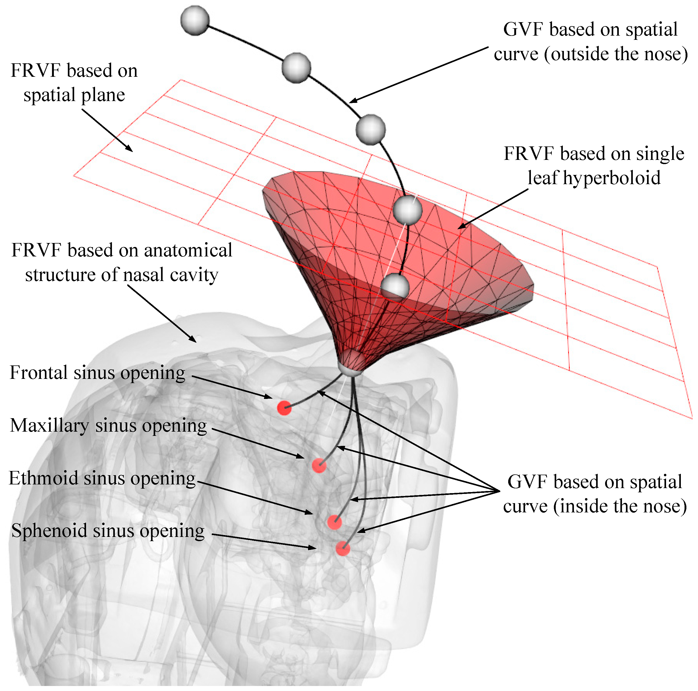
Through the analysis in the above section, several typical VF types suitable for endoscopic sinus surgery have been obtained. Considering that it is difficult for a single VF to meet the diverse constraint requirements during different stages of robot-assisted endoscopic sinus surgery, a composite VF is constructed based on the above typical VFs, and the overall robot motion constraint model is obtained, as shown in
Figure 5.
After multiple VFs are combined, the working condition and scope of each basic VF have been changed to avoid conflicts among the basic VFs. Based on the robot-assisted endoscopic sinus surgery procedure, the process of the composite VF system is shown in
Figure 6.
The detailed process of the composite VF is as follows:
1) Enter the coordinates, , and velocity, , of the endoscope tip in the composite VF system.
2) Calculate the directed distance, , from the endoscope tip to the constraint plane (plane normal direction is positive). If , indicating the endoscope tip is above the constraint plane, the robot can move freely in all directions, and go to step (7); if , indicating the endoscope tip is below the constraint plane, go to step (3).
3) Calculate the spatial relationship between the endoscope tip and nasal entrance point (RCM point) (the direction of the single-leaf hyperboloid opening is positive). If , it means that the endoscope tip is above the nasal entrance point, go to step (4); if , it means that the endoscope tip is below the nasal entrance point, go to step (5).
4) Calculate the spatial relationship between the endoscope tip and single-leaf hyperboloid (if the endoscope tip is outside the single-leaf hyperboloid, the is positive). If , it means the endoscope tip is outside the single-leaf hyperboloid, go to step (6); if , it means the endoscope tip is inside the single-leaf hyperboloid, the robot can move freely in all directions, go to step (7).
5) The endoscope enters the RCM restraint state, and the movement of the endoscope will be constrained to two rotational degrees of freedom around the RCM point, go to step (7).
6) Compare the distance from the endoscope tip to the constraint plane and distance from the endoscope tip to the single-leaf hyperboloid. If , it means the endoscope tip is close to the constraint plane, and the plane constraint is used to deal with the velocity of the endoscope tip; if , it means the endoscope tip is close to the single-leaf hyperboloid, and the velocity of the endoscope tip is processed by the single-leaf hyperboloid constraint. Go to step (7).
7) Calculate the distance between the endoscope tip and the point cloud model of the nasal tissue. If , it means that there is no interference between the endoscope tip and nasal tissue, and the robot can move freely in all directions; if , it means that the endoscope tip and nasal tissue are interfering. The robot stops moving.
5. Conclusions
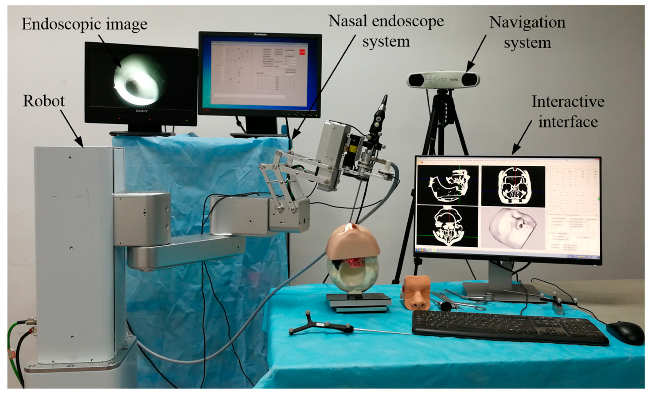
This paper proposed a human–robot cooperative control method based on VF to improve the accuracy and safety of surgical operation in robot-assisted endoscopic sinus surgery. Firstly, based on the analysis of endoscopic motion constraint requirements in different surgical stages, three typical VFs suitable for endoscopic sinus surgery were designed and implemented. The GVF based on a spatial curve was designed to achieve motion guidance from the nasal cavity entrance to the operating area. Considering the funnel-shaped workspace of the endoscope, the FRVF based on the single-leaf hyperboloid was designed to achieve motion constraints at the entrance to nasal cavity. The FRVF based on the anatomical structure of the nasal cavity was designed to constrain the motion of the endoscope inside the nasal cavity, the boundary of which coincides with the boundary of the nasal tissue, thereby maximally retaining the precious operation space while protecting the nasal tissue. Thereafter, a composite VF was constructed based on the above typical VFs, and an overall robot motion constraint model was obtained. Secondly, based on the obtained robot motion constraint model, a human–robot cooperative control method based on VF was proposed. The method adopts admittance-based control to realize efficient human–robot interaction between the surgeon and robot during surgery, and the surgeon adjusts the endoscope to the desired posture by dragging the end of the robot. During the dragging process, the motion of the robot is restrained and guided by the VFs to prevent the endoscope at the end of the robot from interfering with the nasal tissue. With the proposed control method, the surgeon can free his left hand and carry out complex surgical operations with both hands, thus improving operation efficiency. Finally, validation experiments were conducted. The GVF experiment based on the cubic polynomial curve was performed and the results showed that the proposed GVF can effectively reduce the trajectory tracking error of the robot and improve the drag operation precision. The composite FRVF based on the spatial plane and a single-leaf hyperboloid was tested and the results showed that the proposed FRVFs can prevent the endoscope from colliding with the nasal tissue and improve the safety of the surgical operation. Thereafter, robot-assisted endoscopic nasal examination experiment was performed using a high-imitation head model, and the results showed that the proposed human–robot cooperative control method based on VF can effectively realize the motion guidance and constraint of the robot, and help to improve the accuracy and safety of operation during endoscopic sinus surgery. Considering clinical applicability, the project team is now working on clinical experiments to further optimize the robot system.

 and
and 