Article

A Robust Controller for Multivariable Model Matching System Utilizing a Quantitative Feedback Theory: Application to Magnetic Levitation

by
Ramamurthy Jeyasenthil
and
Seung-Bok Choi
*
Smart Structures and Systems Laboratory, Department of Mechanical Engineering, Inha University, Incheon 22212, Korea
*
Author to whom correspondence should be addressed.
Appl. Sci. 2019, 9(9), 1753; https://doi.org/10.3390/app9091753
Submission received: 4 March 2019 / Revised: 15 April 2019 / Accepted: 25 April 2019 / Published: 27 April 2019
(This article belongs to the Section Mechanical Engineering)

Abstract

:

Featured Application

The control scheme proposed in this work can be applied to several dynamics systems subjected to parameter uncertainties and external disturbances such as vehicle systems and robotic systems.

Abstract

This paper proposes a systematic feedback controller design methodology for multi-input multi-output (MIMO) uncertain systems using the quantitative feedback theory (QFT). To achieve this goal, the model matching problem was considered and the inversion feedforward controller was designed to improve control performance while reducing the demand on feedback control alone. The proposed method is formulated based on the concept of equivalent disturbance attenuation (EDA) approach in which the uncertain system problem is converted into an external disturbance rejection problem based on a nominal system. This proposed approach exhibiting non-sequential design method result in the suboptimal solution showing design simplicity and computational efficiency compared to the existing method. In order to validate the effectiveness of the proposed control methodology, the MIMO magnetic levitation system as adopted and control performances such as time response were presented in both time and frequency domains.

Graphical Abstract

1. Introduction

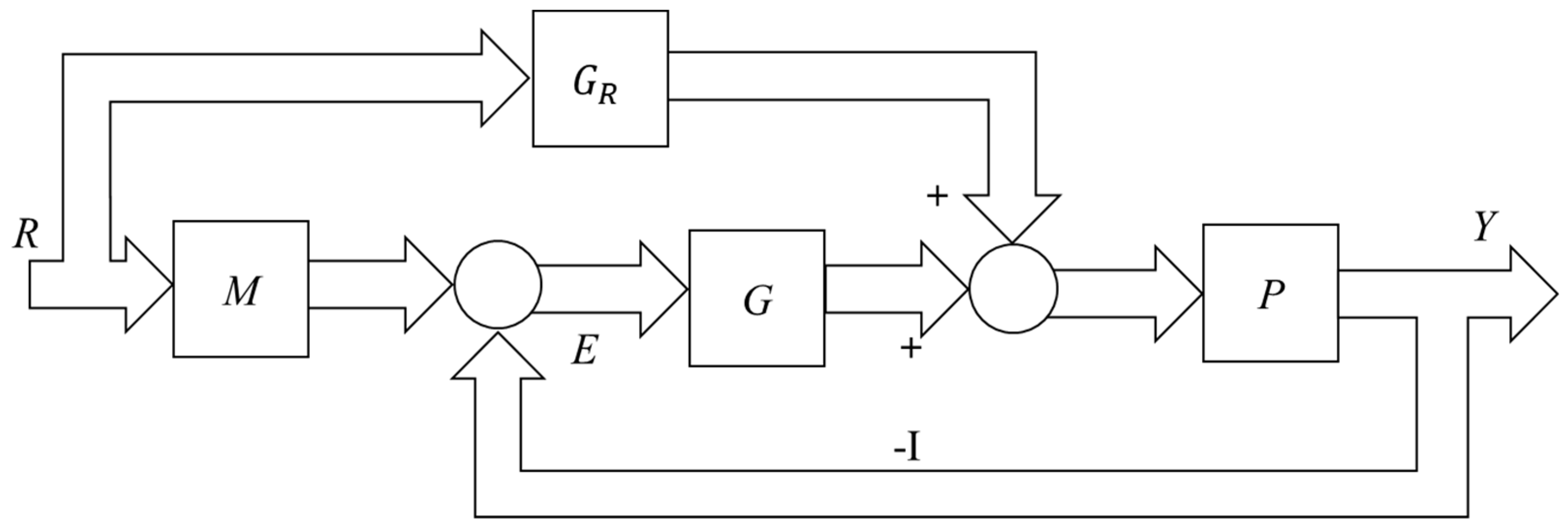
The fundamental limitations imposed by one degree of freedom (DOF) is overcome by the 2-DOF control structure and one such control is a combination of feedforward/feedback control as shown in Figure 1. Robust feedback control theory, such as quantitative feedback theory (QFT) [1], is essentially a 2-DOF structure containing a feedback controller (G) and a prefilter (F). The feedback controller is designed to desensitize the closed loop against the unknown (bounded) disturbance, system uncertainty to certain level, and the prefilter element is designed to satisfy the tracking specification. The main objective in QFT design is to minimize the feedback cost (high-frequency controller gain) which relates the bandwidth and sensor noise amplification [1]. In general, the MIMO design methodologies are generalized as the sequential design method and the non-sequential one [2]. In the former design, an equivalent single-input single-output (SISO) system considered is updated after each successive design and the latter one is design independent. These methods convert the MIMO design problem into a set of SISO equivalent design problems which in-turn has their own advantages and drawbacks. Tracking, disturbance attenuation and stability stand as the core problems in control systems [3]. The tracking problem in QFT is solved in two ways [4]: (i) classical tracking specification, keeping the magnitude of the tracking response within two given bounds [4,5], and (ii) tracking error specification (TES), establishing tolerances on the magnitude of the difference between certain reference models and the tracking transfer function [6,7]. In a TES approach (also known as model matching), phase information is captured in the specification, which has potential benefits for certain applications and reduction of overdesign as compared to the classical approach.
The tracking and disturbance rejection, performances can be improved by the feedforward controller without losing the robustness [8]. In general, the feedforward controllers are designed using the plant inversion technique [8,9] An inversion-based feedforward controller strategy improves the tracking performance relative to a pure feedback control as discussed in Reference [10] and the references therein. A sufficient condition for tracking performance is given as the plant uncertainty should be smaller than the size of the nominal plant divided by its condition number. The design of feedforward controller for the tracking problem in the MIMO process is addressed in Reference [11]. Based on the analytical decoupling technique, the feedforward signals are determined and the multi-objective optimization problem is solved to find the transition time of each output subject to actuator constraint, but it is not extended to uncertain systems. In the context of QFT, the multivariable model matching problem is addressed in Reference [6,7]. The drawbacks of these methods are over design, the prefilter design in Reference [7] is an approximation procedure and it may result in improper solutions. Recently, a novel MIMO QFT design methodology is proposed in Reference [4] to address both the model matching and the (uncertain) disturbance rejection problems. The approach derives the non-conservative controller bounds based on the quadratic inequalities which are computationally expensive for large number of uncertain parameters. This is due to the possible combination of pairing between the plants (in model matching problem) and/or between the plant and the disturbance (in disturbance rejection problem). The designer needs some experience for selecting the bound balancing coefficients and the tolerance tightening factors (the factors multiplying the tolerances) at each design frequency, so the Elso et al. method [4] is not so simple to use.
This motivates us to develop a simple and computationally efficient non-sequential design method. The approach we employed here is equivalent disturbance attenuation (EDA) concept. The EDA method has been applied to solve the classical tracking specification problem [12]. To the best of the authors’ knowledge, the EDA method is not explored for the MIMO TES problem with the inversion feedforward, except the work on single input single output (SISO) case in Reference [13]. Consequently, the main technical contributions are summarized as follows.
(1)
A computationally efficient and simple method to solve the multivariable TES problem with inversion feedforward for the large number of uncertain parameter is proposed.
(2)
The proposed formulation converts the original MIMO uncertain system into a set of equivalent SISO systems using the EDA concept. By doing this, it works on the nominal plant of the equivalent SISO system and the TES bounds for each of the SISO systems are computed by solving the single inequality at each phase.
(3)
The proposed method is free of pairing requirement and does not require any tuning factors as in the case of existing methods such as Elso et al. method [4].
(4)
The proposed approach is applied to the benchmark MIMO magnetic levitation system and a comparative work with existing methods is undertaken to demonstrate some advantages.
The rest of this paper is divided as follows. Section 2 states the problem statement. Section 3 discusses about the development of the proposed feedback controller design method for the model matching. The effectiveness of the new design approach is illustrated using a challenging and benchmark maglev system in Section 4 and Section 5 briefly concludes this work.
Notation: The (n × n) plant transfer matrix is denoted as P belonging to uncertain set P. The (n × n) diagonal feedback controller matrix is denoted as G and M that in turn denotes the (n × n) desired response model matrix. The notation GR denotes the (n × n) tracking feedforward controller matrix. The nominal element of the uncertain system is denoted by the subscript notation “0”. The notation “diag” represent the diagonal matrices. The (i, j)th element of the plant and the desired response model are denoted as pij and mij respectively. The dependence on s and is not written explicitly for ease in notation in the rest of this paper. The terms such as model matching and tracking, the on-channel (on-diagonal) and control loop are interchangeably used in the rest of the paper.

2. Problem Statement

Consider the feedforward–feedback control structure for the model matching problem as shown in Figure 2. The objective is to design the feedback controller G, the tracking feedforward controller GR such that the closed loop system must satisfy the following objectives:
  • For each plant P ∈ P, the closed loop is stable.
  • The model matching specification:
The transfer function matrix from the reference R to error E is denoted as Te = [teij] and the specification can be written as
| T e ( j ω ) | B e ( ω )
where, Be(ω) = [beij] is the tracking error tolerance at frequency ω. Element-wise it can be written as follows:
| t e i j | b e i j ; i , j = 1 , 2 , n

3. Feedback-Inversion Feedforward Design

3.1. Controller Design

This section describes the feedback controller design method for the model matching problem, i.e., in particular the bound generation inequalities (of an equivalent SISO problem) are derived. The transfer matrix from R to E can be written from Figure 2 as follows.
[ I + P G ] T e = [ M P G R ]
PP must be non-singular for the inverse to exist. Left multiply both the sides of Equation (3) by P0P−1 to get
[ P 0 P 1 + P 0 G ] T e = [ P 0 P 1 M P 0 G R ]
Define V: ≡ I − P0P−1, so P0P−1 = IV and the above equation becomes
[ I V + P 0 G ] T e = [ ( I V ) M P 0 G R ]
The nominal loop transmission matrix is defined as L0: ≡ P0G, so we can write the above equation as
[ I V + L 0 ] T e = [ M V M P 0 G R ]
The inversion-based strategy suggests [8,12] that the tracking feedforward controller as
G R = d i a g ( m 11 p 110 , , m i i p i i 0 )
Further, we can write the Equation (4) as,
[ I + L 0 ] 1 = T e [ D e ] 1
Equation (6) is implemented in Figure 3 with the equivalent disturbance term De = [MP0GRV (MTe)]. The plant uncertainty is transformed into an external output disturbance whose range is known, and hence, it is known as equivalent disturbance attenuation (EDA) method [12,14]. The feedback controller G and the feedforward controller GR is designed such that the closed-loop output (Te) satisfies the system tolerances over the entire De set, then the Schauder fixed point theory can be used to prove that the original MIMO specifications are satisfied [12].

3.2. Bound Generation Inequality

Equation (6) can be written element-wise by
1 1 + l i i 0 = t e i j ( m i j p i j 0 m i i p i i 0 1 ) ( v i j m i j + k j n v i k m k j ) + ( v i j t e i j + k j n v i k t e k j )
For i = j:
From Equation (7), we have the following equations.
1 1 + l i i 0 = t e i i ( m i i p i i 0 m i i p i i 0 1 ) ( v i i m i i + k i n v i k m k i ) + t e i i ( v i i + k i n v i k t e k i t e i i )
Further,
1 1 + l i i 0 = t e i i t e i i ( v i i + k i n v i k t e k i t e i i ) ( v i i m i i + k i n v i k m k i )
Here, the term ( t e k i t e i i ) captures the interaction specifications. Equation (9), in terms of the absolute magnitude, can be expressed as follows:
| 1 1 + l i i 0 | | t e i i | | v i i m i i + k i n v i k m k i | + | t e i i ( v i i + k i n v i k t e k i t e i i ) |
Replacing the |teii| term by the specification inequality (2) in (10) gives the following equation
| 1 1 + l i i 0 | b e i i | v i i m i i + k i n v i k m k i | + b e i i | v i i + k i n v i k t e k i t e i i |
For ij:
From Equation (7),
1 1 + l i i 0 = t e i j ( m i j p i j 0 m j j p j j 0 1 ) ( v i j m i j + k j n v i k m k j ) + t e j j ( v i j + k j n v i k t e k j t e j j )
Equation (12), in terms of absolute magnitude, the above inequality can be written further as (using the triangle inequality),
| 1 1 + l i i 0 | | t e i j | | ( m i j p i j 0 m j j p j j 0 1 ) ( v i j m i j + k j n v i k m k j ) | + | t e j j ( v i j + k j n v i k t e k j t e j j ) |
Inequality (13) can be then written further as follows.
| 1 1 + l i i 0 | | t e i j | | m i j p i j 0 m j j p j j 0 1 | + | ( v i j m i j + k j n v i k m k j ) | + | t e j j ( v i j + k j n v i k t e k j t e j j ) |
Replacing the |teij| and |tejj| terms in (14) by its specification inequality (2) gives,
| 1 1 + l i i 0 | b e i j | m i j p i j 0 m j j p j j 0 1 | + | ( v i j m i j + k j n v i k m k j ) | + b e i j | ( v i j + k j n v i k t e k j t e j j ) |
The nominal loop transmission function lii0 is designed to satisfy the Equations (11) and (15), i.e.,
| 1 1 + l i i 0 | m i n ( b e i i | p e i i v | , b e i j | p e i j v | )
where, | p e i i v | = | v i i m i i + k i n v i k m k i | + b e i i | v i i + k i n v i k t e k i t e i i |
| p e i j v | = | m i j p i j 0 m j j p j j 0 1 | + | ( v i j m i j + k j n v i k m k j ) | + b e j j | ( v i j + k j n v i k t e k j t e j j ) |
Inequality (16) is used to generate the TES bounds on lii0. Here, iith equivalent SISO system is termed as channel-ii.
Remark 1.
Inequality (17) is valid for low frequency range specifications [15].

4. Case Study: MIMO Magnetic Levitation System

Motion control of magnetic levitation system has become an increasingly important area of research for many engineering systems. Some of them are dual axis motion control [16], rotary table with 6-DOF [17], precision-positioning stages [18], maglev trains, and the reader can refer to the papers in References [19,20] for more applications. The proposed non-sequential design in Section 3 is illustrated by means of a challenging and benchmark magnetic levitation system [21]. The magnetic levitation system (refer to Figure 4a) is set up as the MIMO system (2 × 2) with two control loops: Channel-11 (Control loop-1) that consists of the lower magnet and coil. Input to this control loop is the voltage applied to lower coil to levitate the lower magnet and the output is displacement of lower magnet. Channel-22 (Control loop-2) consists of the upper magnet and coil. Input to this control loop is the voltage applied to upper coil to levitate the upper magnet and the output is the displacement of upper magnet. The displacement of the magnets produces interaction between the loops.
The objective was to design a “non-interacting” stable control system which satisfies the model matching specifications. The uncertain plant sets for MIMO configuration of a magnetic levitation system [21] are:
p 11 ( s ) = A s 2 B s 4 + C s 2 + D , p 12 ( s ) = E s 4 + C s 2 + D p 21 ( s ) = F s 4 + C s 2 + D , p 22 ( s ) = H s 2 + I s 4 + C s 2 + D
where, A = [1445; 1565], B = [944,000; 1,036,000], C = [1271; 1289], D = [391,800; 401,200], E = [205,600; 241,000], H = [2604; 2819], F = [214,100; 251,000], I = [1,608,000; 1,767,000].
The nominal plant values were A0 = 1565; B0 = 1,036,000; C0 =1289; D0 = 401,200; E0 = 241,000; H0 = 2819; F0 = 251,000; I0 = 1,767,000.

4.1. Design Specifications

  • Robust stability margins: Gain margin ≥ 6 dB, phase margin ≥ 45 degree and its corresponding M-circle magnitude was 1.2.
  • Model matching specification: The desired response model was given by
    M ( s ) = 916 s 3 + 39.76 s 2 + 354.9 s + 916.2 [ 1 0 0 1 ]
    And the tracking error tolerance wa written as follows.
    B e ( s ) = [ 0.055 s ( s 10 + 1 ) 0.1 s ( s 10 + 1 ) 0.1 s ( s 10 + 1 ) 0.07 s ( s 10 + 1 ) ]
  • Interaction of 10% between the channel outputs was allowed, i.e.,
    | t e 12 t e 22 | m a x 0.1 ,   | t e 12 t e 22 | m a x 0.1 ,     ω .  

4.2. System Analysis and Results

Figure 4b shows the Bode plot of the plant p11 (lower magnet) for 6561 randomly selected plants. Here, the phase shift occurs due to the resonance peak at frequencies 22.7, 25.6, and 27.3. The design frequency set is chosen to include all such resonance frequencies and it becomes Ω = [0.1; 0.25; 0.4; 0.5; 1; 2; 3.66; 5.5; 6.5; 9; 15; 20; 22.7; 23.2; 25.6; 27.3; 27.8; 50]. Because of this resonance, the control problem becomes a challenging one.

4.2.1. Feedforward (GR) and Feedback Controller (G) design

The inversion-based strategy suggests that the diagonal tracking feedforward controller GR = diag(gr11; gr22), as given in Table 1. The feedback controller bounds generated using the proposed method (inequality 17) are combined with the stability margin bounds, as shown in Figure 5a, along with the loop shaping plot for channel-11. The bound comparison between the proposed method and the pure feedback design is shown in Figure 5b. Figure 6 shows the nominal loop shaping plot for channel-22. The designed diagonal feedback controller is
G ( s ) = [ 1 ( s 4 + 1 ) ( s 8 + 1 ) s ( s 1000 + 1 ) 0 0 0.6 ( s 4 + 1 ) ( s 8 + 1 ) s ( s 1000 + 1 ) ]
In the loop shaping plot of channel-11 in Figure 5a, the nominal loop transmission function (l110) at ω ≈ 22.7 makes the phase shift of 180°. Similarly, the phase shift occurs at frequencies ω ≈ 25, 27.3. The phase change is due to the phase shift of p11 at these frequencies as seen in the bode diagram (Figure 4). Similarly, the same situation occurs for the nominal loop shaping (l220) plot of channel-22. Next, just for comparison purposes, a pure feedback design is done (independent design) [12]. The nominal loop shaping plots for the pure feedback controller (Gfb) are omitted for simplicity and the designed controller is given in Table 1.

4.2.2. Design Validation and Analysis

Figure 7 shows the tracking errors obtained with the proposed design for the on-diagonal element of the closed loop uncertain system. It shows that the magnitudes of the closed loop system (for 6561 randomly selected plants) remain within the limits specified by the tolerance (Be) in equation (18). The closed loop responses of the uncertain system (for 6561 random plants) for a unit step are shown in Figure 8. The responses with the proposed feedback controller design (Equation (19)) along with the feedforward controllers (refer to Table 1) for channels-11 and -22 track the desired model (M) responses within the tolerances (Be).
Figure 9 compares the control effort with the proposed design (G + GR) and the pure feedback controller (Gfb) for both the channels. It is seen that the control effort with the proposed feedback controller alone (G) was much less than the pure feedback controller (Gfb) and the combined feedback + inversion feedforward (G + GR) control. The biggest share of the control effort produced by the proposed feedback + inversion feedforward design was due to the inversion feedforward control as shown in Figure 9. In practice, this implies a reduction in actuator fatigue, savings in energy, and avoidance of noise-induced saturation as mentioned in Reference [21]. It was noted that the demand for the feedback control was very less because of the feedforward action. This reduces the feedback cost measured in terms of high frequency gain. Hence, the main purpose of the QFT design can be achieved.
To analyze the interaction effect, a unit step input signal was applied at time instant t = 0 s and t = 4 s, for channels-11 and -22, respectively. The closed loop responses of the uncertain system (for 6561 random plants) with the proposed feedback controller design (equation 19) along with the feedforward controllers (equation 19 and Table 1) for channels-11 and -22 track the desired model (M) responses within the tolerances (Be) as shown in Figure 10, while the interaction effects are within the limits of specification (<0.1).
Figure 11 compares the frequency response magnitude of the feedback controllers between the proposed method and the pure feedback method for both the channels. The proposed feedback controller (G) gives a high frequency (HF) gain reduction of 20 dB over the pure feedback design (Gfb) for both the channels. This implies that the proposed design is less sensitive to the sensor noise amplification problem (termed as “cost of feedback” in QFT). It is interesting to explore the experimental validation of the proposed design in the magnetic levitation system.

4.2.3. Comparison with an Existing TES Method

The bound generation quadratic equality of Elso et al. [4] method (Appendix in Reference [4]) involves “pairing” of two plants p111 and p112 from the plant set p11 (channel-11). The “pairing” has to be done for all possible pairs of plants from p11. Thus, it can become a computational bottleneck, when p11 is represented by a large number of plants, such as when the number of uncertain plant parameters is large. The number of plants in p11 considered is 38 = 6561 for a grid size of three and the plant pairs to be considered in quadratic inequality becomes 38 × 38 = 43,046,721. This requires very large computational time in method [4] due to “pairing requirement” in the specifications. The proposed method does not require “pairing” and it takes 0.5 sec for generating performance bounds in both the channels. Another drawback in Reference [4], the bound balancing values and the tolerance tightening factors are selected, such that performance bound reaches an optimal configuration. These values were chosen by tuning at each performance design frequency and it needs an experienced designer, so the Elso et al. method [4] is not simple. The proposed method does not require any tuning and is simple, computationally efficient. The Elso et al. method [4] can still be applied after manipulating the plant template using the special methods such as the interval math, the affine plant representation, or methods to compute the outer border of the template but this is beyond the scope of the paper.

5. Conclusions

This paper proposed a novel feedback controller design method for the multivariable model matching problem. The overall MIMO problem was converted into an equivalent SISO problem using the EDA concept. In addition, the feedforward controllers were designed based on the inversion approach to enhance control performances and reduce the feedback control demand. The bounds on the feedback controller have been generated using the algebraic inequality which is computationally efficient for large number of uncertain parameters and provides the fast engineering solution. The resulting solution achieved in this work is a suboptimal one and better than the pure feedback designs. In order to demonstrate some benefits of the proposed approach, the benchmark MIMO magnetic levitation system has been adopted as an illustrative example. It has been shown through a comparative work with an existing method that the proposed control strategy can provide design simplicity and less computational time and faster rising time. Future work will be on reducing the overdesign by using the iterative procedure and extend the proposed non-sequential method to sequential design.

Author Contributions

R.J. derived all equations and did computer simulations to achieve performance results and S.-B.C. created the idea and made the problem formulation. In addition, both authors wrote the paper together by carefully checking the main technical contribution and sound as well.

Acknowledgments

This work was supported by Inha University (Incheon, Korea) Research Grant in 2019.

Conflicts of Interest

The authors declare no conflicts of interest.

Data Availability

All data to achieve results are available upon request.

References

  1. Horowitz, I.M. Quantitative Feedback Design Theory; QFT Publications: Boulder, CO, USA, 1993. [Google Scholar]
  2. Horowitz, I.M. Quantitative synthesis of uncertain multi input-output system. Int. J. Control 1979, 30, 81–106. [Google Scholar] [CrossRef]
  3. Chen, M.J.; Desoer, C.A. The problem of guaranteeing robust disturbance rejection in linear multivaribale feedback systems. Int. J. Control 1983, 37, 305–313. [Google Scholar] [CrossRef]
  4. Elso, J.; Gil-Martinez, M.; Garcia-Sanz, M. Quantitative feedback control for multivariable model matching and disturbance rejection. Int. J. Robust Nonlinear Control 2017, 27, 121–134. [Google Scholar] [CrossRef]
  5. Yaniv, O.; Chait, Y. A simplified multi-input multi- output formulation for the quantitative feedback theory. J. Dyn. Syst. Meas. Control. 1992, 114, 179–185. [Google Scholar] [CrossRef]
  6. Boje, E. Multivariable quantitative feedback design for tracking error specifications. Automatica 2002, 38, 131–138. [Google Scholar] [CrossRef]
  7. Hast, H.; Hägglund, T. Optimal proportional-integral-derivative set-point weighting and tuning rules for proportional set-point weights. IET Contr. Theory Appl. 2015, 9, 2266–2272. [Google Scholar] [CrossRef]
  8. Åström, K.J.; Hägglund, T. Advanced PID Control; The International Society of Automation(ISA); Research Triangle Park: Durham, NC, USA, 2006; ISBN 1-55617-942-1. [Google Scholar]
  9. Devasia, S. Should model-based inverse inputs be used as feedforward under plant uncertainty? IEEE Trans. Autom. Control 2002, 47, 1865–1871. [Google Scholar] [CrossRef]
  10. Piccagli, S.; Visioli, A. An optimal feedforward control design for the set-point following of MIMO processes. J. Proc. Control 2009, 19, 978–984. [Google Scholar] [CrossRef]
  11. Chien, C.M.; Wang, B.C.; Horowitz, I.M. An alternative method for design of MIMO system with large plant uncertainty. Control Theory Adv. Technol. 1993, 9, 955–969. [Google Scholar]
  12. Jeyasenthil, R.; Choi, S.B.; Purohit, H.; Jung, D. Robust position control and disturbance rejection of an industrial plant emulator system using the feedforward-feedback control. Mechatronics 2019, 57, 29–38. [Google Scholar] [CrossRef]
  13. Garcia-Sanz, M. Robust Control Engineering: Practical QFT Solutions; Taylor & Francis: Philadelphia, PA, USA, 2017; ISBN 9781138032071-CAT# K30687. [Google Scholar]
  14. Horowitz, I.M. Synthesis of Feedback Systems; Academic Press: New York, NY, USA, 1963; ISBN 9781483267708. [Google Scholar]
  15. Shaked, U.; Horowitz, I.M.; Golde, S. Synthesis of multivariable, basically non-interacting systems with significant plant uncertainty. Automatica 1976, 12, 61–71. [Google Scholar] [CrossRef]
  16. Zhang, X.; Mehrtash, M.; Khamesee, M.B. Dual-Axial motion control of a magnetic levitation system using hall-effect sensors. IEEE/ASME Trans. Mechatron. 2016, 21, 1129–1139. [Google Scholar] [CrossRef]
  17. Dyck, M.; Lu, X.; Altintas, Y. Magnetically levitated rotary table with six degrees of freedom. IEEE/ASME Trans. Mechatron. 2017, 22, 530–540. [Google Scholar] [CrossRef]
  18. Basovich, S.; Arogeti, S.A.; Menaker, Y.; Brand, A. Magnetically Levitated Six-DOF Precision Positioning Stage with Uncertain Payload. IEEE/ASME Trans. Mechatron. 2016, 21, 660–673. [Google Scholar] [CrossRef]
  19. Zhang, Y.; Xian, B.; Ma, S. Continuous Robust Tracking Control for Magnetic Levitation System with Unidirectional Input Constraint. IEEE Trans. Ind. Electron. 2015, 62, 5971–5980. [Google Scholar] [CrossRef]
  20. Patil, M.D.; Nataraj, P.S.V. Automated sythesis of Multivariable QFT controller using interval constraint satisfication technique. J. Proc. Control 2012, 22, 751–765. [Google Scholar] [CrossRef]
  21. Elso, J.; Gil-Martinez, M.; Garcia-Sanz, M. Quantitative feedback-feedforward control for model matching and disturbance rejection. IET Control Theory Appl. 2013, 7, 894–900. [Google Scholar] [CrossRef]
Figure 1. The 2-degree of freedom (DOF) multi-input multi-output (MIMO) control structure in quantitative feedback theory (QFT).
Applsci 09 01753 g001
Figure 2. The 2-DOF feedforward-feedback control structure for the model matching problem in the MIMO control system.
Applsci 09 01753 g002
Figure 3. Equivalent disturbance attenuation structure for the feedback controller design in model matching problem.
Applsci 09 01753 g003
Figure 4. (a) Magnetic levitation system [20], and (b) Bode diagram of the lower magnet (p11) system (6561 randomly selected plants). Here, the peaks in magnitude (ω = 22.16 rad/sec) and the phase shift (from −8 to −180 degrees) are shown.
Applsci 09 01753 g004
Figure 5. (a) The nominal loop-shaping for channel-11 (lower magnet). Here, B(ω) denotes the bounds at each design frequency ω and the numbers denoted in bold (1,2,3,4) at the nominal loop transmission function path denotes the phase shift, and (b) bound comparison between the proposed method and the pure feedback design method.
Applsci 09 01753 g005
Figure 6. Channel-22 (upper magnet) nominal loop-shaping plot. Here, B(ω) denotes the bounds at each design frequency ω and the numbers denoted in bold (1,2,3,4) at the nominal loop transmission function path denotes the phase shift.
Applsci 09 01753 g006
Figure 7. Frequency domain validation of the proposed design for the model matching specification. The plots show the error tolerances Be (dashed red line) and the closed loop magnitude (solid line) of diagonal element over all the 6561 plants for (a) channel-11 (lower magnet), and (b) channel-22 (upper magnet).
Applsci 09 01753 g007
Figure 8. The closed loop (6561 plants) response of the designed control system for (a) channel-11 (lower magnet), (b) channel-22 (upper magnet).
Applsci 09 01753 g008
Figure 9. Comparison of control actions (6561 plants) in time domain under unit step input for pure feedback and proposed designs; (a) channel-11, (b) channel-22.
Applsci 09 01753 g009
Figure 10. Interaction analysis: the closed loop (6561 plants) response of the designed control system; (a) channel-11 and (b) channel-22.
Applsci 09 01753 g010
Figure 11. Comparison of controller magnitudes for both the equivalent single-input single-output (SISO) loops; (a) channel-11 and (b) channel-22.
Applsci 09 01753 g011
Table 1. Tracking feedforward controller and pure feedback controller (Gfb).
Feedforward   Controller   ( G R ) Pure   Feedback   Controller   ( G f b )
g r 11 ( s ) = 916 s 4 + 1.18 e 06 s 2 + 3.67 e 08 1565 s 5 + 6.2 e 04 s 4 + 1.6 e 06 s 3 + 4.3 e 07 s 2 + 3.6 e 08 s + 9.5 e 08 g f b 11 ( s ) = 13.75 ( s 4 + 1 ) ( s 8 + 1 ) s ( s 1000 + 1 )
g r 22 ( s ) = 916 s 4 + 1.18 e 06 s 2 + 3.67 e 08 2819 s 5 + 1.12 e 05 s 4 + 2.8 e 06 s 3 + 7.3 e 07 s 2 + 6.3 e 08 s + 1.6 e 09 g f b 22 ( s ) = 7.75 ( s 4 + 1 ) ( s 8 + 1 ) s ( s 1000 + 1 )

