Article

Multi-Wavelength Digital-Phase-Shifting Moiré Based on Moiré Wavelength

Department of Systems Design Engineering, University of Waterloo, 200 University Avenue West, Waterloo, Ontario, N2L 3G1, Canada
*
Author to whom correspondence should be addressed.
Appl. Sci. 2019, 9(9), 1917; https://doi.org/10.3390/app9091917
Submission received: 9 April 2019 / Revised: 5 May 2019 / Accepted: 7 May 2019 / Published: 9 May 2019
(This article belongs to the Special Issue High-speed Optical 3D Shape and Deformation Measurement)

Abstract

:

Featured Application

The multi-wavelength digital-phase-shifting moiré based on moiré wavelength permits 3D shape measurement of surfaces with geometric discontinuities and multiple spatially-isolated surfaces, using only two or three captured images. This is advantageous in the image data acquisition process to enable fast measurement of dynamic surfaces, either moving or deforming.

Abstract

Multi-wavelength digital-phase-shifting moiré was demonstrated using multiple moiré wavelengths determined by system calibration over the full working depth. The method uses the extended noisy phase map as a reference to unwrap the phase map with a shorter wavelength, and thus achieve a less noisy and more accurate continuous phase map. The moiré wavelength calibration determines a moiré-wavelength to height relationship that permits pixelwise refinement of the moiré wavelength and height during 3D reconstruction. Only a single pattern has to be projected and, thus, a single image captured to compute each phase map with a different wavelength to perform digital-phase-shifting moiré temporal phase unwrapping. Only two captured images are required for two-wavelength phase unwrapping and three captured images for three-wavelength phase unwrapping. The method has been demonstrated in the 3D surface-shape measurement of an object with surface discontinuities and spatially isolated objects.

1. Introduction

Fringe projection profilometry (FPP) [1] is commonly used for full-field non-contact surface-shape measurement for a wide range of applications. Phase-shifting profilometry (PSP) [2] has been commonly used because of its high accuracy, high spatial resolution, and low sensitivity to variations of background intensity and surface reflectivity [2,3].
In PSP, typically three or four phase-shifted sinusoidal patterns are projected onto a surface and camera captured images of the deformed patterns are used to compute a phase map, which contains surface-height information. Since the calculated phase map is wrapped between –π and π, phase unwrapping [4,5] is required to remove the 2π phase ambiguity. In spatial phase unwrapping [5,6], phase unwrapping at each pixel is computed based on phase values at adjacent pixels; however, phase errors can occur at surfaces with geometric discontinuities or spatially isolated surfaces [7], and the error can propagate across pixels.
Temporal phase unwrapping [4,8] avoids error propagation by unwrapping the phase at each pixel in the temporal domain independently of adjacent pixels. Multiple wrapped phase maps of different fringe frequencies or wavelengths are required. Calculation of the phase map for each fringe frequency requires the capture of at least three phase-shifted images. To apply temporal phase unwrapping using three different phase maps, multiple-image phase shifting PSP methods typically require the projection and capture of nine images, which would tend to cause phase error in measuring dynamic objects, either moving or deforming. It has been thus desirable to devise a method of temporal phase unwrapping that uses fewer projected patterns to enable faster 3D image capture, while still maintaining a high quality fully continuous phase map.
Heterodyne temporal phase unwrapping [9] employs multiple phase maps with different fringe frequencies or wavelengths to create a new synthetic phase map with extended unambiguous phase range. Two shorter wavelengths can be used to create a longer synthetic beat wavelength (the synthetic wavelength at the beat frequency of two close frequencies) [4,10], and the unambiguous and continuous phase value of the beat wavelength can be used as a reference phase to unwrap the phase of the shorter wavelengths [10,11]. Thus, fewer projected and captured patterns are possible (e.g., six patterns for temporal phase unwrapping with 3-step phase-shifting) [4]. Three and multiple-wavelength temporal phase unwrapping can further extend the beat wavelength to increase the measurable height with less noise [3,12,13,14,15,16].
Another method of reducing the number of projected and captured phase-shifted images during measurement is by digital moiré. In digital moiré, only a single grid image needs to be projected and captured during measurement, and phase shifting is performed digitally in a post process to generate multiple phase-shifted images [17].
This paper combines heterodyne multi-wavelength temporal phase unwrapping and digital moiré in a new method of multi-wavelength digital-phase-shifting moiré based on moiré wavelength. Temporal phase unwrapping has the advantage over spatial phase unwrapping in permitting the measurement of discontinuous surfaces, heterodyne multi-wavelength temporal phase unwrapping has the benefit of requiring fewer sets of projected and captured phase-shifted patterns at different wavelengths, and digital moiré has the advantage of requiring the projection and capture of only a single grid pattern to generate several phase-shifted images. Temporal phase unwrapping has been performed with digital-moiré; however, direct physical measurement of the optical system geometry parameters was needed to calculate fringe wavelengths [18]. Since direct measurement of the optical system geometry parameters is difficult in practice [1], the approach in the current paper is to compute the moiré wavelength (the distance between two consecutive bright or dark fringes of a moiré pattern on a flat plate) for each phase map, by performing a moiré system calibration over the full working depth, rather than by direct measurement of the optical system geometry. The method is the first to compute multiple moiré wavelengths in calibrations over the working depth and employ them in multi-wavelength phase unwrapping in digital moiré. Furthermore, the moiré system calibration determines a moiré-wavelength to height relationship that is used in pixelwise refinement of the moiré wavelength and height during 3D reconstruction. This is the first time that this is applied in multi-wavelength digital moiré. The method requires the projection and capture of only a single image to extract the phase map for each moiré wavelength. A further advantage for fast measurement is that the projected grid is binary, which allows fast pattern projection. The method of multi-wavelength digital-phase-shifting moiré based on moiré wavelength has been demonstrated in measurement of an object with surface discontinuities and spatially isolated objects.

2. Method

2.1. Digital Phase-Shifting Moiré

The method of multi-wavelength digital phase-shifting moiré based on moiré wavelength involves projecting multiple binary grid patterns (black-and-white stripes) of different pitch onto an object surface, and capturing only a single image for each projected pattern. Then, for each camera-captured image of different predetermined camera-pixel pitch, a synthetically produced (computer generated) virtual binary grid of the same camera-pixel pitch as the camera-captured image is overlaid on the captured image and digitally shifted to generate multiple phase-shifted moiré images [17]. The generated phase-shifted moiré images contain the moiré contours with sinusoidal intensity distribution as well as the unwanted high-frequency grid lines. Stationary-wavelet Fourier-transform grid-noise removal [19] is applied to these images to extract pure moiré patterns. Further explanation of the generation of moiré patterns with grid-noise and the extraction of pure moiré patterns is given in Appendix A. The intensity distribution of the phase-shifted moiré patterns after grid removal is described by:
I i ( x , y ) = a ( x , y ) + b ( x , y ) cos ( Φ ( x , y ) + δ i ) ,
where a ( x , y ) and b ( x , y ) are intensity background and modulation, respectively, (x,y) are the image coordinates, Φ(x,y) is the phase map that contains object height information, and δ i = 2 π i / N are the phase-shifts between images. To calculate the phase map Φ(x,y), at least three images ( N = 3) of phase-shifted moiré patterns are required:
Φ ( x , y ) = tan 1 ( i = 1 N I i ( x , y ) sin δ i i = 1 N I i ( x , y ) cos δ i ) ,   i = 1 , 2 , , N .
Equation (2) with N equally-spaced phase shifts represents a general approach. As with PSP methods, increasing the number of phase shifts would improve the accuracy of the phase map. Considering that the pitch of the computer-generated virtual binary grid is the pitch of the camera image, to generate the maximum number of phase-shifted moiré images, the virtual binary grid can be shifted N times by one pixel. Since subpixel phase shifting of the virtual grid by digital means is not possible in digital moiré, the maximum number of generated phase shifts is equal to the pitch of the camera-captured grid. For example, for a 10-pixel grid pitch, 10 phase-shifted moiré patterns with a phase shift of 2π/10 with respect to the previous shift can be synthetically (computer) generated. In this paper, the advantage of digital moiré that all phase shifting is done digitally as a post-process, can be applied to compute each phase map (for each pitch), without increasing the number of captured images. Thus, using digital phase-shifting moiré, high quality phase maps can be computed by capturing only one camera image for each phase map (i.e., in the above example, 10 phase-shifted moiré patterns to compute a phase map, using a single camera captured image).
Because of the arctangent function in Equation (2), the computed phase Φ(x,y) is wrapped with 2π discontinuities and a phase unwrapping technique is required to calculate a continuous phase map Φ(x,y). This process removes the 2π ambiguities of the wrapped phase according to the fringe order m(x,y) to determine the unwrapped phase φ ( x , y ) :
φ ( x , y ) = Φ ( x , y ) + ( 2 π ) m ( x , y ) .
The complete process of phase unwrapping to obtain φ ( x , y ) is explained in Section 2.3. The relationship between the computed unwrapped phase φ (x,y) and object height h depends on the system-geometry parameters and can be expressed as:
h ( x , y ) = K   φ ( x , y ) ( 1 h / H ) ,
where the coefficient K is a function of the moiré-wavelength λ ; K = λ / 2 π , λ p H / d , p is the grid pitch, d is the projector to camera distance, and H is the camera-projector to object distance [1]. For H >> h, Equation (4) can be simplified as:
h ( x , y ) = K φ ( x , y ) .
Combining Equations (3) and (5), the object height map h(x,y) can then be rewritten as:
h ( x , y ) = λ 2 π ( Φ ( x , y ) + ( 2 π ) m ( x , y ) ) .
Note that λ is a function of h, as explained in the following section.

2.2. Computation of Moiré Wavelength in Moiré System Calibration

Calibration of the moiré measurement system essentially involves the computation of the moiré wavelength λ , the distance between two consecutive bright or dark fringes of a moiré pattern on a flat plate, for each phase map (each grid pitch) over the full working depth [17]. A flat plate is mounted on a translation stage and moved toward the camera-projector plane to several known positions (depths or heights). At each position, the same grid pattern used during object measurement is projected onto the plate and an image is captured. For each plate position, a computer-generated grid pattern of the same pitch as in the captured image, is digitally superimposed onto the captured image to generate a moiré pattern. The generated images for all positions are filtered using stationary-wavelet Fourier-transform grid-noise removal [19] to extract pure moiré patterns. The intensity at a single pixel is tracked across all plate positions (over depth). For every pixel, the moiré fringe intensities across plate positions follow a near-sinusoidal function of the plate translation (Figure 1). The moiré wavelength is determined by the distance between two consecutive maxima (bright fringes) or two consecutive minima (dark fringes), respectively. It is common to assume that λ is constant between consecutive moiré fringes; however, the moiré wavelength decreases as calibration depth increases. To determine the moiré wavelength as a function of height (depth), the moiré wavelength is first computed at each pair of consecutive peaks from the tracked intensities over plate positions. The average moiré wavelength over all pixels is then computed at the different peak pairs corresponding to different plate positions (depths or heights). Finally, the moiré wavelength as a function of height (depth) is approximated by a line fit to all average moiré wavelengths computed at different peak pairs for different values of height. The capture of multiple images at different depth positions is only required during system calibration, and not during object surface measurement.
To perform heterodyne temporal phase unwrapping, multiple phase maps are required. Since a single value of wavelength is required for each phase map, and since the object surface depth (height) h(x,y) would not be known a priori during object measurement, the wavelength corresponding to the middle calibration depth, which would tend to minimize phase unwrapping errors, is used for each phase map. The moiré-wavelength to height relationship would later be used in pixelwise refinement of wavelength and height during 3D reconstruction [17] (Section 2.4).

2.3. Digital-Moiré Temporal Phase Unwrapping

2.3.1. Two-Wavelength Phase-Unwrapping

For two-wavelength digital-moiré temporal phase-unwrapping, two binary grid patterns of different pitch are projected onto the object surface and a single image is captured for each projected pattern. Thus, to perform two-wavelength digital-moiré temporal phase-unwrapping, only two captured images are required. Phase-shifted moiré patterns (images) are generated by digitally phase shifting a computer-generated binary grid overlaid on the captured images, followed by grid removal, as described in Section 2.1. Phase shift analysis is then applied to compute two wrapped phase maps Φ 1 ,   Φ 2 with different moiré wavelengths λ 1 , λ 2 ( λ 2 > λ 1 ) . A moiré wavelength is computed for each grid pattern of different pitch, using the method described in Section 2.2. Extraction of the unwrapped phase map φ ( x , y ) using the moiré wavelengths λ 1 and λ 2 , is now explained.
From phase maps Φ 1 and Φ 2 , an extended continuous phase map Φ 12 with extended wavelength λ 12 , where λ 12 = λ 1 λ 2 | λ 1 λ 2 | , is calculated:
Φ 12 ( x , y ) = { Φ 1 ( x , y ) Φ 2 ( x , y ) ,     Φ 1 > Φ 2   Φ 1 ( x , y ) Φ 2 ( x , y ) + 2 π ,   Φ 1 Φ 2 .
It is important to note that to apply heterodyne phase unwrapping in digital moiré profilometry, the pitches of the two projected grid patterns used to generate the two sets of moiré patterns (each set with a different moiré wavelength) must be selected such that the beat wavelength λ 12 is large enough to cover the entire range of the object’s depth h ( x , y ) (i.e., continuous gray level gradient, no phase ambiguity in Φ 12 ). This is quite different from the application of heterodyne phase unwrapping in PSP FPP, where the final beat wavelength covers the full camera field of view. To minimize the phase error caused by noise, Φ 12 can be used as a reference to unwrap the phase map Φ 1 , which has the lower wavelength λ 1 , as follows:
φ ( x , y ) = Φ 1 ( x , y ) + ( 2 π ) R o u n d [ ( λ 12 λ 1 ) Φ 12 ( x , y ) Φ 1 ( x , y ) 2 π ] ,
where φ ( x , y ) is the unwrapped phase map and R o u n d [ ] computes the closest integer value. This high signal-to-noise-ratio (SNR) unwrapped phase map φ ( x , y ) can then be used during measurement to calculate the object height:
h ( x , y ) = λ 1 2 π   φ ( x , y ) .
Note that if the beat moiré wavelength λ 12 does not cover the full range of depth of the objects being measured, an additional wrapped phase map generated from an additional projected grid pattern (and captured image) can be used, as explained in the following section.

2.3.2. Three-Wavelength Phase-Unwrapping

A wrapped phase map with large wavelength has few phase jumps but tends to be noisy, while a phase map with smaller wavelength has more phase jumps, but higher SNR. In two-wavelength phase unwrapping, the beat wavelength may not be sufficient to cover the entire object depth, leaving phase ambiguity. Increasing the pitch of projected patterns to enlarge the wavelengths λ 1 and λ 2 , may help the beat wavelength to cover the entire object depth; however, this sacrifices SNR in the extended unambiguous phase map, which makes the phase unwrapping process unreliable.
Three-wavelength or multi-wavelength heterodyne phase-unwrapping can further increase the beat wavelength without sacrificing SNR in the extended phase map. In three-wavelength digital-moiré temporal phase-unwrapping, three binary grid patterns of different pitch are projected onto the object surface and a single image is captured for each projected pattern. The three captured patterns are used to generate three sets of moiré patterns by digital phase shifting [17], each set with a different moiré wavelength. Three wrapped phase maps Φ 1 , Φ 2 , Φ 3 with different moiré wavelengths λ 1 , λ 2 , λ 3 , ( λ 3 > λ 2 > λ 1 ) are computed from the three sets of moiré patterns, using only three captured images. A moiré wavelength is computed for each grid pattern of different pitch, using the method described in Section 2.2. Extraction of the unwrapped phase map φ ( x , y ) using the moiré wavelengths λ 1 , λ 2 , and λ 3 , is now explained. Three scale factors ( λ 12 / λ 2 ) , ( λ 23 / λ 2 ) , and ( λ 123 / λ 2 ) from three beat wavelengths, λ 12 = λ 1 λ 2 | λ 1 λ 2 | , λ 23 = λ 2 λ 3 | λ 2 λ 3 | , and λ 123 = λ 12 λ 23 | λ 12 λ 23 | are used in the phase unwrapping process to produce an extended continuous phase map. Note that the three different pitches of the three projected grid patterns must be selected such that the extended wavelength λ 123 covers the entire range of depth of the objects to be measured. An extended phase map Φ 12 with extended wavelength λ 12 , is computed from phase maps Φ 1 and Φ 2 as follows:
Φ 12 ( x , y ) = { Φ 1 ( x , y ) Φ 2 ( x , y ) ,   Φ 1 > Φ 2     Φ 1 ( x , y ) Φ 2 ( x , y ) + 2 π ,   Φ 1 Φ 2 .
To minimize the noise in Φ 12 , Φ 12 is used as a reference to unwrap the phase map Φ 2 with wavelength λ 2 , which results in Φ 12 ( x , y ) with higher SNR than Φ 12 :
Φ 12 ( x , y ) = Φ 2 ( x , y ) + ( 2 π ) R o u n d [ ( λ 12 λ 2 ) Φ 12 ( x , y ) Φ 2 ( x , y ) 2 π ] ,
An extended phase map Φ 23 with extended wavelength λ 23 , is computed from phase maps Φ 2 and Φ 3 in a similar manner to Φ 12 :
Φ 23 ( x , y ) = { Φ 2 ( x , y ) Φ 3 ( x , y ) ,                   Φ 2 > Φ 3   Φ 2 ( x , y ) Φ 3 ( x , y ) + 2 π ,   Φ 2 Φ 3 .
Again to minimize noise, Φ 23 ( x , y ) with higher SNR than Φ 23 is calculated as follows:
Φ 23 ( x , y ) = Φ 2 ( x , y ) + ( 2 π ) R o u n d [ ( λ 23 λ 2 ) Φ 23 ( x , y ) Φ 2 ( x , y ) 2 π ] ,
The extended continuous phase map Φ 123 with extended wavelength λ 123 that covers the entire object range of depth h ( x , y ) , is computed from phase maps Φ 12 ( x , y ) and Φ 23 ( x , y ):
Φ 123 ( x , y ) = { Φ 12 ( x , y )   Φ 23 ( x , y ) ,   Φ 12 > Φ 23   Φ 12 ( x , y )   Φ 23 ( x , y ) + 2 π ,   Φ 12 Φ 23 .
Finally, the phase unwrapping of Φ 2 is performed using the extended continuous phase map Φ 123 ( x , y ) as follows:
φ ( x , y ) = Φ 2 ( x , y ) + ( 2 π ) R o u n d [ ( λ 123 λ 2 ) Φ 123 ( x , y ) Φ 2 ( x , y ) 2 π ] ,
This high-SNR unwrapped phase map φ ( x , y ) can then be used during measurement to calculate the object height:
h ( x , y ) = λ 2 2 π   φ ( x , y ) .

2.4. 3D Surface Reconstruction by Moiré-Wavelength and Height Refinement

In the 3D surface reconstruction, pixelwise moiré-wavelength refinement and pixelwise surface height refinement [17] can be applied using the moiré-wavelength to height relationship, determined in Section 2.2. Following the computation of height h ( x , y ) by Equation (9) after two-wavelength digital-moiré temporal phase-unwrapping, or by Equation (16) after three-wavelength phase-unwrapping, the surface height is refined by: (a) Determining the maximum height h m a x over all pixels, (b) computing h ( x , y ) = λ h m a x / 2 φ ( x , y ) / 2 π , and (c) computing final pixelwise surface height refinement by h ( x , y ) = λ h ( x , y ) φ ( x , y ) / 2 π , where λ denotes the value of λ as a function of height for different heights.

3. Experiments and Results

3.1. Experimental Setup

To demonstrate the method of multi-wavelength digital phase-shifting moiré based on moiré wavelength, experiments were performed using an optical setup including a liquid crystal display (LCD) projector (PT-AE7000U, Panasonic, Mississauga, ON, Canada) and a single monochrome CMOS camera (Grasshopper 3 GS3-U3-41C6M-C, FLIR Systems, Inc., Vancouver, BC, Canada) 2048 × 2048 resolution with a 50 mm 6 MP lens (LM50SC, Kowa, Duesseldorf, Germany).

3.2. System Calibration

To calculate the moiré wavelengths, system calibration was performed using a flat plate mounted on a linear translation stage and translated to 200 positions in 1.25 mm increments over a 250 mm calibration depth with 0.007 mm translation precision. Four binary (black-and-white stripe input to projector) grid patterns with different grid pitches were projected onto the flat plate and four images with 8-, 10-, 12-, and 14-camera-pixel grid-pitches, respectively, were captured at each of the different known plate positions. The capture of multiple images at different known positions is not required during object measurement, but is required during system calibration to calculate the moiré wavelengths. For each grid pitch, phase-shifted moiré patterns (images) were generated by digitally phase shifting a computer-generated binary grid overlaid on the captured image (generated binary grid has the same pitch as the corresponding captured image), followed by grid removal, as described in Section 2.1 [17,19]. Finally, the procedure of moiré wavelength calculation was performed as described in Section 2.2. The resulting minimum, maximum, and middle-calibration-depth moiré wavelengths are given in Table 1 for different camera-pixel grid pitches. The moiré wavelengths calculated at the middle calibration depth, which would tend to minimize phase unwrapping errors, were used in measurement: λ 1 = 21.850 mm and λ 2 = 26.048 mm for two wavelength phase unwrapping with 10 and 12-pixel pitch images, and additionally λ 3 = 30.573 mm for the three wavelength phase unwrapping with 10-, 12-, and 14-pixel-pitch images, respectively; and λ 1 = 16.966 mm and λ 2 = 21.035 mm for two wavelength phase unwrapping with 8- and 10-pixel-pitch images, respectively. The use of these moiré wavelengths in surface measurement is explained in more detail in the following section.
Note that in practice, grid patterns of different pitch are projected onto a flat plate, and experimentally tested for their ability to generate suitable extended wavelengths that cover the entire range of depth of the object if known, or the full calibration depth.

3.3. Measurement

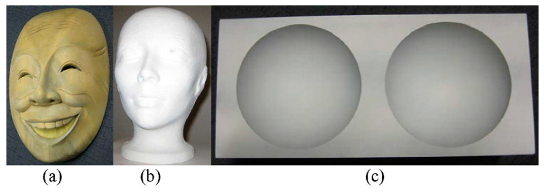
Object surface measurements were performed by projecting onto the object a single binary (black-and-white stripe) grid pattern for each camera-pixel grid pitch used in the calibration, and capturing a single image for each pattern. Phase-shifted moiré patterns (images) were generated by digitally phase shifting a computer-generated grid (of the same pitch as the captured image) overlaid on the captured images, followed by grid removal. Phase-shift analysis was applied to extract the wrapped phase map Φ(x,y) for each grid pitch. Multi-wavelength digital-phase-shifting moiré based on moiré wavelength was performed on a mask with surface discontinuities, two spatially isolated objects (a mask with surface discontinuities and a manikin head) and a double-hemisphere object (Figure 2). The maximum number of phase shifts possible (corresponding to the camera-pixel grid pitches employed) was used for all object measurements: 10 and 12 shifts for the 10- and 12-pixel pitch grids, respectively, used for the mask; 10, 12, and 14 shifts for the 10-, 12-, and 14-pixel pitch grids, respectively, used for the mask with manikin; and 8 and 10 shifts for the 8- and 10-pixel pitch grids, respectively, used for the double hemisphere object. The computation of object height from unwrapped phase for all 3D surface-shape reconstruction used pixelwise moiré-wavelength refinement and pixelwise surface height refinement, described in Section 2.4, using the moiré-wavelength-height relationship determined in Section 2.2.
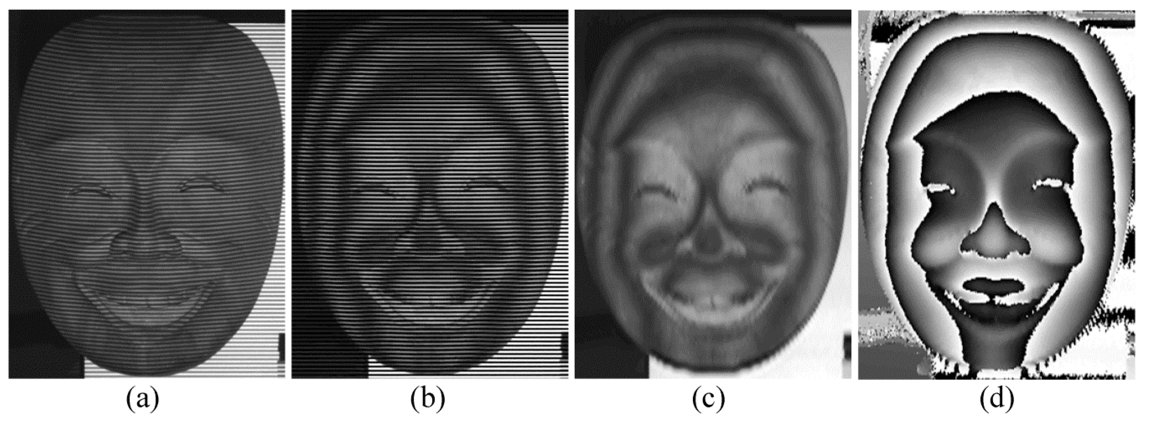
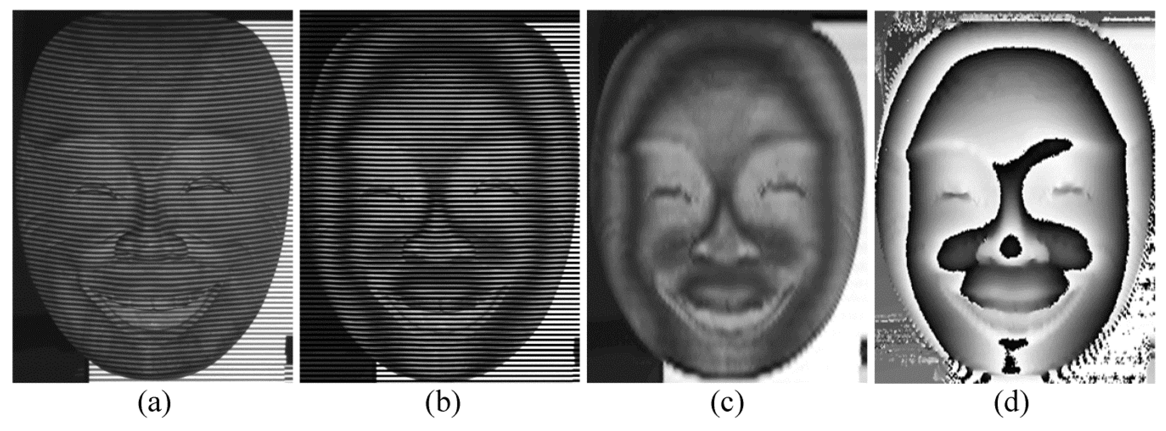
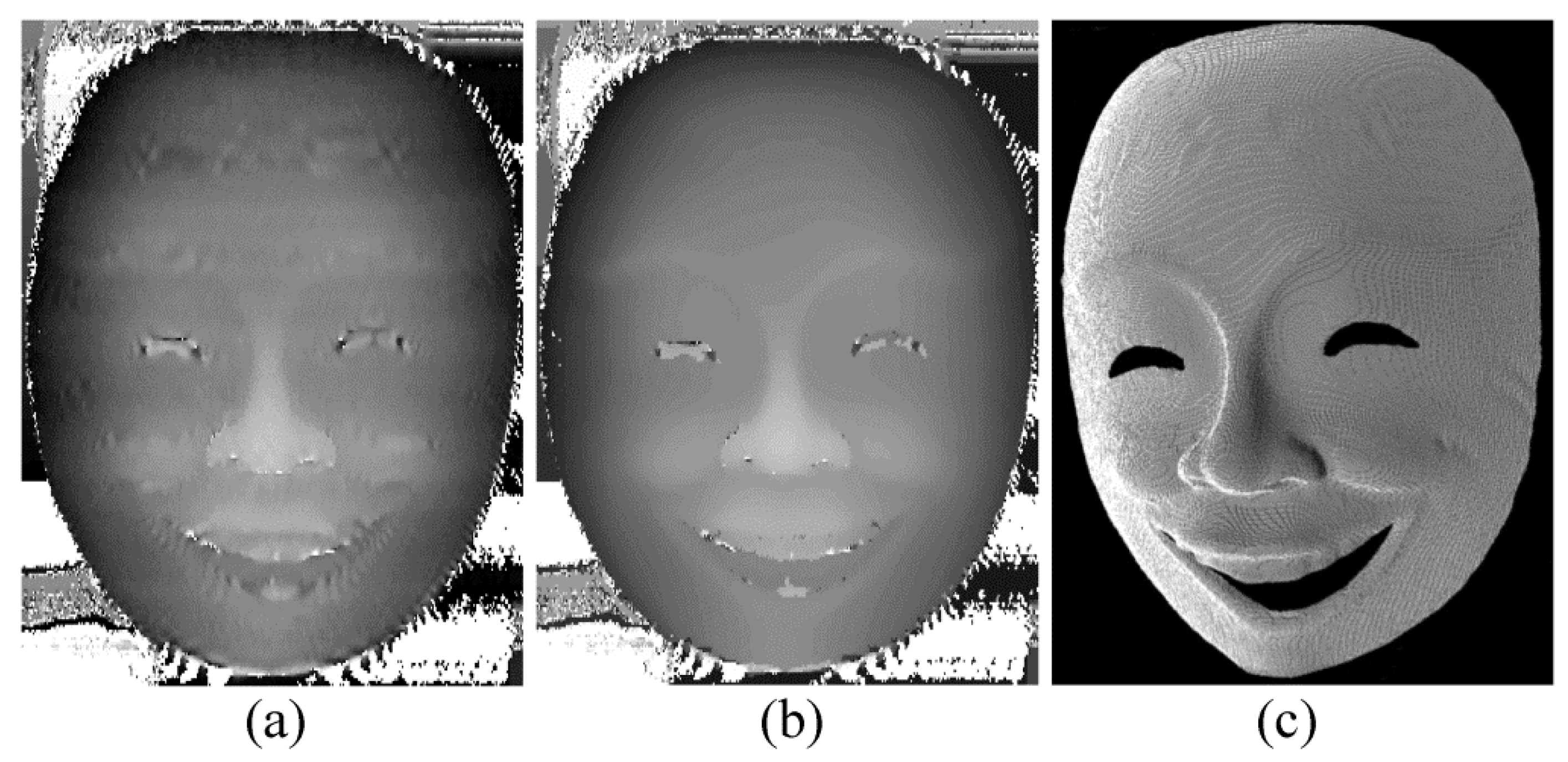
Two-wavelength temporal phase unwrapping was applied to the mask with surface discontinuities by projecting two binary grid patterns with the grid pitches used in the calibration, and capturing a single image for each pattern (10- and 12-pixel grid pitch) (Figure 3a and Figure 4a). For each grid pitch, a moiré pattern with high-frequency grid lines was generated by digital phase-shifting moiré (Figure 3b and Figure 4b), and a pure moiré pattern was extracted by grid removal (Figure 3c and Figure 4c). Two wrapped phase maps Φ 1 and Φ 2 (Figure 3d and Figure 4d) were computed with moiré wavelengths λ 1 and λ 2 (Section 3.2). The extended continuous phase map Φ 12 (Figure 5a) with extended beat wavelength λ 12 = λ 1 λ 2 | λ 1 λ 2 | = 135.567 mm, which covers the entire range of depth, was computed from wrapped phase maps Φ 1 and Φ 2 (Figure 3d and Figure 4d). To minimize the phase error caused by the noise in Φ 12 , Φ 12 with no phase ambiguity was used as a reference to unwrap the phase map Φ 1 with smaller moiré wavelength λ 1 , resulting in the unwrapped phase map φ (Figure 5b). The result demonstrates the ability to obtain an unwrapped phase map with high SNR to perform accurate 3D measurement (Figure 5c) of objects with discontinuities, using only two captured images.
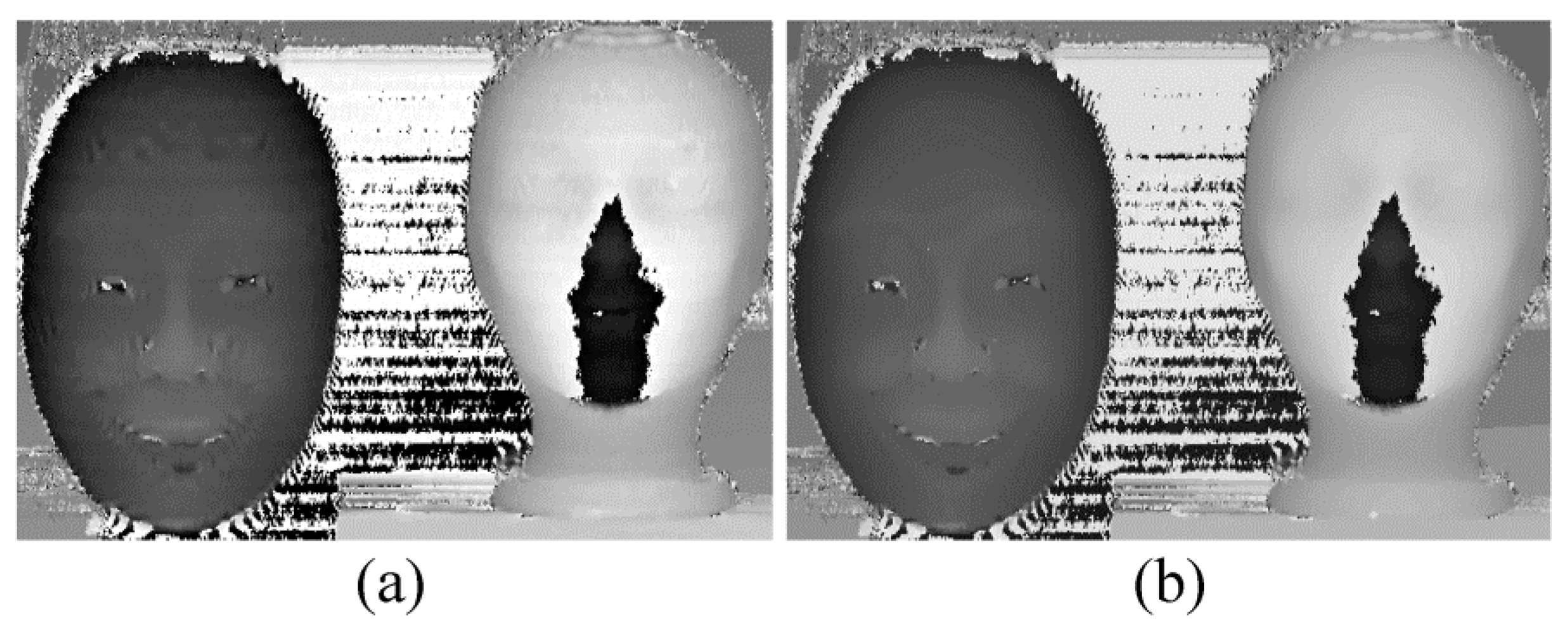
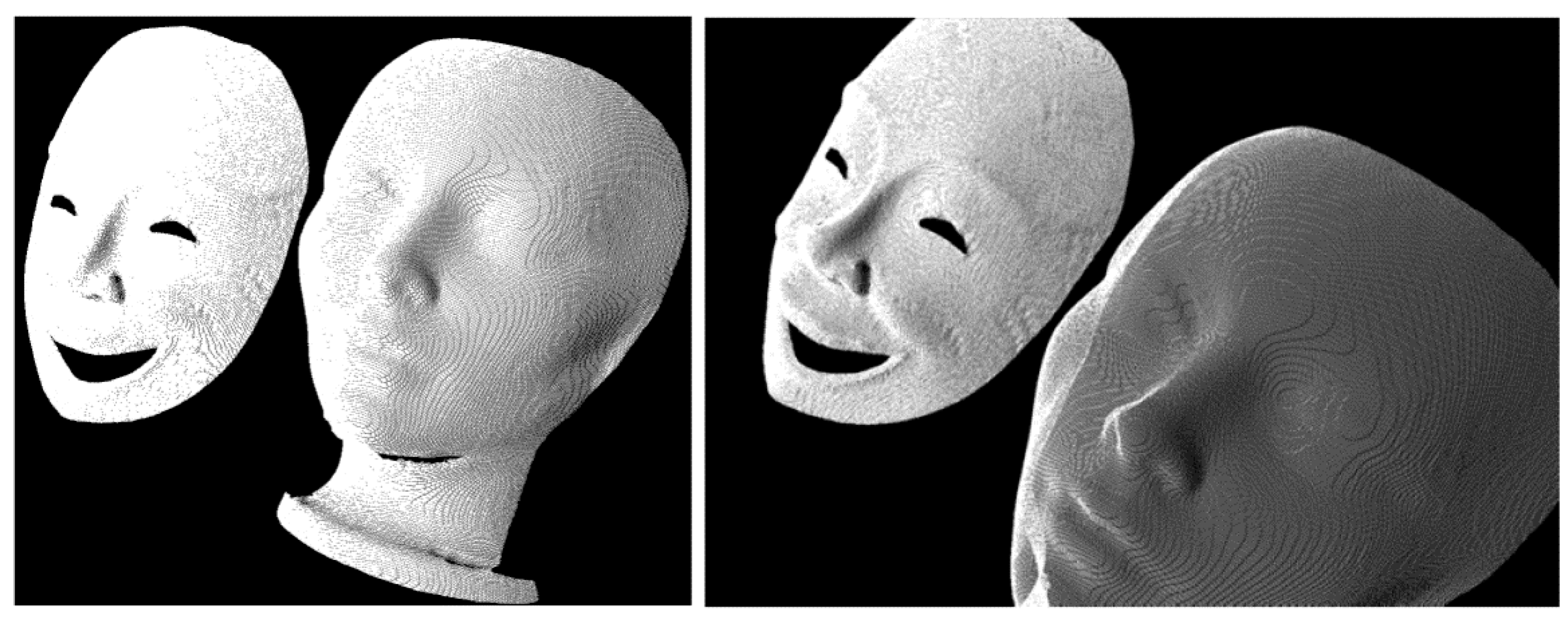
Three-wavelength temporal phase unwrapping was applied to two spatially isolated objects: a mask with surface discontinuities and a manikin head. To handle the greater depth of the manikin compared to the mask, the beat wavelength was increased without sacrificing SNR in the extended phase map, by projection of another pattern with greater grid pitch. Thus, three binary grid patterns with different grid pitches were projected onto the objects and a single image was captured for each pattern (10-, 12-, and 14-pixel grid pitch) (Figure 6a, Figure 7a, and Figure 8a). For each grid pitch, a moiré pattern with high-frequency grid lines was generated by digital phase-shifting moiré (Figure 6b, Figure 7b, and Figure 8b) and a pure moiré pattern was extracted by grid removal (Figure 6c, Figure 7c, and Figure 8c). Three wrapped phase maps Φ 1 , Φ 2 , and Φ 3 (Figure 9a–c) were computed with different moiré wavelengths λ 1 ,   λ 2 , and λ 3 (Section 3.2). The extended phase map Φ 12 (Figure 10a) with extended beat wavelength λ 12 = λ 1 λ 2 | λ 1 λ 2 | = 135.567 mm was computed from phase maps Φ 1 and Φ 2 . To minimize the phase error caused by the noise in Φ 12 , Φ 12 was used as a reference to unwrap the phase map Φ 2 with smaller moiré wavelength λ 2 , to obtain the phase map Φ 12 (Figure 10b) with higher SNR. A second extended phase map Φ 23 (Figure 11a) with extended beat wavelength λ 23 = λ 2 λ 3 | λ 2 λ 3 | = 175.986 mm was computed from phase maps Φ 2 and Φ 3 . To minimize the phase error caused by the noise in Φ 23 , Φ 23 was used as a reference to unwrap the phase map Φ 2 with smaller moiré wavelength λ 2 , to obtain the phase map Φ 23 (Figure 11b) with higher SNR. Note that when the beat moiré wavelength does not cover the full range of depth, phase jumps occur, as seen in the white regions around the manikin head in Figure 10a,b, and in the central black region of the manikin head in Figure 11a,b. When such phase jumps occur, the height cannot be correctly determined. The extended continuous phase map (Figure 12a), which covers the entire range of depth, was then computed from phase maps Φ 12 (Figure 10a) and Φ 23 (Figure 11a), resulting in a noisy phase map (Figure 12a). To improve the measurement, the extended continuous phase map with high SNR Φ 123 (Figure 12b) with extended beat wavelength λ 123 = λ 12 λ 23 | λ 12 λ 23 | = 590.269 mm was calculated from high quality phase maps Φ 12 (Figure 10b) and Φ 23 (Figure 11b). Finally, to calculate a more accurate unwrapped phase map with high SNR, Φ 123 was used as a reference to unwrap Φ 2 with smaller moiré wavelength λ 2 , to obtain the unwrapped phase map φ (Figure 12c), which has high SNR. This high-SNR unwrapped phase map enables accurate 3D measurement of objects with discontinuities and multiple spatially-isolated objects (Figure 13) using only three captured images.
To demonstrate the measurement accuracy of two-image multi-wavelength digital-phase-shifting moiré based on moiré wavelength, a double-hemisphere object, with known hemisphere radii 50.800 ± 0.015 mm and distance between centres 120.000 ± 0.005 mm based on manufacturing specification and precision, was measured. To increase the measurement resolution and accuracy, the calibration was performed by projecting two binary grid patterns with smaller grid pitches (resulting in 8- and 10-pixel grid pitch in the captured images) than for the other objects. The moiré wavelengths were λ 1 = 16.966 mm and λ 2 = 21.035 mm for the 8- and 10-pixel-pitch images, respectively. Two-wavelength temporal phase unwrapping was applied to the double-hemisphere object by projecting two binary grid patterns with the grid pitches used in the calibration, and capturing a single image for each pattern (8- and 10-pixel grid pitch) (Figure 14a and Figure 15a). For each grid pitch, a moiré pattern with high-frequency grid lines was generated by digital phase-shifting moiré (Figure 14b and Figure 15b), and a moiré pattern was extracted by grid removal (Figure 14c and Figure 15c). Two wrapped phase maps Φ 1 and Φ 2 (Figure 16a,b) were computed with moiré wavelengths λ 1 and λ 2 (Section 3.2). The extended continuous phase map Φ 12 (Figure 17a) with extended beat wavelength λ 12 = λ 1 λ 2 | λ 1 λ 2 | = 87.720 mm, which covers the entire range of depth, was computed from wrapped phase maps Φ 1 and Φ 2 (Figure 16a,b). To minimize the phase error caused by the noise in Φ 12 , Φ 12 with no phase ambiguity was used as a reference to unwrap the phase map Φ 1 with smaller moiré wavelength λ 1 , to obtain the unwrapped phase map φ (Figure 17b). Height measurement was performed using Equation (9) and least-squares fitted spheres to the measured 3D point cloud data (Figure 17c) had radii of 50.83 mm and 50.74 mm, and thus errors of 0.03 mm and 0.06 mm, respectively (sphere fitting standard deviations were 0.15 mm and 0.14 mm). The centre-to-centre distance between hemispheres was 119.81 mm, thus with an error of 0.19 mm. A sample cross-section of measured points with the true semicircles is shown in Figure 18, The measured points are close to the true values for most of the surface, except at the edges, which are typically unmeasurable, since the camera and projector optical axes are nearly parallel to the surface.

4. Conclusions

Multi-wavelength digital-phase-shifting moiré was demonstrated using moiré wavelength determined by calibration over the full working depth. The method is the first to compute multiple moiré wavelengths in calibrations over the full working depth and employ them in heterodyne multi-wavelength phase unwrapping in digital moiré. Furthermore, the moiré wavelength calibration determines a moiré-wavelength to height relationship that is used in pixelwise refinement of the moiré wavelength and height during 3D reconstruction. This is the first time that this is applied in multi-wavelength digital moiré. The method has been demonstrated in 3D surface-shape measurement of an object with surface discontinuities and spatially isolated objects.
In the multi-wavelength digital-phase-shifting moiré, the extended noisy phase map is used as a reference to unwrap the phase map with the shorter wavelength, and thus achieve a less noisy and more accurate continuous phase map. Only a single pattern has to be projected and thus single image captured to compute each phase map with different wavelength in order to perform digital-phase-shifting moiré temporal phase unwrapping. Only two captured images are required for two-wavelength phase unwrapping and three captured images for three-wavelength phase unwrapping. The number of projected and captured images required is one third of that for standard heterodyne temporal phase unwrapping by fringe projection. Decreasing the number of required projected and captured images would be advantageous in the image data acquisition process to enable fast measurement of dynamic objects, either moving or deforming. A further advantage for fast image data acquisition for measurement is that the projected grid is binary, which allows fast projection of patterns of different grid periods.

Author Contributions

Conceptualization, F.M. and J.K.; methodology, F.M. and J.K.; software, F.M.; experiments and analysis, F.M.; writing—original draft preparation, F.M.; writing—review and editing, F.M. and J.K.; supervision, J.K.; project administration, J.K.; funding acquisition, J.K.

Funding

This research was funded by the Natural Sciences and Engineering Research Council of Canada and the University of Waterloo.

Conflicts of Interest

The authors declare no conflict of interest.

Appendix A

The intensity distribution IO of the captured image when a binary grid is projected onto an object surface is:
I O ( x , y ) = b 0 + m = 1 b m   cos ( 2 π m p y + ϕ ( x , y ) ) ,
where p is the grid pitch, and (x, y) are the image coordinates. Moiré patterns are generated digitally by first producing a synthetic grid IS with the same pitch as in the captured frame, when the binary grid is projected onto a flat plate.
I S ( x , y ) = a 0 + n = 1 a n   cos ( 2 π n p y ) .
The synthetic grid IS is then superimposed over the captured image of the deformed grid on the object surface, IO, to generate the following image which contains the moiré pattern as well as grid noise and background intensity:
I M = a 0 b 0 + a 0 m = 1 b m cos ( 2 π m p y + 2 π d z ( x , y ) p H ) + b 0 n = 1 a n cos ( 2 π n p y ) +   n = 1 m = 1 a n b m ( cos ( 2 π n p y ) cos ( 2 π m p y + 2 π d z ( x , y ) p H ) ) ,
where H is the camera-projector to object distance, and z is depth. The first term a 0 b 0 is the background intensity, and the second and third terms are the grid noise, composed of the unwanted high-frequency deformed and straight grids, respectively. The fourth term represents the moiré patterns that are encoded with surface-depth (height) information.
A combined stationary-wavelet Fourier transform (SWT-FFT) grid-removal technique [19] can be applied to Equation (A3) to remove the unwanted high-frequency deformed (curved) and straight grid lines (second and third terms, respectively), and thus extract pure moiré patterns. The application of SWT to an image containing grid-noise makes it possible to use a Daubechies wavelet with a low number of vanishing moments to decrease smoothing and distortion in the reconstructed de-noised image. The application of FFT and damping the wavelet coefficients related to grid noise improves SWT in removing highly curved grid lines, without increasing the decomposition level and smearing of the moiré pattern. The combination of SWT and FFT can thus remove both straight and curved grid-noise lines, while minimizing artifacts in the de-noised image, and preserving the moiré pattern without blurring and degradation. Further details of the method are described in Reference [19].

References

  1. Gorthi, S.S.; Rastogi, P. Fringe projection techniques: Whither we are? Opt. Lasers Eng. 2010, 48, 133–140. [Google Scholar] [CrossRef] [Green Version]
  2. Hu, Q.; Harding, K.G. Conversion from phase map to coordinate: Comparison among spatial carrier, Fourier transform, and phase shifting methods. Opt. Lasers Eng. 2007, 45, 342–348. [Google Scholar] [CrossRef]
  3. Song, L.; Chang, Y.; Xi, J.; Guo, Q.; Zhu, X.; Li, X. Phase unwrapping method based on multiple fringe patterns without use of equivalent wavelengths. Opt. Commun. 2015, 355, 213–224. [Google Scholar] [CrossRef] [Green Version]
  4. Zuo, C.; Huang, L.; Zhang, M.; Chen, Q.; Asundi, A. Temporal phase unwrapping algorithms for fringe projection profilometry: A comparative review. Opt. Lasers Eng. 2016, 85, 84–103. [Google Scholar] [CrossRef]
  5. Goldstein, R.M.; Zebker, H.A.; Werner, C.L. Satellite radar interferometry: Two-dimensional phase unwrapping. Radio Sci. 1988, 23, 713–720. [Google Scholar] [CrossRef]
  6. Zappa, E.; Busca, G. Comparison of eight unwrapping algorithms applied to Fourier-transform profilometry. Opt. Lasers Eng. 2008, 46, 106–116. [Google Scholar] [CrossRef]
  7. Creath, K. Step height measurement using two-wavelength phase-shifting interferometry. Appl. Opt. 1987, 26, 2810–2816. [Google Scholar] [CrossRef] [PubMed]
  8. Saldner, H.O.; Huntley, J.M. Temporal phase unwrapping: Application to surface profiling of discontinuous objects. Appl. Opt. 1997, 36, 2770–2775. [Google Scholar] [CrossRef] [PubMed]
  9. Reich, C.; Ritter, R.; Thesing, J. White light heterodyne principle for 3D-measurement. In Proceedings of the SPIE 3100, Sensors, Sensor Systems, and Sensor Data Processing, Lasers and Optics in Manufacturing III, Munich, Germany, 16–20 June 1997; pp. 236–244. [Google Scholar]
  10. Cheng, Y.Y.; Wyant, J.C. Two-wavelength phase shifting interferometry. Appl. Opt. 1984, 23, 4539–4543. [Google Scholar] [CrossRef] [PubMed]
  11. Zhang, H.; Chen, W.; Tan, Y. Phase-unwrapping algorithm for the measurement of three-dimensional object shapes. Appl. Opt. 1994, 33, 4497–4500. [Google Scholar]
  12. Cheng, Y.Y.; Wyant, J.C. Multiple-wavelength phase-shifting interferometry. Appl. Opt. 1985, 24, 804–807. [Google Scholar] [CrossRef] [PubMed]
  13. Song, L.; Dong, X.; Xi, J.; Yu, Y.; Yang, C. A new phase unwrapping algorithm based on three wavelength phase shift profilometry method. Opt. Lasers Technol. 2013, 45, 319–329. [Google Scholar] [CrossRef]
  14. Geng, L.; Liu, Y.; Xiao, Z.; Wu, J.; Zhang, Y.; Yuan, F.; Yang, Z.; Gan, P.; Su, J.; Ye, K. Phase unwrapping method based on heterodyne three frequency non-equal step phase shift. In Proceedings of the International Conference on Image and Graphics 2015, Part III, Lecture Notes in Computer Science 9219, Tianjin, China, 13–16 August 2015; pp. 68–79. [Google Scholar]
  15. Towers, C.E.; Towers, D.P.; Jones, J.D.C. Optimum frequency selection in multi-frequency interferometry. Opt. Lett. 2003, 28, 887–889. [Google Scholar] [CrossRef] [PubMed]
  16. Towers, C.E.; Towers, D.P.; Jones, J.D.C. Absolute fringe order calculation using optimised multi- frequency selection in full-field profilometry. Opt. Lasers Eng. 2005, 43, 788–800. [Google Scholar] [CrossRef]
  17. Mohammadi, F.; Kofman, J. Single-frame digital phase-shifting 3D shape measurement using pixel-wise moiré-wavelength refinement. Opt. Lasers Eng. 2016, 78, 196–204. [Google Scholar] [CrossRef]
  18. Ryu, W.J.; Kang, Y.J.; Baik, S.H.; Kang, S.J. A study on the 3-D measurement by using digital projection moiré method. Optik 2008, 119, 453–458. [Google Scholar] [CrossRef]
  19. Mohammadi, F.; Kofman, J. Improved grid-noise removal in single-frame digital moiré 3D shape measurement. Opt. Lasers Eng. 2016, 86, 143–155. [Google Scholar] [CrossRef]
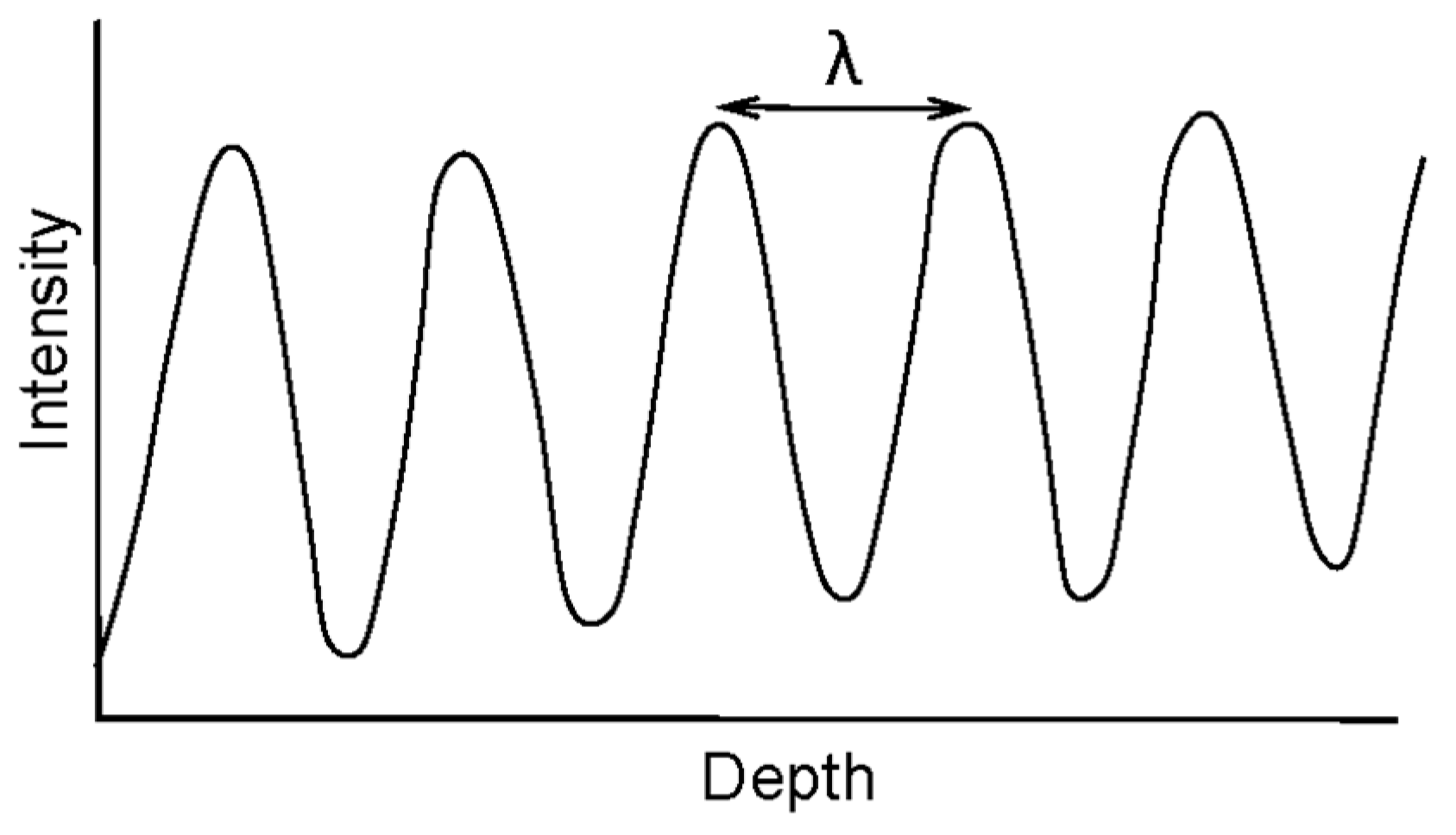
Figure 1. Moiré wavelength λ shown as the distance between two consecutive fringe-plane intensity maxima corresponding to bright fringes on a flat plate, for a single image pixel. The wavelength varies over depth (across different peak pairs).
Applsci 09 01917 g001
Figure 2. Objects used in surface measurement experiments: (a) Mask, (b) manikin head, and (c) double-hemisphere.
Applsci 09 01917 g002
Figure 3. Wrapped phase map computation: (a) Original captured image of the mask with binary grid of 10-pixel pitch, (b) generated image with moiré pattern and high-frequency grid lines, (c) moiré pattern after grid removal, and (d) wrapped phase map Φ1.
Applsci 09 01917 g003
Figure 4. Wrapped phase map computation: (a) Original captured image of the mask with binary grid of 12-pixel pitch, (b) generated image with moiré pattern and high-frequency grid lines, (c) moiré pattern after grid removal, and (d) wrapped phase map Φ2.
Applsci 09 01917 g004
Figure 5. (a) Extended continuous phase map Φ12 with extended beat wavelength λ 12 , (b) unwrapped phase map φ, and (c) point cloud representation of measured points of mask.
Applsci 09 01917 g005
Figure 6. Moiré pattern generation: (a) Original captured image of objects with binary grid of 10-pixel pitch, (b) generated image with moiré pattern and high-frequency grid lines, and (c) moiré pattern after grid removal.
Applsci 09 01917 g006
Figure 7. Moiré pattern generation: (a) Original captured image of objects with binary grid of 12-pixel pitch, (b) generated image with moiré pattern and high-frequency grid lines, and (c) moiré pattern after grid removal.
Applsci 09 01917 g007
Figure 8. Moiré pattern generation: (a) Original captured image of objects with binary grid of 14-pixel pitch, (b) generated image with moiré pattern and high-frequency grid lines, and (c) moiré pattern after grid removal.
Applsci 09 01917 g008
Figure 9. Wrapped phase maps: (a) Φ1, (b) Φ2, and (c) Φ3.
Applsci 09 01917 g009
Figure 10. Extended phase maps: (a) Φ12 with extended beat wavelength λ 12 , and (b) Φ12 with higher SNR.
Applsci 09 01917 g010
Figure 11. Extended phase maps: (a) Φ23 with extended beat wavelength λ 23 , and (b) Φ23 with higher SNR.
Applsci 09 01917 g011
Figure 12. Extended continuous phase maps: (a) Extended continuous phase map calculated from Φ12 and Φ23, (b) Φ123 with high SNR and with extended beat wavelength λ 123 calculated from Φ12 and Φ23, and (c) unwrapped phase map φ.
Applsci 09 01917 g012
Figure 13. Point cloud representations of measured points of spatially isolated objects, mask, and manikin head.
Applsci 09 01917 g013
Figure 14. Moiré pattern generation: (a) Original captured image of double-hemisphere object with binary grid of 8-pixel pitch, (b) generated image with moiré pattern and high-frequency grid lines, and (c) moiré pattern after grid removal.
Applsci 09 01917 g014
Figure 15. Moiré pattern generation: (a) Original captured image of double-hemisphere object with binary grid of 10-pixel pitch, (b) generated image with moiré pattern and high-frequency grid lines, and (c) moiré pattern after grid removal.
Applsci 09 01917 g015
Figure 16. Wrapped phase maps: (a) Φ1, (b) Φ2.
Applsci 09 01917 g016
Figure 17. (a) Extended continuous phase map Φ12 with extended beat wavelength λ 12 , (b) unwrapped phase map φ, and (c) point cloud representation of double-hemisphere object.
Applsci 09 01917 g017
Figure 18. Sample cross-section of measured points of double-hemisphere object and true semicircles.
Applsci 09 01917 g018
Table 1. Calculated moiré wavelengths for different camera-pixel grid pitches (minimum, maximum, and at mid-calibration-depth).
Grid Pitch
(pixels)
λ Min   ( mm ) λ Max
(mm)
λ   Mid - Calibration   Depth   ( mm )
815.8819.08       16.966
1019.6224.09  21.850 21.035
1223.7828.31  26.048
1427.9333.22  30.573