
Comparative Analysis of Stress and Deformation between One-Fenced and Three-Fenced Dental Implants Using Finite Element Analysis


 ,
, 
Abstract
:1. Introduction
2. Materials and Methods
2.1. Selection of the Implant Material
2.2. Geometry
2.3. Health Condition of the Patient
2.4. Standard of the Bone
2.5. Design and FEA
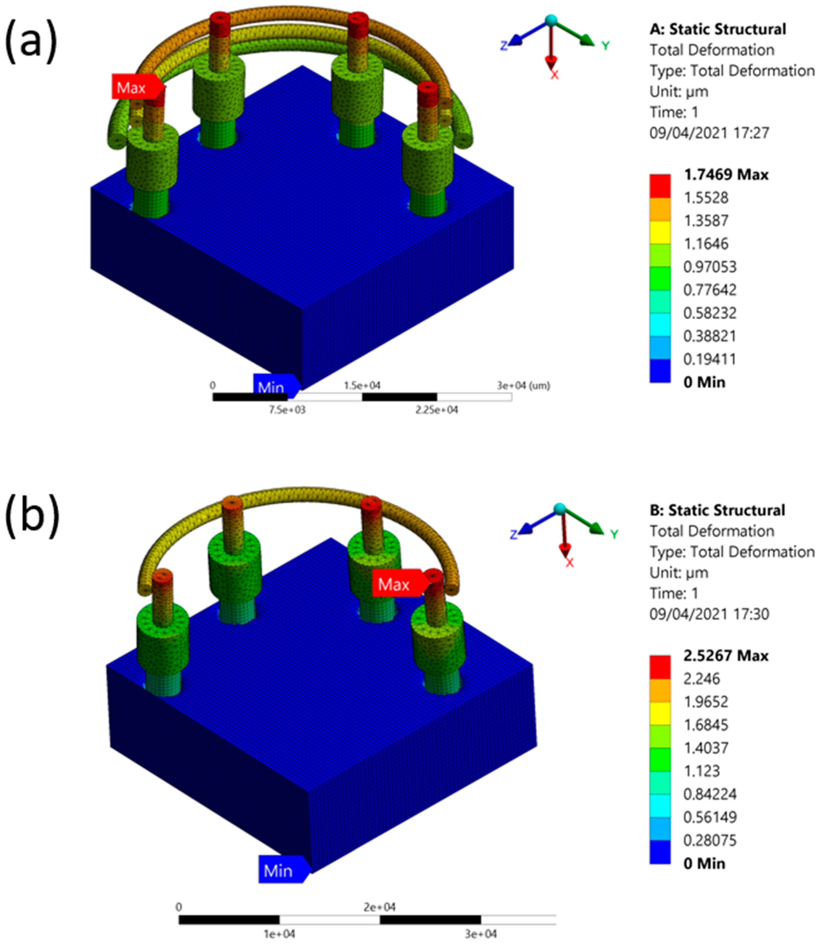
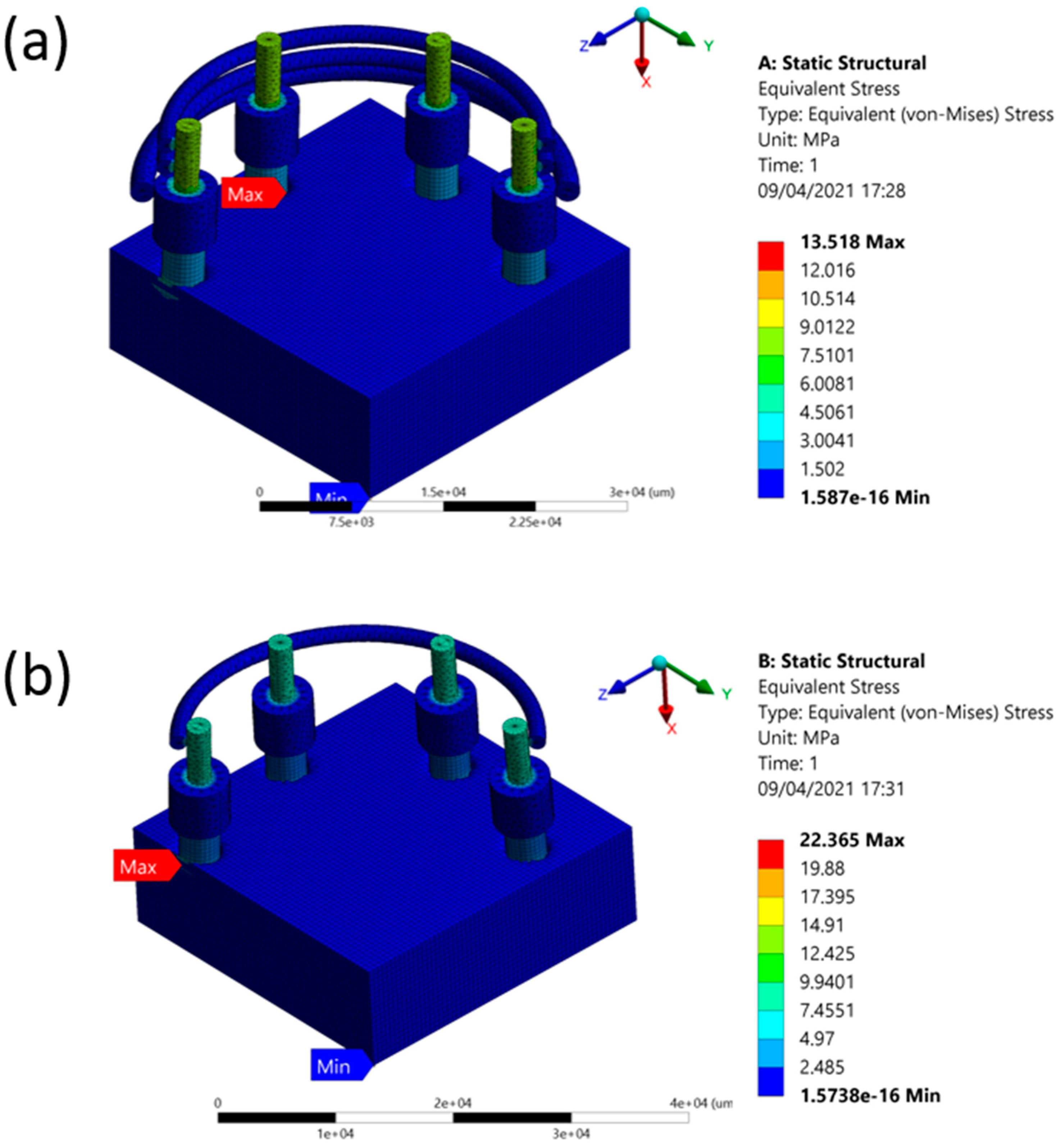
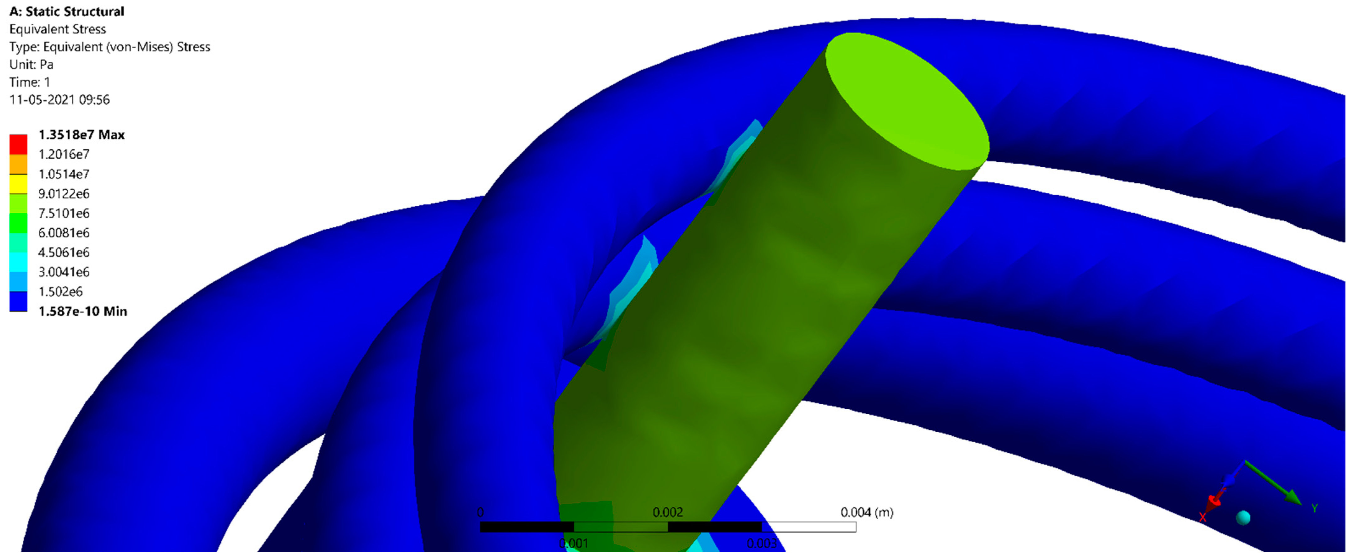
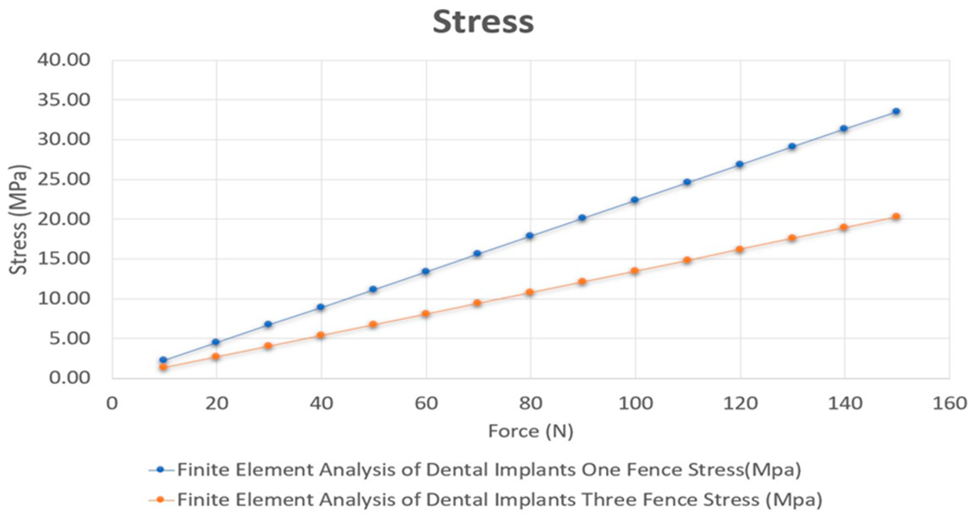
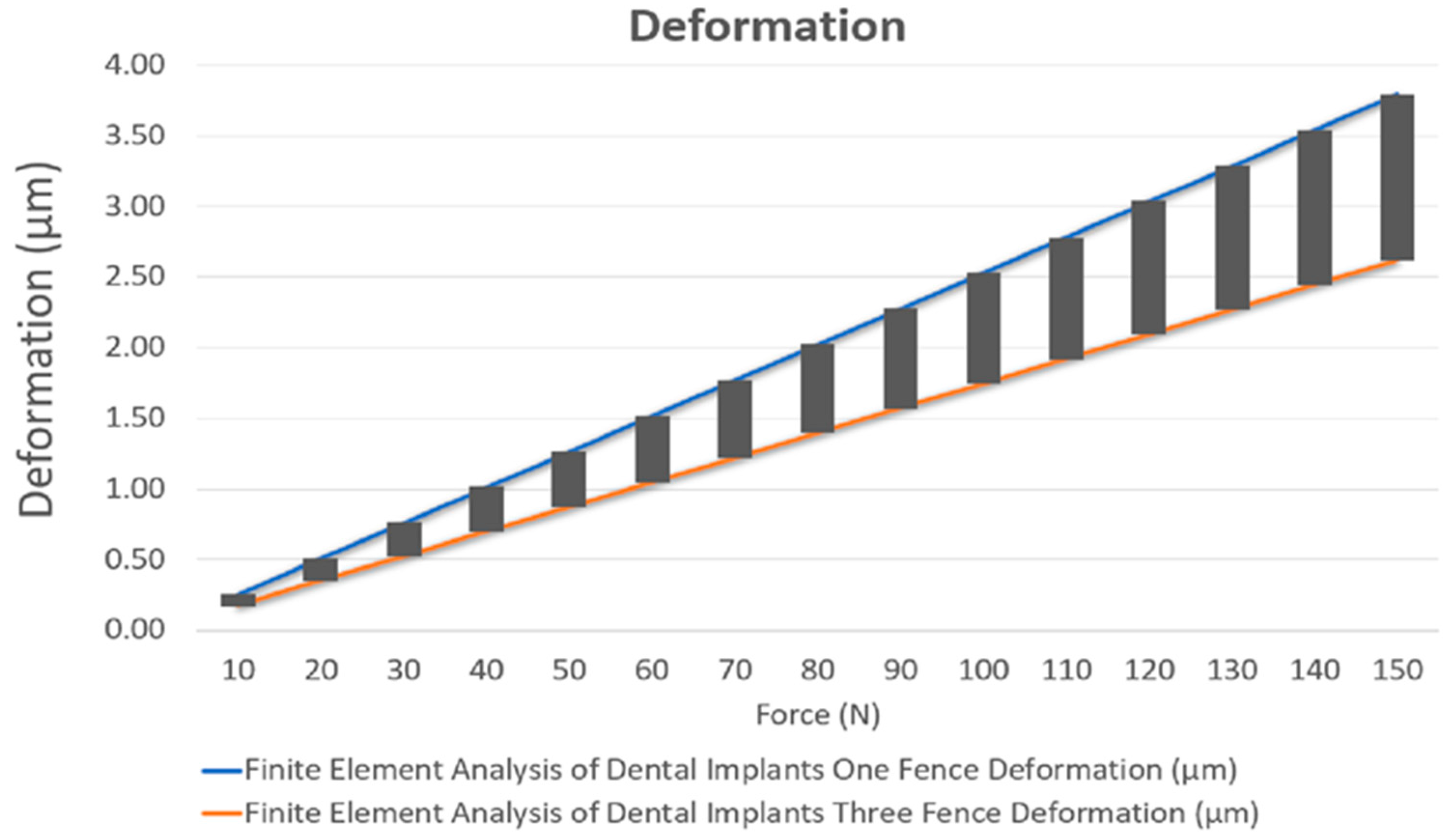
3. Results
4. Discussion
5. Conclusions
Supplementary Materials
Author Contributions
Funding
Institutional Review Board Statement
Informed Consent Statement
Data Availability Statement
Conflicts of Interest
References
- Zienkiewicz, O.C. The Finite Element Methods in Engineering Science; McGraw-Hill: New York, NY, USA, 1971. [Google Scholar]
- Parithimarkalaignan, S.; Padmanabhan, T. Osseointegration: An update. J. Indian Prosthodont. Soc. 2013, 13, 2–6. [Google Scholar] [CrossRef]
- Chun, H.J.; Cheong, S.Y.; Han, J.H.; Heo, S.J.; Chung, J.P.; Rhyu, I.C.; Choi, Y.C.; Baik, H.K.; Ku, Y.; Kim, M.H. Evaluation of design parameters of osseointegrated dental implants using finite element analysis. J. Oral Rehabil. 2002, 29, 565–574. [Google Scholar] [CrossRef] [PubMed]
- Soto-Peñaloza, D.; Zaragozí-Alonso, R.; Peñarrocha-Diago, M.; Peñarrocha-Diago, M. The all-on-four treatment concept: Systematic review. J. Clin. Exp. Dent. 2017, 9, e474. [Google Scholar] [CrossRef] [PubMed] [Green Version]
- Ayna, M.; Gülses, A.; Acil, Y. A comparative study on 7-year results of “All-on-Four™” immediate-function concept for completely edentulous mandibles: Metal-ceramic vs. bar-retained superstructures. Odontology 2018, 106, 73–82. [Google Scholar] [CrossRef] [PubMed]
- Maló, P.; Rangert, B.; Nobre, M. “All-on-Four” immediate-function concept with Brånemark System® implants for completely edentulous mandibles: A retrospective clinical study. Clin. Implant.Dent. Relat. Res. 2003, 5, 2–9. [Google Scholar] [CrossRef]
- Maló, P.; Friberg, B.; Polizzi, G.; Gualini, F.; Vighagen, T.; Rangert, B. Immediate and early function of Brånemark System® implants placed in the esthetic zone: A 1-year prospective clinical multicenter study. Clin. Implant. Dent. Relat. Res. 2003, 5, 37–46. [Google Scholar] [CrossRef] [PubMed]
- Jemt, T.; Lekholm, U.; Adell, R. Osseointegreated Implants in the Treatment of Partially Edentulous Patients: A Preliminary Study on 876 Consecutively Placed Fixtures. Int. J. Oral Maxillofac. Implant. 1989, 4, 44–58. [Google Scholar]
- Sagara, M.; Akagawa, Y.; Nikai, H.; Tsuru, H. The effects of early occlusal loading on one-stage titanium alloy implants in beagle dogs: A pilot study. J. Prosthet. Dent. 1993, 69, 281–288. [Google Scholar] [CrossRef]
- Quirynen, M.; Naert, I.; Van Steenberghe, D. Fixture design and overload influence marginal bone loss and future success in the Brånemark® system. Clin. Oral Implant. Res. 1992, 3, 104–111. [Google Scholar] [CrossRef] [PubMed]
- Marcián, P.; Wolff, J.; Horáˇcková, L.; Kaiser, J.; Zikmund, T.; Borák, L. Micro finite element analysis of dental implants under different loading conditions. Comput. Biol. Med. 2018, 96, 157–165. [Google Scholar] [CrossRef]
- Nimbalkar, S.; Dhatrak, P.; Gherde, C.; Joshi, S. A review article on factors affecting bone loss in dental implants. Mater. Today Proc. 2021, 43, 970–976. [Google Scholar] [CrossRef]
- Vogel, D.; Wehmeyer, M.; Kebbach, M.; Heyer, H.; Bader, R. Stress and strain distribution in femoral heads for hip resurfacing arthroplasty with different materials: A finite element analysis. J. Mech. Behav. Biomed. Mater. 2021, 113, 104115. [Google Scholar] [CrossRef] [PubMed]
- Jayakumar, N.; Senthilkumar, G.; Vigneshwaran, S.; Kumar, K.A. Comparison of stress distribution on dental implant with different abutment types. Mater. Today Proc. 2021, 45, 7970–7979. [Google Scholar] [CrossRef]
- Li, J.; Jansen, J.A.; Walboomers, X.F.; van den Beucken, J.J. Mechanical aspects of dental implants and osseointegration: A narrative review. J. Mech. Behav. Biomed. Mater. 2020, 103, 103574. [Google Scholar] [CrossRef] [PubMed]
- Tada, S.; Stegaroiu, R.; Kitamura, E.; Miyakawa, O.; Kusakari, H. Influence of implant design and bone quality on stress/strain distribution in bone around implants: A 3-dimensional finite element analysis. Int. J. Oral Maxillofac. Implant. 2003, 18, 357–368. [Google Scholar]
- Baggi, L.; Cappelloni, I.; Di Girolamo, M.; Maceri, F.; Vairo, G. The influence of implant diameter and length on stress distribution of osseointegrated implants related to crestal bone geometry: A three-dimensional finite element analysis. J. Prosthet. Dent. 2008, 100, 422–431. [Google Scholar] [CrossRef] [Green Version]
- Degidi, M.; Gehrke, P.; Spanel, A.; Piattelli, A. Syncrystallization: A technique for temporization of immediately loaded implants with metal-reinforced acrylic resin restorations. Clin. Implant Dent. Rela. Res. 2006, 8, 123–134. [Google Scholar] [CrossRef] [PubMed]
- Sun, Y.H.; Shih, Y.H.; Li, C.H.; Fang, C.Y. Rehabilitation of occlusion on a severe atrophic mandible by four implants-supported fixed conometric denture after bilateral inferior alveolar nerve repositioning. J. Dent. Sci. 2020, 16, 780. [Google Scholar] [CrossRef]
- Seth, S.; Kalra, P. Effect of dental implant parameters on stress distribution at bone-implant interface. Inter. J. Sci. Res. 2013, 2, 121–124. [Google Scholar]
- Schmalz, G.; Arenholt-Bindslev, D. Biocompatibility of Dental Materials; Springer: Berlin/Heidelberg, Germany, 1999; Volume 1. [Google Scholar]
- Elias, C.N. Factors affecting the success of dental implants. In Implant Dentistry: A Rapidly Evolving Practice; InTech: Rijeka, Croatia, 2011; pp. 319–364. [Google Scholar]
- Gaviria, L.; Salcido, J.P.; Guda, T.; Ong, J.L. Current trends in dental implants. J. Korean Assoc. Oral Maxillofac. Surg. 2014, 40, 50–60. [Google Scholar] [CrossRef]
- Sullivan, R.M. Implant dentistry and the concept of osseointegration: A historical perspective. J. Calif. Dent. Assoc. 2001, 29, 737–745. [Google Scholar]
- Sykaras, N.; Iacopino, A.M.; Marker, V.A.; Triplett, R.G.; Woody, R.D. Implant materials, designs, and surface topographies: Their effect on osseointegration. A literature review. Int. J. Oral Maxillofac. Implant. 2000, 15, 675–690. [Google Scholar]
- Hodosh, M.; Shklar, G.; Povar, M. The porous vitreous carbon/polymethacrylate tooth implant: Preliminary studies. J. Prosthet. Dent. 1974, 32, 326–334. [Google Scholar] [CrossRef]
- Rahmitasari, F.; Ishida, Y.; Kurahashi, K.; Matsuda, T.; Watanabe, M.; Ichikawa, T. PEEK with reinforced materials and modifications for dental implant applications. Dent. J. 2017, 5, 35. [Google Scholar] [CrossRef] [Green Version]
- Najeeb, S.; Zafar, M.S.; Khurshid, Z.; Siddiqui, F. Applications of polyetheretherketone (PEEK) in oral implantology and prosthodontics. J. Prosthodont. Res. 2016, 60, 12–19. [Google Scholar] [CrossRef]
- Hulbert, S.; Matthews, J.; Klawitter, J.; Sauer, B.; Leonard, R. Effect of stress on tissue ingrowth into porous aluminum oxide. J. Biomed. Mater. Res. 1974, 8, 85–97. [Google Scholar] [CrossRef] [PubMed]
- Dubruille, J.H.; Viguier, E.; Le Naour, G.; Dubruille, M.T.; Auriol, M.; Le Charpentier, Y. Evaluation of combinations of titanium, zirconia, and alumina implants with 2 bone fillers in the dog. Int. J. Oral Maxillofac. Implant. 1999, 14, 271–277. [Google Scholar]
- Afrashtehfar, K.I.; Del Fabbro, M. Clinical performance of zirconia implants: A meta-review. J. Prosthet. Dent. 2020, 123, 419–426. [Google Scholar] [CrossRef] [PubMed]
- Bosshardt, D.D.; Chappuis, V.; Buser, D. Osseointegration of titanium, titanium alloy and zirconia dental implants: Current knowledge and open questions. Periodontology 2000 2017, 73, 22–40. [Google Scholar] [CrossRef]
- Elias, C.; Lima, J.; Valiev, R.; Meyers, M. Biomedical applications of titanium and its alloys. Jom 2008, 60, 46–49. [Google Scholar] [CrossRef]
- Mijiritsky, E.; Mazor, Z.; Lorean, A.; Levin, L. Implant diameter and length influence on survival: Interim results during the first 2 years of function of implants by a single manufacturer. Implant. Dent. 2013, 22, 394–398. [Google Scholar] [CrossRef] [PubMed] [Green Version]
- Lee, J.H.; Frias, V.; Lee, K.W.; Wright, R.F. Effect of implant size and shape on implant success rates: A literature review. J. Prosthet. Dent. 2005, 94, 377–381. [Google Scholar] [CrossRef]
- Searson, L.J.; Gough, M.; Hemmings, K. Implantology in General Dental Practice; Quintessence Publishing Company Limited: Tokyo, Japan, 2019; Volume 4. [Google Scholar]
- Mandhane, S.S.; More, A.P. A review: Evaluation of design parameters of dental implant abutment. Int. J. Emerg. Sci. Eng. 2014, 2, 64–67. [Google Scholar]
- Shemtov-Yona, K.; Rittel, D.; Levin, L.; Machtei, E.E. Effect of Dental Implant Diameter on Fatigue Performance. Part I: Mechanical Behavior. Clin. Implant. Dent. Relat. Res. 2014, 16, 172–177. [Google Scholar] [PubMed]
- Ivanoff, C.J.; Sennerby, L.; Johansson, C.; Rangert, B.; Lekholm, U. Influence of implant diameters on the integration of screw implants: An experimental study in rabbits. Int. J. Oral Maxillofac. Surg. 1997, 26, 141–148. [Google Scholar] [CrossRef]
- Scully, C.; Hobkirk, J.; Dios, P.D. Dental endosseous implants in the medically compromised patient 1. J. Oral Rehabil. 2007, 34, 590–599. [Google Scholar] [CrossRef]
- Paquette, D.W.; Brodala, N.; Williams, R.C. Risk factors for endosseous dental implant failure. Dent. Clin. 2006, 50, 361–374. [Google Scholar] [CrossRef]
- Diz, P.; Scully, C.; Sanz, M. Dental implants in the medically compromised patient. J. Dent. 2013, 41, 195–206. [Google Scholar] [CrossRef]
- Gulsahi, A. Bone Quality Assessment for Dental Implants; InTech: Rijeka, Croatia, 2011; pp. 437–452. [Google Scholar]
- Marquezan, M.; Osório, A.; Sant’Anna, E.; Souza, M.M.; Maia, L. Does bone mineral density influence the primary stability of dental implants? A systematic review. Clin. Oral Implant. Res. 2012, 23, 767–774. [Google Scholar] [CrossRef]
- Lekholm, U. Patient selection and preparation. In Tissue-Integrated Prostheses Osseointegration in Clinical Dentistry; Plastic and Reconstructive Surgery; Lippincott Williams & Wilkins: Philadelphia, PA, USA, 1985; pp. 199–209. [Google Scholar]
- Watanabe, Y. Age Changes in Oral Function. In Reference Module in Biomedical Sciences; Elsevier: Amsterdam, The Netherlands, 2014. [Google Scholar] [CrossRef]
- Saini, H.; Ackland, D.C.; Gong, L.; Leo, K.; Cheng; Röhrle, O. Occlusal load modelling significantly impacts the predicted tooth stress response during biting: A simulation study. Comput. Methods Biomech. Biomed. Eng. 2020, 23, 261–270. [Google Scholar] [CrossRef]
- Cosola, S.; Toti, P.; Babetto, E.; Covani, U.; Peñarrocha-Diago, M.; Peñarrocha-Oltra, D. In-vitro fatigue and fracture performance of three different ferrulized implant connections used in fixed prosthesis. J. Dent. Sci. 2021, 16, 397–403. [Google Scholar] [CrossRef] [PubMed]
- Cosola, S.; Toti, P.; Babetto, E.; Covani, U.; Peñarrocha-Diago, M.; Peñarrocha-Oltra, D. In-Vitro Investigation of Fatigue and Fracture Behavior of Transmucosal versus Submerged Bone Level Implants Used in Fixed Prosthesis. Appl. Sci. 2021, 11, 6186. [Google Scholar] [CrossRef]
- Figueiredo, R.B.; Barbosa, E.R.d.C.; Zhao, X.; Yang, X.; Liu, X.; Cetlin, P.R.; Langdon, T.G. Improving the fatigue behavior of dental implants through processing commercial purity titanium by equal-channel angular pressing. Mater. Sci. Eng. A 2014, 619, 312–318. [Google Scholar] [CrossRef]

| Material | Density (g/cm³) | Young’s Modulus (MPa) | Poisson’s Ratio | Compressive Yield Strength (MPa) |
|---|---|---|---|---|
| Titanium Alloy | 4.620 | 96,000 | 0.36 | 930 |
| Cancellous Bone | 2.08 | 71,000 | 0.3 | 280 |
| Cortical Bone | 1.2 | 2000 | 0.3 | 112 |
| Object | Minimum (µm) | Maximum (µm) | Average (µm) |
|---|---|---|---|
| One Fence | 0 | 2.5267 | 0.21521 |
| Three Fences | 0 | 1.7469 | 0.22412 |
| Object | Minimum (MPa) | Maximum (MPa) | Average (MPa) |
|---|---|---|---|
| One Fence | 1.5738 × 10⁻¹⁶ | 22.356 | 0.47612 |
| Three Fences | 1.587 × 10⁻¹⁶ | 13.518 | 0.46134 |
| Object | Minimum (µm) | Maximum (µm) | Average (µm) |
|---|---|---|---|
| One Fence | 0 | 171.95 | 9.5416 |
| Three Fences | 0 | 169.04 | 11.36 |
| Object | Minimum (MPa) | Maximum (MPa) | Average (MPa) |
|---|---|---|---|
| One Fence | 4.5963 × 10⁻¹⁸ | 320.7 | 3.0263 |
| Three Fences | 1.1637 × 10⁻¹⁶ | 245.34 | 3.1472 |
| Object | Minimum (µm) | Maximum (µm) | Average (µm) |
|---|---|---|---|
| One Fence | 0 | 6.8344 | 0.42715 |
| Three Fences | 0 | 5.366 | 0.42004 |
| Object | Minimum (MPa) | Maximum (MPa) | Average (MPa) |
|---|---|---|---|
| One Fence | 3.2548 × 10⁻¹⁶ | 64.467 | 0.94536 |
| Three Fences | 3.257 × 10⁻¹⁶ | 40.963 | 0.925 |
Publisher’s Note: MDPI stays neutral with regard to jurisdictional claims in published maps and institutional affiliations. |
© 2021 by the authors. Licensee MDPI, Basel, Switzerland. This article is an open access article distributed under the terms and conditions of the Creative Commons Attribution (CC BY) license (https://creativecommons.org/licenses/by/4.0/).
Share and Cite
Lee, C.-H.; Mukundan, A.; Chang, S.-C.; Wang, Y.-L.; Lu, S.-H.; Huang, Y.-C.; Wang, H.-C. Comparative Analysis of Stress and Deformation between One-Fenced and Three-Fenced Dental Implants Using Finite Element Analysis. J. Clin. Med. 2021, 10, 3986. https://doi.org/10.3390/jcm10173986
Lee C-H, Mukundan A, Chang S-C, Wang Y-L, Lu S-H, Huang Y-C, Wang H-C. Comparative Analysis of Stress and Deformation between One-Fenced and Three-Fenced Dental Implants Using Finite Element Analysis. Journal of Clinical Medicine. 2021; 10(17):3986. https://doi.org/10.3390/jcm10173986
Chicago/Turabian StyleLee, Chia-Hsuan, Arvind Mukundan, Szu-Chien Chang, Yin-Lai Wang, Shu-Hao Lu, Yu-Cheng Huang, and Hsiang-Chen Wang. 2021. "Comparative Analysis of Stress and Deformation between One-Fenced and Three-Fenced Dental Implants Using Finite Element Analysis" Journal of Clinical Medicine 10, no. 17: 3986. https://doi.org/10.3390/jcm10173986