
Three-Dimensionally Printed Elastic Cardiovascular Phantoms for Carotid Angioplasty Training and Personalized Healthcare

 ,
,  , , , , and
Abstract
1. Introduction
2. Materials and Methods
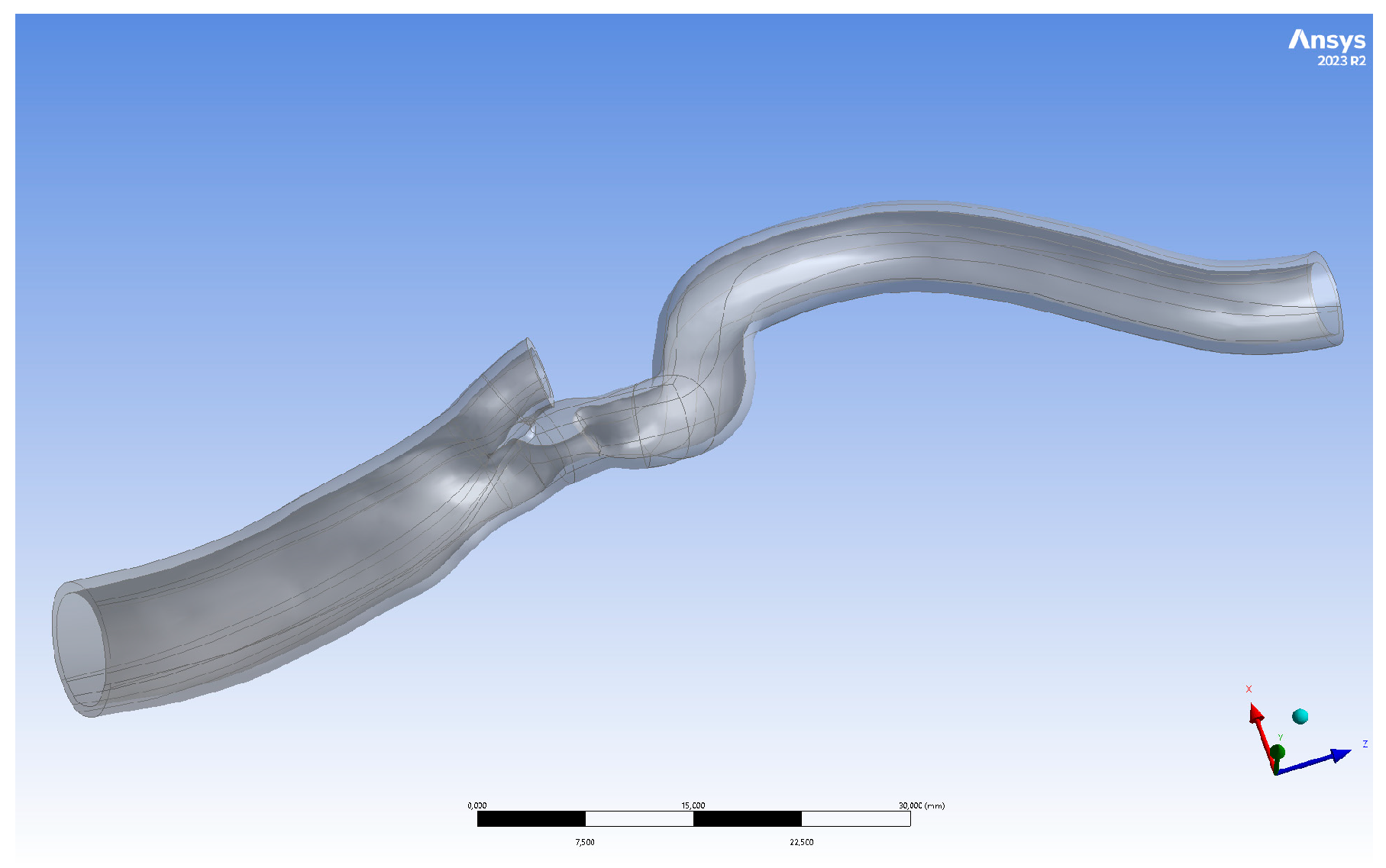
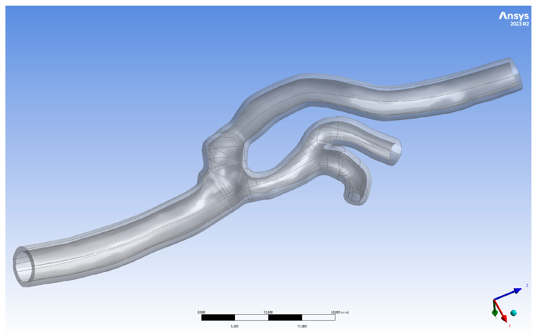
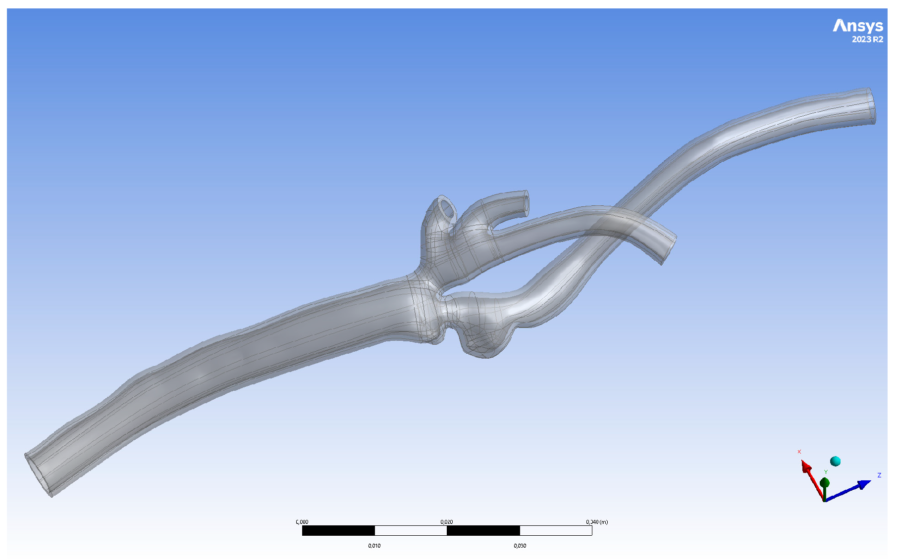
2.1. Geometry Preparation
2.2. Three-Dimensional Printing
2.3. Mechanical and Optical Parameters Measurements
2.4. Experimental Setup
3. Results
3.1. Mechanical and Optical Parameters Results
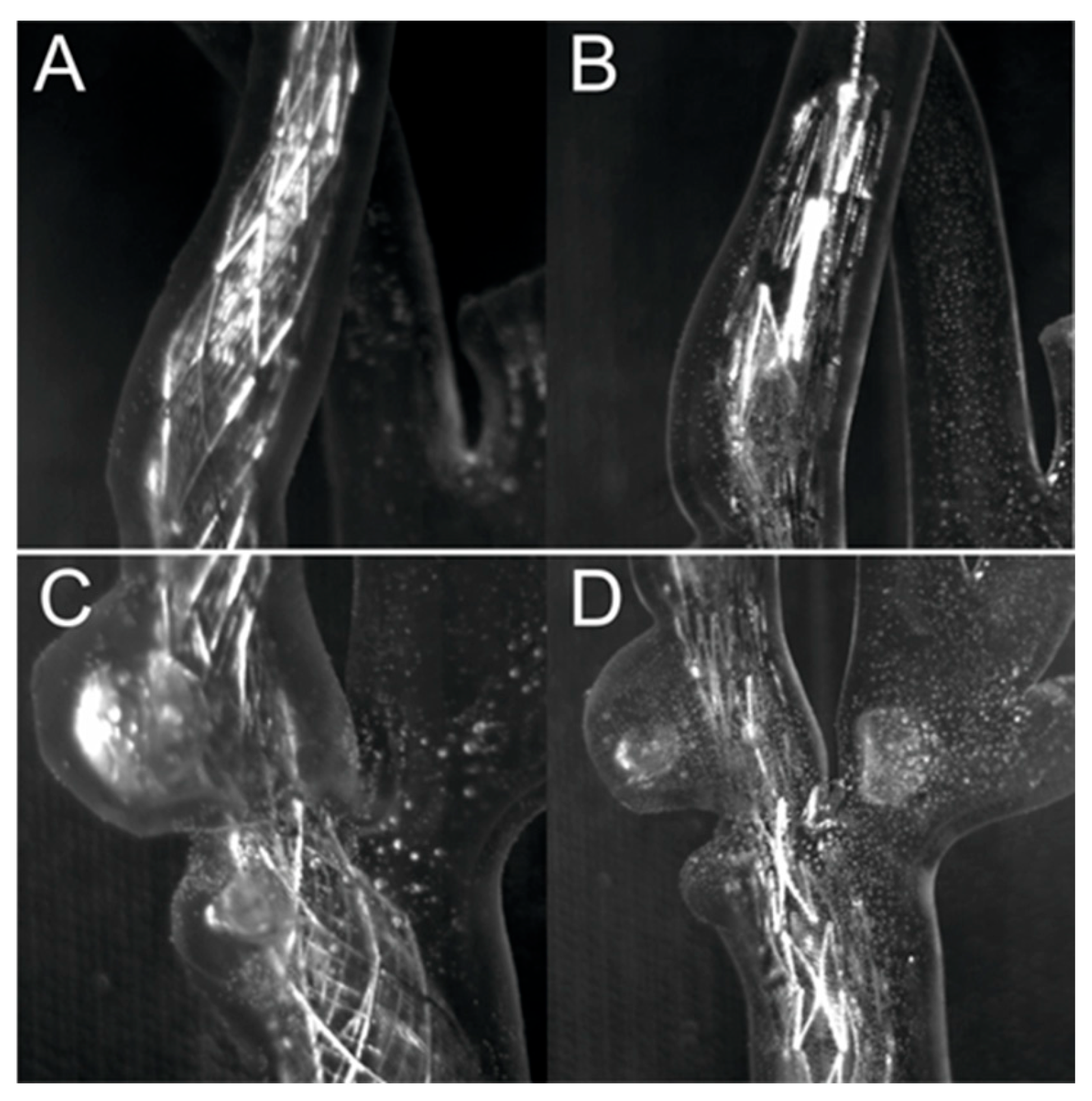
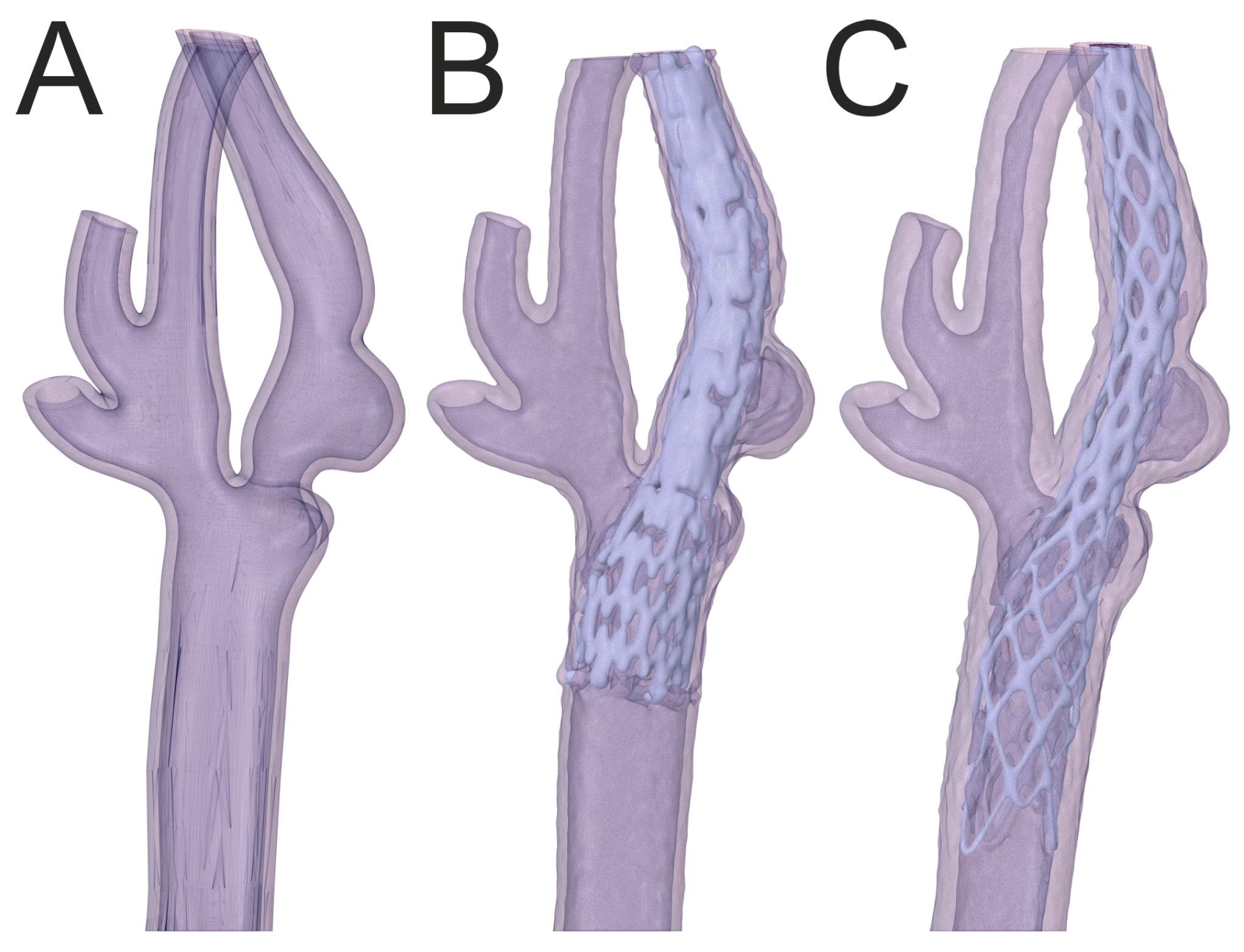
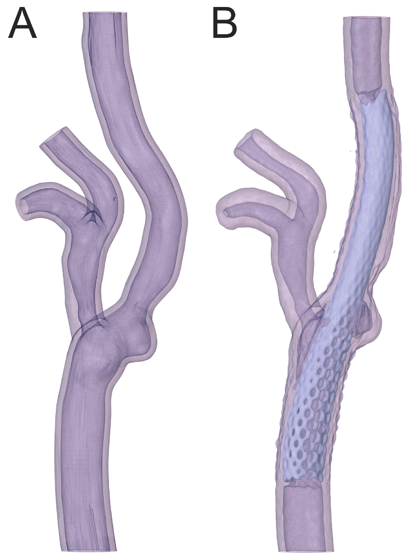
3.2. Percutaneous Carotid Artery Stenting on 3D-Printed Phantoms
4. Discussion
5. Limitations
6. Conclusions
Supplementary Materials
Author Contributions
Funding
Institutional Review Board Statement
Informed Consent Statement
Data Availability Statement
Conflicts of Interest
References
- Müller, M.D.; Lyrer, P.; Brown, M.M.; Bonati, L.H. Carotid Artery Stenting versus Endarterectomy for Treatment of Carotid Artery Stenosis. Cochrane Database Syst. Rev. 2020, 2020, CD000515. [Google Scholar]
- Aboyans, V.; Ricco, J.B.; Bartelink, M.L.E.L.; Björck, M.; Brodmann, M.; Cohnert, T.; Collet, J.P.; Czerny, M.; De Carlo, M.; Debus, S.; et al. 2017 ESC Guidelines on the Diagnosis and Treatment of Peripheral Arterial Diseases, in Collaboration with the European Society for Vascular Surgery (ESVS). Eur. Heart J. 2018, 39, 763–816. [Google Scholar] [CrossRef]
- Jedrzejek, M.; Kozłowski, M.; Peszek-Przybyła, E.; Jadczyk, T.; Pysz, P.; Wojakowski, W.; Smolka, G. Mitral Paravalvular Leak 3D Printing from 3D-Transesophageal Echocardiography. Anatol. J. Cardiol. 2023, 27, 573–579. [Google Scholar] [CrossRef]
- Moneta, G.L.; Edwards, J.M.; Chitwood, R.W.; Taylor, L.M.; Lee, R.W.; Cummings, C.A.; Porter, J.M. Correlation of North American Symptomatic Carotid Endarterectomy Trial (NASCET) Angiographic Definition of 70% to 99% Internal Carotid Artery Stenosis with Duplex Scanning. J. Vasc. Surg. 1993, 17, 152–159. [Google Scholar] [CrossRef]
- Josephson, S.A.; Bryant, S.O.; Mak, H.K.; Johnston, S.C.; Dillon, W.P.; Smith, W.S. Evaluation of Carotid Stenosis Using CT Angiography in the Initial Evaluation of Stroke and TIA. Neurology 2004, 63, 457. [Google Scholar] [CrossRef]
- Maurovich-Horvat, P.; Ferencik, M.; Voros, S.; Merkely, B.; Hoffmann, U. Comprehensive Plaque Assessment by Coronary CT Angiography. Nat. Rev. Cardiol. 2014, 11, 390–402. [Google Scholar] [CrossRef] [PubMed]
- Divakaran, S.; Cheezum, M.K.; Hulten, E.A.; Bittencourt, M.S.; Silverman, M.G.; Nasir, K.; Blankstein, R. Use of Cardiac CT and Calcium Scoring for Detecting Coronary Plaque: Implications on Prognosis and Patient Management. Br. J. Radiol. 2015, 88, 20140594. [Google Scholar] [CrossRef] [PubMed]
- Motoyama, S.; Ito, H.; Sarai, M.; Kondo, T.; Kawai, H.; Nagahara, Y.; Harigaya, H.; Kan, S.; Anno, H.; Takahashi, H.; et al. Plaque Characterization by Coronary Computed Tomography Angiography and the Likelihood of Acute Coronary Events in Mid-Term Follow-Up. J. Am. Coll. Cardiol. 2015, 66, 337–346. [Google Scholar] [CrossRef]
- Maurovich-Horvat, P.; Hoffmann, U.; Vorpahl, M.; Nakano, M.; Virmani, R.; Alkadhi, H. The Napkin-Ring Sign: CT Signature of High-Risk Coronary Plaques? JACC Cardiovasc. Imaging 2010, 3, 440–444. [Google Scholar] [CrossRef]
- Dweck, M.R.; Williams, M.C.; Moss, A.J.; Newby, D.E.; Fayad, Z.A. Computed Tomography and Cardiac Magnetic Resonance in Ischemic Heart Disease. J. Am. Coll. Cardiol. 2016, 68, 2201–2216. [Google Scholar] [CrossRef]
- Akçakaya, M.; Basha, T.A.; Chan, R.H.; Manning, W.J.; Nezafat, R. Accelerated Isotropic Sub-Millimeter Whole-Heart Coronary MRI: Compressed Sensing versus Parallel Imaging. Magn. Reson. Med. 2014, 71, 815–822. [Google Scholar] [CrossRef] [PubMed]
- Ong, W.Y.; Im, K.; Anias, E.G.D.; Atthias, M.; Tuber, S.; Lamm, C.D.F.; Ven, S.; Lein, P.; Agel, I.N.; Usan, S.; et al. Coronary Magnetic Resonance Angiography for the Detection of Coronary Stenoses. N. Engl. J. Med. 2001, 345, 1863–1869. [Google Scholar]
- Hatsukami, T.S.; Ross, R.; Polissar, N.L.; Yuan, C. Visualization of Fibrous Cap Thickness and Rupture in Human Atherosclerotic Carotid Plaque In Vivo With High-Resolution Magnetic Resonance Imaging. Circulation 2000, 102, 959–964. [Google Scholar] [CrossRef]
- Kerwin, W.S.; Zhao, X.; Chun, Y.; Hatsukami, T.S.; Maravilla, K.R.; Underhill, H.R.; Zhao, X. Contrast-Enhanced MRI of Carotid Atherosclerosis: Dependence on Contrast Agent. J. Magn. Reson. Imaging 2009, 30, 35–40. [Google Scholar] [CrossRef] [PubMed]
- Zhang, J.; Rothenberger, S.M.; Brindise, M.C.; Markl, M.; Rayz, V.L.; Vlachos, P.P. Wall Shear Stress Estimation for 4D Flow MRI Using Navier–Stokes Equation Correction. Ann. Biomed. Eng. 2022, 50, 1810–1825. [Google Scholar] [CrossRef]
- Nath, R.; Kazemi, A.; Callahan, S.; Stoddard, M.F.; Amini, A.A. 4Dflow-VP-Net: A Deep Convolutional Neural Network for Noninvasive Estimation of Relative Pressures in Stenotic Flows from 4D Flow MRI. Magn. Reson. Med. 2023, 90, 2175–2189. [Google Scholar] [CrossRef]
- Bouma, B.E.; Tearney, G.J.; Yabushita, H.; Shishkov, M.; Kauffman, C.R.; DeJoseph Gauthier, D.; MacNeill, B.D.; Houser, S.L.; Aretz, H.T.; Halpern, E.F.; et al. Evaluation of Intracoronary Stenting by Intravascular Optical Coherence Tomography. Heart 2003, 89, 317–320. [Google Scholar] [CrossRef]
- Jang, I.-K.; Bouma, B.E.; Kang, D.-H.; Park, S.-J.; Park, S.-W.; Seung, K.-B.; Choi, K.-B.; Shishkov, M.; Schlendorf, K.; Pomerantsev, E.; et al. Visualization of Coronary Atherosclerotic Plaques in Patients Using Optical Coherence Tomography: Comparison With Intravascular Ultrasound. J. Am. Coll. Cardiol. 2002, 39, 604–609. [Google Scholar] [CrossRef]
- Dohad, S.; Zhu, A.; Krishnan, S.; Wang, F.; Wang, S.; Cox, J.; Henry, T.D. Optical Coherence Tomography Guided Carotid Artery Stent Procedure: Technique and Potential Applications. Catheter. Cardiovasc. Interv. 2018, 91, 521–530. [Google Scholar] [CrossRef]
- Schwindt, A.G.; Bennett, J.G.; Crowder, W.H.; Dohad, S.; Janzer, S.F.; George, J.C.; Tedder, B.; Davis, T.P.; Cawich, I.M.; Gammon, R.S.; et al. Lower Extremity Revascularization Using Optical Coherence Tomography-Guided Directional Atherectomy: Final Results of the EValuation of the PantheriS Optical COherence Tomography ImagiNg Atherectomy System for Use in the Peripheral Vasculature (VISION) Study. J. Endovasc. Ther. 2017, 24, 355–366. [Google Scholar] [CrossRef] [PubMed]
- Araki, M.; Park, S.J.; Dauerman, H.L.; Uemura, S.; Kim, J.S.; Di Mario, C.; Johnson, T.W.; Guagliumi, G.; Kastrati, A.; Joner, M.; et al. Optical Coherence Tomography in Coronary Atherosclerosis Assessment and Intervention. Nat. Rev. Cardiol. 2022, 19, 684–703. [Google Scholar] [CrossRef]
- Waxman, S.; Dixon, S.R.; L’Allier, P.; Moses, J.W.; Petersen, J.L.; Cutlip, D.; Tardif, J.C.; Nesto, R.W.; Muller, J.E.; Hendricks, M.J.; et al. In Vivo Validation of a Catheter-Based Near-Infrared Spectroscopy System for Detection of Lipid Core Coronary Plaques. Initial Results of the SPECTACL Study. JACC Cardiovasc. Imaging 2009, 2, 858–868. [Google Scholar] [CrossRef] [PubMed]
- Finn, A.V.; Kolodgie, F.D.; Virmani, R. Correlation between Carotid Intimal/Medial Thickness and Atherosclerosis: A Point of View from Pathology. Arterioscler. Thromb. Vasc. Biol. 2010, 30, 177–181. [Google Scholar] [CrossRef]
- Lal, B.K.; Hobson, R.W.; Pappas, P.J.; Kubicka, R.; Hameed, M.; Chakhtura, E.Y.; Jamil, Z.; Padberg, F.T.; Haser, P.B.; Durán, W.N. Pixel Distribution Analysis of B-Mode Ultrasound Scan Images Predicts Histologic Features of Atherosclerotic Carotid Plaques. J. Vasc. Surg. 2002, 35, 1210–1217. [Google Scholar] [CrossRef]
- Noflatscher, M.; Hunjadi, M.; Schreinlechner, M.; Sommer, P.; Lener, D.; Theurl, M.; Kirchmair, R.; Bauer, A.; Ritsch, A.; Marschang, P. Inverse Correlation of Cholesterol Efflux Capacity with Peripheral Plaque Volume Measured by 3D Ultrasound. Biomedicines 2023, 11, 1918. [Google Scholar] [CrossRef]
- Hegner, A.; Wittek, A.; Derwich, W.; Huß, A.; Gámez, A.J.; Blase, C. Using Averaged Models from 4D Ultrasound Strain Imaging Allows to Significantly Differentiate Local Wall Strains in Calcified Regions of Abdominal Aortic Aneurysms. Biomech. Model. Mechanobiol. 2023, 22, 1709–1727. [Google Scholar] [CrossRef] [PubMed]
- Rynio, P.; Kazimierczak, A.; Jedrzejczak, T.; Gutowski, P. A 3-Dimensional Printed Aortic Arch Template to Facilitate the Creation of Physician-Modified Stent-Grafts. J. Endovasc. Ther. 2018, 25, 554–558. [Google Scholar] [CrossRef]
- Tong, Y.-H.; Yu, T.; Zhou, M.-J.; Liu, C.; Zhou, M.; Jiang, Q.; Liu, C.-J.; Li, X.-Q.; Liu, Z. Use of 3D Printing to Guide Creation of Fenestrations in Physician-Modified Stent-Grafts for Treatment of Thoracoabdominal Aortic Disease. J. Endovasc. Ther. 2020, 27, 385–393. [Google Scholar] [CrossRef] [PubMed]
- Branzan, D.; Geisler, A.; Grunert, R.; Steiner, S.; Bausback, Y.; Gockel, I.; Scheinert, D.; Schmidt, A. The Influence of 3D Printed Aortic Models on the Evolution of Physician Modified Stent Grafts for the Urgent Treatment of Thoraco-Abdominal and Pararenal Aortic Pathologies. Eur. J. Vasc. Endovasc. Surg. 2021, 61, 407–412. [Google Scholar] [CrossRef]
- Kohn, J.C.; Lampi, M.C.; Reinhart-King, C.A. Age-Related Vascular Stiffening: Causes and Consequences. Front. Genet. 2015, 6, 112. [Google Scholar] [CrossRef]
- Khanafer, K.; Duprey, A.; Zainal, M.; Schlicht, M.; Williams, D.; Berguer, R. Determination of the Elastic Modulus of Ascending Thoracic Aortic Aneurysm at Different Ranges of Pressure Using Uniaxial Tensile Testing. J. Thorac. Cardiovasc. Surg. 2011, 142, 682–686. [Google Scholar] [CrossRef]
- Wang, X.; Li, X. Computational Simulation of Aortic Aneurysm Using FSI Method: Influence of Blood Viscosity on Aneurismal Dynamic Behaviors. Comput. Biol. Med. 2011, 41, 812–821. [Google Scholar] [CrossRef] [PubMed]
- Rahdert, D.A.; Sweet, W.L.; Tio, F.O.; Janicki, C.; Duggan, D.M. Measurement of Density and Calcium in Human Atherosclerotic Plaque and Implications for Arterial Brachytherapy. Cardiovasc. Radiat. Med. 1999, 1, 358–367. [Google Scholar] [CrossRef] [PubMed]
- Łopianiak, I.; Rzempołuch, W.; Civelek, M.; Cicha, I.; Ciach, T.; Butruk-Raszeja, B.A. Multilayered Blow-Spun Vascular Prostheses with Luminal Surfaces in Nano/Micro Range: The Influence on Endothelial Cell and Platelet Adhesion. J. Biol. Eng. 2023, 17, 20. [Google Scholar] [CrossRef] [PubMed]
- Jędrzejczak, K.; Antonowicz, A.; Makowski, Ł.; Orciuch, W.; Wojtas, K.; Kozłowski, M. Computational Fluid Dynamics Validated by Micro Particle Image Velocimetry to Estimate the Risk of Hemolysis in Arteries with Atherosclerotic Lesions. Chem. Eng. Res. Des. 2023, 196, 342–353. [Google Scholar] [CrossRef]
- Illi, J.; Bernhard, B.; Nguyen, C.; Pilgrim, T.; Praz, F.; Gloeckler, M.; Windecker, S.; Haeberlin, A.; Gräni, C. Translating Imaging Into 3D Printed Cardiovascular Phantoms: A Systematic Review of Applications, Technologies, and Validation. JACC Basic. Transl. Sci. 2022, 7, 1050–1062. [Google Scholar] [CrossRef]
- Jędrzejek, M.; Peszek-Przybyła, E.; Jadczyk, T.; Zemik, J.; Piprek, P.; Pysz, P.; Kozłowski, M.; Wojakowski, W.; Smolka, G. 3D Printing from Transesophageal Echocardiography for Planning Mitral Paravalvular Leak Closure—Feasibility Study. Postep. W Kardiol. Interwencyjnej 2023, 19, 270–276. [Google Scholar] [CrossRef]
- Irnstorfer, N.; Unger, E.; Hojreh, A.; Homolka, P. An Anthropomorphic Phantom Representing a Prematurely Born Neonate for Digital X-Ray Imaging Using 3D Printing: Proof of Concept and Comparison of Image Quality from Different Systems. Sci. Rep. 2019, 9, 14357. [Google Scholar] [CrossRef] [PubMed]
- Otton, J.M.; Birbara, N.S.; Hussain, T.; Greil, G.; Foley, T.A.; Pather, N. 3D Printing from Cardiovascular CT: A Practical Guide and Review. Cardiovasc. Diagn. Ther. 2017, 7, 507–526. [Google Scholar] [CrossRef]
- Castro-Sastre, M.Á.; Fernández-Abia, A.I.; Piep, J.; Rodríguez-González, P.; Barreiro, J. Towards Functional Parts by Binder Jetting Calcium-Sulphate with Thermal Treatment Post-Processing. Materials 2020, 13, 3818. [Google Scholar] [CrossRef]
- Salmi, M. Additive Manufacturing Processes in Medical Applications. Materials 2021, 14, 191. [Google Scholar] [CrossRef] [PubMed]


| Stent Type | Roadsaver™ | Protégé™ RX | WALLSTENT™ |
|---|---|---|---|
| Company | Terumo (Leuven, Belgium) | Medtronic (Plymouth, MA, USA) | Boston Scientific (Marlborough, MA, USA) |
| Type of the stent | Closed cell–braided | Open cell–laser cut | Closed cell–braided |
| Layers | Double layers | Monolayer | Monolayer |
| Free cell area [mm2] | 0.0381 | 10.71 | 1.09 |
| Material | Nitinol | Nitinol | Cobalt–chromium |
| Scaffolding (metal–artery ratio) [%] | 39 | 29 | 15 |
| Foreshortening [%] | 27 | 8 | 49 |
| Parameter | Value |
|---|---|
| Resin type | Biomed Elastic 50A V1 |
| Average print time | 12 h |
| Average post-processing time | 4 h |
| Material refractive index | 1.473 ± 0.002 [-] |
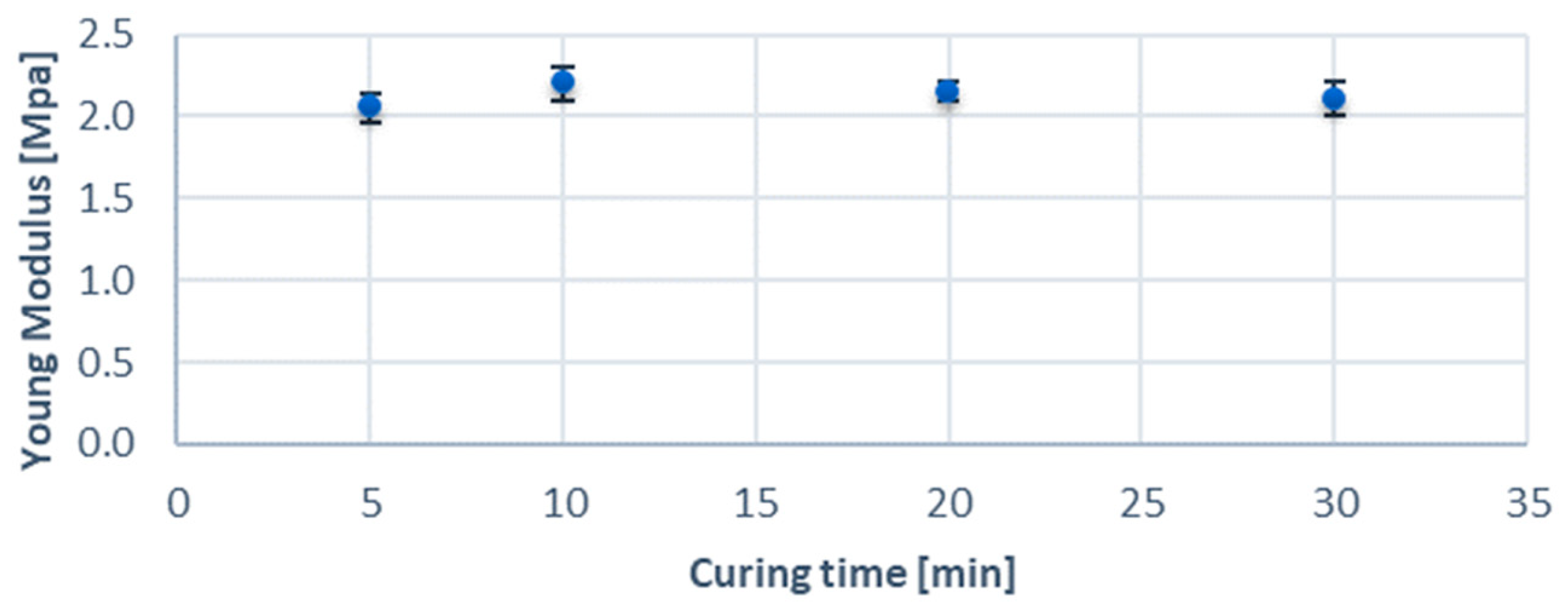
| Young’s modulus | 2.13 ± 0.05 MPa |
| Density of a 3D print | 1059 ± 22 kg/m3 |
Disclaimer/Publisher’s Note: The statements, opinions and data contained in all publications are solely those of the individual author(s) and contributor(s) and not of MDPI and/or the editor(s). MDPI and/or the editor(s) disclaim responsibility for any injury to people or property resulting from any ideas, methods, instructions or products referred to in the content. |
© 2024 by the authors. Licensee MDPI, Basel, Switzerland. This article is an open access article distributed under the terms and conditions of the Creative Commons Attribution (CC BY) license (https://creativecommons.org/licenses/by/4.0/).
Share and Cite
Jędrzejczak, K.; Antonowicz, A.; Butruk-Raszeja, B.; Orciuch, W.; Wojtas, K.; Piasecki, P.; Narloch, J.; Wierzbicki, M.; Makowski, Ł. Three-Dimensionally Printed Elastic Cardiovascular Phantoms for Carotid Angioplasty Training and Personalized Healthcare. J. Clin. Med. 2024, 13, 5115. https://doi.org/10.3390/jcm13175115
Jędrzejczak K, Antonowicz A, Butruk-Raszeja B, Orciuch W, Wojtas K, Piasecki P, Narloch J, Wierzbicki M, Makowski Ł. Three-Dimensionally Printed Elastic Cardiovascular Phantoms for Carotid Angioplasty Training and Personalized Healthcare. Journal of Clinical Medicine. 2024; 13(17):5115. https://doi.org/10.3390/jcm13175115
Chicago/Turabian StyleJędrzejczak, Krystian, Arkadiusz Antonowicz, Beata Butruk-Raszeja, Wojciech Orciuch, Krzysztof Wojtas, Piotr Piasecki, Jerzy Narloch, Marek Wierzbicki, and Łukasz Makowski. 2024. "Three-Dimensionally Printed Elastic Cardiovascular Phantoms for Carotid Angioplasty Training and Personalized Healthcare" Journal of Clinical Medicine 13, no. 17: 5115. https://doi.org/10.3390/jcm13175115
APA StyleJędrzejczak, K., Antonowicz, A., Butruk-Raszeja, B., Orciuch, W., Wojtas, K., Piasecki, P., Narloch, J., Wierzbicki, M., & Makowski, Ł. (2024). Three-Dimensionally Printed Elastic Cardiovascular Phantoms for Carotid Angioplasty Training and Personalized Healthcare. Journal of Clinical Medicine, 13(17), 5115. https://doi.org/10.3390/jcm13175115