Article

Optimization of Clamping and Conveying Device for Sunflower Oil Combine Harvester Header

1
College of Engineering, Huazhong Agricultural University, Wuhan 430070, China
2
Key Laboratory of Agricultural Equipment in Mid-Lower Yangtze River, Ministry of Agriculture and Rural Affairs, Wuhan 430070, China
*
Author to whom correspondence should be addressed.
Agriculture 2021, 11(9), 859; https://doi.org/10.3390/agriculture11090859
Submission received: 13 August 2021 / Accepted: 26 August 2021 / Published: 8 September 2021
(This article belongs to the Section Agricultural Technology)

Abstract

:
To solve the problem of grain spatter during harvest by combine harvester headers, a new clamping and conveying device of the sunflower oil harvester header was designed. We investigated plant states during the conveying process. To optimize the parameters of the sunflower oil harvester header, a test bench was built to simulate sunflower plant harvest. The influence of the clamping gap, clamping speed ratio, and clamping length on conveying success rate was explored by a single-factor experiment. Based on this experiment, the secondary regression orthogonal rotation test was carried out. The optimal structural parameter combination was obtained as follows: the clamping gap was 20 mm, the clamping speed ratio was 1.3, and the clamping length was 345 mm. Under this combination parameter condition, the corresponding conveying success rate reached up to 85.16% and the minimum value of conveying grain loss rate was 1.57%. To verify the effect of parameter optimization, a verification test and a comparison test were performed. Results showed that the actual conveying success rate was 83.50% and the actual grain loss rate was 1.49%, which were close to the optimized parameter value. The comparison test showed that the conveying success rate of the flexible clamping and conveying device was 83.50% with a grain loss rate of 1.49%, and that of the rigid clamping and conveying device was 55% with a grain loss rate of 5.17%. This study provides a theoretical basis for the design of a low-loss sunflower oil combine harvester header.

1. Introduction

Sunflower oil is the world’s fourth largest oil crop [1,2], with a planting area of 1.33 million hectares in China [3]. The artificial harvest of sunflower oil is expensive and inefficient. Therefore, the mechanized harvesting of sunflower oil represents a trend of development in the future. An important link in the mechanized harvest process is conveying the sunflower oil plants to the combine harvester header. Great loss in the harvest process often occurs at the header, which poses a bottleneck and has restricted the development of mechanized harvesting technology of sunflower oil. Therefore, it is urgent to explore new techniques for minimizing loss during the harvest [4,5].
There are two common harvesting methods for sunflower oil. One method utilizes the traditional plucking wheel to pluck plants. During harvesting, the crop is rotated and thrown into the screw conveyor by the plucking wheel. The friction between the plant and the bottom plate and the collision of plant against the header results in grain loss and broken sunflower disks [6,7]. Besides, the large wheel is space-consuming [8,9,10].
Another harvest method uses a rigid chain of crop, which forces the plant into the combine harvester’s header, resulting in great loss due to violent vibration [11,12].
To reduce the loss of plants in the process of cutting and conveying, some scholars at home and abroad have explored new harvesting methods. For example, some researchers designed the flexible clamping conveyor for vegetable harvesting [13,14,15]. Other researchers attempted to optimize the corn harvester header clamping conveyor [16,17]. The above harvesting methods are useful for strong-stem crops and for those whose grains do not drop easily, such as corn. Some scholars have proposed flexible delivery methods. Yang et al. suggested the technology of flexible clamping with three clamps, which was applicable to the harvest of underground crops [18].
A. S., et al. developed an auger-reel equipped with a winding, which allows reducing the acceleration of sunflower head movement during harvesting and minimizes the loss of oilseeds behind the header to 0.63% [19]. Dahab, M. H.; Elsheikh, A. O. et al. attempted to reduce the header loss rate by optimizing the header parts and exploring the influence of water content and walking speed on header loss rate [20]. Ghiasi et al. researched the influence of bar height and header height on sunflower loss and modeled grain losses during mechanized harvesting of sunflower oil [21].
Traditionally, sunflower oil harvest loss was mainly caused by unsuccessful harvesting, through collision loss and vibration loss of the sunflower oil plant during transportation. Considering the biological characteristics of the plants, such as being easy to break, easy to spatter, and the difference in plant height, a new device was designed for sunflower oil harvesting based on the principle of flexible gripping and conveying. To study structural parameters and working parameters of the clamping conveyor during the harvest process of sunflower oil, the bench test was carried out by the Box Benhnken Design (BBD) center combination design method. The working performance was tested by field experiment to verify the accuracy of the device parameters and to provide a reference for the design of the sunflower oil combine harvester header.

2. Materials and Methods

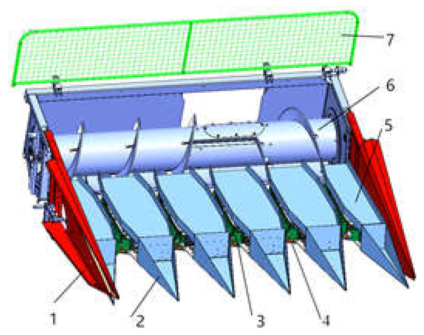
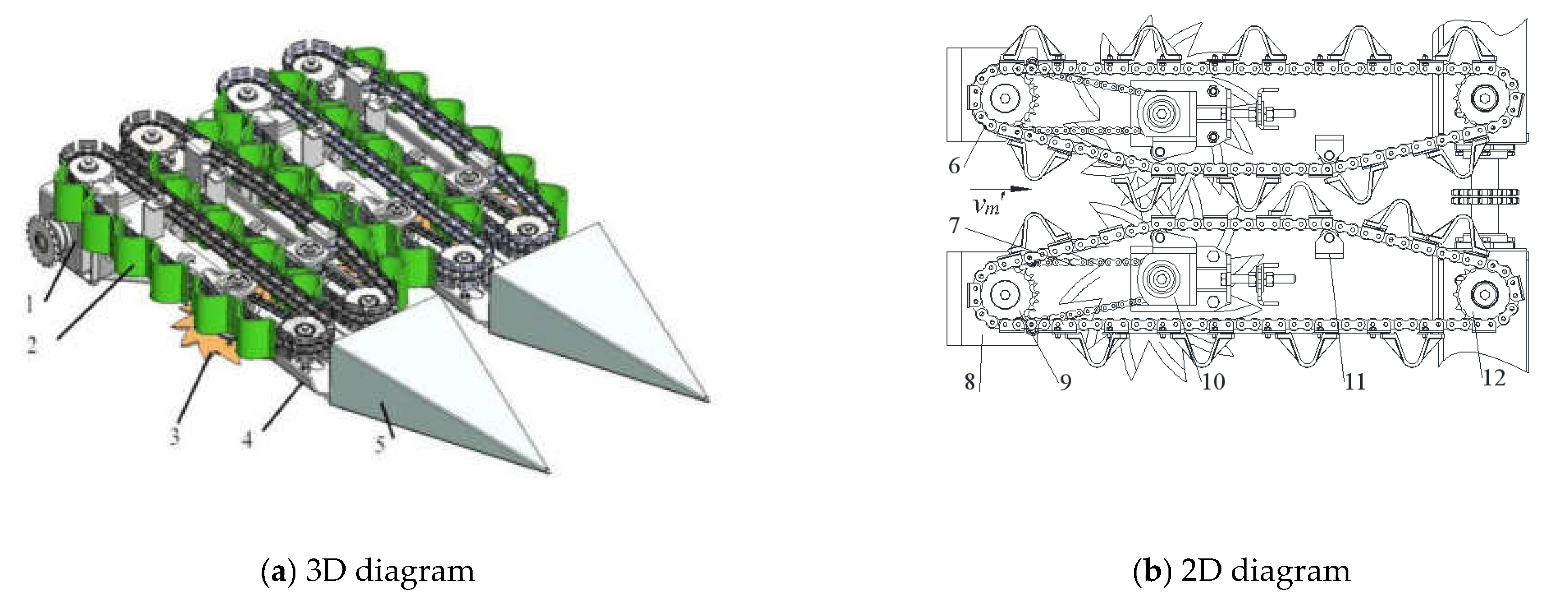
2.1. Structural Design

Based on the principle of plucking and clamping conveying, a flexible clamping and conveying device for sunflower oil combine header was designed (Figure 1).
As shown in Figure 2, the flexible clamping conveying device was composed of an active feeding sprocket, follower feeding sprocket, conveying chain, flexible plucking element, rotary cutter, cutter power sprocket, and other parts.

2.2. Operation Principle

While working, the gearbox drives the active sprocket; the driven sprocket; and the conveying chain, which further drives the cutter chain.
Movement of the sunflower oil plant includes two processes, namely, the raking crop process and the clamping transport process. During the raking crop process, the momentum of the collision can be converted into the potential energy of the clamping element due to the flexible surface and the buffering effect of the flexible element; thus, grain loss caused by collision can be reduced when the sunflower oil is plucked in the harvest period.
During the clamping and conveying process, the relative speed of two clamping elements (A and B) is zero, which renders the device capable of clamping and smoothly conveying the sunflower oil to the screw conveyor similar to the “hand”, thus reducing the loss of grain drop in the conveying process.

2.3. Design of the Key Parameters

During working, the clamping and conveying device should meet the reel grain and lifting branches functions of the plant, while reduce the impact on the plant. Combined with the chain conveying capacity, the 12A chain with side plate was selected and flexible clamping elements were installed onto it, which can achieve effective threshing for different running distances and declining sunflower oil; the layout of the conveying chain is shown in Figure 3. Its key parameters include conveying chain parameters and clamping element structural parameters.

2.3.1. The Design of Conveying Chain Parameters

The key parameters of clamping and conveying device include the central distance, chain front inclination, chain rear inclination, etc. These parameters were designed as follows:

Center Distance

The conveying chain was installed at the bottom of the crop divider; its overall layout is shown in Figure 3a. To ensure that the fallen grain can be collected by the shattering recovery tank, according to the structure size of the hopper and the spatial layout of the conveying chain, the longitudinal length of the chain should meet the following conditions:
L s c L x + ( D l + D C ) 2 + C S
where Lsc is the length of dropping grain collected slot, mm; LX is the center distance between the active sprocket and driven sprocket, mm; DC is the driven sprocket diameter, mm; Dl is the diameter of active sprocket, mm; Cs is the length of dial fingers, mm.
Substituting those parameters with the diameter of active sprocket Dl = 120 mm, the diameter of driven sprocket DC = 100 mm, the length of dial fingers Cs = 50 mm, and the length of dropping grain collected slot Lsc = 960 mm into Formula (1), we obtained LX 800 mm; thus, LX was set to 800 mm.

The Front Inclination Angle of Chain

The plant moved backwards opposite the machine walk (reel speed is shown in Figure 3b) to ensure that the plant could be successfully clamped and conveyed; then, the line speed of conveying chain along the machine walking direction speed should be greater than or equal to the machine forward speed, specifically,
v r cos a b v m
where ab is the chain front inclination angle, which is the clip angle between the conveying chain and the forward direction of the machine, °; vr is the speed of conveying chain, m/s; vm is the speed of combine harvester walk, m/s.
According to the agricultural machinery design manual, the speed range of the existing harvester was 0.8~2.5 m/s and its speed range of machine walking was 0.5~2.2 m/s [22,23]. The above parameters were substituted into (2), obtaining the available range of ab as ab ≤ 28.35°. Considering the machining and sprocket installation, ab was set to 25°.

The Angle of Chain Rear Inclination

The throwing speed is shown in Figure 3c. To ensure that the sunflower oil plant could be captured by the spiral conveyor and avoid reaching the bottom of the chain, when the plant reaches the spiral conveyor, the offset distance of the vertical machine direction was not greater than the distance from the center to the moving sprocket; when the plant was transported to the spiral conveyor, the minimum distance from conveying chain to spiral blade was not greater than the distance between the center of the two crop dividers and the center of the driven sprocket. Thus,
h j v r cos a h s j v r sin a h
where ah is chain rear inclination angle, which was the angle between the conveying chain and the forward direction of the machine, °; hj is the minimum distance from conveying chain to spiral blade, mm; sj is the distance that between the center of the two crop dividers and the center of the driven sprocket, mm.
To prevent dial finger interference with the spiral blade, we set a certain surplus Δε = 10~20 mm according to its spatial position, so there was
{ h j C s + Δ ε s j D c 2 + S f 2
where Δε is the minimum distance from the grain element to the spiral blade, mm; Sf is the gap between two crop divider, mm. Substituting Formula (4) into Formula (3), we obtain Formula (5), as shown below:
tan a h s j h j
The parameters Sf = 60 mm, Cs = 50 mm, Δε = 20 mm, and Dc = 100 mm were substituted into Formula (5); the range of chain rear inclination angle that could be acquired was ah ≥ 41.19°; for easy installation, ah was set to 42°.

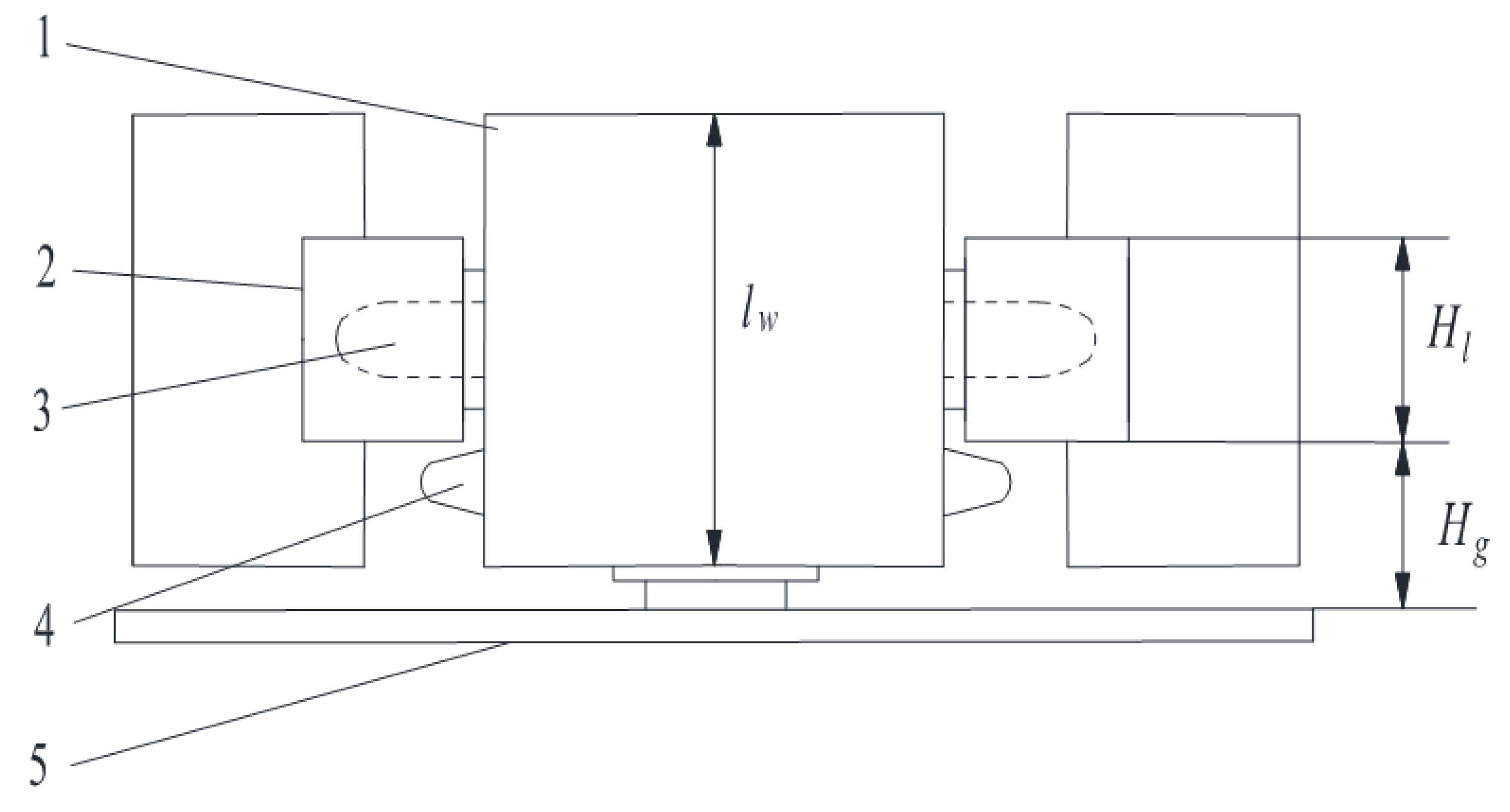
2.3.2. The Design of Clamping Element Parameters

The main included parameters of the clamping element were the height of the clamping element, the mounting width of clamping element, and the width and the thickness of the clamping element. A schematic diagram of the clamping element is shown in Figure 4.

Height of the Clamping Element

The height of the clamping element refers to the distance from the peak to the bottom, which determines whether the plant could be effectively moved. To ensure effective reeling, the height of the holding element should be greater than the maximum diameter of the plant. To ensure that all plants are stably held at the tip, the plant at its minimum diameter will be in tight contact, so there are
d max H b S f H h d min
where Hb is the height of the clamping element, mm; dmax is the maximum diameter plant, mm; dmin is the minimum diameter of plant, mm; Hh is the thickness of clamping, mm.
We selected the thickness of the clamping element Hh = 5 mm; the parameters dmax 32 mm and dmin 9.92 mm were gained through a filed survey; the gap of crop divider Sf, from the previous analysis, was equal to 60 mm. Those parameters were substituted into Formula (6), obtaining the range of Hb that could be acquired as 32 H b 46.08 mm. For convenience of processing, we chose Hb = 45 mm.

The Mounting Width of Clamping Element

The installation width of the clamping element is shown in Figure 4. If the value is too large, the grain strength of the clamping element will be too weak; if the value is too small, it will not be conducive to the installation of the clamping element. According to the geometric relationship in the graph, the clamping element mounting width meets the following requirements:
{ a b ¯ H s α b 1 < α b 2 tan α b 1 = 2 ( H b H h ) a b ¯
2 ( H b H h ) tan α b 2 < H s
The siding angle and the installation surface of the grain chain should be less than the corresponding friction angle, namely, α b 1 φ b 2 , which was substituted in Formula (8), obtaining
2 ( H b H h ) tan φ b 2 < H s
In Formula (9), Hs is the mounting width of the clamping element, mm; φb2 is the friction angle between the clamping element and the plant, °.
Measuring the friction angle of the clamping element with a ripple, φb2 = 47.5°. The parameters Hb = 45 mm, Hh = 5 mm were gained from previous content, which were substituted into Formula (9); thus, the range of Hs was obtained: 75.91 H s . Combining these, the installation chain was chosen as 12A chain and its pitch was 19.05 mm. Depending on the space position, the clamping element width should be in integer intervals of the pitch; thus, we chose Hs = 76 mm.

The Width of Clamping Element

From the walking direction of the machine, the installation schematic diagram of the clamping element is shown in Figure 5, which shows that the width of the clamping element should meet Formula (10).
H l l w 2 H g + H l
In Formula (10), lw is the width of clamping, mm; Hl is the width of conveying chain attachment, mm; Hg is the distance between the grain chain attachment and the mounting base plate, mm.
The conveying chain was selected in this article as 12A industrial chain and the corresponding attachment width Hl was 56.40 mm, the distance between the grain chain attachment and the installation base plate Hg was 22.50 mm. Substituting the above parameters into Formula (10), the clamping element width range acquired was 56.40 ≤ Hk ≤ 101.4 mm. Considering that the common size of PVC is 60 mm and 80 mm, the width of the clamping element was chosen as 80 mm.

2.4. Principle Analysis of the Clamping

The sunflower oil plant was clamped by concave and convex flexible elements to form a force seal [24,25,26], which results effective clamping of the sunflower oil plant. The clamping model is shown in Figure 6.
According to Figure 6a, the plant statics model is expressed in the following Formula (11):
{ F x = F 1 x + F 2 x + F 3 x + F 4 x = 0 F y = F 1 y + F 2 y + F 3 y + F 4 y = 0 F z = f 1 + f 2 + f 3 + f 4 G = 0 f i = F i u
According to Figure 6b, the torque equation at point A and point B is as follows:
{ 2 F a l G ( l 0 cos β s 2 ) = 0 2 F b l G ( l 0 cos β + s 2 ) = 0
Solution:
{ F a = 2 l 0 cos β s 4 s G F b = 2 l 0 cos β + s 4 s G
Based on the geometric position in Figure 3b, the following equation is established:
s tan β + d 0 cos β = d 1
Solution:
cos β = d 0 d 1 s tan β
By inserting Formula (15) into (13), the clamping forces are obtained as follows:
{ F a = 2 l 0 d 0 s ( d 1 s tan β ) 4 s ( d 1 s tan β ) G F b = 2 l 0 d 0 + s ( d 1 s tan β ) 4 s ( d 1 s tan β ) G
Clamping force determines the effect of plant transport. Formula (16) shows that the clamping forces (Fa and Fb) are related to the width of clamping elements, s; the distance from plant gravity center to the clamping element gravity center, l0; the diameter of plant, d0; the clamping gap, d1; the gravity of plant, G; and the offset angle, which is the angle between the plant and the vertical direction, β.
In addition, plant movement comprised the movement of the clamping element and the movement of the combine harvester. As a result, the ratio of the above two movement speeds (k) affects the effect of plant conveying.
In Formula (11), F1, F2, F3, and F4 are the support forces from clamping elements; f1, f2, f3, and f4 represent the vertical friction forces received by the plant; F1x, F2x, F3x, and F4x represent the component forces along the x axis; F1y, F2y, F3y, and F4y represent the component forces along the y axis; and u is the friction coefficient between the stem and the clamping element. It is difficult to measure l0 in Formula (16) during this experiment; therefore, l1—indicating the length of the plant above the clamping element—is selected to approximately replace l0. In this study, the effects of clamping gap, d1; clamping speed ratio, k; and clamping length, l1, on plant conveying were explored.

2.5. Methods and Materials of Bench Tests

2.5.1. Materials and Devices

The experiment was carried out in the City of Huangshi, Hubei Province on 20 August 2019 with the “short head XC567” sunflower oil variety as material. Material characteristics are shown in Table 1. The test bench comprised the clamping and conveying device, cutter system, plant conveyer, and other components, as shown in Figure 7. The power of these devices was supplied independently by their respective motors, whose parameters were adjusted by the corresponding frequency converter.
The working principle of the test bench was as follows: First, the plant was delivered by the plant-feeding device; then, it was cut at the proper cutting point by the cutter. Subsequently, it was transported to the tail of the test bench by the flexible clamping and conveying device. Finally, the plant was discharged from the outlet of test bench by the screw conveyor.
According to the principle of relative motion, if the plant conveying device is assumed as relatively static, the test bench can be regarded as moving towards the plant, which simulates the working procedures of the combine harvester in the field.

2.5.2. Selection of Factor Parameters

Based on the above mentioned theoretical analysis, factors such as the height of plant clamping (l1, mentioned above), the speed ratio of clamping conveying device and combine harvester, and the gap between clamping elements (A and B in Figure 3) were defined as the experimental factors.
  • The Clamping Speed Ratio
The plant movement speed was affected by both the conveying speed of the sunflower oil clamping/conveying device vr and the moving speed of combine harvester vm [27]. A suitable speed ratio can provide the corresponding theoretical reference for the design and parameter optimization of the flexible clamping and conveying device. If the speed ratio is too large, the plant is easier to knock down; if too small, the plant is not easy to convey. The plant movement is shown in Figure 8.
{ v r sin α = v m sin ( 180 γ α ) α β = 90
The speed ratio obtained from formula (17) was calculated as follows:
k = v r v m = cos β cos ( γ + β )
where k is clamp speed ratio; α is the angle between the plant and the horizontal line, °; β is the angle between the plant and the vertical line, °; γ is the angle between header and ground, °.
During the actual clamping and conveying process, the value β of the plant inclination ranged from 5° to 30° [28] and the value of γ angle between the header and ground ranged from 10° to 30° [29]. By substituting the above parameters into Formula (18), the speed ratio range was found to be 1.03 ≤ k ≤ 1.73. Therefore, in the single-factor test, the speed ratio factor selection range was defined as 1.0 ≤ k ≤ 1.8; thus, within the range, the parameters 1.0, 1.2, 1.4, 1.6, and 1.8 were selected as the speed ratio levels in the single-factor test.
2.
The Clamping Gap
When the gap between clamping elements was too large, the plant was easy to fall, but when the gap was too small, transportation blockage easily occurred. Considering that the diameter range of sunflower oil was 18.72 mm–41.3 mm, the clamping gap factor selection range was defined as 10 ≤ d1 ≤ 50; thus, within the range, the parameters 10 mm, 20 mm, 30 mm, 40 mm, and 50 mm were selected as the clamping gap levels in the single-factor test.
3.
The Clamping Length
The test results indicated that, when the clamped plant was too long, the plant was easily inclined, resulting in the failure of transportation; when it was too short, it was easy for the plant to fall out of the crop divider, causing grain loss. To facilitate subsequent threshing and cleaning, the clamped plant was cut to a length of no more than 1/3 of the entire crop length [30]. Since the plant length range was within 452 mm ≦ L ≦ 1965 mm (Table 1), the range of clamping length factor range was defined as 150.6 ≦ L0≦ 655 mm; thus, within the range, the parameters 150 mm, 250 mm, 350 mm, 450 mm, 550 mm, and 650 mm were selected as the clamping length levels in the single-factor test.

2.5.3. Appraisal Indexes

  • The Conveying Success Rate
The conveying success rate was equal to the percentage of plants successfully transported in each group and the total number of plants transported. The plant conveying device can convey 10 sunflower oil plants each time. Each group test was repeated four times, conveying a total of 40 sunflower oil plants. The test was conducted in triplicate to obtain the average value. The conveying success rate was calculated as follows:
k = v r v m = cos β cos ( γ + β )
where y1 is the plant conveying success rate, %; n is the total number of conveyed plants; and n0 is the number of plants successfully conveyed.
2.
The Grain Loss Rate
After each group of experiments, the successful conveying sunflower disk was threshed, and then the seed were weighed. At the same time, the dropped grain and the sunflower discs that failed to convey were threshed, and then the seed were weighed. Grain loss rate was defined as the percentage of the mass of seeds that failed to be transported in each group and the total mass of seeds successfully transported. The test was conducted in triplicate to obtain the average value. The grain loss rate was calculated as follows:
y 2 = m 1 m 1 + m 2 × 100 %
where y2 is the grain loss rate, %; m1 is the sum of the mass of the seed dropped in conveying and the grain in the sunflower that failed to be conveyed, g; and m2 is the mass of seed in sunflower successfully conveyed.

3. Results and Discussion

The single-factor test was conducted first to select a suitable factor range. Based on its results, an orthogonal test was performed to obtain the structural parameters and motion parameters of the device.
Before the experiment, a sunflower oil plant with a diameter close to 25 mm was inserted into the fixed tube of the plant conveying device, and the motor of the plant conveying device was started.
The speed of the plant conveying device was adjusted to 1.0 m/s by a frequency converter, and plants with different clamping lengths were prepared from sunflower oil plants of different heights. The clamping gap was adjusted by adjusting clamping chain gap.

3.1. Analysis of Single-Factor Test and Results

As shown in Figure 9a, with the increase in the clamping gap, the conveying success rate first increases and then decreases; furthermore, the grain loss rate decreases first and then increases. Within the range of 20~60 mm, with the increase of clamping gap, the swing amplitude of plant transportation process becomes larger, resulting an increase in plant grain loss. The clearance of the plucking chain was better in the range of 20~40 mm; within this range, the loss rate of grain was low and the success rate of transportation was better.
As shown in Figure 9b, the success rate of plant conveying first increased and then decreased with the increasing speed ratio; the law of grain loss change was that the grain loss rate was small with clamping speed ratio within the range of 1.0~1.2. When the clamping speed ratio was greater than 1.2, the loss rate of falling grain increases linearly with clamping speed ratio.
As shown in Figure 9c, with the increase in the clamped plant length, the success rate of plant conveying first increased, and then decreased. The falling grain loss changed subtly under the clamping length change at 150~350 mm, increasing with the clamping length.

3.2. Analysis of Orthogonal Test Results

To determine an optimal combination of parameters, a three-factor, three-level, secondary regression, orthogonal rotation combination test was designed [31,32]. A total of 17 group tests were conducted, each repeated three times to find the mean value. Based on the analysis of the single-factor experiment, the two-rotation orthogonal combination test was conducted. The coding of test factors is shown in Table 2.
The results of the quadratic rotation orthogonal combination test are shown in Table 3. The regression equation of clamping gap, clamping speed ratio, and clamping length versus the plant conveying success rate was established by using the Design-Expert data processing software to analyze experimental results.
The variance analysis results showed that plant conveying success rate and the grain loss rate model were significant, with significance values p of 0.008 and 0.001, respectively (p < 0.01), while misfit (p > 0.05) was not significant (Table 4). The variance analysis results showed that the regression model of the plant conveying success rate was well-fitted with the actual values.
The significance analysis results indicate that the clamping gap and clamping length has a significant effect on plant conveying success rate (p < 0.01). The effects of three factors on conveying success rate are ranked as follows: clamping gap > clamping length > clamping speed ratio. The significance analysis results indicate that the above factors have a significant effect on grain loss rate (p < 0.01). The effects of three factors on grain loss rate are ranked as follows: clamping length > clamping gap > clamping speed ratio.
After removing the insignificant factors, the regression equation of the plant conveying success rate Y1 and the grain loss rate Y2 were as follows:
Y1 = 16.8 − 2.16x1 + 88.3x2 + 0.188x3 − 0.0077x1·x1 − 34.9x2·x2 − 0.000098x3·x3 + 1.250x1·x2 + 0.00083x1·x3 − 0.0729x2·x3
Y2 = 0.0250 + 0.00027x1 − 0.0560x2 + 0.000012x3 + 0.000032x1·x1 + 0.0462x2·x2 + 0.000001x3·x3 + 0.000713xx2 − 0.000008x1·x3 − 0.000224x2·x3

3.3. Parameter Optimization

The target function value was larger, the parameters were better. The target function Z was expressed as follows:
{ m a x Y 1 ( x 1 , x 2 , x 3 ) min Y 2 ( x 1 , x 2 , x 3 ) s . t . { 20 mm x 1 40 mm 1.2 x 2 1.6 250 mm x 3 450 mm
The optimal parameter combination solution was obtained by MATLAB software with a clamping gap of 20 mm, clamping speed ratio of 1.27, and clamping length of 344.8 mm. After rounding, the parameter combination was a clamping gap of 20 mm, clamping speed ratio of 1.3, and clamping length of 345 mm. Under this condition, the maximum value of conveying success rate was 85.16% and the minimum value of conveying grain loss rate was 1.57%.

3.4. Verification Tests

Verification tests were carried out under the parameter combination of 20 mm clamping gap, clamping speed ratio of 1.3, and 345 mm clamping length. The verification tests were performed in triplicate and the average value was calculated, as shown in Table 5. The verification test results showed that the actual values were close to the predicted values; thus, the test results were reliable.

3.5. Contrast Test

To further reveal the performances of rigid and flexible conveying, a comparative experiment was carried out with the success rate of plant conveying and the loss rate of falling grain as evaluation indexes. At the end of each experiment, the dropped grain and the dropped sunflower discs were threshed and weighed. Each group experiment was repeated three times to obtain the mean value.
The comparison test results showed that the conveying success rate of flexible clamping conveyer was 83.50% and the loss of falling grain was 1.49%, while conveying success rate of rigid clamping conveyor was 55% and the loss of falling grain was 5.17%. The effect of a flexible plucking chain was better than that of a rigid plucking chain (Table 6).

4. Discussion

4.1. Effect of Clamping Gap on Conveying Success Rate and Grain Loss Rate

The law of the conveying success rate changed as shown in Figure 9a. The possible reason might be that when the clamping gap was larger than the plant diameter, the plant was more likely to be inclined, leading to a decrease in the conveying success rate. The clamping gap was too large, and the clamping force acting on the plant was reduced; therefore, it was easy for the plant to tilt and slide out, leading to the decreased success rate of plant conveying.
The law of the grain loss rate changed as shown in Figure 9a. The reason was that the gap of plucking chain is easily blocked at 10–20 mm, and the loss rate of falling grain was higher. As the clamping gap continues to increase, the clogging rate decreased, so the grain loss rate decreased briefly. Considering the success rate of plant conveying and grain loss rate, the clamping gap range was defined as 20 mm–40 mm.

4.2. Effect of Clamping Speed Ratio on Conveying Success Rate and Grain Loss Rate

The law of conveying success rate changed as shown in Figure 9b, which may be attributed to the fact that when the speed was low, the relative collision force acting on the plant was relatively small, which was favorable for the adjustment of plant posture, thus improving the success rate of plant conveying. With the increase in the speed ratio, the plant conveying success rate decreased. This might be due to the large relative speed, which could easily pull the plant down. In addition, with the increased speed ratio, the plant was more likely to be stuck in the gap between the crop divider and the clamp chain, which also increased the probability of conveying failure.
The law of the grain loss rate changed as shown in Figure 9b. The reason may be attributed to the fact that when the relative speed was small, the impact of the element on the plant was small, so the impact loss was small. With the increase of velocity ratio, the relative velocity increased, the impact increased, and the swing of transportation process increased, which led to the increase in grain loss. Considering the above, the range of speed ratio was determined as 1.2–1.6.

4.3. Effect of Clamping Length on Conveying Success Rate and Grain Loss Rate

The law of conveying success rate changed as shown in Figure 9c, which may be explained by the fact that, when the clamped plant length was too short, it was easy for the cut sunflower disc to fall into the crop divider due to the action of gravity. In contrast, when the clamped plant length was too long, the plant gravity action was unstable and it was easy for the plant to drop, resulting in the conveying failure.
The law of the conveying success rate changed as shown in Figure 9c, which might be explicated by the fact that the plant easily broke as swing increased, resulting in an increased grain loss rate. Considering this, the clamping length range was defined as 250~450 mm.

5. Conclusions

(1)
To solve the problem of grain spatter during harvest by the combine harvester header, a new clamping and conveying device for the sunflower oil harvester header was designed.
(2)
The effects of the clamping gap, clamping speed ratio, and clamping length on the plant delivery success rate were investigated using the single-factor test. The results showed that the optimal clamping speed ratio range was 1.2–1.6, the optimal clamping gap range was 20–40 mm, and the optimal clamping length range was 250–450 mm.
(3)
The optimal parameter combination obtained by secondary regression orthogonal test was as follows: the optimal clamping gap was 20 mm, the optimal clamping speed ratio was 1.3, the optimal clamping length was 345 mm, the maximum plant conveying success rate was 85.16%; the minimum value of conveying grain loss rate was 1.57%. The verification result was close to the predicted value.
(4)
The comparison results indicated that the plant conveying success rate of the flexible clamping and conveying device was 83.50%, with a falling grain loss of 1.49%, and the plant conveying success rate of the rigid clamping and conveying device was 55%, with a falling grain loss of 5.17%, which suggested that the effect of the flexible clamping and conveying device was better.

6. Patent

Two patent applications have been made for the sunflower oil combine harvester header in this manuscript (Patent ZL201810609057.X. and Application ZL201710720098.1.).

Author Contributions

Conceptualization Y.L. and W.Z.; formal analysis, W.Z.; investigation, Y.L. and W.Z.; resources, Y.L.; data curation, L.M.; writing—original draft preparation, Y.L.; writing—review and editing, Y.L.; visualization, X.H. and C.L.; supervision, X.H. and G.L.; project administration, W.Z.; funding acquisition, W.Z. All authors have read and agreed to the published version of the manuscript.

Funding

This project was funded by the National Key Research and Development Project (NO: 2016YFD0702104), which are the subprojects of the National Key Research and Development Project of China.

Institutional Review Board Statement

Not applicable.

Informed Consent Statement

Not applicable.

Data Availability Statement

The data presented in this study are available on demand from the first author at ([email protected]).

Acknowledgments

Great gratitude goes to Ping Liu from Foreign Language College, Huazhong Agriculture University, Wuhan, China for her work on English editing and language polishing.

Conflicts of Interest

The authors declare no conflict of interest. The funder had no role in the design of the study; in the collection, analyses, or interpretation of data; in the writing of the manuscript, or in the decision to publish the results.

References

  1. Nenko, N.I.; Neshchadim, N.N.; Yablonskay, E.K.; Sonin, K.E. Prospects for sunflower cultivation in the Krasnodar region with the use of plant growth regulator. Helia 2016, 39, 197–211. [Google Scholar] [CrossRef]
  2. Bukhsh, M.A.A.H.A.; Iqbal, J.; Kaleem, S.; Wasaya, A.; Ishaque, M. Qualitative analysis of spring planted sunflower hybrids as influenced by varying nutritional area. Pak. J. Nutr. 2011, 10, 291–295. [Google Scholar]
  3. Zong, W.; Liu, Y.; Huang, X. Present situation and development countermeasures of mechanized harvesting of sunflower. J. Jiangxi Agric. Univ. 2017, 39, 600–606. [Google Scholar]
  4. Pari, L.; Latterini, F.; Stefanoni, W. Herbaceous oil crops, a review on mechanical harvesting state of the art. Agriculture 2020, 10, 309. [Google Scholar] [CrossRef]
  5. Tomchuk, V. Loss management when harvesting grain, legume and oilseed crops. Nor. J. Dev. Int. Sci. 2020, 1, 54–67. [Google Scholar]
  6. Jiang, Y.; Wen, Y.; Xu, J. Study on the main working components of tremella rice Joint receiver before cutting. Trans. Chin. Soc. Agric. Mach. 1981, 3, 53–67. [Google Scholar]
  7. Liang, S.; Jin, C.; Zhang, F.; Kang, D.; Hu, M. Design and experiment of 4LZG-3.0 millet combine harvester. Trans. Chin. Soc. Agric. Eng. Trans. CSAE 2015, 31, 31–38. [Google Scholar]
  8. Hachiya, M.; Amano, T.; Yamagata, M. Development and utilization of a new mechanized cabbage harvesting system for large Fields. Jpn. Agric. Res. Q. JARQ 2004, 38, 97–103. [Google Scholar] [CrossRef] [Green Version]
  9. Splinter, F.S.W.E. Development of a mechanical cabbage harvester. Trans. ASAE 1966, 9, 862–865. [Google Scholar] [CrossRef]
  10. Cui, T.; Fan, C.; Zhang, D.; Yang, L.; Li, Y.; Zhao, H. Research progress of maize mechanized harvesting technology. Trans. Chin. Soc. Agric. Mach. 2019, 50, 1–13, (In Chinese with English abstract). [Google Scholar]
  11. Geng, D.; Zhang, D.; Li, Q.; Diao, P. Experimental study on technical parameters of raking and conveying device of corn harvester. Trans. Chin. Soc. Agric. Eng. Trans. CSAE 2012, 28, 45–49. [Google Scholar]
  12. Kang, T.H.; Kaizu, Y. Vibration analysis during grass harvesting according to iso vibration standards. Comput. Electron. Agric. 2011, 79, 226–235. [Google Scholar] [CrossRef] [Green Version]
  13. Du, D.; Fei, G.; Wang, G.; Wang, J.; Huang, J.; You, X. Development and experiment of self-propelled cabbage harvester. Trans. Chin. Soc. Agric. Eng. Trans. CSAE 2015, 31, 16–23. [Google Scholar]
  14. Du, D.; Wang, J.; Qiu, S. Analysis and test of splitting failure in the cutting process of cabbage root. Int. J. Agric. Biol. Eng. 2015, 8, 27–34. [Google Scholar]
  15. Hiroki, S.; To, S.; Nao, S.; Yui, C.; Nobuyo, S. Accurate position detecting during asparagus Spear harvesting using a laser sensor. Eng. Agric. Environ. Food 2013, 6, 105–110. [Google Scholar]
  16. Zhang, Z.; Han, Z.; Liu, L.; Li, X.; Hao, F.; Dong, Z. Parameters optimization for gripping and delivering device of corn harvester for reaping both corn stalk and spike. Trans. Chin. Soc. Agric. Mach. 2018, 49, 114–121. [Google Scholar]
  17. Geng, D.; Li, Y.; He, K.; Jin, C.; Ni, G.; Zhang, M. Design and experiment on gripping delivery mechanism for vertical-rollers type of corn harvest-er. Trans. Chin. Soc. Agric. Mach. 2017, 48, 130–136. [Google Scholar]
  18. Yang, R.; Shang, S. Test analysis of peanut combine flexible clamping device. Trans. Chin. Soc. Agric. Mach. 2018, 41, 67–70. [Google Scholar]
  19. Startsev, A.S.; Demin, E.E.; Danilin, A.V.; Vasilyev, O.A.; Terentyev, A.G. Results of the production test of sunflower harvesting attachment with an auger reel. In IOP Conference Series: Earth and Environmental Science; IOP Science: Cheboksary, Russia, 2020; Volume 433, p. 012006. [Google Scholar]
  20. Dahab, M.H.; Elsheikh, A.O. Quantitative Losses of Sunflower Combine Harvesting as Affected by Machine Header Modification, Forward Speed and Crop Seed Moisture Content. Univ. Khartoum J. Agric. Sci. Sudan 2004, 11, 179–203. [Google Scholar]
  21. Ghiasi, P.; Safari, M. Modeling Grain Losses in Mechanized Harvesting of Oily Sunflower. J. Agric. Mach. 2021, 11, 399–408. [Google Scholar]
  22. Li, Y.; Yi, Y.; Du, S.; Ding, Q.; Ding, W. Design and experiment on air blowing header of plot combine harvester for grain. Trans. Chin. Soc. Agric. Mach. 2017, 48, 79–87. [Google Scholar]
  23. Guo, C.; Guo, R.; Zhao, X. Analysis of plate header parameters of corn harvester. J. Shanxi Agric. Univ. Nat. Sci. Ed. 2011, 31, 377–380. [Google Scholar]
  24. Li, Q.; Gao, D.; Deng, H. Closure of contact force of heavy load gripper. J. Mech. Eng. 2010, 46, 36–42. [Google Scholar] [CrossRef]
  25. Ye, M.; Zou, X.; Yang, Z. Clamping Experiment on Humanoid Fingers of Litchi Harvesting Robot. Trans. Chin. Soc. Agric. Machinery 2015, 46, 1–8. [Google Scholar]
  26. Yu, Z.; Hu, Z.; Wang, H.; Bao, L. Parameters optimization and experiment of garlic picking mechanism. Trans. Chin. Soc. Agric. Eng. Trans. CSAE 2015, 31, 40–46. [Google Scholar]
  27. Xu, L.; Liu, X.; Zhang, K.; Xing, J.; Yuan, Q.; Chen, J.; Duan, Z.; Ma, S.; Yu, C. Design and test of end-effector for navel orange picking robot. Trans. Chin. Soc. Agric. Eng. Trans. CSAE 2018, 34, 53–61. [Google Scholar]
  28. Wang, F.; Sun, G.; Shang, S. Development of 4CL-1 self-propelled combine harvester for green onion. Trans. Chin. Soc. Agric. Eng. Trans. CSAE 2019, 35, 39–47. [Google Scholar]
  29. Wang, G.; Jia, H.; Zhao, J. Design of corn high-stubble cutter and experiments of stubble retaining effects. Trans. Chin. Soc. Agric. Eng. Trans. CSAE 2014, 30, 43–49. [Google Scholar]
  30. Li, Z.; Malik, O.P. An orthogonal test approach based control parameter optimization and its application to a hydro-turbine governor. IEEE Trans. Energy Convers. 1997, 12, 388–393. [Google Scholar]
  31. Isaac, N.E.; Quick, G.R.; Birrell, S.J. Combine Harvester Econometric Model with Forward Speed Optimization. Appl. Eng. Agric. 2006, 22, 308–323. [Google Scholar] [CrossRef] [Green Version]
  32. El-Shekeil, Y.A.; Sapuan, S.M.; Haron, M. Optimization of Processing Parameters and Fiber Content of Cocoa Pod Husk Fiber-Reinforced Thermoplastic Polyurethane Composites by Taguchi Method. Appl. Mech. Mater. 2014, 564, 394–399. [Google Scholar] [CrossRef]
Figure 1. Sunflower oil combine harvester header. 1—External crop divider. 2—Crop divider header. 3—Clamping and conveying device. 4—Cutting systems. 5—Crop divider. 6—Screw conveyor. 7—Antispatter net.
Agriculture 11 00859 g001
Figure 2. Clamping and conveying device. 1—Gear box. 2—Clamping element. 3—Second-generation cutter. 4—Installation base plate. 5—Crop divider header. 6—Conveying chain. 7—Cutter drive chain. 8—Chain tensioner. 9—Driven sprocket. 10—Cutter chain tensioner. 11—Chain guide mechanism. 12—Active sprocket.
Agriculture 11 00859 g002
Figure 3. The schematic of layout and the speed of chain. (1) Cutter drive chain. (2) Driven sprocket. (3) Cutter driven sprocket. (4) Conveying chain. (5) Active sprocket. (6) Clamping element. (7) Screw conveyor. () Reeling stage. () Clamping and conveying stage. () Throwing stage.
Agriculture 11 00859 g003
Figure 4. Brief diagram of clamping element. 1—Clamping element A. 2—Clamping element B. 3—Plant. 4—Conveying chain. (A) Top view of clamping element. (B) Isometric drawing of clamping element.
Agriculture 11 00859 g004
Figure 5. The main view of mounting position of clamping element. 1—Clamping element. 2—Chain attachment. 3—Driven sprocket. 4—Cutter sprocket. 5—Install the bottom plate.
Agriculture 11 00859 g005
Figure 6. Analysis of plant force. 1—Clamping element A. 2—Plant. 3—Clamping element B.
Agriculture 11 00859 g006
Figure 7. Test bench. 1—Generator. 2—Flexible clamping chain. 3—Material to be threshed. 4—Cutter. 5—Plant conveying device. 6—Sunflower oil plant. 7—Clamping and conveying bench. 8—Rigid conveying chain.
Agriculture 11 00859 g007
Figure 8. Plant movement analysis.
Agriculture 11 00859 g008
Figure 9. Single-factor test results. (a) The effect of clamping gap on conveying success rate and grain loss rate. (b) The effect of clamping speed ratio on conveying success rate and grain loss rate. (c) The effect of clamping length on conveying success rate and grain loss rate.
Agriculture 11 00859 g009
Table 1. “Short big head XC567” sunflower oil material characteristic parameters.
ParameterNumerical Value
Vertical height, h/mm452–1965
Average thickness of sunflower disk, m/mm22.7
Average diameter of sunflower, D/mm156.5
Critical bending angle of stem, α17.93–55.49
Moisture content of stem, w1/%55.3~84.5
Grain moisture content, w0/%25~35
Table 2. Test factors and levels.
LevelExperimental Factor
Clamping Gap x1/mmClamping Speed Ratio x2Clamping Length x3/mm
−1201.2250
0301.4350
1401.6450
Table 3. Orthogonal test results.
NoClamping Gap x1/mmClamping Speed Ratio x2Clamping Length x3/mmPlant Conveying Success Rate Y1/%Grain Loss Rate Y2/%
1201.235087.501.75
2401.235068.332.33
3201.635081.671.98
4401.635072.503.13
5201.425080.001.25
6401.425069.173.67
7201.445085.003.83
8401.445077.503.06
9301.225069.171.52
10301.625075.003.21
11301.245082.503.31
12301.645082.503.21
13301.435077.502.15
14301.435083.331.83
15301.435080.001.26
16301.435080.001.74
17301.435077.501.96
Table 4. Analysis of variance table.
Variance SourceFree DegreeSum of Squares of
Deviations
Mean SquareF Valuep Value
Conveying Success rate/%Grain Loss Rate/%Conveying Success Rate/%Grain Loss Rate/%Conveying Success Rate/%Grain Loss Rate/%Conveying Success Rate/%Grain Loss Rate/%
Model9472.8830.00112952.5430.0001257.4218.010.0080.001
Linear3420.2980.000405140.0990.00013519.7719.40.0010.001
x11272.2610.000143272.2610.00014338.4220.50.0010.002
x212.1740.0000862.1740.0000860.3112.320.5970.009
x31145.8630.000177145.8630.00017720.5925.370.0030.001
Square316.3160.0003815.4390.0001270.7718.220.5480.001
x1212.50.0000442.50.0000440.356.380.5710.04
x2218.20.0000148.20.0000141.162.060.3180.194
x3214.0270.0002974.0270.0002970.5742.630.4750.004
Interaction336.2690.00034312.090.0001141.7116.40.2520.002
x1x21250.000008250.0000083.531.170.1020.316
x1x312.7720.0002542.7720.0002540.3936.530.5510.001
x2x318.4970.000088.4970.000081.211.50.310.012
Error749.60.0000497.0860.000007
Misfit326.5690.0000048.8560.0000011.540.130.3350.936
Amount to423.0310.0000445.7580.000011
Model16522.4830.001177
Table 5. Verification of test results.
ProjectActual ValuePredicted ValueError
123Average
Conveying success rate82.50%85.50%82.50%83.50%85.16%1.95%
Grain loss rate1.24%1.56%1.68%1.49%1.57%5.1%
Table 6. Comparison of test results.
ProjectConveying Success RateGrain Loss Rate
123Average123Average
Rigid conveying chain65%55%45%55%5.40%5.60%4.50%5.17%
Flexible conveying chain82.50%85.50%82.50%83.50%1.24%1.56%1.68%1.49%
Publisher’s Note: MDPI stays neutral with regard to jurisdictional claims in published maps and institutional affiliations.

