Article

Design and Performance Test of a Jujube Pruning Manipulator

1
School of Information and Communication Engineering, Hainan University, Haikou 570228, China
2
Mechanical and Electrical Engineering College, Hainan University, Haikou 570228, China
3
College of Mechanical and Electrical Engineering, Shihezi University, Shihezi 832003, China
4
Xinjiang Academy of Agricultural and Reclamation Science, Shihezi 832003, China
*
Author to whom correspondence should be addressed.
Agriculture 2022, 12(4), 552; https://doi.org/10.3390/agriculture12040552
Submission received: 6 March 2022 / Revised: 2 April 2022 / Accepted: 8 April 2022 / Published: 12 April 2022
(This article belongs to the Special Issue Robots and Autonomous Machines for Agriculture Production)

Abstract

:
To solve the problems of poor working conditions and high labor intensity for artificially pruning jujube trees, a pruning scheme using a manipulator is put forward in the present paper. A pruning manipulator with five degrees of freedom for jujube trees is designed. The key components of the manipulator are designed and the dimension parameters of each joint component are determined. The homogeneous transformation of the DH parameter method is used to solve the kinematic equation of the jujube pruning manipulator, and the kinematic theoretical model of the manipulator is established. Finally, the relative position and attitude relationship among the coordinate systems is obtained. A three-dimensional mathematical simulation model of the jujube pruning manipulator is established, based on MATLAB Robotics Toolbox. The Monte Carlo method is used to carry out the manipulator workspace simulation, and the results of the simulation analysis show that the working space of the manipulator is −600~800 mm, −800~800 mm, and −200~1800 mm in the X, Y, and Z direction, respectively. It can be concluded that the geometric size of the jujube pruning manipulator meets the needs of jujube pruning in a dwarf and densely planted jujube garden. Then, based on the high-speed camera technology, the performance test of the manipulator is carried out. The results show that the positioning error of the manipulator at different pruning points of jujube trees is less than 10 mm, and the pruning success rate of a single jujube tree is higher than 85.16%. This study provides a theoretical basis and technical support for the intelligent pruning of jujube trees in an orchard.

1. Introduction

As one of the endemic tree species in China, jujube ranks first in the world in terms of the planting area and yield [1]. With its unique geographical and climatic conditions, Xinjiang has become the main production area in China [2]. By 2020, the planting area for jujube in Xinjiang is about 445,225 ha, and the output is up to 3,727,729 t [3]. The pruning of jujube trees is an important part of jujube orchard management, because it improves nutrient digestion and absorption, adjusts the tree’s structure, extends the tree’s life, and improves the yield and quality of the jujube tree [4,5]. At present, the pruning of jujube trees is mainly carried out manually, which causes significant problems, such as poor operating conditions, high labor intensity, low work efficiency, and high labor costs [6]. Therefore, it is an inevitable trend to develop a high degree of automation for pruning manipulators to replace manual pruning.
Recently, the manipulators were widely used in the field of agricultural picking, plant protection, and other orchard management links [7,8,9,10]. Li et al. designed a multi-terminal manipulator for apple picking, which cut off the fruit’s stem via blade rotation and a toothed fruit collector, and the position error of the manipulator end was less than 9 mm [11]. Zhao et al. developed an apple harvesting robot that adopted a 5-DOF manipulator with a PRRRP structure and an end-effector with a spoon-shaped pneumatic gripper, for which the harvesting success rate was 77% [12,13]. Henten et al. designed a 7-DOF manipulator for cucumber picking, and the cutting device of the end-effector used medical thermal cutting technology to pick the cucumbers, with a picking success rate of 74% [14,15]. Bac et al. developed a 9-DOF manipulator system for picking sweet peppers, and the picking success rate reached 84% [16,17,18,19]. In the field of pruning, shaping and pruning machinery is mostly studied [20,21]. Domestic and foreign researches on intelligent pruning robots are basically in the laboratory research stage [22,23]. The typical foreign research cases are as follows: Kawasaki et al. developed a new robot for climbing pruning that could perform climbing pruning quickly [24]. Soni et al. designed a 9-DOF pruning robot for climbing areca, and the 5-DOF PUMA manipulator was able to complete the pruning of areca branches with different diameters [25]. Botterill et al. developed a pruning robot for grape trees that took approximately 2 min to prune a single grape tree, and the target estimation error was within 1% [26]. Zahid et al. designed a pruning robot for apple trees planted within a hedge. The 3-DOF end-effector was integrated into the Cartesian mechanical arm, which could cut 25 mm fruit-tree branches [27,28]. Zahid et al. studied the obstacle avoidance trajectory planning of the developed 6-DOF apple pruning manipulator, which provided the research foundation and technical support for the pruning robot to realize intelligent pruning [29]. Van Marrewijk et al. developed a new pruning robot, which could prune spherical, cylindrical, and rectangular shapes of horticultural plants [30]. The typical domestic studies mainly include the following: Chai et al. designed a pruning robot for green fences with a 14-DOF body structure based on the exoskeleton [31]. Luo et al. conducted a study on obstacle avoidance by the arm of a pruning robot for green fences [32]. Li and Chen et al. studied the motion characteristics of a pruning robot for green fences [33,34]. Huang et al. designed a cylindrical coordinate pruning robot for loquat, for which the average pruning and crushing times of a single branch was approximately 55 s [35,36]. Wu et al. designed a high-branch pruning manipulator with a pruning height of 5–20 m, a maximum pruning radius of 5 m, and a maximum pruning diameter of 12 cm [37]. To sum up, the manipulators are mainly used for agricultural fruit and vegetable harvesting, and in the field of agricultural pruning, the pruning robots are mainly studied for the single pruning way of forest trees and green fences. However, due to the great diversity of fruit-tree growth information, different regional pruning requirements, and the unstructured orchard working environment, there are few studies on the technology of orchard pruning robots. More specifically, the research on pruning robots for jujube is rarely reported.
Consequently, a jujube pruning manipulator is designed in this paper; the theoretical model of kinematics for the manipulator is established; the three-dimensional simulation model of the jujube pruning manipulator is generated based on the MATLAB Robotics Toolbox; the Monte Carlo method is used to verify the workspace simulation of the manipulator; and, finally, the performance test of the manipulator prototype is carried out. The results provide a foundation for the research and technical support for the intelligent pruning of the trees in jujube orchards.

2. The Design of the Jujube Pruning Manipulator

2.1. Structure Composition and Working Principle

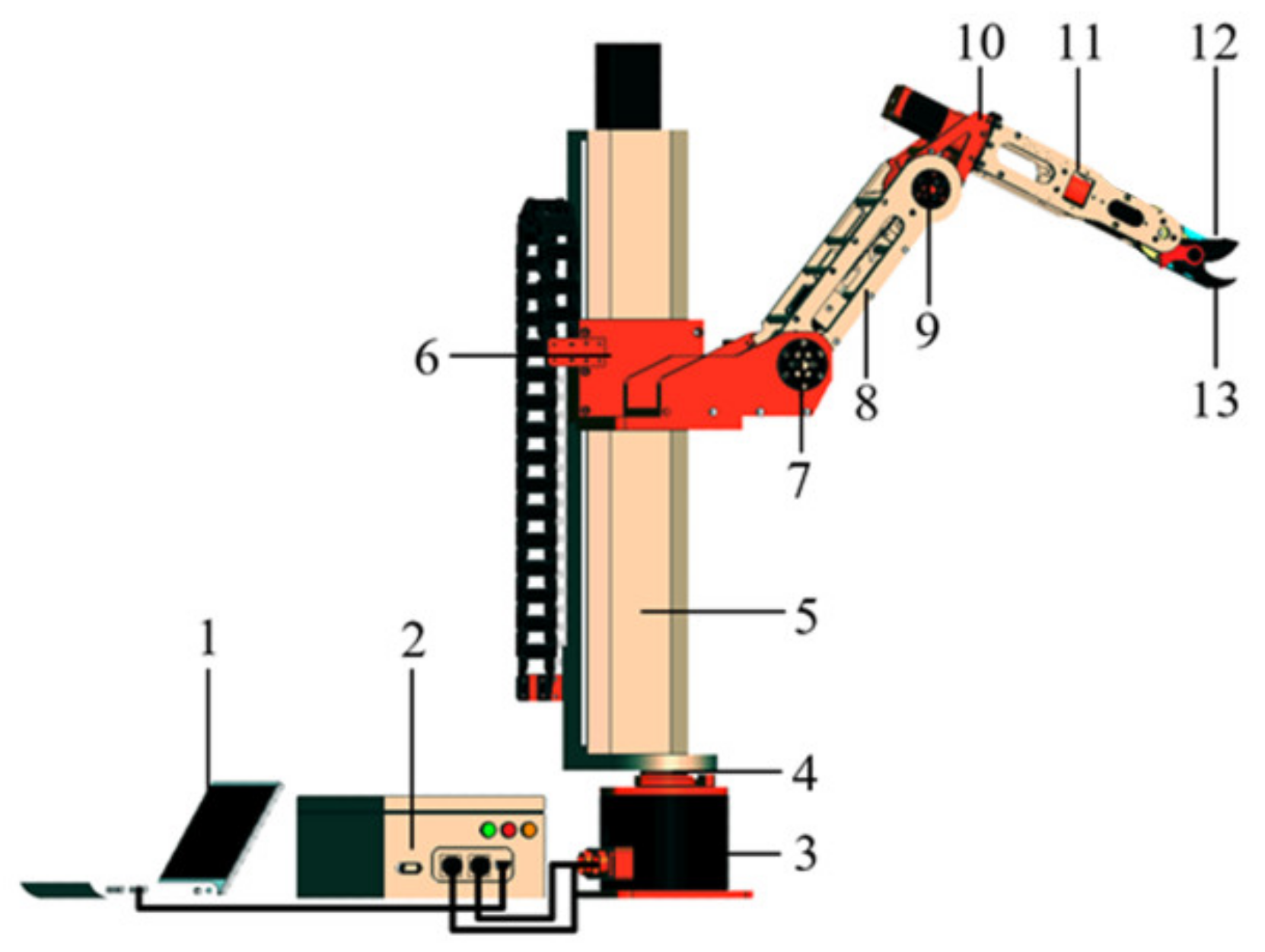
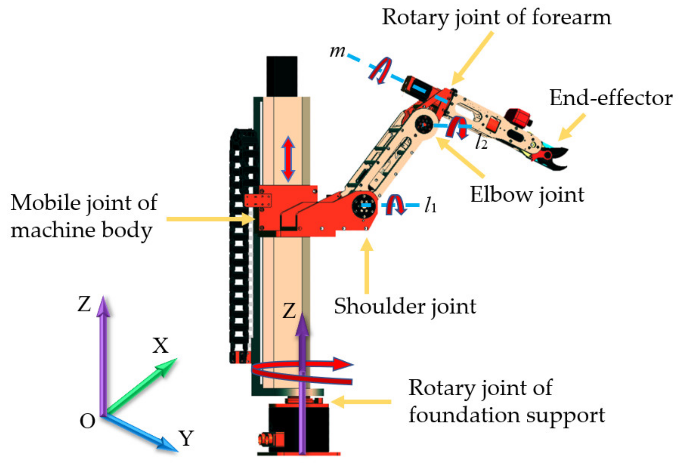
2.1.1. Structure Composition

The body structure of the pruning manipulator for jujube is mainly composed of a machine arm with 5 degrees of freedom (5-DOF), an end-effector, and a control system. Among them, the 5-DOF manipulator is mainly composed of the foundation support, the rotary joint of the foundation support, the machine body, the mobile joint of the machine body, the shoulder joint, the big arm, the elbow joint, the rotary joint of the forearm, and the forearm. The shear end-effector is mainly composed of a moving cutter and a stationary cutter. The control system is mainly composed of a lower control system and an upper man–machine interface. The diagram for the structure of the overall machine is shown in Figure 1.

2.1.2. Working Principle

When the manipulator is working, the upper computer of the control system in the teaching mode obtains the coordinate information of the pruning points for the jujube, according to the experience and knowledge obtained from the jujube farmers, and sends them to the lower computer of the manipulator control system. After the lower controller of the control system receives the location information instruction for the coordinates of the jujube branches that need to be pruned, the motor of each joint of the manipulator arm is controlled to rotate correspondingly, according to the forward and inverse kinematics analysis data, so that the manipulator reaches the target pruning point for pruning. According to the pruning point information recorded in the man–machine teaching mode of the upper computer, the manipulator is controlled to arrive at each target pruning point in turn for pruning. After the pruning of all the pruning branches has been completed, the manipulator is reset.

2.2. The Design of the Mechanical Arm

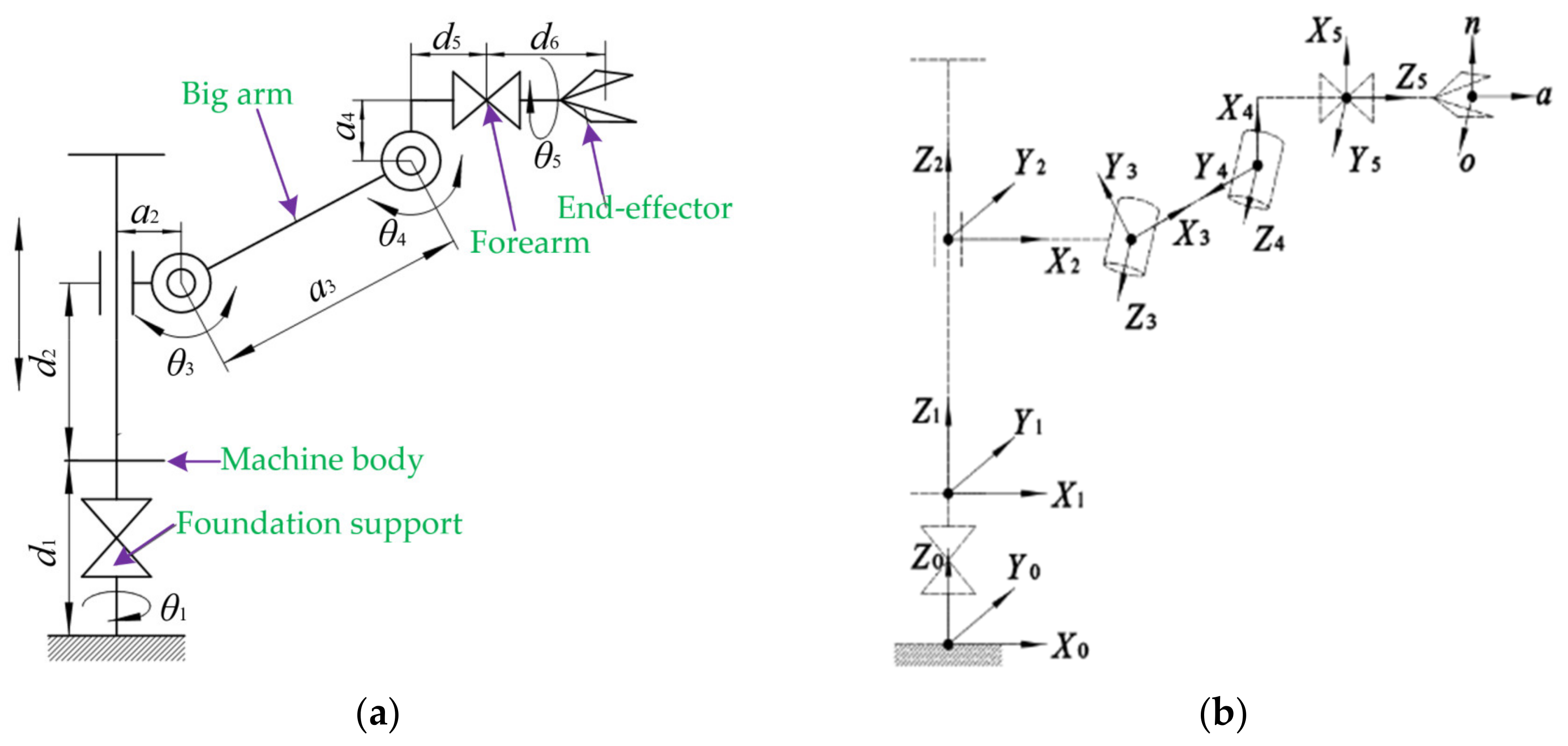
2.2.1. Structure Design

The structural forms of the manipulator mainly include the type of cylindrical coordinate, polar coordinate, rectangular coordinate, and joint coordinate [38]. The joint coordinate manipulator is similar to the human arm, and it has the advantages of a compact structure, flexible movement, large working space, and small occupation area. To simulate the manual pruning process, the joint coordinates were selected to design the pruning manipulator for dwarf and densely planted jujube trees in Xinjiang.
When manually pruning jujube trees, farmers hold pruning scissors through the coordination and cooperation of each joint for pruning. Therefore, when designing the manipulator, three rotating joints were used to determine the position of the target pruned branches. To meet the standards for pruning jujube trees at different heights and branches at different positions, manual pruning needs to be supplemented by a long ladder. Therefore, a movement joint was used to realize the function of moving up and down. In addition, a rotary joint should be added at the end of the manipulator to adjust the attitude of the end-effector to facilitate the pruning. Finally, the 5-DOF mechanical arm can meet the pruning requirements of jujube trees. The designed manipulator consists of four rotary joints and one mobile joint. The four rotary joints are the rotary joint of the foundation support, shoulder, elbow, and forearm, and one mobile joint is the mobile joint of the machine body. The structure and motion direction of each joint for the manipulator are shown in Figure 2. The rotary joint of the foundation support can rotate left and right about the Z axis, and it drives all other joint movements along with it when it turns. The Z axis is perpendicular to the horizontal plane (XOY plane) and moves upwards vertically. The mobile joint of the machine body moves up and down the Z axis, and it drives the rotary joints of the shoulder, elbow, and forearm movement along with it when it moves. The shoulder joint can rotate up and down around the l1 axis, parallel to the horizontal plane (XOY plane). When it rotates, it will drives the elbow and forearm movements together. The elbow joint can rotate up and down about the l2 axis, which is parallel to the l1 axis, and when it moves, it drives the rotation joint of the forearm movement together. The rotation joint of the forearm rotates around the m axis, and the m and l2 axes are perpendicular to each other on different planes. When it moves, it drives the attitude of the end-effector to change.
The rotating joint of the base drives the overall machine to realize the azimuth adjustment and expand the target working area in the horizontal direction (XOY plane). The mobile joint of the body adjusts the manipulator at different heights by moving up and down to expand the target working area in the vertical direction (Z axis), and adapt to the pruning of jujube trees at different heights. The shoulder and elbow joints coordinate with the base joint, and the body joint is used to locate the branches at different positions and adjust the end-effector pruning posture in real time through the forearm rotation joint to adapt to jujube branches with different growth postures.

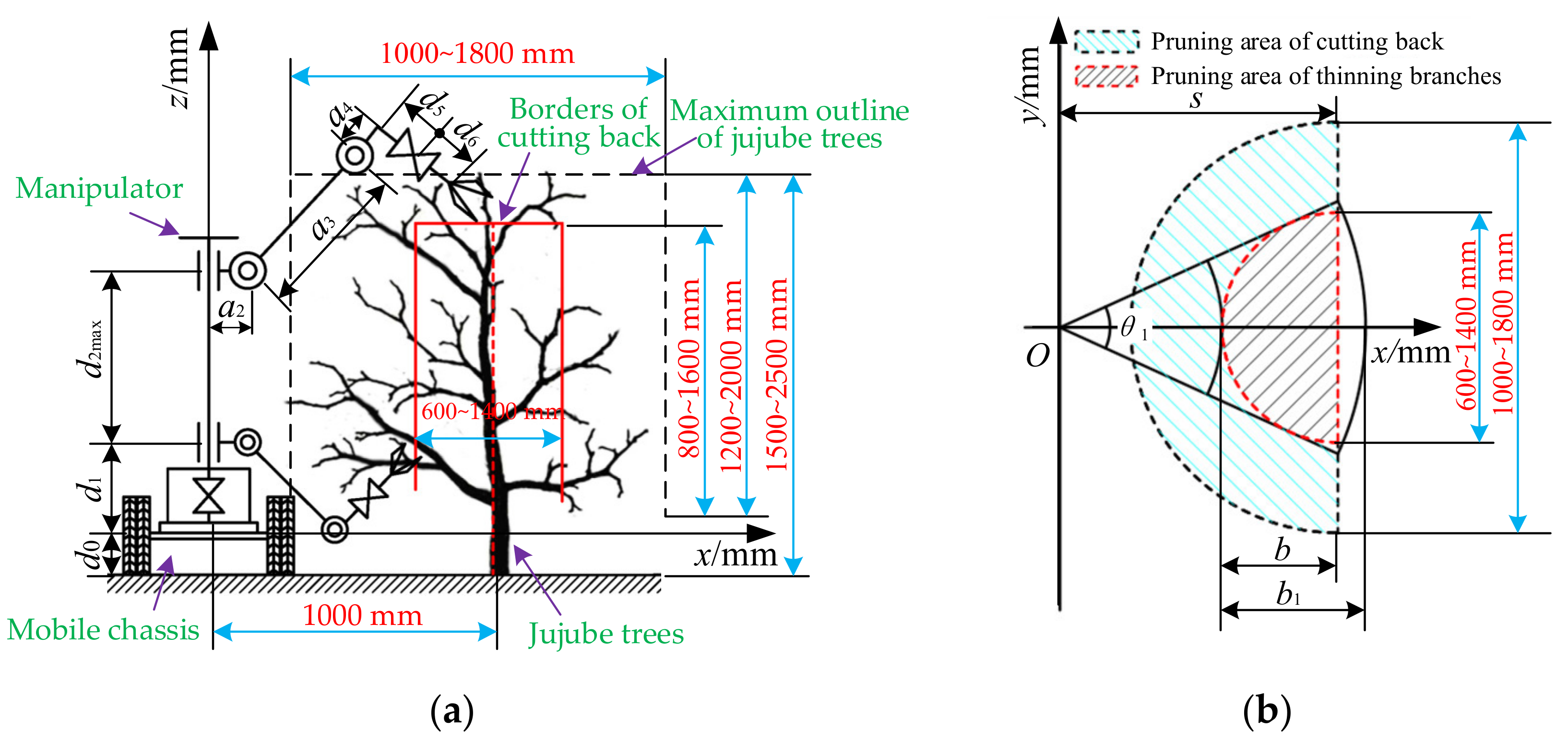
2.2.2. The Parameters Design of the Links Dimension

The link size parameters of each joint for the manipulator were determined by the size information of the jujube tree before and after pruning. Therefore, a field investigation was carried out on jujube trees from 2 to 8 years old in dwarf and densely planted jujube gardens in Xinjiang, and the size information of the jujube trees before and after pruning was obtained by actual measurements. The specific size parameters of the jujube tree growth information are as follows: the row space of jujube trees is generally 3000 mm; the plant space is 800~1000 mm; the height of the jujube trees is generally 1500~2500 mm; the diameter of the canopy is 1000~1800 mm; the height of the canopy is 1200~2000 mm; and the height range of the main branch is 300~500 mm. According to the agronomic requirements of jujube pruning, the height of the canopy after pruning is between 800~1600 mm and the diameter of the canopy is between 600~1400 mm. The area formed by the maximum diameter and height of the jujube canopy is rotated around the direction of its trunk to form a cylinder, which envelopes all of the branches of the jujube tree. In combination with the growth information of the jujube trees, the target pruning space of the jujube trees is analyzed. The manipulator is placed on a mobile chassis with a height of 400 mm, and the horizontal distance between the main stem of the jujube tree and the base of the manipulator is 1000 mm. The analysis for the target pruning space of the manipulator is shown in Figure 3.
The pruning of jujube trees in winter mainly involves shortening and thinning the branches. Additionally, the range of shortening and thinning branches on one side is shown in Figure 3b. When the end of the manipulator reaches the junction of the shortening and thinning branches area, the shortening of the branches can be completed. At the same time, to meet the space requirements of the operation of thinning the branches, the rotation angle of the base should correspond to Equation (1).
θ 1 2 arcsin b m a x / s b m a x = d m a x / 2
where bmax is the maximum radius of the jujube canopy after pruning, mm, dmax is the maximum diameter of the jujube canopy after pruning, mm.
The maximum diameter of the canopy for 2–8-year-old jujube trees after pruning is 1400 mm, which can be substituted into Equation (1) to obtain θ1 ≥ 88.9 degrees. At the same time, when the geometric dimensions of each joint meet Equation (2), the manipulator can complete the unilateral pruning requirements of jujube trees in any horizontal region (xoy). When the rotation angle θ1 of the base is 180 degrees, its travel range is −90~+90 degrees, and the problem of satisfying the three-dimensional space pruning can be simplified as the problem of satisfying the rectangle b1 × h in the longitudinal plane (xoz). When b1 × h is satisfied in the longitudinal plane, the base joint of the manipulator is used to rotate the corresponding angle θ1 around the z axis to achieve the required pruning space.
a 2 + a 3 + d 5 + d 6 s 2 + b m i n 2 a 2 + a 3 s b m i n
where bmin is the minimum radius of the jujube canopy after pruning, mm.
According to the structural layout requirements of the manipulator, when the offset of the shoulder joint a2 is 100 mm and the offset of the forearm rotary joint a4 is 100 mm, the interference between the shoulder joint and forearm rotary joint in the actual assembly and movement can be avoided. To reduce the load arm of the manipulator, the rotary motor of the forearm is arranged at the tail of the forearm, and d5 is 0 mm, which can be obtained by substituting it into Equation (2).
a 3 600 d 6 344
The mechanical arm is a key component of the manipulator. The longer the moment arm of the manipulator, the lower its performance. In the process of movement, if the structure size of the big arm and forearm is larger, the performance of the pruning manipulator is reduced. Therefore, on the premise for meeting the requirements of the pruning space, the design of the big arm and forearm should achieve a compact structure and harmonious proportion. According to Equation (3), the big arm a3 of the mechanical arm designed in this paper is 550 mm, and the forearm d6 is 350 mm. According to the height of the canopy before and after pruning, base d1 is 200 mm, the maximum travel of the machine body d2max of the machine body is 700 mm. By analyzing the pruning space of the manipulator, the dimension parameters of each link of the manipulator are shown in Table 1.

2.3. The Design of the End-Effector

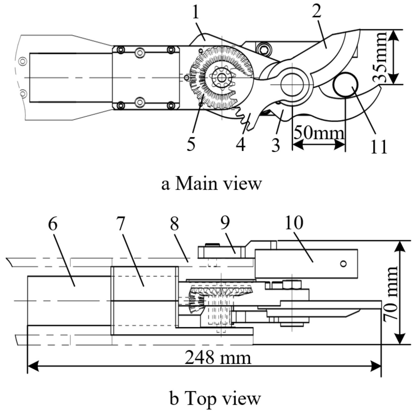
2.3.1. Structure Design

The common pruning methods for fruit trees are shear and saw cutting. As the method of supported pruning, the operation process of shear pruning is stable. In combination with the structural characteristics of the articulated manipulator, the shear structure was selected as the end-effector of the jujube pruning manipulator. It is mainly composed of an executive motor, planetary reducer, gear transmission mechanism, moving cutter, stationary cutter, diagonal photoelectric sensor, mounting plate, and a fixed support. During the operation, the mechanical arm drives the end-effector installed on the forearm to reach the target branch position, and the moving cutter is closed under the action of the executive motor when the diagonal photoelectric sensor detects that the branch has entered the scissor mouth. When the moving and stationary cutters are completely closed, the motor of the end-effector is reversed to make the moving cutter and the stationary cutter open automatically. To enable the pruned branches to effectively enter the cutting mouth of end-effector, the diameter of the pruned jujube branches was 5–20 mm, the opening angle of the moving and fixed cutters was 40 degrees, the maximum vertical distance of the scissor’s mouth was 35 mm, and the distance between the cutting position of the jujube branch and the rotating axis of the moving cutter was 50 mm. The specific structure diagram of the end-effector is shown in Figure 4.

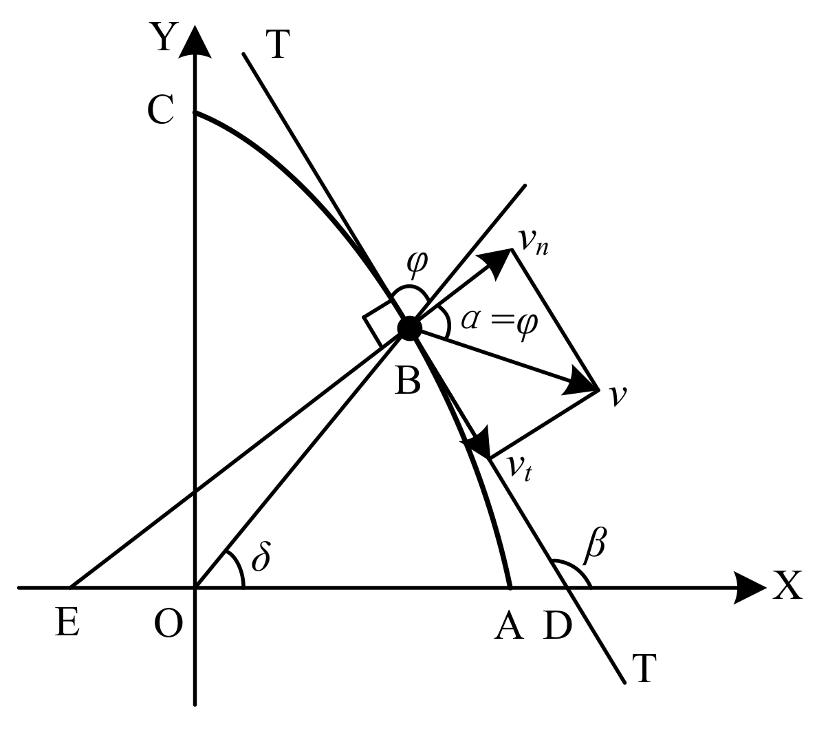
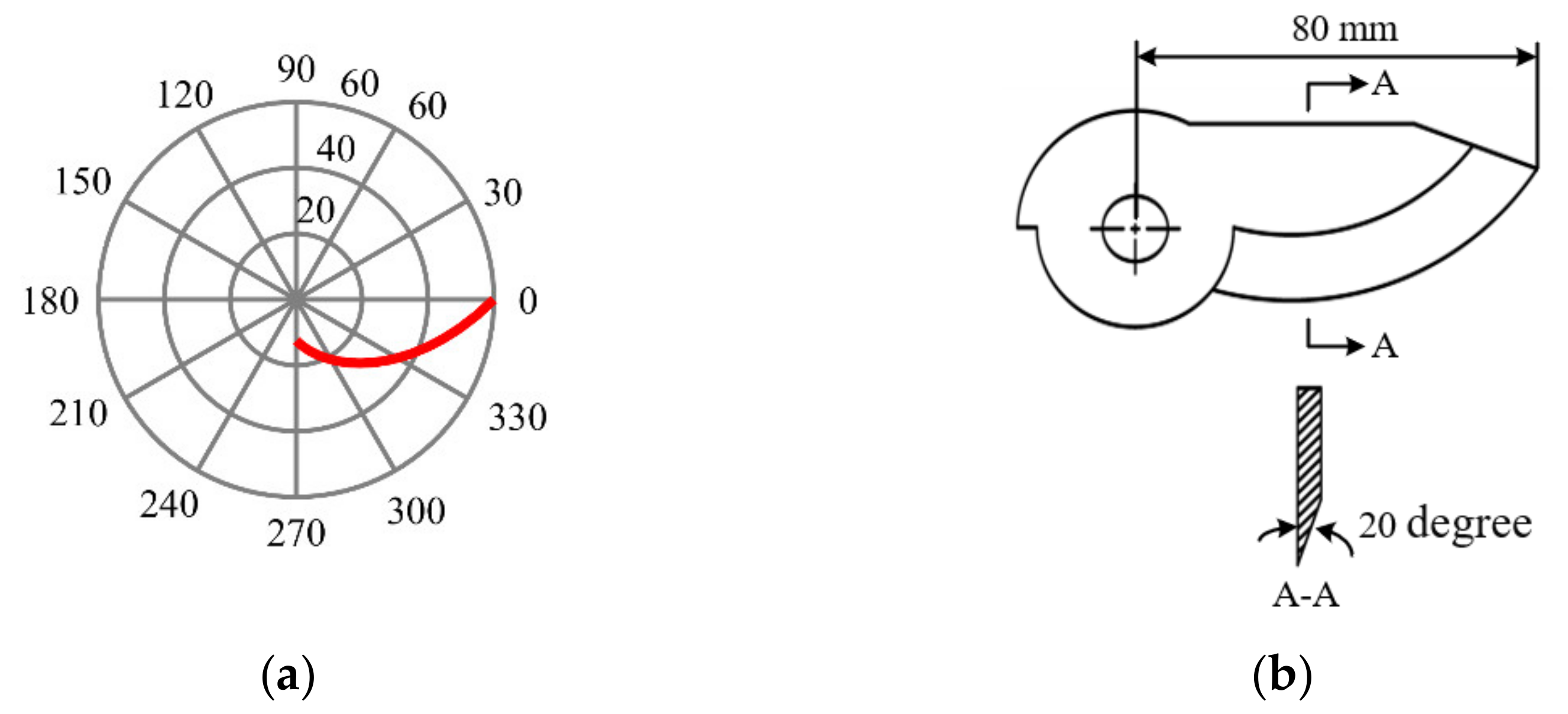
2.3.2. The Design of the Moving Cutter

As a key part of the end-effector, the moving cutter completes the cutting of the branches. To achieve the purpose of saving labor and improving the incision quality, it is necessary to ensure that the cutting angle α of each cutting edge point is equal to the friction angle φ between the moving cutter and the branch during the cutting process. Therefore, the design of the cutting edge curve can achieve the stable and sliding pruning of the jujube branches.
The moving cutter rotated around the hinge point O to shear the jujube branch during the operation. Suppose the blade curve is A B C ^ , the cutting angle α   of any point on the curve is equal to the friction angle φ, and the hinge point O is taken as the origin of the coordinates; a coordinate system is established to analyze the blade curve of the moving cutter, as shown in Figure 5.
According to the geometric relation of ∆OBD, β = δ + φ. There are:
tan β = tan δ + tan φ 1 tan δ · tan φ
where tan β = d y d x , tan δ = y x = u . Substitute them into Equation (4) to obtain:
1 u tan φ tan φ + u 2   tan φ d u = 1 x d x
Integrate both sides of Equation (5) to obtain:
1 2 ln x 2 + y 2 = 1 tan φ a r c t a n y x + C
By substituting x = ρ · cos δ , y = ρ · sin δ , and substitute them into Equation (6); the polar coordinate equation for the blade curve of the moving cutter is:
ρ = C e δ tan φ
where ρ is the polar diameter, mm; δ is the polar angle; and C is the integration constant.
According to Equation (7), when the blade curve of the moving cutter is a logarithmic spiral, stable and sliding pruning can be realized. When the polar angle changes from δ1 to δ2, the required cutting edge arc length l is the following:
l = δ 2 δ 1 d l = δ 2 δ 1 ρ 1 2 + ρ 2 2   d δ = ρ 2 ρ 1 cos φ
According to Equation (8), ρ2ρ1d must be satisfied when cutting the jujube branch with diameter d. Additionally, the actual diameter range of pruning the jujube branches is 5–20 mm, so the length of the designed moving cutter is 80 mm. According to the relevant design research of the cutting tools, the slide angle was designed to be 35 degrees and the edge inclination angle was 20 degrees. Figure 6a shows the blade curve of the moving cutter established by MATLAB, and Figure 6b shows the structure of the moving cutter designed by using the blade curve.

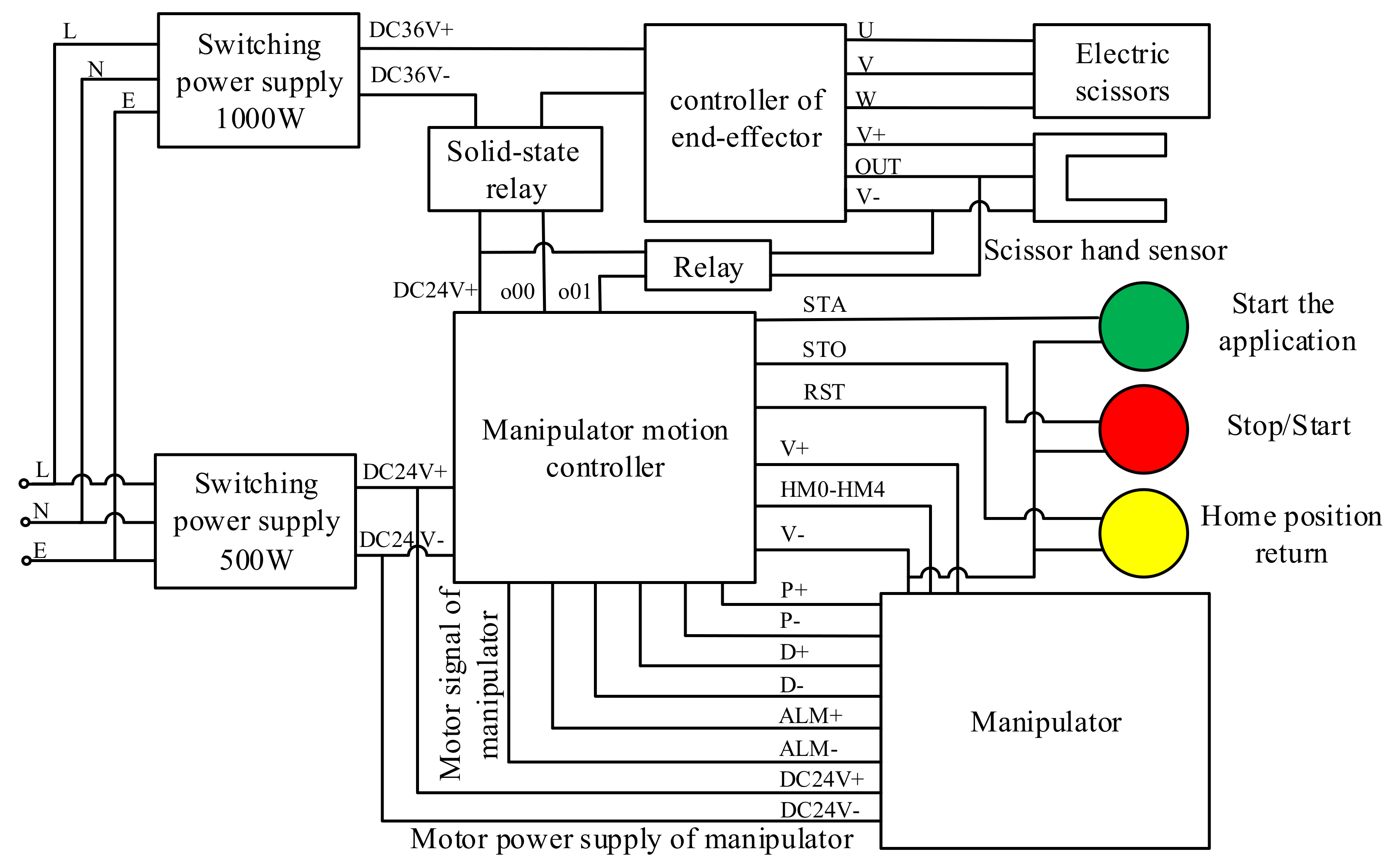
2.4. The Design of the Control System

The design and construction of the control system for the jujube pruning manipulator are very important for its pruning function. The main function of the control system of the jujube pruning manipulator designed in this paper is to realize the delivery, processing, and execution of the control instructions, so as to realize the data communication between the upper and lower computers. The diagram for the overall control scheme of the jujube pruning manipulator is shown in Figure 7.
The control system of the manipulator adopts a two-layer structure control, including the upper and lower computers. The lower computer control system adopts a six-axis off-line motion controller (YJ-CTRL-A601; Shenzhen Yijia Technology Co., Ltd.; Shenzhen; China). The driving motor of each joint is an integrated closed-loop stepper motor (ESS60-P; Shenzhen YAKO Automation Technology Co., Ltd.; Shenzhen; China). The controller is connected to each joint motor of the manipulator through the signal output port, pulse output port, direction port, servo enable port, servo alarm, and alarm clearing port of the encoder, and the driver of each joint motor is controlled by the sending direction and pulse signal. In addition, the motion controller is connected to the solid-state relay by the switching output. The relay signal is used as the input signal of the end-effector controller to control the moving cutter. Finally, the switch signal output by the sensor of the end-effector controls the power-on or power-off of the relay coil to play the role of system protection or automatic control. The diagram for the electrical schematic of the jujube pruning manipulator is shown in Figure 8.
The upper computer adopts a PC machine (Lenovo Y9000P; Lenovo Group; Beijing; China), of which the basic frequency is 2.30 GHz, the development environment is Visual Studio, and the development language is C#. The lower computer communicates with the upper computer through a serial port, for which the serial port communication protocol is RS232, the serial port parameter’s baud rate is 115,200, the data bit is 8, and the stop bit is 1.

2.5. The Kinematics Analysis of the Manipulator

Based on the kinematics analysis of the manipulator designed in this paper, the relationship between the pose of the end-effector and the joint variables of the manipulator was established, and the workspace simulation was carried out based on the kinematics model to verify whether the workspace of the manipulator met the requirements of the pruning space. The coordinate system of the link of the jujube pruning manipulator is shown in Figure 9. The parameters of the link of the jujube pruning manipulator are shown in Table 2.

2.5.1. Forward Kinematics Analysis

The DH parameter method [11,39] was used for the kinematic analysis, and a kinematic model of the manipulator was established to describe the relative position and attitude among the coordinate systems. According to the kinematics theory of the robot, the general formula T i i 1 of the transformation matrix under the DH parameters of the adjacent link of the manipulator is:
T i i 1 = cos θ i sin θ i 0 a i 1 sin θ i cos α i 1 cos θ i cos α i 1 sin α i 1 d i sin α i 1 sin θ i sin α i 1 cos θ i sin α i 1 cos α i 1 d i cos α i 1 0 0 0 1
where θ i is the joint angle, degree; d i is the horizontal distance, mm; a i 1 is the distance of the common normal, i.e., the length of the rod, mm; and a i 1 is the torsion angle, degree.
According to Equation (9) and the parameters of the link presented in Table 2, the transformation matrix T 6 0 for the end pose of the jujube pruning manipulator can be obtained:
T 6 0 = T 1 0 T 2 1 T 3 2 T 4 3 T 5 4 T 6 5 = n x o x a x p x n y o y a y p y n z o z a z p z 0 0 0 1
where
n x = c 1 c 5 c 3 c 4 s 3 s 4 + s 1 s 5 n y = s 1 c 5 c 3 c 4 s 3 s 4 c 1 s 5 n z = c 5 c 3 s 4 + s 3 c 4 o x = s 1 c 5 c 1 s 5 c 3 s 4 s 3 s 4 o y = s 1 s 5 c 3 c 4 s 3 s 4 c 1 c 5 o z = s 5 c 3 c 4 + s 3 c 4 a x = c 1 c 3 s 4 + s 3 c 4 a y = s 1 c 3 s 4 + s 3 c 4 a z = s 3 s 4 c 3 c 4 p x = c 1 [ a 2 + a 3 c 3 + a 4 c 3 c 4 s 3 s 4 + d 5 + d 6 c 3 s 4 + s 3 c 4 p y = s 1 [ a 2 + a 3 c 3 + a 4 c 3 c 4 s 3 s 4 + d 5 + d 6 c 3 s 4 + s 3 c 4 p z = a 3 s 3 + a 4 c 3 s 4 + s 3 c 4 + d 1 + d 2 + d 5 + d 6 s 3 s 4 c 3 c 4
In Equation (11), ci = cosθi, si = sinθi, where i is 1, 3, 4, and 5, respectively. The same is expressed below.
The transformation matrix T 6 0 represented by Equation (10), describes the pose of the base coordinate system {0} relative to the end-effector coordinate system {6} of the pruning manipulator. To test the correctness of the model T 6 0 , the initial positions ( θ 1 = 0   degree , θ 3 = 90   degree , θ 4 = 0   degree , θ 5 = 0   degree ) of the manipulator were obtained for checking and calculation; substituting them into Equation (11), the result of calculating the arm transformation matrix T 6 0 is:
T 6 0 I n i t i a l   p o s i t i o n = 0 0 1 450 0 1 0 0 1 0 0 650 0 0 0 1
The test results of Equation (12) are consistent with the initial position parameters of the designed manipulator, indicating that the established mathematical model of the manipulator kinematics is correct.

2.5.2. Inverse Kinematic Analysis

Before the manipulator is driven to the desired position, all the joint variables related to the position must be obtained. Therefore, it is necessary to carry out the inverse kinematics analysis of the manipulator.
The desired pose coordinate of the end-effector of the manipulator is assumed as [n, o, a, p]. Firstly, multiply T 1 0 1 at both sides of Equation (10) by the inverse transformation method. After simplification, it can be determined that T 1 0 1 T 6 0 = T 2 1 T 3 2 T 4 3 T 5 4 T 6 5 . According to the equal elements of the matrices at both sides, it can be determined that c 1 × p y = s 1 × c 1 × p x . Finally, the rotation angle of the base joint is shown in Equation (13):
θ 1 = a r c t a n p y p x
Similarly, multiply T 2 1 1 ,   T 3 2 1 ,   T 4 3 1 ,   T 5 4 1 ,   T 6 5 1 at both sides of Equation (12), and, according to the elements at both sides, which are equal, the general expressions of the revolute joint variables θ 3 ,   θ 4 ,   θ 5 are obtained, as shown in Equation (14)~(16):
θ 3 = a r c t a n t 2 d 5 + d 6 a z a 4 c 1 a x + s 1 a y t 1 d 5 + d 6 c 1 a x + s 1 a y + a 4 a z
θ 4 = a r c t a n a 4 c 3 t 2 s 3 t 1 + d 5 + d 6 s 3 t 2 + c 3 t 1 a 2 a 4 s 3 t 2 c 3 t 1 a 3 d 5 + d 6 c 3 t 2 + s 3 t 1
θ 5 = a r c t a n n x · sin θ 1 n y · cos θ 1 o x · sin θ 1 o y · cos θ 1
where t 1 = c 1 p x + s 1 p y a 2 , t 2 = p z d 1 d 2 .
In conclusion, the DH parameter method was used to establish the theoretical model of the manipulator kinematics, and the relative position and pose relationship between the coordinate systems of each joint were obtained. Meanwhile, the inverse kinematic analysis of the manipulator was carried out to obtain the general expressions for the joint angles of the manipulator, which provides the theoretical basis for the simulation analysis of the manipulator workspace.

3. The Performance Test Method of the Manipulator

To further verify whether the designed manipulator meets the performance requirements of jujube pruning, the performance test of the jujube pruning manipulator prototype was carried out, based on high-speed camera technology [40,41,42].

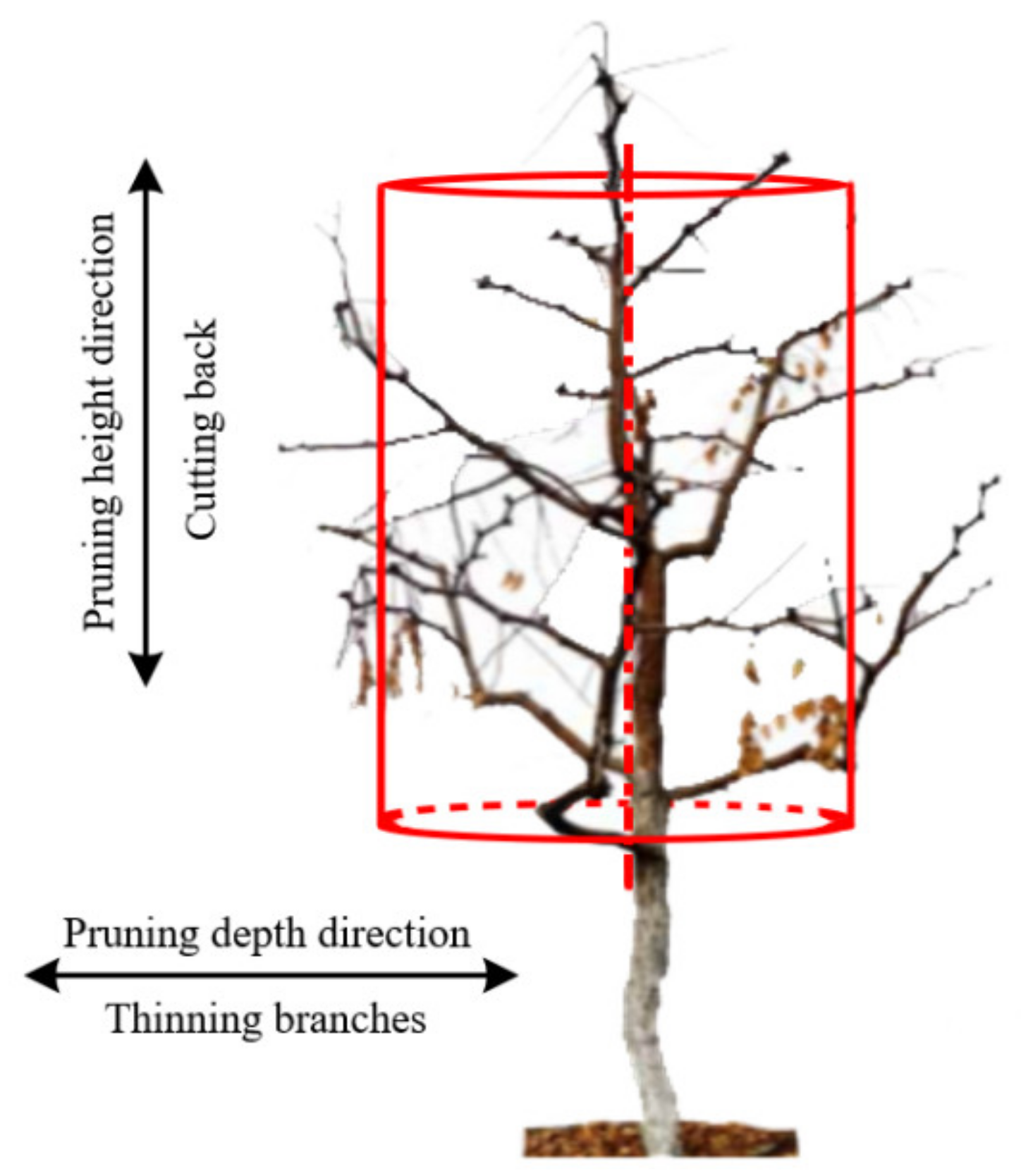
3.1. The Analysis of the Agronomic Pruning Point for Jujube Trees

Jujube pruning agronomy mainly consists of cutting back and thinning the branches. Cutting back mainly consists of cutting off part of the lateral branches of the current year’s growth along the height of the jujube trees, which can inhibit the excessive growth of the lateral branches and promote the main branches to produce flowers and fruit. The thinning of the branches mainly entails the cutting off of the dense or dead branches along the depth of the jujube trees, which can improve ventilation and light, and promote the rejuvenation of dead branches. By analyzing the process of using the manipulator to prune the jujube trees, it can be concluded that the manipulator needs to reach the different heights of the jujube tree canopy for pruning when cutting back the branches, and the manipulator needs to complete the pruning of jujube branches at different depths when thinning the branches. The schematic diagram of the agronomic pruning analysis for a jujube tree is shown in Figure 10. In the actual operation, the manipulator is installed on the mobile chassis. In order to be convenient for analysis, the jujube tree height corresponding to the installation height of the manipulator base is taken as zero. A field investigation was carried out on the growth information of the jujube trees before and after pruning; it was found that the cutting back points were mainly distributed in the range of 200~1000 mm in the height direction of the jujube trees, and the points of the thinning branches were mainly distributed in the range of 100~700 mm, in the depth direction of the jujube trees.

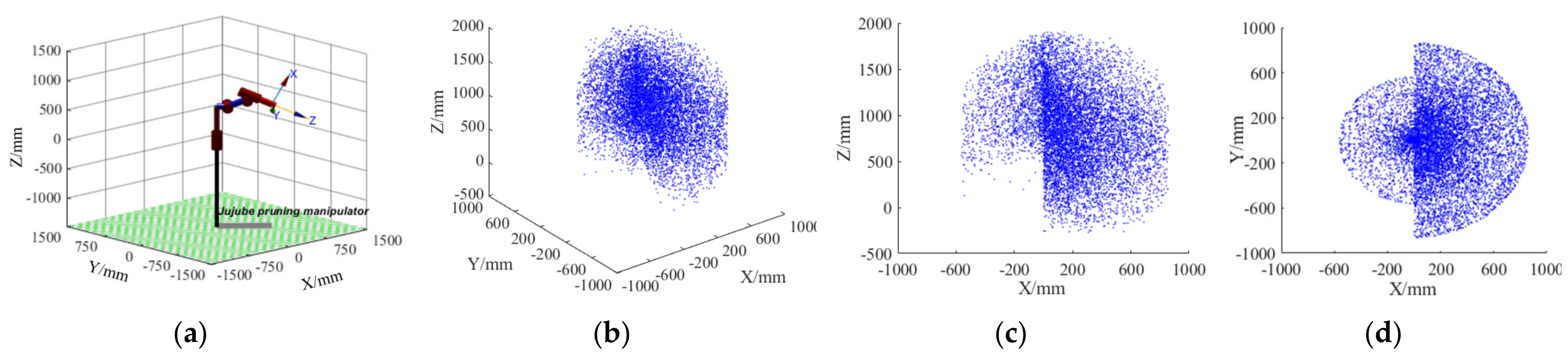
3.2. The Workspace Simulation of the Manipulator

Based on the MATLAB Robotics Toolbox, a 3D mathematical simulation model of the jujube pruning manipulator was established. The Monte Carlo method [43] was used to simulate the workspace of the manipulator to verify whether the theoretical design of the manipulator met the requirements of the jujube pruning space. According to the kinematic theoretical analysis of the manipulator, in combination with the parameters and variable ranges of each joint size of the manipulator presented in Table 1 and Table 2, the Rand function in MATLAB was used to program the manipulator workspace for the calculation and simulation. The random values of each joint variable generated by the Rand function are shown in Equation (17):
θ i = θ i m i n + θ i m a x θ i m i n × R a n d N , 1
where θ i m i n is the minimum value of the angle range of joint i, degree; θ i m a x is the maximum angle range of joint i, degree; and N is the number of cycles, N = 10,000.

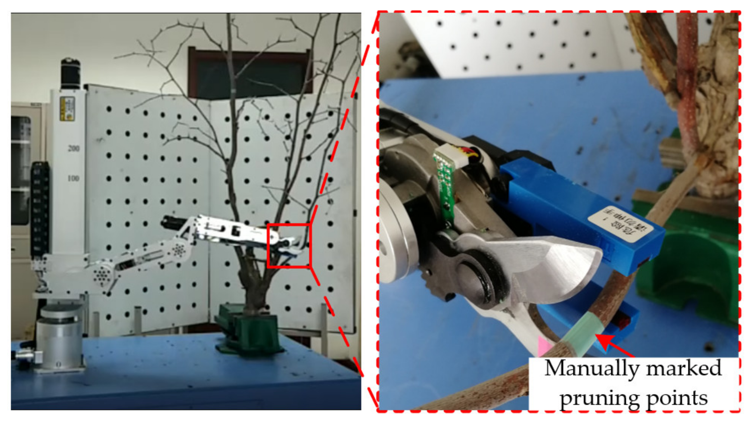
3.3. The Platform Construction and Test of the Prototype

The self-made prototype for the jujube pruning manipulator was used to build its performance test platform, as shown in Figure 11. The test results were recorded by a 3D high-speed camera system. The test equipment mainly includes a pruning manipulator prototype, a 3D high-speed camera (FASTECIMAGING-TS4; Fastec Imaging Corporation; San Diego, CA, USA), a graduated scale (accuracy: 1 mm), and a calibration plate.

3.3.1. The Scheme for the Positioning Accuracy Test

The end-effector was driven by the manipulator to move to the target pruning point of the branch when pruning the jujube trees, and the branches triggered sensors to complete the pruning operation. The positioning accuracy of the end-effector to the pruning point is one of the key factors for completing the pruning operation. Therefore, the positioning error of the end for the manipulator was taken as the evaluation index to verify the positioning accuracy of the manipulator moving to the pruning points of the jujube trees. The calculation of the positioning error is shown in Equation (18):
D = X X 0 2 + Y Y 0 2 + Z Z 0 2
where P0(X0,Y0,Z0) are the theoretical coordinates of the pruning points, mm, and P(X,Y,Z) are the measured coordinates of the pruning points, mm.
By taking the base of the manipulator as the origin, the positions for the end-effector of the manipulator to the 9 pruning points with the horizontal distance of 600 mm and the height of 200~1000 mm were recorded, and the positioning accuracy was tested. Similarly, the positions of the end of the manipulator to the 5 pruning points with equal spacing ranging from 100~700 mm in the depth direction were recorded, and the positioning accuracy of the end-effector to the pruning points with different depths was tested. The video data analysis software ProAnalyst was used to analyze the test results for the positioning accuracy of the manipulator end-effector. Firstly, the manipulator in the video was calibrated. The ruler placed in advance on the manipulator was marked, and the actual size of the ruler was input in the software; then, the manipulator in the video was restored to the actual size after calibration. Secondly, the center position of the base of the manipulator in the video data analysis software was set as the base coordinate system of the manipulator. Thirdly, the position of the end-effector in the video data analysis software was marked as the tracking point. The motion track of the manipulator along different height directions and different depth directions was automatically tracked. Finally, the coordinates for the tracked trajectory of the manipulator end-effector in the video data analysis software were output and recorded.

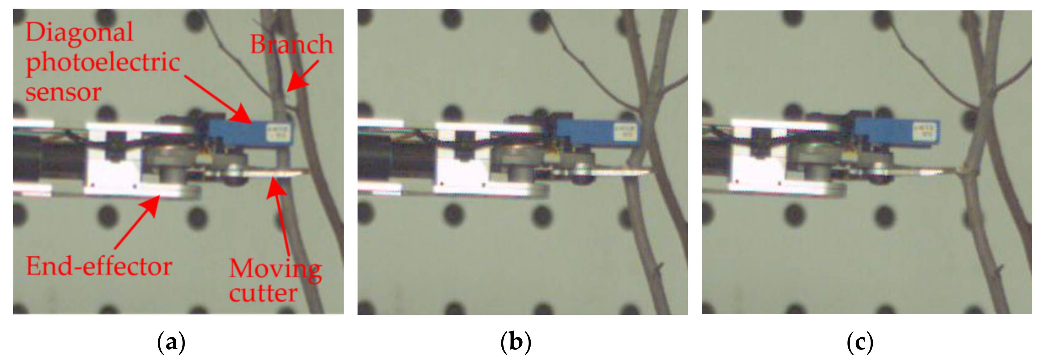
3.3.2. The Scheme for the Pruning Test

The test subjects were five two-year-old jujube trees from the Science and Technology Park of Shihezi University. The average height of the jujube trees was 1.8 m, and the average width of the canopy was 1.4 m. The jujube tree was fixed on the performance test platform of the manipulator to conduct the pruning test, as shown in Figure 12.
The specific operational procedures of the jujube pruning test are as follows: firstly, according to the artificial pruning of the jujube agronomic knowledge and the experience of the jujube farmers, the branches that needed to be cut and the location of the pruning points were identified manually, and each pruning point was marked with green tape. Secondly, the manipulator was set to teaching mode (when the manipulator was in teaching mode, the sensor of the end-effector was in the closed state, and the pruning function of the end-effector could not be triggered when the manipulator reached the pruning point), and the manipulator was controlled manually to reach the pruning point of the jujube tree. Additionally, the coordinate information of the current pruning point was obtained and recorded by the upper computer. The above operations were repeated to obtain and record the coordinate information of each pruning point. Finally, the manipulator was reset to the initial state and set to working mode (when the manipulator was in working mode, the sensor of the end-effector was in an open state. When the manipulator reached the pruning point of the jujube tree, the branch entered the detection area of the sensor, which could trigger the pruning function of the end-effector). The coordinates of the pruning point were manually input into the upper computer, the manipulator was controlled to automatically reach the pruning point of the jujube tree, and the pruning test was carried out. The 3D high-speed camera was used to record the real-time video data of the motion position and pose for the manipulator in the pruning process. The video data analysis software ProAnalyst was used to extract the pruning time and judge the effect of pruning.
The main purpose of the pruning manipulator is to complete the pruning task in a short period of time. Therefore, the success rate of pruning R and the pruning time T are taken as the evaluation indexes of the pruning performance for the manipulator. The success rate of pruning (R) and the pruning time (T) were calculated as follows:
R = i = 1 n L i L × 100 %
T = i = 1 n T i
where ∑L is the total pruning time of a single jujube tree; n is the number of successful pruning attempts of a single jujube tree; and Ti is the time taken to complete the i-th pruning, min.

4. Results and Discussion

4.1. The Simulation Results and Analysis of the Manipulator Workspace

The simulation results of the manipulator workspace are presented in Figure 13. The workspace of the manipulator is −600~800 mm in the X direction, −800~800 mm in the Y direction, and −200~1800 mm in the Z direction. Additionally, the pruning points are more dense in the range of 0~600 mm in the X direction, −600~600 mm in the Y direction, and 0~1700 mm in the Z direction. The simulation results show that the geometric size of the jujube pruning manipulator can meet the requirements of the pruning space of the jujube trees in the dwarf and densely planted jujube garden.

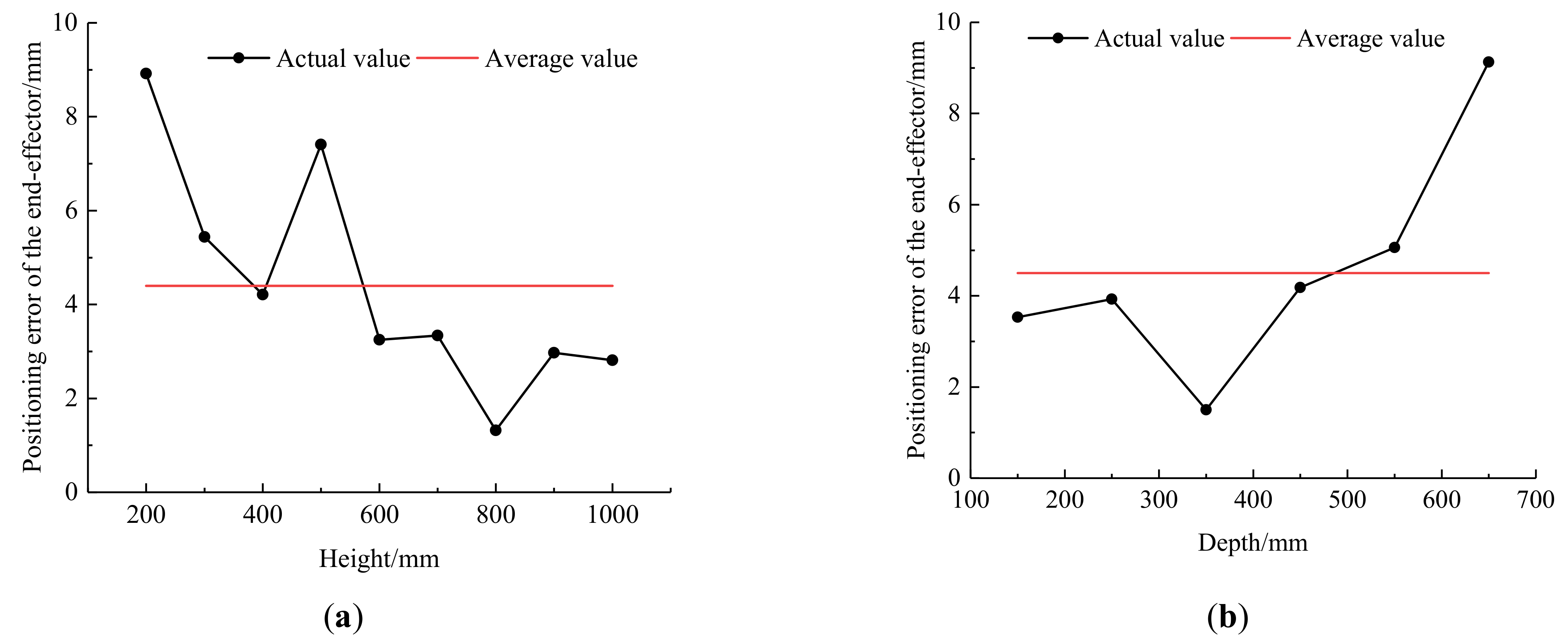
4.2. The Results and Discussion of the Positioning Accuracy

The test results for the positioning error of the manipulator at different pruning points are presented in Table 3. The schematic diagram of the positioning error trend for the manipulator end-effector is shown in Figure 14.
Table 3 and Figure 14 show that, in the height directions, the positioning error of the end-effector tends to decrease as the height increases when the manipulator moves from the initial position (450, 0, 650) to different height positions (600, 0, 200~1000), and the average error value is 4.4 mm. The maximum error occurs at the lowest position (Z = 200 mm), which is 8.92 mm. The main reason for this phenomenon is that, when the manipulator end-effector moves from the initial position to different heights below 650 mm, the moment arm of the machine arm gradually increases with the decrease in the height of the pruning position, and the direction of the manipulator movement is consistent with the gravity direction of the center-of-mass gravity of the manipulator body, resulting in the positioning error of the end-effector increasing with the decrease in the height of the pruning position. When the manipulator is at the lowest position (Z = 200 mm), the motion inertia force reaches its maximum, resulting in the maximum positioning error occurring in this position. When the end-effector moves from the initial position to different heights above 650 mm, the moment arm of the machine arm gradually increases with the increase in the height of the pruning position. However, the direction of the manipulator movement is opposite to the gravity direction of the center-of-mass gravity of the manipulator body, resulting in the positioning error of the end-effector decreasing with the increase in the height of the pruning position. Therefore, the positioning error of the end-effector tends to decrease as the height of the pruning position increases.
In the depth directions, when the manipulator moves from the initial position (450, 0, 650) to different depth positions (150~650, 0, 600), the positioning error of the end-effector tends to increase as the depth of the pruning position increases, and the average error value is 4.5 mm. The maximum positioning error occurs at the farthest position of pruning point (X = 650 mm), which is 9.13 mm. The main reason for this phenomenon is that the moment arm of the machine arm increases as the moving distance of the manipulator end-effector increases in the direction of the depth. Therefore, the positioning error of the end-effector increases with the increase in the depth of the pruning position.
In conclusion, the positioning errors of the end-effector of the pruning manipulator at different heights and depths are all less than 10 mm. There are two main reasons for the positioning error of the manipulator in the process of the test. On the one hand, there are errors in the manufacturing and assembly of all the parts of the manipulator, and a mechanical vibration occurs in the process of operation. On the other hand, the center of gravity for the machine arm changes in real time during the operation of the manipulator. In the follow-up study, the positioning error is improved by improving the manufacturing and assembly accuracy of the manipulator parts and further optimizing the control system.

4.3. The Results and Discussion of the Pruning Test

The results of the pruning test are shown in Table 4. Due to the unstructured natural growth of jujube tree canopy, the number of branches, which were identified to be pruned, and the location of the pruning point vary from tree to tree. Therefore, the number and position of the pruning points were different for each jujube tree in the test. Among them, when the first jujube tree was pruned, a total of 36 pruning points were determined, and 33 points were successfully pruned. The success rate of pruning was 91.67%, which was the highest among the 5 jujube trees. Additionally, the pruning time was about 29.3 min. When the 5th jujube tree was pruned, 23 of the 27 pruning points were successfully pruned, and the success rate of a single jujube tree was 85.16%, which was the lowest among the 5 jujube trees. The pruning time was about 25.6 min.
A total of 156 pruning points were determined in the 5 tests, and the results show that 139 points were successfully pruned. The average success rate of pruning a single jujube tree was about 89.10%, and the average time was about 27.7 min. Additionally, the manipulator ran smoothly in each pruning process. The test verified the reasonableness and feasibility of the designed pruning manipulator.
Figure 15 shows the whole process of the failed pruning of the manipulator. The main reason for the failure was that the branches deviated from the sensor detection area in the pruning process of the moving cutter. Figure 16 shows the whole process of the successful pruning performed by the manipulator. The main reason for the success was the branches in the pruning process of the moving cutter; the branches are always in the sensor detection area. To summarize, the remote and small branches on the side of the jujube tree were easy to fail pruning in the test. The main reason is that the mechanical arm is in a state when the manipulator runs lateral to the jujube trees in a remote location. According to the results of the positioning accuracy of the positioning error of the manipulator, the end-effector is large at this time. In addition, small branches are easy to bend when touching the moving cutter, leading to branches deviating from the sensor detection area. The next study is to optimize and improve the sensitivity and detection range of the end-effector, so that the improved sensor can effectively avoid the jujube branches from breaking away from the detection area after bending.
At present, there are many researches on the robot technology in agricultural fields, such as orchard picking, plant protection, and fruit-tree pruning. For different agricultural production links and different operation objects, each form of research has put forward different strategies. In many cases, it is difficult to compare and evaluate the performance of different machines, because the operating objects and operating conditions greatly vary. At present, typical researches in the field of orchard pruning, such as the grape-pruning robot designed by Botterill et al. [26], the apple-tree pruning robot designed by Zahid et al. [27,28,29], the loquat-pruning robot designed by Huang et al. [35,36], and the high-branch pruning manipulator designed by Wu et al. [37], are still in the initial stage of research. Because the growth information and agronomic pruning requirements of jujube trees are different from other fruit trees, it is necessary to design special pruning equipment for jujube trees, according to the growth characteristics and agronomic pruning requirements of dwarf and densely planted jujube trees in Xinjiang. Fu et al. developed a shaping and pruning machine for dwarf and densely planted jujube trees [20]. This machine can realize the rapid shortening pruning function of large-scale jujube trees, with a high pruning efficiency. However, it cannot realize the thinning branch pruning function of jujube trees, and the internal ventilation and light transmission of jujube trees after pruning are poor. Therefore, on the basis of this research, we propose the manipulator pruning jujube tree program. According to the characteristics of the artificial pruning of jujube trees, a 5-DOF jujube pruning manipulator was designed by choosing a joint manipulator structure to realize the function of the selective pruning of jujube trees.

5. Conclusions and Future Work

A 5-DOF pruning manipulator was designed, and the relative position and attitude of each coordinate system were obtained by establishing the theoretical model of manipulator kinematics. The workspace of the manipulator was obtained through the simulation analysis of the workspace of the manipulator (−600~800 mm in the X direction, −800~800 mm in the Y direction, and −200~1800 mm in the Z direction). It was verified that the geometric size of the manipulator met the requirements of the pruning space of jujube trees in the dwarf and densely planted jujube garden. Finally, a prototype manipulator was developed, and the positioning accuracy test of the end-effector and pruning performance test of the manipulator were carried out, based on high-speed camera technology. The results show that the positioning errors of the manipulator at different pruning points were all less than 10 mm, the average pruning success rate of the manipulator was about 89.10%, and the average pruning time of a single jujube tree was 27.7 min. It was verified that the structure and control system of the pruning manipulator was reasonable and feasible. This study can provide a theoretical basis and technical support for the intelligent pruning of a jujube garden.
This paper mainly studied the mechanical structure and control system of the manipulator, but there are still pruning failures in the pruning tests of jujube trees. The aim of the subsequent study is to optimize the structure of the manipulator body and improve the control system to further improve the success rate of manipulator pruning. At the same time, the machine vision system will be equipped on the manipulator to realize the intelligent recognition and positioning of pruning points. Additionally, the mobile chassis and manipulator were integrated to carry out the experiment research of jujube-tree pruning in a natural environment, so as to realize the intelligent pruning of a jujube garden.

Author Contributions

Conceptualization, B.Z. and X.C.; Data curation, B.Z. and H.Z.; Formal analysis, B.Z. and C.S.; Funding acquisition, W.F. and C.S.; Investigation, B.Z., H.Z. and C.S.; Methodology, B.Z. and X.C.; Project administration, W.F. and C.S.; Resources, W.F. and C.S.; Software, B.Z. and H.Z.; Supervision, W.F.; Validation, B.Z., W.F., X.C., H.Z. and C.S.; Visualization, B.Z. and C.S.; Writing—original draft, B.Z. and H.Z.; Writing—review and editing, B.Z. and W.F. All authors have read and agreed to the published version of the manuscript.

Funding

This work was supported by the National Natural Science Foundation of China (NSFC), No. 51765058, Regional Innovation Guidance Project of the Xinjiang Production and Construction Group (No.2021BB020), Scientific and Technological Innovation Talents Program of the Xinjiang Production and Construction Group (No.2020CB008).

Institutional Review Board Statement

Not applicable.

Informed Consent Statement

Not applicable.

Data Availability Statement

The data presented in this study are available on-demand from the first author at ([email protected]).

Acknowledgments

The authors would like to thank their schools and colleges, as well as the funding of the project. All support and assistance are sincerely appreciated. Additionally, we sincerely appreciate the work of the editor and the reviewers of the present paper.

Conflicts of Interest

The authors declare no conflict of interest.

References

  1. Zhang, B.; Fu, W.; Wang, X.F.; Lou, Z.X.; Liu, Y.D.; Fu, Y.X.; Chen, Y.Y. Bench test and parameter optimization of jujube pruning tools. IAEJ 2020, 29, 58–68. [Google Scholar]
  2. Fu, W.; Zhang, Z.Y.; Ding, K.; Cao, W.B.; Kan, Z.; Pan, J.B.; Liu, Y.D. Design and test of 4ZZ-4A2 full-hydraulic self-propelled jujube harvester. Int. J. Agric. Biol. Eng. 2018, 11, 104–110. [Google Scholar] [CrossRef]
  3. Gao, W.H.; Han, R. Xinjiang Statistical Yearbook; China Statistics Press: Beijing, China, 2020.
  4. Wang, Y.K.; Hui, Q.; Wang, X.; Ma, J.P.; Zhang, W.F. Growth and Water Use Efficiency of Water saving Type Pruning Jujube Tree in Dry Soil. Trans. Chin. Soc. Agric. Mach. 2017, 48, 247–254. [Google Scholar]
  5. Fu, W.; Liu, Y.D.; Kan, Z.; Pan, J.B.; Cui, J.; Zhang, H.M. The Situation and Expectation of Fruit Tree Pruning Machine. J. Agric. Mech. Res. 2017, 39, 7–11. [Google Scholar]
  6. Ge, Y.; Fang, J.; Wang, S.L.; Liu, R.; Chen, Z.Y. Status of Mechanized Pruning Techniques Zaoyuan Close Planting Dwarf. J. Agric. Mech. Res. 2013, 35, 249–252. [Google Scholar]
  7. Kootstra, G.; Wang, X.; Blok, P.M.; Hemming, J.; Van Henten, E. Selective harvesting robotics: Current research, trends, and future directions. Curr. Robot. Rep. 2021, 2, 95–104. [Google Scholar] [CrossRef]
  8. Wang, T.; Xu, X.; Wang, C.; Li, Z.; Li, D. From Smart Farming towards Unmanned Farms: A New Mode of Agricultural Production. Agriculture 2021, 11, 145. [Google Scholar] [CrossRef]
  9. Vatavuk, I.; Vasiljević, G.; Kovačić, Z. Task Space Model Predictive Control for Vineyard Spraying with a Mobile Manipulator. Agriculture 2022, 12, 381. [Google Scholar] [CrossRef]
  10. Vrochidou, E.; Tziridis, K.; Nikolaou, A.; Kalampokas, T.; Papakostas, G.A.; Pachidis, T.P.; Mamalis, S.; Koundouras, S.; Kaburlasos, V.G. An Autonomous Grape-Harvester Robot: Integrated System Architecture. Electronics 2021, 10, 1056. [Google Scholar] [CrossRef]
  11. Li, G.L.; Ji, C.Y.; Gu, B.X.; Xu, W.Y.; Dong, M. Kinematics Analysis and Experiment of Apple Harvesting Robot Manipulator with Multiple End-effectors. Trans. Chin. Soc. Agric. Mach. 2016, 47, 14–21, 29. [Google Scholar]
  12. Zhao, D.A.; Lv, J.D.; Ji, W.; Zhang, Y.; Chen, Y. Design and control of an apple harvesting robot. Biosyst. Eng. 2011, 110, 112–122. [Google Scholar]
  13. Ji, W.; Zhao, D.A.; Cheng, F.Y.; Xu, B.; Zhang, Y.; Wang, J.J. Automatic recognition vision system guided for apple harvesting robot. Comput. Electr. Eng. 2012, 38, 1186–1195. [Google Scholar] [CrossRef]
  14. Van Henten, E.J.; Tuijl, B.A.J.; Hemming, J.; Kornet, J.G.; Bontsema, J.; Van Os, E.A. Field Test of an Autonomous Cucumber Picking Robot. Biosyst. Eng. 2003, 86, 305–313. [Google Scholar] [CrossRef]
  15. Van Henten, E.J.; Hemming, J.; Tuijl, B.A.J.; Kornet, J.G.; Bontsema, J. Collision-free Motion Planning for a Cucumber Picking Robot. Biosyst. Eng. 2003, 86, 135–144. [Google Scholar] [CrossRef]
  16. Hemming, J.; Bac, C.W.; Tuijl, B.A.; Barth, R.; Bontsema, J.; Pekkeriet, E.; Henten, E.J. A robot for harvesting sweet-pepper in greenhouses. In Proceedings of the International Conference of Agricultural Engineering, Zurich, Switzerland, 28–29 July 2022. [Google Scholar]
  17. Bac, C.W.; Hemming, J.; Henten, E.J. Robust pixel-based classification of obstacles for robotic harvesting of sweet-pepper. Comput. Electron. Agric. 2013, 96, 148–162. [Google Scholar] [CrossRef]
  18. Bac, C.W.; Hemming, J.; Henten, E.J. Stem localization of sweet-pepper plants using the support wire as a visual cue. Comput. Electron. Agric. 2014, 105, 111–120. [Google Scholar] [CrossRef]
  19. Bac, C.W.; Hemming, J.; Tuijl, B.A.J.; Barth, R.; Wais, E.; Henten, E.J. Performance Evaluation of a Harvesting Robot for Sweet Pepper. J. Field. Robot. 2017, 34, 1123–1139. [Google Scholar] [CrossRef]
  20. Zhang, B.; Liu, Y.; Zhang, H.; Shen, C.; Fu, W. Design and Evaluation of a Shaping and Pruning Machine for Dwarf and Densely Planted Jujube Trees. Appl. Sci. 2022, 12, 2699. [Google Scholar] [CrossRef]
  21. Li, M.; Ma, L.; Zong, W.; Luo, C.; Huang, M.; Song, Y. Design and Experimental Evaluation of a Form Trimming Machine for Horticultural Plants. Appl. Sci. 2021, 11, 2230. [Google Scholar] [CrossRef]
  22. Zahid, A.; Mahmud, M.S.; He, L.; Heinemann, P.; Choi, D.; Schupp, J. Technological advancements towards developing a robotic pruner for apple trees: A review. Comput. Electron. Agric. 2021, 189, 106383. [Google Scholar] [CrossRef]
  23. Tinoco, V.; Silva, M.F.; Santos, F.N.; Rocha, L.F.; Santos, L.C. A Review of Pruning and Harvesting Manipulators. In Proceedings of the 2021 IEEE ICARSC, Santa Maria da Feira, Portugal, 28–29 April 2021. [Google Scholar]
  24. Kawasaki, H.; Murakami, S.; Kachi, H.; Ueki, S. Novel Climbing Method of Pruning Robot. In Proceedings of the 2008 SICE Annual Conference, Tokyo, Japan, 20–22 August 2008; pp. 160–163. [Google Scholar]
  25. Soni, D.P.; Ranjana, M.; Gokul, N.A.; Swaminathan, S.; Binoy, B.N. Autonomous arecanut tree climbing and pruning robot. In Proceedings of the INTERACT-2010 IEEE, Santa Maria da Feira, Portugal, 28–29 April 2021; pp. 278–282. [Google Scholar]
  26. Botterill, T.; Paulin, S.; Green, R.; Williams, S.; Lin, J.; Saxton, V.; Mills, S.; Chen, X.Q.; Corbett-Davies, S. A Robot System for Pruning Grape Vines. J. Field. Robot. 2017, 34, 1100–1122. [Google Scholar] [CrossRef]
  27. Zahid, A.; Mahmud, M.S.; He, L.; Choi, D.; Heinemann, P.; Schupp, J. Development of an integrated 3R end-effector with a cartesian manipulator for pruning apple trees. Comput. Electron. Agric. 2020, 179, 105837–105847. [Google Scholar] [CrossRef]
  28. Zahid, A.; He, L.; Zeng, L.H.; Choi, D.; Schupp, J.; Heinemann, P. Development of a Robotic End-Effector for Apple Tree Pruning. Trans. ASABE 2020, 63, 847–856. [Google Scholar] [CrossRef]
  29. Zahid, A.; He, L.; Choi, D.; Schupp, J.; Heinemann, P. Investigation of branch accessibility with a robotic pruner for pruning apple trees. Trans. ASABE 2021, 64, 1459–1474. [Google Scholar] [CrossRef]
  30. Van Marrewijk, B.M.; Vroegindeweij, B.A.; Gené-Mola, J.; Mencarelli, A.; Hemming, J.; Mayer, N.; Kootstra, G. Evaluation of a boxwood topiary trimming robot. Biosyst. Eng. 2022, 214, 11–27. [Google Scholar] [CrossRef]
  31. Chai, Y.Q. Development of Hedge Pruning Robot Based on Exoskeleton. Master’s Thesis, Zhengzhou University, Zhengzhou, China, 2019. [Google Scholar]
  32. Luo, T.H.; Tang, G.; Ma, X.Y.; Zhou, J.C. Obstacle avoidance path planning for expressway hedgerow pruning robot manipulator. Chin. J. Eng. 2019, 41, 134–142. [Google Scholar]
  33. Li, M.D. Dynamics Simulation Research on the Urban Landscape Automatic Pruning Robot. J. Agric. Mech. Res. 2019, 41, 61–65. [Google Scholar]
  34. Chen, F.F.; Wu, X.F. The kinematics simulation of the forestry special robot for the hedge pruning. Mech. Electr. Eng. Technol. 2009, 38, 30–31, 59, 117. [Google Scholar]
  35. Huang, B.; Shao, M.; Song, L. Vision Recognition and Frameworks Extraction of Loquat Branch Pruning Robot. J. South China Univ. Technol. 2015, 43, 114–119, 126. [Google Scholar]
  36. Huang, B.; Shao, M.; Chen, W.J. Design and Research on End Effector of a Pruning Robot. Int. J. Simul. Syst. Sci. Technol. 2016, 17, 1–5. [Google Scholar]
  37. Wu, X.; Shen, Y.; Yang, H.; Guo, J.; Teng, F. Design and Test of High Branch Pruning Manipulator in Forest and Fruit Industry. Trans. Chin. Soc. Agric. Eng. 2020, 42, 70–75. [Google Scholar]
  38. Wang, Y.; Yang, Q.H.; Bao, G.J.; Xun, Y.; Zhang, L.B. Optimization Design and Experiment of Fruit and Vegetable Picking Manipulator. Trans. Chin. Soc. Agric. Mach. 2011, 42, 191–195. [Google Scholar]
  39. Chen, Y.; Zhang, B.; Fu, Y.; Fu, W.; Shen, C.; Jin, X. Path Planning of Jujube Pruning Manipulator. Trans. Chin. Soc. Agric. Eng. 2021, 43, 37–41. [Google Scholar]
  40. Quan, L.Z.; Peng, T.; Shen, L.Y.; An, S.Y.; Ji, Z.L.; Sun, T. Parameter optimization and experiment of manipulator for three-dimensional seedling tray management robot. Trans. Chin. Soc. Agric. Eng. 2017, 33, 10–19. [Google Scholar]
  41. Cui, T.; Liu, J.; Yang, L.; Zhang, D.X.; Zhang, R.; Lan, W. Experiment and simulation of rolling friction characteristic of corn seed based on high-speed photography. Trans. Chin. Soc. Agric. Eng. 2013, 29, 34–41. [Google Scholar]
  42. Islam, M.N.; Iqbal, M.Z.; Ali, M.; Chowdhury, M.; Kabir, M.S.N.; Park, T.; Kim, Y.-J.; Chung, S.-O. Kinematic Analysis of a Clamp-Type Picking Device for an Automatic Pepper Transplanter. Agriculture 2020, 10, 627. [Google Scholar] [CrossRef]
  43. Tian, H.B.; Ma, H.W.; Wei, J. Workspace and Structural Parameters Analysis for Manipulator of Serial Robot. Trans. Chin. Soc. Agric. Mach. 2013, 44, 196–201. [Google Scholar]
Figure 1. Schematic diagram of the structure composition for the manipulator. 1. PC machine; 2. Control box; 3. Foundation support; 4. Rotary joint of the foundation support; 5. Machine body; 6. Mobile joint of the machine body; 7. Shoulder joint; 8. Big arm; 9. Elbow joint; 10. Rotary joint of the forearm; 11. Forearm; 12. Moving cutter; and 13. Stationary cutter.
Agriculture 12 00552 g001
Figure 2. The structure and motion direction of each joint for the manipulator.
Agriculture 12 00552 g002
Figure 3. Schematic diagram of the pruning space analysis for the manipulator. (a) Main view; (b) top view. Note: d0 is the distance between the base of the manipulator and the ground, mm; d1 is the height of the base, mm; d2max is the maximum travel of the machine body, mm; a2 is the offset of the shoulder joint, mm; a3 is the length of the big arm, mm; a4 is the offset for the rotatory joint of the forearm, mm; d5, d6 is the length of the forearm, mm; θ1 is the rotation angle of the base, degree; b is the radius of the jujube canopy after pruning by shortening the branches, mm; and b1 is the operating width of the manipulator for pruning by thinning the branches, mm.
Agriculture 12 00552 g003
Figure 4. The structural diagram of the end-effector. 1. Fixed base; 2. Moving cutter; 3. Stationary cutter; 4. Incomplete gear mechanism; 5. Bevel gear mechanism; 6. Force motor; 7. Planetary reducer; 8. Forearm; 9. Mounting plate; 10. Diagonal photoelectric sensor; and 11. Branch of the jujube tree.
Agriculture 12 00552 g004
Figure 5. The analysis of the cutting edge curve of the moving cutter. Note: T–T is the tangent line to point B; EB is the normal line at point B; OB is the rotation radius of point B, mm; v is the sliding cutting speed at point B, m/s; vt is the tangential velocity at point B, m/s; and vn is the normal velocity at point B, m/s.
Agriculture 12 00552 g005
Figure 6. The model of the moving cutter. (a) The blade curve of the moving cutter, and (b) the structure of the moving cutter.
Agriculture 12 00552 g006
Figure 7. The diagram for the overall control scheme of the jujube pruning manipulator.
Agriculture 12 00552 g007
Figure 8. The diagram for the electrical schematic of the jujube pruning manipulator.
Agriculture 12 00552 g008
Figure 9. The coordinate system for the link of the jujube pruning manipulator. (a) The schematic diagram of the manipulator structure and (b) the coordinate system for the manipulator link. Note: θ1 is the rotation angle of the base, degree; θ3 is the rotation angle of the shoulder joint, degree; θ4 is the rotation angle of the elbow joint, degree; θ5 is the rotation angle of the forearm, degree; X0Y0Z0 is the base coordinate system; X1Y1Z1 is the coordinate system at the top of the base; X2Y2Z2 is the coordinate system for the mobile joint of the machine body; X3Y3Z3 is the coordinate system of the shoulder joint; X4Y4Z4 is the coordinate system of the elbow joint; X5Y5Z5 is the coordinate system for the rotary joint of the forearm; and noa is the coordinate system of the end-effector.
Agriculture 12 00552 g009
Figure 10. The schematic diagram for the agronomic analysis of jujube tree pruning.
Agriculture 12 00552 g010
Figure 11. The platform for the manipulator performance test. (a) Prototype and (b) test platform. 1. PC machine; 2. Control box; 3. Manipulator; 4. 3D high-speed camera; and 5. Calibration plate.
Agriculture 12 00552 g011
Figure 12. The pruning test.
Agriculture 12 00552 g012
Figure 13. The simulation results of the manipulator workspace. (a) The three-dimensional mathematical simulation model of the manipulator; (b) the three-dimensional manipulator workspace; (c) the projection of the workspace onto the XOZ plane; and (d) The projection of the workspace onto the XOY plane.
Agriculture 12 00552 g013
Figure 14. The schematic diagram of the positioning error trend for the manipulator end-effector. (a) Positioning error at different heights, and (b) positioning error at different depths.
Agriculture 12 00552 g014
Figure 15. The whole process of failed pruning of the manipulator. (a) The start of the pruning process; (b) during the pruning process; and (c) the branch has not been pruned.
Agriculture 12 00552 g015
Figure 16. The whole process of the successful pruning of the manipulator. (a) The start of the pruning process; (b) during the pruning process; and (c) the branch has been pruned.
Agriculture 12 00552 g016
Table 1. The dimension parameters of the manipulator links.
a2a3a4d1d2maxd5d6
100 mm350 mm100 mm200 mm700 mm0 mm350 mm
Table 2. The parameters for the link of the jujube pruning manipulator.
Link i θ i /Degree α i 1 /Degree a i 1 /mm d i /mmRange of Variables
1 θ 1 00d1 (200)−90~+90 degree
2000d20~700 mm
3 θ 3 90a2 (100)0−30~+180 degree
4 θ 4 0a3 (350)0−90~+90 degree
5 θ 5 90a4 (100)d5 (0)−160~+160 degree
6000d6 (350)-
Table 3. The test results for the positioning error of the manipulator at different pruning points.
NumberTheoretical Coordinates of the Pruning Points/mmMeasured Coordinates of the Pruning Points/mmAbsolute Value of the Positioning Error/mm
X0Y0Z0XYZDxDyDzD
16000200601.59-208.781.59-8.788.92
26000300605.32-301.125.32-1.125.44
36000400601.10-395.931.10-4.074.21
46000500599.12-507.360.88-7.367.41
56000600597.03-598.682.97-1.323.25
66000700597.47-697.912.53-2.193.34
76000800598.87-800.691.13-0.691.32
86000900598.21-897.621.79-2.382.97
960001000602.35-998.462.35-1.542.81
101500600148.27-603.081.73-3.083.53
112500600249.56-603.910.44-3.913.93
123500600351.28-600.791.28-0.791.50
134500600453.37-602.483.37-2.484.18
145500600554.95-598.934.95-1.075.06
156500600658.25-596.098.25-3.919.13
Table 4. The results of the pruning test.
NumberTotal Number of Pruning PointsNumber of Successfully Pruned PointsSuccess Rate/%Pruning Time/min
1363391.6729.3
2302686.6727.6
3333090.9128.8
4302790.0027.2
5272385.1625.6
Total15613989.1027.7
Publisher’s Note: MDPI stays neutral with regard to jurisdictional claims in published maps and institutional affiliations.

