Article

Optimization and Test of Structural Parameters of Flat Hob Chopper

1
College of Mechanical and Electrical Engineering, Hunan Agricultural University, Changsha 410128, China
2
Institute of Bast Fiber Crops, Chinese Academy of Agricultural Sciences, Changsha 410205, China
3
Hunan Provincial Engineering Technology Research Center for Modern Agricultural Equipment, Changsha 410128, China
*
Author to whom correspondence should be addressed.
Agriculture 2022, 12(6), 824; https://doi.org/10.3390/agriculture12060824
Submission received: 15 May 2022 / Revised: 6 June 2022 / Accepted: 6 June 2022 / Published: 8 June 2022
(This article belongs to the Section Agricultural Technology)

Abstract

:
In order to reduce the chopping power consumption of a flat hob chopper (referred to herein as chopper) on the premise of ensuring the chopping effect of the chopper, the mathematical model of optimal design of chopper is established in this paper with the minimum chopping power as the objective. With the help of MATLAB software, the mathematical model is solved. The chopping power curves of each point on the chopper blade edge line before and after the optimization of structural parameters are generated. The results indicate that when the coordinate value of point A on the blade edge line on the Z axis is 0.7 m; the included angle between the bottom surface of the blade and the axis of the cutter roll is 6°. When the radius of the chopper is 0.11 m, the chopper can obtain the theoretical minimum chopping power. The analysis result of chopping power curve is the chopping power after structural parameter optimization is reduced by about 25.50% compared with that before optimization. The choppers before and after the optimization of structural parameters was trial manufactured and sequentially mounted on the performance test bench of the chopping system of the forage ramie harvester. The test results show the standard-length rate of ramie stalk chopped by the choppers before and after the optimization of structural parameters were 92.96% and 92.84%, respectively, which were extremely close to each other, indicating that the optimization of structural parameters has no influence on the chopping effect of the chopper. The chopping power of the chopper is reduced by 22.25% after optimization, which is close to the software analysis value (25.50%), indicating that the optimization result is accurate and reliable. This study can provide parameter foundation and an optimization method for lowering chopping power consumption of the chopper.

1. Introduction

In recent years, with the rapid development of the animal husbandry industry, the demand for green forage harvesters has steadily expanded [1,2]. The chopper is the essential component of green forage harvesting [3,4]. The research on its chopping power consumption is helpful to promoting the research and promotion of green feed harvesters.
The chopper’s power consumption has been extensively studied. Li Bing and others [5,6,7,8] found that sliding chopping can reduce chopping power consumption by studying the relationship between blade curves and chopping power consumption of the chopper. Tian, K. and others [9,10] designed a bionic blade using bionics principles to reduce chopping power consumption. Jia Honglei and others [11,12] applied the principle of dynamics to design a cylindrical blade with a curve surface and a straight edge line and studied the functional relationship between rotation speed of the chopper and chopping power consumption by using the regression analysis method. Jamshidpouya, M. and others [13,14,15,16] used multifactor experiments to explore the relationship between the operation parameters of chopper and chopping power consumption to reduce the chopper’s chopping power consumption. In addition to considering the operation parameters of chopper, Fang, M. and others [17] also explored the influence of straw moisture content on chopping power consumption. Although Ge, Y. and others [18] considered the sliding chopping angle when exploring the power consumption of the chopper, they did not study the problem in depth. The sliding chopping angle is different when the same blade is installed in different forms. Thangdee, D. and others [19] explored the relationship between blade shape and chopper speed on chopping power consumption. To summarize, the majority of research on chopper’s power consumption has focused on the blade shape, blade curve, and operation parameters of the chopper, with few investigations examining the effect of chopper’s structural parameters on chopper’s power consumption.
Therefore, this paper uses the flat hob chopper (referred to herein as chopper) in the chopping system of the forage ramie harvester developed by one research group as their research object [20]. On the premise of ensuring the chopping effect of the chopper, the structural parameters of the chopper are optimized with the purpose of minimizing the chopping power consumption when the chopper works, and the mathematical model of optimal design of chopper is established. The mathematical model is solved and evaluated by MATLAB software, and then the structural parameters and optimization results when the chopper reaches the theoretical minimum chopping power the consumption results are obtained. The choppers before and after the optimization of structural parameters were sequentially mounted on the performance test bench of the chopping system of the forage ramie harvester to further verify the accuracy of the optimization results. This study can provide parameter foundation and optimization method for lowering chopping power consumption of the chopper.

2. Establishment of Optimization Mathematical Model

2.1. Objective Function

The flat hob chopper (referred to as chopper) is composed of knife roller shaft, blade, knife holder, and blade fixing plate. The knife holder is equally distributed around the circumferential direction of a herringbone structure based on the blade fixing plate, and the blade is fastened to the knife holder, as illustrated in Figure 1.
When working with the cooperation of the feeding press roll and the fixed knife, the high-speed rotary chopper cuts the ramie stalk [20]. For the convenience of calculation, the chopper in the chopping process can be regarded as a rotating rigid body, and the power calculation formula of the force on the rotating rigid body follows:
P = M × ω = F 0 × R × ω
In the formula, P is the chopping power, kw; M is the torque of chopper, N·m; ω is the rotation angular velocity of the chopper, rad·s−1; F0 is the vertical component of the resultant force at a force point on the blade edge line of the chopper, N; and R is radius of the chopper, m.
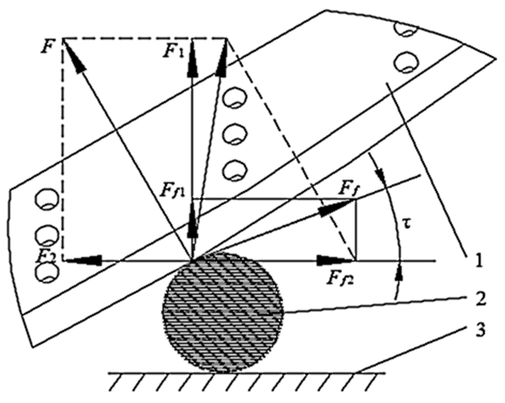
Using the chopper chopping a single ramie stalk as an example, the force analysis of the chopper blade was conducted [21,22,23]. In the process of chopping ramie stalk, the chopper receives the normal reaction force F and tangential friction force Ff of ramie stalk to the blade edge line. The feeding thrust T along the axial direction of ramie stalk can be neglected at the contact point (force bearing point) between its blade and ramie stalk. The stress analysis and calculation diagram are illustrated in Figure 2.
From Figure 2:
F 0 = F 1 + F f 1 = F cos τ + F f sin τ
In the formula, F is the normal reaction force on a force bearing point on the blade edge line of the chopper, N; Ff is the tangential friction force on the same force bearing point on the blade edge line of the chopper, N; τ is the sliding chopping angle of the same force bearing point on the blade edge line of the chopper, (°); f is the friction coefficient between the blade edge line of the chopper and the ramie stalk; and Ff = f × F.
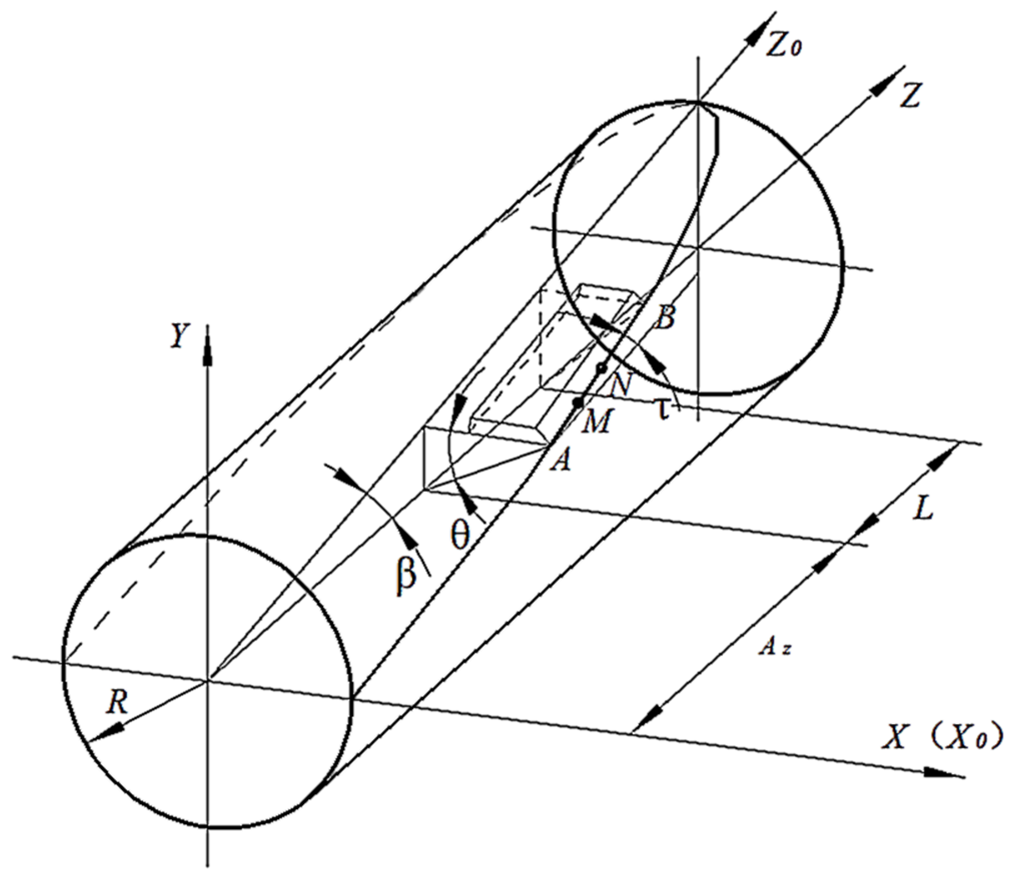
The structural parameters of the flat blade on the chopper are illustrated in Figure 3. The blade edge line of the chopper is part of the elliptic curve in the X0Z0 plane coordinate system. The X0Z0 plane coincides with the bottom surface of the blade to ensure that the gap between moving knife and stationary knife is always a certain value.
As shown in Figure 3, the relationship between the structural parameters of blade of the chopper is as follows:
A Z tan β = R sin θ A
In the formula, Az is the coordinate value of point A on the blade edge line on the Z axis, m; β is the inclination angle, which is the included angle between the bottom surface of blade of the chopper and the axis of cutter roll of the chopper, β∈(4°,7°) [24]; R is radius of the chopper, m; and θA is the installation rake angle of point A on the blade edge line of the chopper, (°).
Using two points M(Mx, My, Mz) and N(Nx, Ny, Nz) on the blade edge line AB of the chopper, record Mz = Az + t, Nz = Mz + Δt. Then, the slope of secant MN can be obtained from the geometric relationship as follows:
tan τ M N = | N x M x | | N z 0 M z 0 | = | R 2 ( A Z + t + Δ t ) 2 tan 2 β R 2 ( A Z + t ) 2 tan 2 β | × cos β Δ t
In the formula, t is the coordinate value difference of two points M and A on the blade edge line of the chopper on the Z axis, t ∈ (0, 0.29 m) [20]; and Δt is the coordinate value difference of two points M and N on the blade edge line of the chopper on the Z axis, m.
As shown in Figure 3, when point N approaches point M infinitely along the blade edge line AB and when Δt→0, the limit of Formula (4) exists. Then, this limit can be considered as the tangent slope of the blade edge line at point M:
l i m Δ t 0 tan τ M N = ( A Z + t ) × tan 2 β × cos β R 2 ( A Z + t ) 2 tan 2 β
And because points M and N are arbitrariness, then Formula (5) is the tangent slope of any point on the blade edge line. Change Formula (5) and combine Formulas (1) and (2) to obtain:
P = [ F cos ( arctan ( A Z + t ) × tan 2 β × cos β R 2 ( A Z + t ) 2 tan 2 β ) + f F sin ( arctan ( A Z + t ) × tan 2 β × cos β R 2 ( A Z + t ) 2 tan 2 β ) ] × R × ω
As shown in Formula (6), the power of the chopper is related to the coordinate value Az of point A on the blade edge line in the Z axis, the included angle β between the bottom surface of the blade and the axis of the cutter roll axis, and the radius R of the chopper. Therefore, an optimization model with Az, β, and R as the design variable can be established. The design variable is [25]:
X = ( x 1 x 2 x 3 ) T = ( A Z β R ) T
Using t = 0.15 m and substituting F = 179 N [26], f = 0.33 [27], and ω = 89 rad·s−1 [20] into Formula (6), the objective function can be determined as:
f ( X ) = f ( x 1 , x 2 , x 3 ) = [ 179 cos ( arctan ( x 1 + 0.15 ) × tan 2 x 2 × cos x 2 x 3 2 ( x 1 + 0.15 ) 2 tan 2 x 2 ) + 59 sin ( arctan ( x 1 + 0.15 ) × tan 2 x 2 × cos x 2 x 3 2 ( x 1 + 0.15 ) 2 tan 2 x 2 ) ] × 89 x 3

2.2. Constraint Condition

2.2.1. Continuity of Chopping Motion

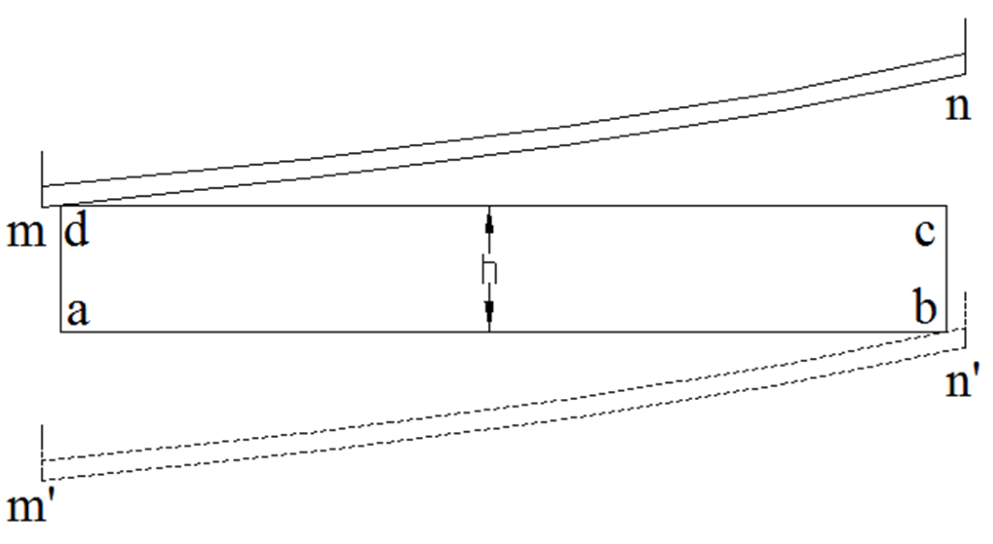
The chopping motion continuity refers to the chopper blade edges chopping at all times in a rotation cycle. As shown in Figure 4, abcd denotes the simplified ramie stalk layer combination, ab represents the blade edge of stationary knife, and mn and m′n′ both denote the blade edge of the moving knife. When the left side of the moving knife contacts point d, the ramie stalk layer is compressed and the chopping starts. When the right side of the moving knife contacts point b, the chopping ends. To ensure the load is maintained continuously during the operation of the chopper, the layout of the blade of the chopper complies with the following requirements:
arcsin h R + ( θ B θ A ) = 360 ° i
In the formula, h is the thickness of ramie stalk layer, 31.5 mm [20]; i is the number of blades on the chopper, 8; θA is the installation rake angle of point A on the blade edge line of the chopper, (°); and θB is the installation rake angle of point B on the blade edge line of the chopper, (°).
After analyzing the geometric relationship in Figure 3, the expression of θA and θB can be determined. The following result may be achieved by substituted θA and θB into Formula (9):
g 1 ( X ) = arcsin 31.5 x 3 + ( arcsin ( x 1 + 0.29 ) × tan x 2 x 3 arcsin x 1 × tan x 2 x 3 ) 45 ° = 0

2.2.2. Stability of Chopping Motion

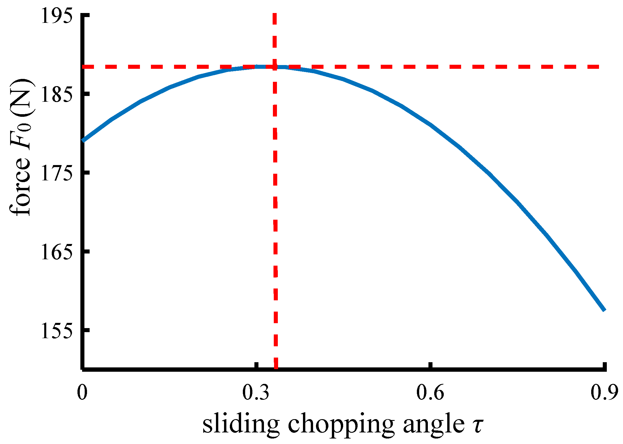
The relationship curve between the force F0 and the sliding chopping angle τ illustrated in Formula (2) is shown in Figure 5.
It is clear from Figure 5 that the force F0 increases initially and subsequently declines with an increase in sliding chopping angle τ. The value of the sliding chopping angle τ is closer to the extreme point (τ = 0.32 rad). The smaller the increase and decrease in the force F0 between the adjacent points on the blade edge line, the greater stability when the chopper works.
Sliding chopping is when the angle τ > 0 is no more than the friction angle of the blade edge line to the ramie stalk. Therefore, to guarantee that the chopper is constantly in the sliding chopping state throughout the working process, it should be τmax ≤ arctan f.
Additionally, along the positive direction of Z0 axis, the sliding chopping angle τ of each point on the blade edge line of the chopper gradually increases, resulting in the sliding chopping angle at point B on the blade edge line, which is τB = 0.32 rad, as shown in Figure 3. Namely:
g 2 ( X ) = ( x 1 + 0.29 ) × tan 2 x 2 × cos x 2 x 3 2 ( x 1 + 0.29 ) 2 tan 2 x 2 0.32 = 0
To summarize, the mathematical model for the optimal design of the structural parameters of the chopper is [28,29,30,31,32]:
f ( X ) = [ 179 cos ( arctan ( x 1 + 0.15 ) × tan 2 x 2 × cos x 2 x 3 2 ( x 1 + 0.15 ) 2 tan 2 x 2 ) + 59 sin ( arctan ( x 1 + 0.15 ) × tan 2 x 2 × cos x 2 x 3 2 ( x 1 + 0.15 ) 2 tan 2 x 2 ) ] × 89 x 3 g 1 ( X ) = arcsin 31.5 x 3 + arcsin ( x 1 + 0.29 ) × tan x 2 x 3 arcsin x 1 × tan x 2 x 3 45 ° = 0 g 2 ( X ) = ( x 1 + 0.29 ) × tan 2 x 2 × cos x 2 x 3 2 ( x 1 + 0.29 ) 2 tan 2 x 2 0.32 = 0 g 3 ( X ) = 4 ° x 2 0 g 4 ( X ) = x 2 7 ° 0

3. Using MATLAB to Optimize Calculation

Using MATLAB optimization toolbox, linear, nonlinear, and multiobjective programming problems can be solved [33]. The problems involved in this paper are constrained nonlinear problems, which can be solved by MATLAB program. Figure 6 depicts the process flow diagram for the calculations.
The specific program language is as follows:
(1) Write the M-file (fun_9_6.m) of the objective function:
function y = fun_9_6(x)
y = (50*cos(atan((x(1) + 0.15)*(tan(x(2)/180*pi))^2*cos(x(2))/sqrt(x(3)^2-((x(1) + 0.15)*tan(x(2)/180*pi))^2))) + 16.5*sin(atan((x(1) + 0.15)*(tan(x(2)/180*pi))^2*cos(x(2))/sqrt(x(3)^2-((x(1) + 0.15)*tan(x(2)/180*pi))^2))))*28*3.14*x(3);
end
(2) Since there are nonlinear constraints in the constraints, the M-file (fun_9_6_1.m) describing the nonlinear constraints is prepared:
function [f,g] = fun_9_6_1(x)
f = [];
g = [(x(1) + 0.29)*(tan(x(2)/180*pi))^2*cos(x(2))/sqrt(x(3)^2-(x(1) + 0.29)^2*(tan(x(2)/180*pi))^2)-0.32;
asin(0.0315/x(3))*180/pi + asin((x(1) + 0.29)*tan(x(2)/180*pi)/x(3))*180/pi-asin(x(1)*tan(x(2)/180*pi)/x(3))*180/pi-45];
end
(3) After the initial value is estimated according to the constraint conditions, the M-file (zxz_9_6.m) for solving the optimization mathematical model is compiled:
clear
clc
lb = [-inf 4 0.0315];
ub = [inf 7 inf];
[x value] = fmincon(‘fun_9_6’,[1 5 1],[],[],[],[],lb,ub,‘fun_9_6_1’);
(4) Run the M-file (zxz_9_6.m) to obtain:
X = [0.7 6 0.11]
Value = 1869.66
That is, the optimal values of the mathematical model for the optimal design of the structural parameters of the chopper are the coordinate value of point A on the blade edge line in the Z axis is 0.7 m, the included angle between the blade bottom and the cutter roll axis is 6°, and the radius of the chopper is 0.11 m.

4. Validation of Optimization Results

4.1. Verification by Software Analysis

The chopping power of the choppers before and after structural parameter optimization is analyzed by MATLAB software. Table 1 shows the structural parameters of the choppers before and after optimization.
As Table 1 shows, the following is the mathematical equation for the chopping power of each point on the chopper’s blade edge line:
P = [ 179 cos ( arctan ( A Z + t ) × tan 2 β × cos β R 2 ( A Z + t ) 2 tan 2 β ) + 59 sin ( arctan ( A Z + t ) × tan 2 β × cos β R 2 ( A Z + t ) 2 tan 2 β ) ] × 89 R
Substitute the structural parameters of the choppers before and after optimization in Table 1 into Formula (12). Draw the chopping power variation curve of each point on the blade edge line of the chopper with MATLAB software, as shown in Figure 7. The data statistical results corresponding to Figure 7 are shown in Table 2.
According to Formula (1), the power P is in positive proportion to the force F0, so the change trend of power can also represent the change trend of force. As shown in Figure 7, the variation curve of chopper chopping power before structural parameter optimization is approximately a horizontal straight line when t is less than 0.2 m and an evident curve when t is greater than 0.2 m. However, the variation curve of chopper chopping power after structural parameter optimization is approximately a horizontal straight line in the whole t range, indicating that the chopper after structural parameter optimization has more uniform force, less impact vibration, and more stable chopping movement.
In Table 2, the chopping power of the chopper after structural parameter optimization is roughly reduced 25.50% compared with that before optimization, indicating that the optimization effect is significant.

4.2. Verification by Bench Test

The bench test was conducted in the agricultural mechanization engineering training center of Hunan Agricultural University on 3 November 2020. In this case, Zhongzhu No. 1 is used as the test materials. About 60 days after the previous stubble was cut, the average height of ramie stalk was 899.47 mm, the average bottom diameter of the ramie stalk was 9.14 mm, and the moisture content was 71.56%.

4.2.1. Test Materials and Equipment

Test materials: The whole ramie stalk plant with uniform appearance and size was cut from the field for the test. Every 30 plants are a group, which is about the number of ramie stalk plants within 1 square meter of the field. A total of 10 groups of samples were prepared.
Test equipment: Performance test bench of the chopping system of the forage ramie harvester, a chopper before and after structural parameter optimization, one camera, a PTT-A2000 electronic balance of Fuzhou Huazhi Scientific Instrument limited company, and a ruler (1~200 mm) were used.
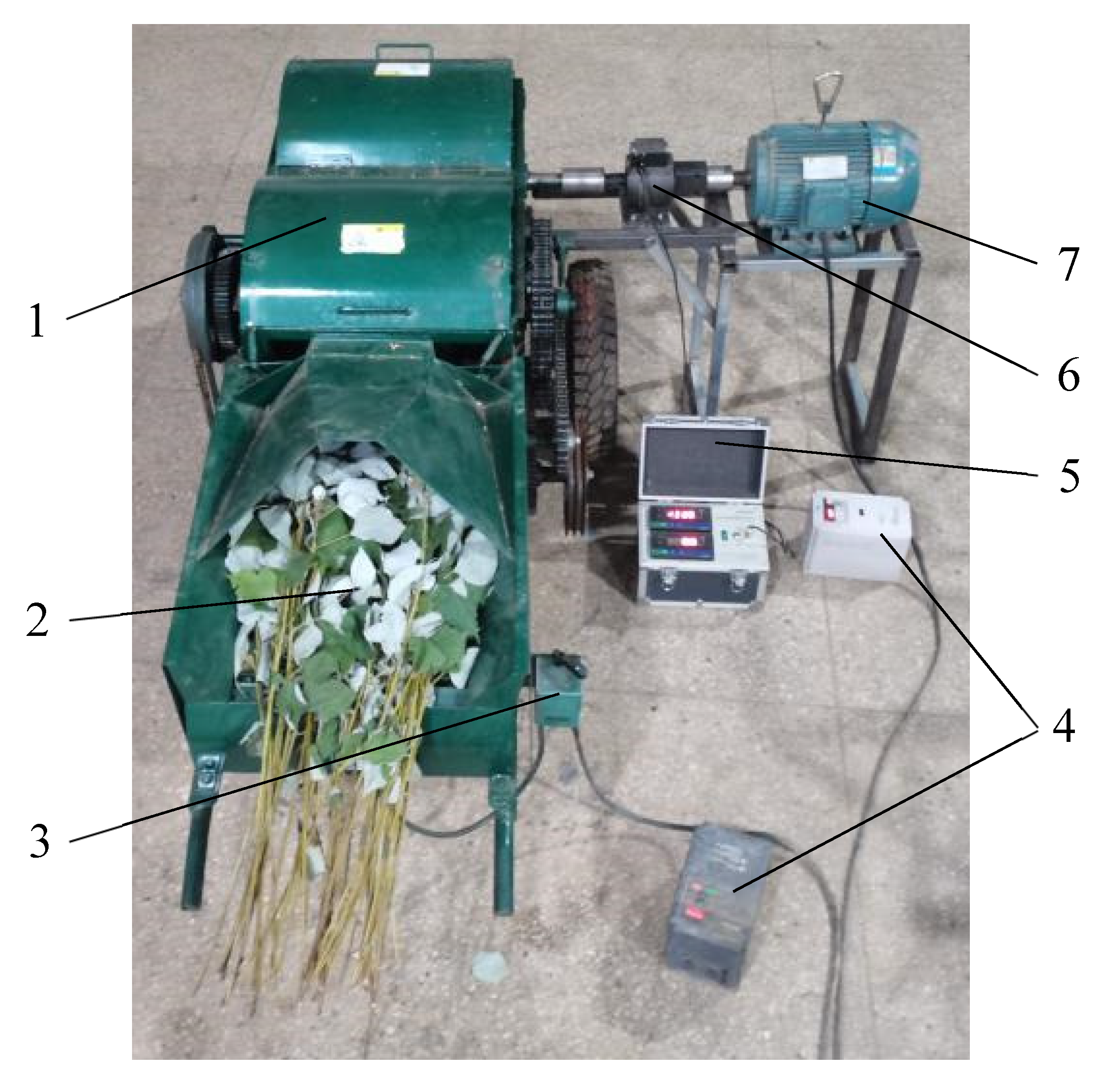
As shown in Figure 8, performance test bench of the chopping system of the forage ramie harvester includes one chopping system, two motors, two H710 frequency converters of Xuzhou haishang Frequency Conversion Technology limited company, one agricultural machinery torque and speed tester of Harbin Bona Technology limited company, and one CYB-803S torque sensor of Beijing West AVIC Technology limited company (0~1000 N·m). Among them, the chopper on the chopping system can be replaced, the gap between moving knife and stationary knife is set to 0.65 mm, and the rotate speed of feeding press roll and chopper can be adjusted by two frequency converters.

4.2.2. Test Method

After installing the chopper before the optimization of structural parameters on the chopping system of the forage ramie harvester, start two motors, respectively. Adjust the rotate speed of feeding press roll and chopper to 159 r·min−1 and 848 r·min−1 [20], respectively, through two frequency converters. After the chopping system of the forage ramie harvester runs smoothly, use the camera to record the continuous change situation of chopper torque value under no-load condition from the agricultural machinery torque and speed tester; the recording time is 20 s. Read the torque change value within 20 s from the recorded video, and record the average value as the torque value under no-load condition of the chopper.
Using a group of samples, lay them uniformly and orderly on the feeding conveyor belt for the test. Similarly, use the camera to record the continuous change situation of chopper torque value during the test. Read the torque change value during the test from the recorded video, and record the average value of the torque value under load condition of this testing group.
Finally, the chopping torque value of this testing group is determined by subtracting the torque value under no-load condition from the torque value under load condition of each group.
After a group of tests, turn off all motors. Use at least 100 g of small samples (except leaves) randomly from the chopped materials, measure the length of each section with a ruler, and then weigh the nonstandard length grass (unqualified) with a balance.
The test is repeated for five groups. After each group of tests, the chopping system of the forage ramie harvester is shut down and inspected to eliminate the interference of ramie stalk winding chopper and other influencing factors on the test results. After the completion of the first five groups of tests, the chopper before structural parameter optimization is replaced with the chopper after structural parameter optimization. The last five groups of tests are conducted according to the abovementioned test methods and the data recorded.

4.2.3. Test Index

The standard grass length rate and chopping power were selected as the test indexes. The calculation formulas of the two test indexes, respectively, are:
y = m b m z × 100 %
In the formula, y is the standard grass length rate, %; mb is the weight of standard-length grass, g; the standard-length grass refers to the length of chopped grass within the range of 0.7~1.2 times of the design chopping length [24]; and mz is the weight of the sample, g.
P = T × n 9550
In the formula: P is the chopping power, kW; T is the chopping torque, N·m; and n is the rotate speed of chopper, r·min−1.

4.2.4. Test Results and Analysis

Table 3 and Table 4 contains the test data and analytical findings for the two test indexes collected during the bench test.
Analyzing the data in Table 3, it can be found that:
(1)
The standard grass length rate (average value) of chopped ramie stalk by the chopper before and after the optimization of structural parameters is 92.96% and 92.84%, respectively, which are very close, indicating that the optimization of structural parameters basically has no influence on the chopping effect of the chopper.
(2)
After optimizing the structural parameters, the chopping power of the chopper is reduced by 22.25% compared with that before optimization, indicating the chopping power of bench test decreased significantly.
(3)
The standard deviation of the two test indexes of the chopper after structural parameter optimization is less than that before optimization, indicating that the working performance of the chopper after structural parameter optimization is more stable.

5. Discussion

(1)
The existing research on the power consumption of the chopper basically focuses on the working parameters of the chopper, the curve and shape of the chopper blade, and the installation parameters of the chopper on the machines and tools. However, this paper creatively considers the chopping power consumption of the chopper from the perspective of the structural parameters of the chopper (the installation form of the chopper blade on the knife roll), breaks the solidification thinking of the existing research, and provides a new idea and method to reduce the power consumption of the chopper.
(2)
The reason why the chopping power reduction in the bench test (22.25%) is lower than the software analysis value (25.50%) may be that other parts of the machine cause power loss, but the overall chopping power reduction in the bench test is obvious, which is basically close to the software analysis value, indicating that the optimization result is accurate and reliable.

6. Conclusions

(1)
When the coordinate value of point A on the blade edge line in the Z axis is 0.7 m, the included angle between the blade bottom and the cutter roll axis is 6°. When the radius of the chopper is 0.11 m, the chopper can obtain the theoretical minimum chopping power.
(2)
The software analysis results show that the chopper after the structural parameter optimization has more uniform stress, less impact vibration, and more stable chopping movement. The chopping power of the chopper after the optimization of structural parameters is approximately 25.50% lower than before the optimization, and the optimization effect is remarkable.
(3)
The bench test results show that the standard grass length rates of chopped ramie stalk by the chopper before and after the optimization of structural parameters were extremely close to each other. This demonstrates that the optimization of structural parameters basically has no influence on the chopping effect and quality of the chopper. After the optimization of structural parameters, the chopping power of the chopper is reduced by 22.25% compared with that before the optimization, which is close to the software analysis value, indicating that the optimization result is accurate and reliable. The standard deviation of the two test indexes of the chopper after structural parameter optimization is less than before optimization, indicating that the working performance of the chopper following structural parameter optimization is more stable.

Author Contributions

Conceptualization, A.Y., M.W. and J.L.; methodology, A.Y. and M.W.; software, A.Y.; validation, W.X. and B.Y.; formal analysis, A.Y., W.X. and B.Y.; investigation, A.Y. and Y.D.; resources, A.Y. and Y.D.; data curation, Y.D.; writing—original draft preparation, A.Y.; writing—review and editing, A.Y. and M.W.; visualization, A.Y.; supervision, J.L.; project administration, A.Y., M.W. and J.L.; funding acquisition, A.Y. All authors have read and agreed to the published version of the manuscript.

Funding

This research was funded by National hemp industry technology system primary processing mechanization post project, grant number “CARS-16-E21”; Key projects of Hunan Provincial Department of science and technology, grant number “2019NK2151”; General project of Hunan Provincial Department of Education, grant number “21C0129”; “Double first-class” construction project of Hunan Agricultural University, grant number “SYL201802018”.

Institutional Review Board Statement

Not applicable.

Informed Consent Statement

Not applicable.

Data Availability Statement

All data are presented in this article in the form of figures and tables.

Conflicts of Interest

The authors declare no conflict of interest.

References

  1. Che, G.; Wan, L.; Zhang, W. Solid design and experiment of forage harvester. Trans. Chin. Soc. Agric. Mach. 2010, 41, 82–86. [Google Scholar]
  2. Zhang, Y.; Diao, P.; Du, R. Design and test of stalk chopping and conveying device for corn combine reaping both stalk and spike. Trans. Chin. Soc. Agric. Mach. 2016, 47, 208–214. [Google Scholar]
  3. Jiang, Y.; Liao, Y.; Liao, Q. Design and experiment on cylinder-type chopping device of harvester for fodder rapeseed in winter and spring. Trans. Chin. Soc. Agric. Mach. 2019, 50, 102–111. [Google Scholar]
  4. Wan, Q.; Wang, D.; Wang, G. Design and experiment of self-propelled grass silage combined bagging machine. Trans. Chin. Soc. Agric. Eng. 2014, 30, 30–37. [Google Scholar]
  5. Li, B.; Wang, S.; Yang, B. Force analysis of two kinds of moving blades on chopper. Trans. Chin. Soc. Agric. Mach. 2005, 36, 49–52. [Google Scholar]
  6. Lin, G.; Ji, J.; Mao, J. Research and analysis of power consumption on flywheel-type cutterhead for dry forage. Trans. Chin. Soc. Agric. Mach. 1997, 28, 70–74. [Google Scholar]
  7. Guo, Y. Effect of fly-wheel cutterhead with different curve edges on cutting energy consumption. J. Jilin Agric. Univ. 2003, 25, 107–110. [Google Scholar]
  8. Deng, C.; Chen, F.; Deng, C. Design of small straw chopper. J. Agric. Mech. Res. 2011, 33, 141–143. [Google Scholar]
  9. Tian, K.; Li, X.; Zhang, B. Design and Test Research on Cutting Blade of Corn Harvester Based on Bionic Principle. Appl. Bionics Biomech. 2017, 2017, 6953786. [Google Scholar] [CrossRef] [Green Version]
  10. Jin, T.; Shun, X.; Chen, D. Design of a Bionic Blade for Vegetable Chopper. J. Bionic Eng. 2017, 14, 163–171. [Google Scholar]
  11. Jia, H.; Wang, Z.; Ma, C. Chopping and throwing mechanism of corn straw. Trans. Chin. Soc. Agric. Mach. 2003, 34, 96–99. [Google Scholar]
  12. Jia, H.; Ma, C. Study on chopping and throwing parameters of the chopping knife with curved surface and straight edge. Trans. Chin. Soc. Agric. Mach. 2002, 33, 41–43. [Google Scholar]
  13. Jamshidpouya, M.; Najafi, G.; Hashjin, T.T. Design fabrication and evaluation of electric forage chopper with adjustable helix angle. J. Agric. Sci. Technol. 2018, 20, 923–938. [Google Scholar]
  14. Hu, J.; Ma, S.; Wang, F. Design and Development of Sugarcane Top Chopper and its Field Performance. Sugar Tech 2021, 23, 1192–1198. [Google Scholar] [CrossRef]
  15. Xue, Z.; Fu, J.; Chen, Z. Optimization experiment on parameters of chopping device of forage maize harvester. J. Jilin Univ. Eng. Technol. Ed. 2020, 50, 739–748. [Google Scholar]
  16. Johnson, P.C.; Clementson, C.L.; Mathanker, S.K. Cutting energy characteristics of miscanthus x giganteus stems with varying oblique angle and cutting speed. Biosyst. Eng. 2012, 112, 42–48. [Google Scholar] [CrossRef]
  17. Fang, M.; Bie, Z.; Yu, Z. Experimental study on cutting performance of discutter chaff cutter. Trans. Chin. Soc. Agric. Mach. 2020, 41, 67–72. [Google Scholar]
  18. Ge, Y.; Jiang, Y.; Li, Y. Design and test for hob-type chopped roller of green fed harvester. IOP Conf. Ser. Mater. Sci. Eng. 2018, 382, 032061. [Google Scholar] [CrossRef]
  19. Thangdee, D.; Thangdee, S. The effect of blade type and speed to the bananas plant chopping machine. IOP Conf. Ser. Earth Environ. Sci. 2019, 301, 012012. [Google Scholar] [CrossRef]
  20. Yang, A.; Wu, M.; Lv, J. Design and experiment on chopping system of forage ramie harvester. J. Agric. Sci. Technol. Res. 2020, 22, 110–118. [Google Scholar]
  21. Liu, P.; He, J.; Li, Y. Design and experiment of double rollers maize stalk chopping device with different rotation speeds. Trans. Chin. Soc. Agric. Mach. 2020, 36, 69–79. [Google Scholar]
  22. Zhou, J. The Influence of the Relative Position between Paired Blades on the Cutting Quality of Billet Combine Harvester; South China Agricultural University: Guangzhou, China, 2017. [Google Scholar]
  23. Li, J. Cattail Chopped Structure Optimization Design; Yunnan Agricultural University: Kunming, China, 2016. [Google Scholar]
  24. Chinese Academy of Agricultural Mechanization Sciences. Agricultural Machinery Design Manual; China Agricultural Machinery Science and Technology Press: Beijing, China, 2007. [Google Scholar]
  25. Sun, J. Mechanical Optimization Design; China Machine Press: Beijing, China, 2003. [Google Scholar]
  26. Xu, X. The Design and Key Components Simulation of the New Ramie Decorticator; Chinese Academy of Forestry: Beijing, China, 2018. [Google Scholar]
  27. Li, B. Research on the One-Sheet Hyperboloid Cylindrical Cutter with Flat Surface and Straight Edge; China Agricultural University: Guangzhou, China, 2005. [Google Scholar]
  28. Yuan, X.; Teng, Z.; Tao, D. Optimal worm transmission design based on MATLAB. J. Hunan Agric. Univ. Nat. Sci. 2007, 33, 101–104. [Google Scholar]
  29. Zhou, M.; Zhang, L.; Chen, Y. Structural optimization for rack of boat-type tractor based on sensitivity analysis. Trans. Chin. Soc. Agric. Eng. 2016, 32, 54–60. [Google Scholar]
  30. Tao, D.; Sun, S.; Lu, Y. Optimization design of gear transmission box for tiller. Trans. Chin. Soc. Agric. Mach. 2001, 32, 118–120. [Google Scholar]
  31. Wu, M.; Guan, C.; Tang, C. Optimization of rotary-cultivated ditch mechanism of type 2BYF-6 no-till rape combine seeder. J. Hunan Agric. Univ. Nat. Sci. 2008, 34, 735–738. [Google Scholar]
  32. Deng, C.; Xiang, J.; Tao, D. Optimize on Working Parameters Crank Rolling Velocity and Radius of the Vibration Sieve about Cereal Cleaning Windmill. J. Hunan Agric. Univ. Nat. Sci. 2013, 29, 250–257. [Google Scholar]
  33. Su, J.; Ruan, S.; Wang, Y. Matlab Engineering Mathematics; Electronic Industry Press: Beijing, China, 2005. [Google Scholar]
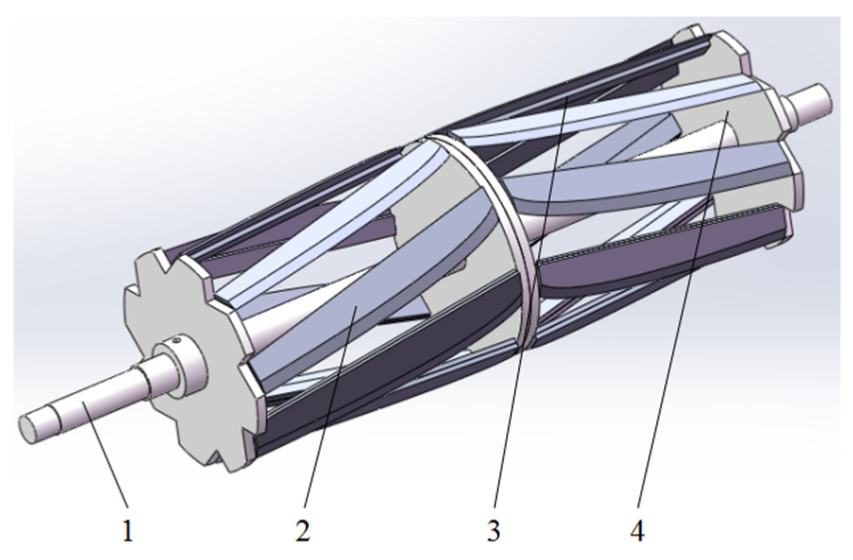
Figure 1. Flat hob chopper: 1. knife roller shaft; 2. blade; 3. knife holder; and 4. blade fixing plate.
Agriculture 12 00824 g001
Figure 2. Force analysis and calculation diagram of blade of the chopper: 1. blade of the chopper; 2. ramie stalk; and 3. fixed knife.
Agriculture 12 00824 g002
Figure 3. Structure parameters of blade on the chopper.
Agriculture 12 00824 g003
Figure 4. Schematic diagram of continuity analysis.
Agriculture 12 00824 g004
Figure 5. Relation curve between force F0 and sliding chopping angle τ.
Agriculture 12 00824 g005
Figure 6. Calculation flowchart for MATLAB.
Agriculture 12 00824 g006
Figure 7. Chopping power consumption of each point on the blade line.
Agriculture 12 00824 g007
Figure 8. Chopping system performance test bench: 1. chopping system; 2. ramie stalk; 3. motor switch of feeding part; 4. frequency converter; 5. agricultural machinery torque and speed tester; 6. torque sensor; and 7. control motor of chopper.
Agriculture 12 00824 g008
Table 1. Structure parameters of the choppers before and after optimization.
Az (m)Β (°)R (m)
Before optimization1.450.15
After optimization0.760.11
Table 2. Statistical results.
Power (W)
Minimum ValueMaximum ValueMean ValueMedianMode
Before optimization23862448240423982386
After optimization17761822179517931776
Decreased degree25.57%25.57%25.33%25.23%25.57%
Table 3. Experimental data and analysis of standard grass length rate.
Number of TestsWeight of the Sample
(g)
Weight of the Unqualified
(g)
Standard Grass Length Rate
(%)
Mean Value of Standard Grass Length Rate
(%)
Standard Deviation of Standard Grass Length Rate
Before optimization1136.3410.1492.5692.960.13
2142.1310.0792.91
3153.859.8393.61
4139.6710.2292.68
5144.6210.0993.02
After optimization1143.1710.6792.5592.840.08
2149.969.9693.36
3148.4110.5892.87
4145.5610.4292.84
5138.9410.2892.60
Table 4. Experimental data and analysis of chopping power.
Number of TestsChopping Torque
(N•m)
Mean Value of Chopping Torque
(N•m)
Standard Deviation of Chopping TorqueChopping Power
(KW)
Decreased Degree Chopping Power
(%)
Before optimization183.8885.038.517.5522.25
281.80
388.38
482.46
588.63
After optimization165.9166.114.335.87
268.91
367.83
464.83
563.08
Publisher’s Note: MDPI stays neutral with regard to jurisdictional claims in published maps and institutional affiliations.