Abstract
In order to solve the problem of the poor seed-cleaning performance of the inside-filling pneumatic cotton precision seed-metering device, a double-sided seed-cleaning mechanism combining a seed-cleaning scraper and seed-disturbing air nozzle was designed which can realize alternate seed cleaning on both sides of the suction hole’s end surface. By constructing a mechanical model of the seed-cleaning process, the influence law of the seed-cleaning mechanism on the critical adsorption performance of cotton seed was clarified, and the key structure and parameters of the seed-cleaning mechanism were decided by combining a theoretical analysis with operational requirements. So as to explore the seed-cleaning performance, some relevant bench tests were carried out, with E’kangmian-10 coated de-linted cotton seeds with a moisture content of 8.92% (wet basis) serving as the test objects; and single seed rate, excessive cleaning rate, and missing cleaning rate were taken for test indicators. First of all, a single-factor comparison test was employed with the shape of the seed-cleaning scraper as the impact factor to choose the optimal one. The results of the comparison test showed that, no matter what shape of seed-cleaning scraper was adopted for the seed-metering device, the missing cleaning rates under the corresponding optimal seed-cleaning effect were greater than 5%, and the sharp scraper gave a better seed-cleaning performance than the flat scraper. Next, combining the sharp seed-cleaning scraper with the seed-disturbing air nozzle to form combined seed-cleaning mechanism of the seed-metering device, the Box–Behnken Design test was executed to explore the influence law about seed-cleaning distance, seed-disturbing distance, and seed-disturbing pressure on the seed-cleaning performance. Then the parameter optimization module was applied to achieve the best combination of operating parameters for the test factors. The test results indicated that the test factors influencing test indicators were in the following order: seed-cleaning distance, seed-disturbing pressure, and seed-disturbing distance. The optimal combination of parameters was a seed-cleaning distance of 3.1 mm, seed-disturbing distance of 6.2 mm, and seed-disturbing pressure of 2165 Pa. Lastly, based on the optimal combination, a verification test of seed-cleaning performance was performed, and the corresponding evaluation indexes were a single seed rate of 98.03%, missing cleaning rate of 1.42%, and excessive cleaning rate of 0.55%. In comparison with the optimal seed-cleaning effects under the single-sided seed-cleaning scrapers of flat and sharp shape, respectively, the combined double-sided seed-cleaning mechanism reduced 3.90 and 3.61 percentage points in missing cleaning rate, reduced 2.02 and 1.17 percentage points in excessive cleaning rate, and increased 5.92 and 4.78 percentage points in single seed rate, thus indicating that the combined double-sided seed-cleaning mechanism can effectively enhance the inside-filling pneumatic precision seed-metering device seed-cleaning performance. This study provides a reference for the design and parameter optimization of the seed-cleaning mechanism of a precision seed-metering device.
1. Introduction
Cotton is the vital economic crop and strategic material in China [1]. Sowing is the primary link of cotton production. Mechanized precision direct seeding technology has the advantages of saving cost and improving quality, and it can effectively increase the efficiency of cotton planting [2]. The seed-metering device is the key part of cotton planter, and its operational performance has a direct impact on the quality of seeding. At present, the commonly used cotton precision seed-metering device is classified into mechanical and pneumatic types according to working principle. The mechanical seed-metering device has rigorous limitations on the overall size of seeds, has a low efficiency of seeding, and can easily to damage seeds [3,4,5,6,7,8]. The main working link of the pneumatic seed-metering device relies on the airflow to complete the process, thus making it more adaptable to seeds and less prone to damaging them, highly efficient at seeding, and suitable for high-speed operation, among which the air-suction seed-metering device is most widely utilized [9,10,11,12,13,14,15,16].
Seed-filling and seed-cleaning processes are two vital and contradictory links of the seed-metering device. To prevent the occurrence of the missing seeding phenomenon, normally the filling performance should be increased as much as possible during the seed-filling process, while to ensure precision seeding, the requirements for seed-cleaning performance are higher. Currently, for the purpose of improving the working performance of the seed-metering device, scholars in domestic and foreign countries have performed a lot of research, which mainly focuses on improving the seed-filling performance; however, there is relatively less research on the seed-cleaning mechanism [17,18,19,20,21,22]. Liu Yunqiang et al. designed a double-row seed-cleaning mechanism to reduce the reseeding rate of the air-suction cylinder seed-metering device for planting non-spherical seeds and optimized its relevant structural parameters by conducting airflow field simulation [23]. Qi Bing et al. developed a circumferential seed-cleaning mechanism applied to a cylinder seeder to reduce the reseeding rate of centralized pneumatic corn precision seeders under low-speed operation [24]. Ding Li et al. optimized and designed a single-sided seed-cleaning device by analyzing the motion mechanism of seed-cleaning process and establishing a parametric mathematical model of seed-cleaning mechanism to reduce the high reseeding rate of a vertical disc air-suction corn-seed-metering device [25]. Li Yuhuan et al. designed a double-sided seed-cleaning mechanism to enhance the cleaning effect of vertical disc corn precision seed-metering device, and the comparison test with single-sided seed-cleaning mechanism showed that the double-sided seed-cleaning mechanism gives a better seed-cleaning performance and can effectively improve the seed-metering device operation effect [26]. The above research indicates that the existing seed-cleaning mechanisms are mainly applicable to air-suction cylinder or vertical disc air-suction seed-metering device, and there are few studies on the seed-cleaning mechanisms for the inside-filling pneumatic seed-metering device.
The inside-filling pneumatic seed-metering device can be filled with seeds by means of the inside-filling and airflow adsorption (pressure) method, so its seed-filling performance is better, but there is a problem of poor seed-cleaning performance caused by excessive cleaning and missing cleaning in the process of seed cleaning. Therefore, in this study, taking the inside-filling pneumatic cotton precision seed-metering device as the research object, a mechanism research study of seed-cleaning process was carried out and a double-sided seed-cleaning mechanism combining a scraper with a seed-disturbing air nozzle was designed. Furthermore, a comparison and Box–Behnken Design tests were adopted successively to obtain the optimal seed-cleaning performance, with a view to improving the seed-cleaning effect of inside-filling pneumatic seed-metering device and providing a reference for the design and parameter optimization of the seed-cleaning mechanism for the precision seed-metering device.
2. Materials and Methods
2.1. Structure and Operating Principle of Seed-Metering Device
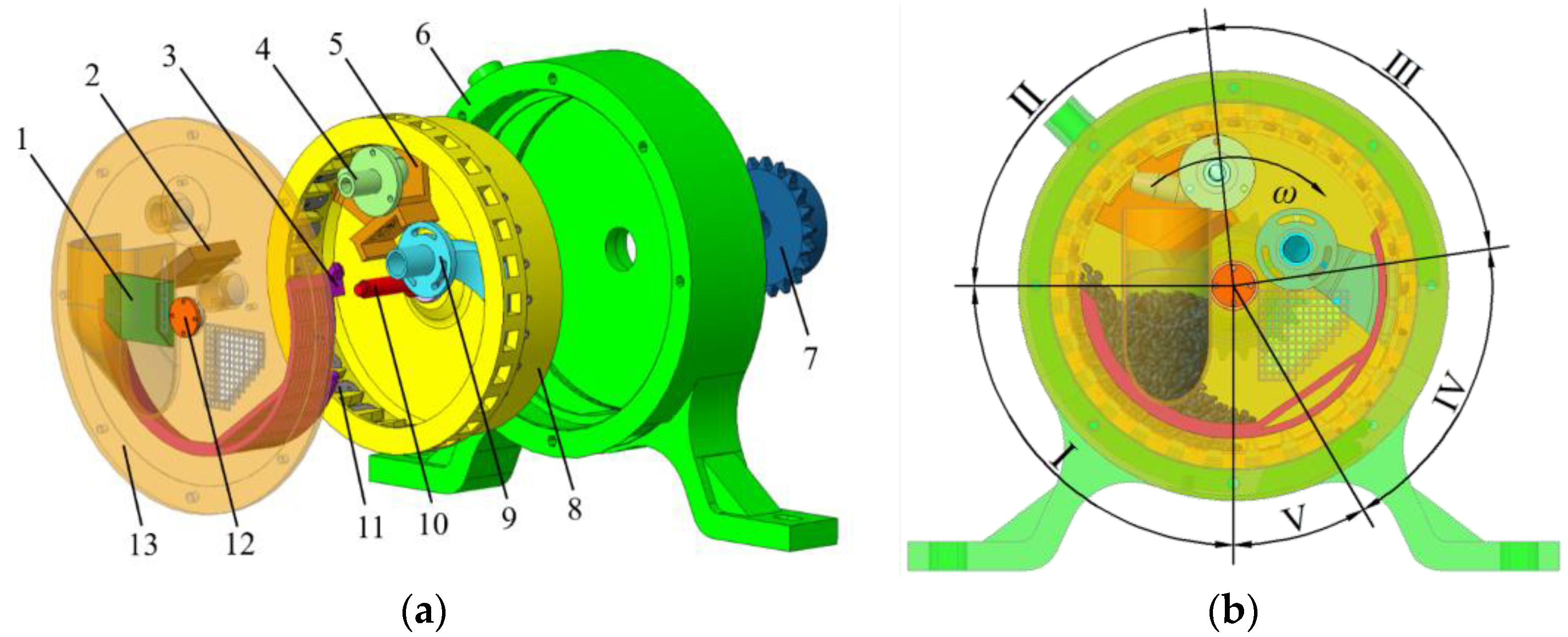
The structure of the inside-filling pneumatic cotton precision seed-metering device is shown in Figure 1a. The operating link of the seed-metering device consists of five parts: seed-filling zone, seed-cleaning zone, seed-carrying zone, primary seed-throwing zone, and secondary seed-throwing zone, as shown in Figure 1b. The seeding plate is driven to rotate clockwise by the seeding shaft, and the lower cotton seeds in the seed cluster are filled into the type hole. When the type hole is rotated to the seed-cleaning zone, the multiple cotton seeds around the suction hole are cleaned and fall back to the inner cavity by the joint action of the seed-cleaning scraper and seed-disturbing air nozzle. The remaining single cotton seed enters the primary seed-throwing zone after passing through the seed-carrying zone with the suction hole, and then blown into the collection hole from the suction hole by the action of high-speed airflow of the seed throwing air nozzle. After rotating a certain angle, the cotton seed reaches the secondary seed-throwing zone and is thrown out through the seed exit of the back shell to complete the seeding process.

Figure 1.
Structural schematic diagram of seed-metering device: (a) decomposition view and (b) schematic representation of operating process division. (1) Adjusting plate, (2) scraper foundation, (3) baffle, (4) seed-disturbing air nozzle, (5) seed-cleaning scraper, (6) back shell, (7) chain wheel, (8) seeding plate, (9) seed-throwing air nozzle, (10) seeding shaft, (11) replacement board, (12) end cap, (13) fore shell. (I) Seed-filling zone, (II) seed-cleaning zone, (III) seed-carrying zone, (IV) primary seed-throwing zone, and (V) secondary seed-throwing zone.
The seed-cleaning process is the core stage to realizing the precision seeding of the seed-metering device, and its operational performance is closely related to the sowing quality. Considering the structural characteristics and operating principle of the inside-filling pneumatic seed-metering device, a double-sided seed-cleaning mechanism combining a seed-cleaning scraper and seed-disturbing air nozzle was designed. The seed-cleaning scraper adopts the three-segment type, which is embedded and slides with the scraper foundation and can be move in the direction of seeding-plate axis. The seed-disturbing air nozzle adopts a double-outlet bifurcated air nozzle, whose outlets are located between adjacent segment scrapers, respectively. After the multiple seeds adsorbed at the suction hole are collided by the first segment scraper, the remaining small amount of cotton seeds is squeezed into the inner side of the type hole. When the seeds rotate with the suction hole to the first outlet of the seed-disturbing air nozzle, the unstable adsorbed seeds fall back to the inner cavity under the action of the airflow, and the rest of the seeds rotate to the outside of the type hole that facilitates the next segment scraper to clean the seeds. Furthermore, the cotton seeds at the suction hole are successively acted upon by the second segment scraper, the airflow from the air nozzle second outlet, and the third segment scraper alternately to achieve single-seed adsorption.
2.2. Re-Adsorption Phenomenon and Analysis of the Seed-Cleaning Process
2.2.1. Re-Adsorption Phenomenon
Seed-filling process is the primary link of the seed-metering device; in order to ensure a better filling effect, the seed-metering device adopts the form of inside-filling pneumatic type, which can be filled with seed by means of the inside-filling and airflow adsorption method [21]. The seeding plate (including the replacement board and fastening screws) is equipped with an annular groove and several evenly distributed type holes on its inner wall, as shown in Figure 2. The type hole consists of the filling hole and collection hole, and its sidewall has a disturbing effect on the seed cluster in the inner cavity, which can improve the mobility of cotton seeds. Moreover, the sidewall of the type hole has a certain supporting effect on the cotton seeds filled into the type hole during the seed-filling stage, which can prolong the filling time of the cotton seeds, thus further improving the seed-filling performance.
Figure 2.
Top view of seeding plate: (1) fastening screw, (2) suction-hole replacement plate (3) suction hole, (4) filling hole, (5) collection hole, (6) annular groove, and (7) type hole.
Since the cotton seed is a natural product, its shape size is irregular, and the suction hole’s structure is a straight cylindrical type, the seed cannot fit completely on the suction hole’s end surface during the seed-filling process, so there is airflow leakage. The cotton seeds near the suction hole gradually move to its end surface and adsorbed on it under the action of strong drag force, so it is easy to lead to the situation of multiple seeds’ adsorption at a single suction hole, that is, the re-adsorption phenomenon. In the previous test, it was found that, after the suction hole was separated from the seed cluster, there were usually 2–4 cotton seeds adsorbed on its end surface, so it indicated that the seed-filling effect of the seed-metering device is good, but to satisfy the goal of single seed precision seeding, the seed-cleaning performance was required to be higher.
2.2.2. Analysis of the Seed-Cleaning Process
Analysis of the Seed-Cleaning Scraper
The front end of the seed-cleaning scraper is placed in the annular groove to collide with and squeeze the multiple seeds adsorbed at the suction hole for scraping off the unstable seeds and pushing the remaining seeds to the inner side of the type hole, and then the seeds are blown to the outside of the type hole by the airflow from the seed-disturbing air nozzle, so that the seed-cleaning scraper can achieve intermittent collision for many times to realize the precise seeding. To further investigate the influence of seed-cleaning scraper on the adsorption stability of cotton seed, taking a single cotton seed acted by the seed-cleaning scraper as the research object, the mechanics model was established as shown in Figure 3. To simplify the analysis and calculation, the cotton seed is considered as a rigid ellipsoid [27], and the Cartesian coordinate system is established with its center of mass as the origin, O. The XOY plane passes through the center of mass of the cotton seed and is parallel to the suction hole’s end surface to which the cotton seed is adsorbed; the X-axis is parallel to the seeding plate’s axis, with the positive direction pointing to the type hole’s inner side; the Y-axis is vertical to the X-axis, with positive direction deviating from the rotation direction of the seeding plate; and the Z-axis coincides with the central line of the suction hole and points to the central axis of the seeding plate.

Figure 3.
Force analysis of the cotton seed in seed-cleaning process. Note: A, projection point of the critical rollover point on the XOY plane; O1, the intersection of Z-axis and central axis of seeding plate; Fp, adsorption force on cotton seed, N; Fl, centrifugal force, N; G, gravity, N; FN, support force on cotton seed by replacement plate, N; Ft, pushing force on cotton seed by scraper, N; Ftxy, projection from Ft in the XOY plane, N; Ftz, projection from Ft in the Z-axis, N; Ff, friction force on cotton seed by scraper, N; Ff1, friction force on cotton seed by replacement plate, N; α, angle of Fl with horizontal plane, (°); β, angle of Ft with XOY plane, (°); γ, angle of Ftxy with X-axis, (°); and ξ, angle of the straight line OA with X-axis, (°).
The projection point, A, of the critical rollover point, A0, of the cotton seed without rolling in the XOY plane is in the direction where the projected resultant force of gravity, centrifugal force, adsorption force, the pushing force, and friction force on cotton seed in this plane. Therefore, the angle of line OA with the X-axis, ξ, satisfies the following equation:
where Fx is resultant force along the direction of X-axis, N; and Fy is resultant force along the direction of Y-axis, N.
So as to guarantee that the cotton seed could be stably adsorbed on the suction hole’s end surface and avoid excessive cleaning, the adsorption force on the cotton seed needs to satisfy the critical condition of ΣMA0 = 0 in the triangular OAO1 plane [25]; the equation can be expressed as follows:
where d is diameter of suction hole, mm; l1 is projected length of the distance between the critical rollover point, A0, and the mass center of the cotton seed along the Z-axis, mm; l2 is the projected length of the distance between the critical rollover point, A0, and contact position of cotton seed and seed-cleaning scraper along the Z-axis, mm; m is the cotton seed weight, kg; R1 is distance between the cotton seed mass center and seeding plate axis, mm; ω is angular speed of seeding plate, rad·s−1; g is gravity acceleration, m·s−1; and μ is friction coefficient.
Because the seed-metering device is susceptible to re-adsorption during seed-filling process, when multiple seeds are adsorbed on the end surface of the suction hole, the area of the suction hole’s end surface that is occupied by each seed is different. Define the area of suction hole’s end surface occupied by the cotton seed i as Si, and the adsorption force on the cotton seed can be expressed as follows:
where ∆p is the pressure difference between the inner and outer sides of suction hole, N.
According to the Equations (1)–(3), the critical adsorption area of the cotton seed i can be obtained as follows:
The angle of line OA with the X-axis, ξ, is as follows:
It can be seen from the Equations (4) and (5) that the critical adsorption area, Si, is positively correlated with Ft, l1, l2, and m; negatively proportional to Δp; negatively correlated with d, β, R1, and ω; and related to the angle ξ. Meanwhile, the angle ξ is positively correlated with m and μ, negatively correlated with Ft and α, and related to β and γ. Therefore, there are many factors affecting the critical adsorption area of the cotton seed, but in general, they can be summarized into four categories: physical characteristics of the cotton seed (m, μ), performance parameters of seed-metering device (d, ω, Δp), adsorption position and attitude of the cotton seed (α, R1, l1), and interaction between the seed-cleaning scraper and the cotton seed (Ft, β, γ, l2). When the cotton seed species, seed-metering device structure, and working parameters are determined, the parameters of the first two categories are fixed, and because of the randomness of the cotton seed adsorption state, the discussion mainly focuses on the effect of the interaction between the seed-cleaning scraper and the cotton seed on the critical adsorption area. As the required adsorption area of the cotton seed increases with the pushing force of the seed-cleaning finger on the cotton seed, when multiple seeds are adsorbed on the end surface of the suction hole, increasing the pushing force tends to reduce the adsorption area of the seeds by squeezing them toward the inner side of the type hole, and this is conducive to the removal of the undominated seeds, so the design of the subsequent seed-cleaning scraper follows the approach of gradually increasing the pushing force to realize the goal of seed cleaning. Moreover, except for the magnitude of the pushing force, its vector direction (β, γ) also has a certain influence on the critical adsorption area and is related to the structural parameters of the seed-cleaning scraper; hence, based on the structural characteristics of inside-filling pneumatic seed-metering device, the structural parameters of seed-cleaning scraper will be further determined.
Analysis of the Seed-Disturbing Air Nozzle
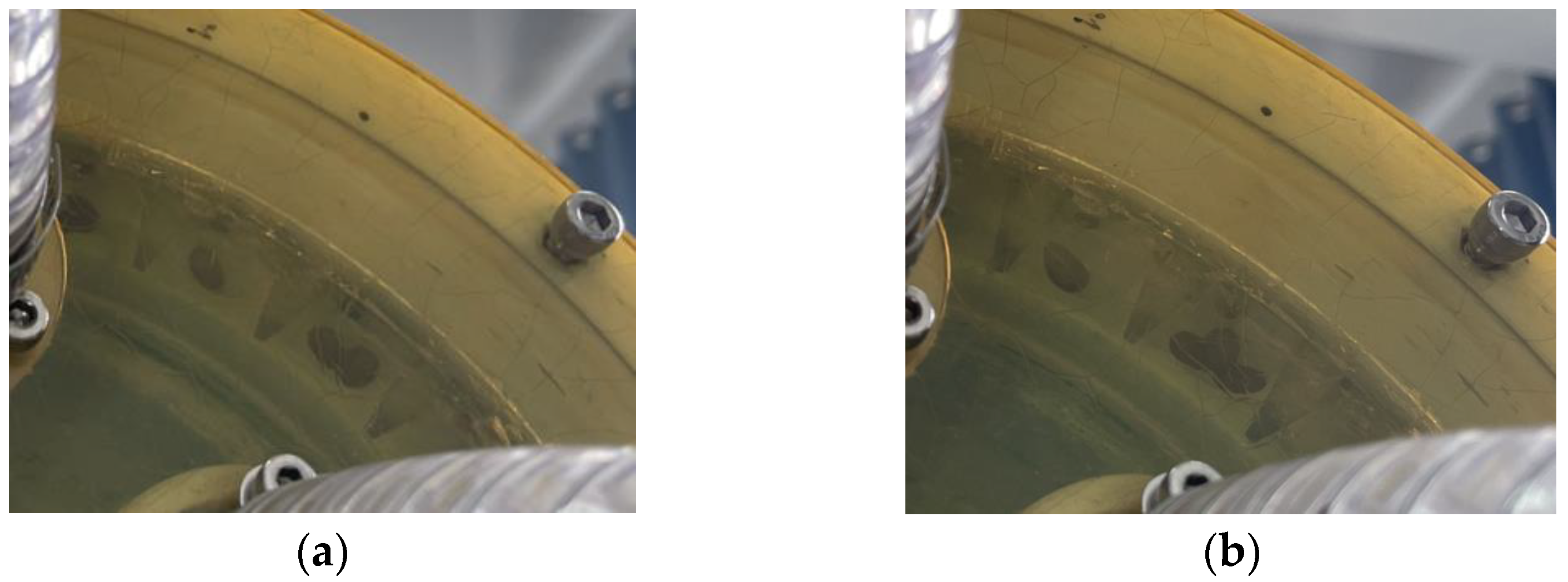
The front end of the seed-cleaning scraper is placed in the annular groove, and the plane where the central axes of the suction holes are located coincides with the front surface of the type holes. So as to ensure the normal operation of seed-metering device, the scraper can only touch the cotton seeds on the outside of the type hole. In the previous test, it was found that after the action of the seed-cleaning scraper, there were 2 or 3 cotton seeds (mainly 2 seeds) adsorbed on the end surface of the suction hole and the position biased toward the inner side of the type hole, as shown in Figure 4. Since the inner side of the type hole is surrounded by its sidewall, it is difficult to use a rigid device to contact the re-adsorbed cotton seeds inside it, so a non-contact airflow is considered for disturbance. The high-speed airflow from the seed-disturbing air nozzle can remove the unstable cotton seeds from the inner side of the type hole and blow the remaining seeds out of the type hole inner side for next segment scraper to clean the seeds. By means of the alternating action of the scraper and the seed-disturbing air nozzle, we can achieve the adsorption of a single cotton seed on the end surface of the suction hole.

Figure 4.
Adsorption of multiple cotton seeds after the separate action of the seed-cleaning scraper: (a) two cotton seeds and (b) three cotton seeds.
2.3. Design of the Seed-Cleaning Mechanism
2.3.1. Design of the Seed-Cleaning Scraper
The seed-cleaning scraper is the main component that can improve the seed-cleaning accuracy. Currently, the commonly used seed-cleaning mechanisms for pneumatic seed-metering device include serrated type, smooth curve type, lever type, brush type, etc. [6,28]. Considering the working principle and installation method of the seed-cleaning mechanism, the seed-cleaning scraper adopts three-segment serrated scraper.
Installation Position of the Seed-Cleaning Scraper
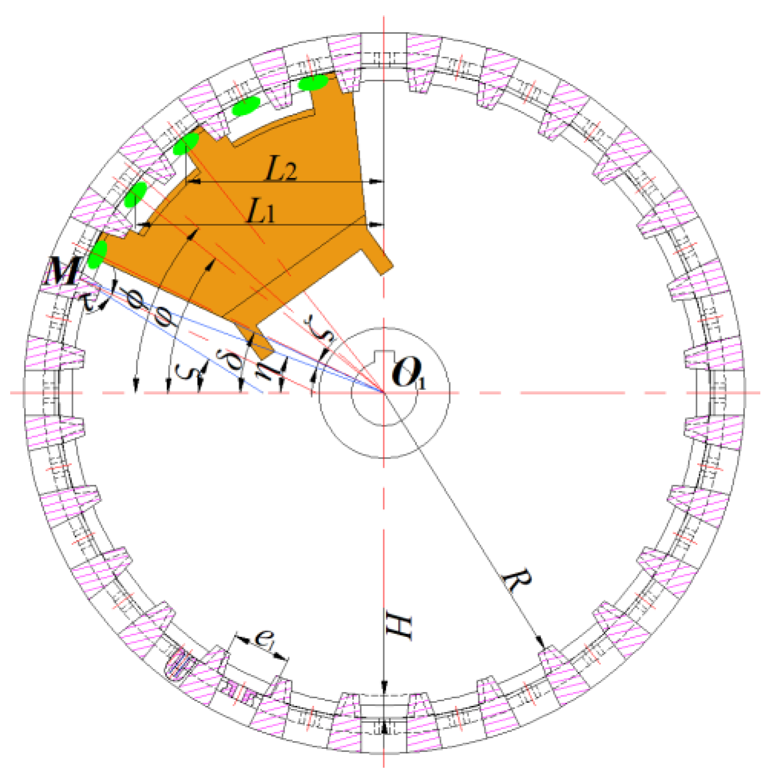
To ensure the smooth running of seed-cleaning process, the installation position of seed-cleaning scraper must meet the following two conditions: (1) Before the re-adsorbed cotton seeds are rotated into the seed-cleaning scraper area, it is necessary to make sure that cotton seeds in type hole can slide along its sidewall, so as to avoid that the cotton seeds cleaned by seed-cleaning scraper cannot slide down smoothly. (2) During the process of seed cleaning, the cotton seeds removed by seed-cleaning mechanism on the latter suction hole’s end surface do not interfere with the cotton seeds adsorbed on the former suction hole’s end surface. The schematic diagram of the installation position for the seed-cleaning scraper is as shown in Figure 5.

Figure 5.
Schematic diagram of seed-cleaning scraper installation position. Note: M, the lower vertex of the lower bottom edge of the front surface of the filling hole; L1, distance between mass center of cotton seed adsorbed on the suction hole’s end surface which is between the first and second segment scrapers and the vertical axis of the seeding plate, mm; L2, distance between mass center of cotton seed adsorbed on the suction hole’s end surface at the second segment scraper and the vertical axis of the seeding plate, mm; R, inner circle radius of seeding plate, mm; H, filling-hole height, mm; e1, width of lower bottom surface of the type hole at the plane where the suction holes axes are located, mm; δ, starting installation angle of seed-cleaning scraper, (°); η, angle of the straight line MO1 with horizontal axis of seeding plate, (°); ς, critical slip angle of the cotton seed at the plane where the suction holes axes are located, (°); τ, angle of the type hole sidewall with the axis of the corresponding suction hole at the plane where the suction holes axes are located, (°); ζ, angle of straight line MO1 with the corresponding suction hole axis, (°); ϕ, angle between the symmetrical centerline of the first and second segment scrapers and the horizontal axis of seeding plate, (°); and φ, angle of the suction hole axis which is between the first and second segment scrapers with the horizontal axis of the seeding plate, (°).
Since the filling hole is approximately an inverted trapezoid, its sidewalls are chamfered to 1.5 × 7 mm, so the sidewall inclination of the filling hole is minimum at the front surface. The front surface of the type holes coincides with the plane where the axes of the suction holes are located. In order to make sure that cotton seeds can slide along the type hole sidewall before the re-adsorbed cotton seeds enter into the seed-cleaning scraper zone, the starting installation angle of the seed-cleaning scraper, δ, should be greater than the central angle corresponding to the critical slip angle at the plane where the axes of the suction holes are located, η; the equation can be expressed as follows:
where ψ is sliding friction angle of cotton seed with seed-cleaning scraper.
The calculation formula of the angle between the straight line, MO1, and the axis of the corresponding suction hole is ζ = arctan(e1/2(R + H)). For the seed-metering device, the relevant structural parameters are e1 = 18 mm, R = 93 mm, and H = 7 mm. After calculation, the angle ζ = 5.14° is obtained. Moreover, the angle of the type hole’s sidewall with the corresponding suction hole axis at the plane where the suction holes axes are located is measured as τ = 6.27°.
The cotton seed variety E’kangmian-10 produced by Hubei Fuyue Seed Industry Technology Co., Ltd. (Hubei, China) was selected to be the test object. The surface of the cotton seed is smooth, the outline is nearly ovoid, and the center of gravity is close to the side of the large head. One hundred cotton seeds were randomly selected to measure the triaxial dimensions and the ratio of the distance between the width-thickness plane and the tip of the small head to the length of the cotton seed, J. After measurement, the length range of the cotton seeds was 7.94–11.01 mm, and the mean value was 9.27 ± 0.67 mm; the width range of the cotton seeds was 4.08–6.18 mm, and the mean value was 4.50 ± 0.33 mm; the thickness range of the cotton seeds was 3.74–5.29 mm, and the mean value was 4.50 ± 0.33 mm; and the range of the ratio J was 0.44–0.73 mm, and the mean value was 0.59 ± 0.06 mm.
The main parts for the precision seed-metering device were processed with a 3D printer (Wujiang Zhongrui Technology Co., Ltd., Wujiang, China, iSLA660 type, accuracy of 0.1 mm). The sliding friction angle of the main parts for the seed-metering device with cotton seed is ψ = (17.74 ± 2.86)°. Then, substituting τ = 6.27°, ζ = 5.14°, and ψ = 17.74° into Equation (6), the starting installation angle of the seed-cleaning scraper is obtained as δ > 6.33°.
The disturbing air nozzle acts on the type hole’s inner side, and the cotton seeds removed by the airflow will not interfere with the seeds adsorbed at the former suction hole due to the blocking of the type hole’s sidewalls. Moreover, in the seed-cleaning zone, as the seeding plate rotates clockwise, the projection distance between the centers of the two adjacent suction hole’s end surfaces on the horizontal plane gradually increases, meaning that the probability that the seeds removed at the latter suction hole interfere with the former suction hole is smaller. Therefore, in order to avoid that the cotton seeds removed by the seed-cleaning mechanism at the latter suction hole interfere with the cotton seeds adsorbed at the former suction hole during the seed-cleaning process, it is only necessary to ensure that the cotton seeds cleaned by the second segment scraper do not interfere with the cotton seeds adsorbed at the suction hole between the first and second segment scrapers. Assuming that the cotton seed is adsorbed on the end surface of the suction hole in a reclining position and its mass center coincides with the suction hole axis, the symmetrical centerline of the first and second segment scrapers should meet the following equation:
where K is the type hole number; and Lmax is the maximum length of cotton seeds, mm.
By substituting R = 93 mm, H = 7 mm, T = 4.50 mm, K = 28, and Lmax = 11.01 mm into Equation (7), the position of the symmetrical centerline of the first and second segment scrapers is obtained as ϕ > 23.57°. From the above analysis, it can be seen that the starting installation angle of the seed-cleaning scraper is δ > 6.33°. Moreover, with the increase of the starting installation angle, the more fully the re-adsorbed cotton seeds at the suction holes before entering the seed-cleaning zone are cleaned by gravity, and this is conducive to reducing the burden of the seed-cleaning device and the impact of removed cotton seeds upon the seed-cleaning performance; thus, the scraper starting installation angle was selected as δ = 25°. At this time, the angle between the symmetrical centerline of the first and second segment scrapers and the horizontal axis of the seeding plate was ϕ = 41.64°, and the operating range of the seed-cleaning scraper is [25°, 32.57°] ∪ [50.71°, 58.29°] ∪ [76.43°, 84°].
Determination of Key Parameters for the Seed-Cleaning Scraper
- (1)
- Front Part Width (a) and Top Radius (Rd)
The seed-cleaning scraper and the baffle are fixed in the fore shell; in order to avoid space position interference during the installation process, the front part of each segment of the seed-cleaning scraper should be able to reach into the groove of the type hole, so its width should be less than the width of the type hole. Since the width of the type hole varies from [14,18] mm, and the increase of the front part width of the seed-cleaning scraper is beneficial to improve its strength, the front part width was selected as a = 13 mm.
In order to avoid friction at the top of the scraper and the inner wall of the annular groove of the seed-metering device due to processing and installation errors, a gap of ∆ = 0.3 mm was set between them; that is, the radius of the top of the seed-cleaning scraper is Rd = R + H − ∆ = 99.7 mm.
- (2)
- Seed-Cleaning Part’s Thickness (b) and Seed-Cleaning Part’s Extended Length (c)
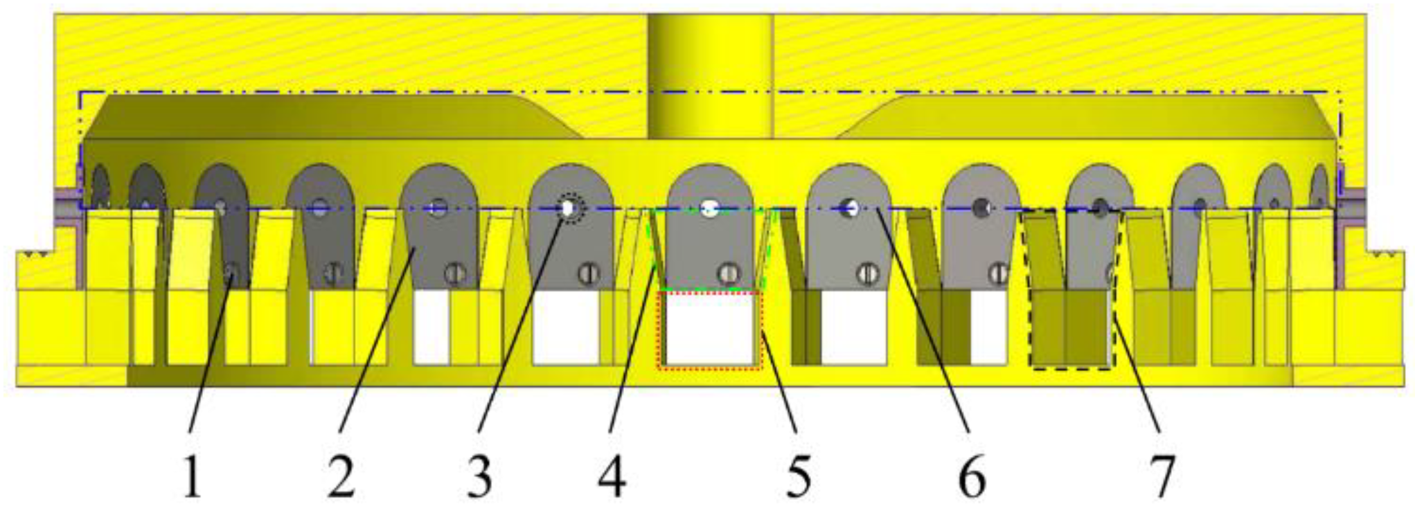
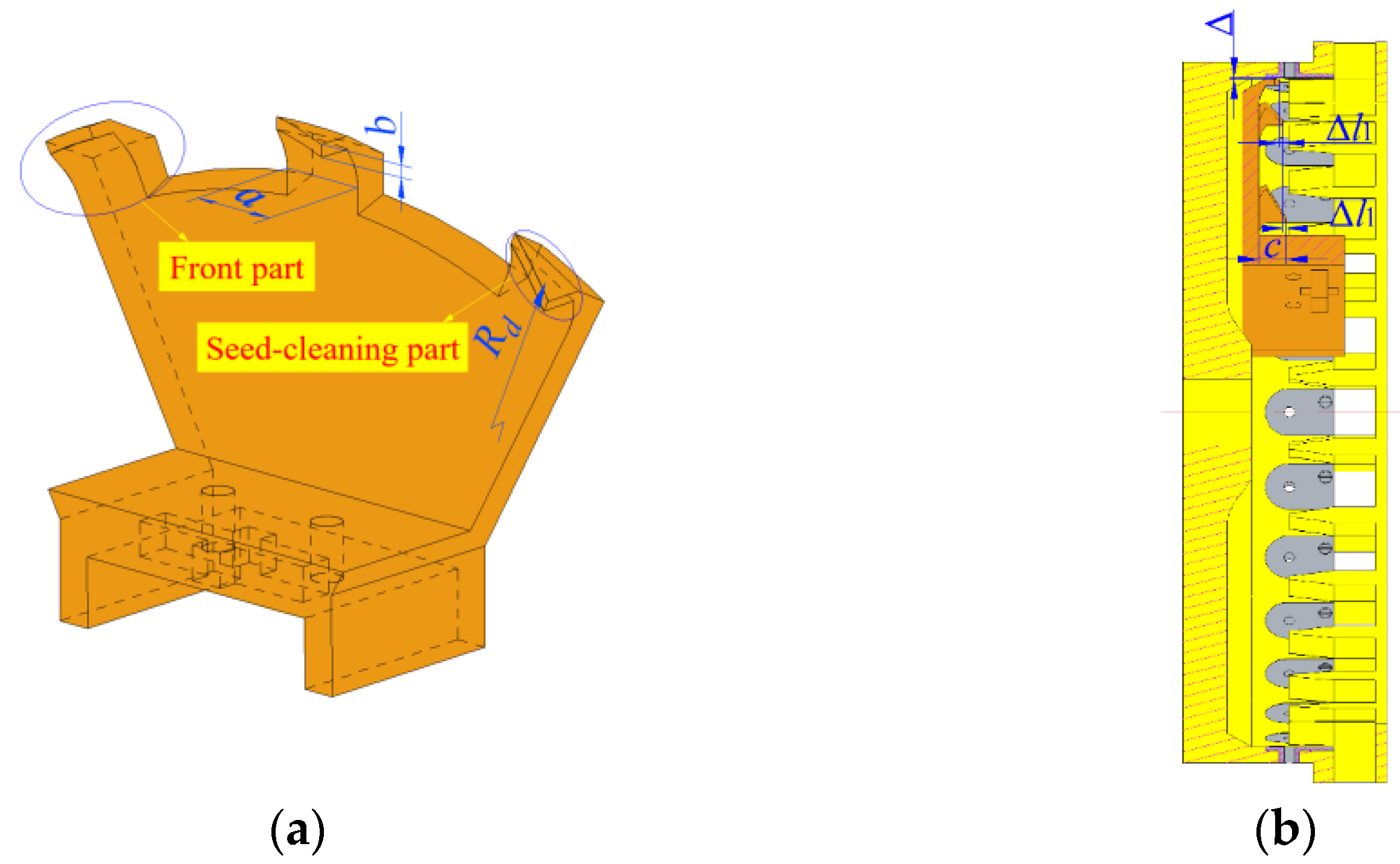
The seed-cleaning scraper is made of tough photosensitive resin. If the thickness of the seed-cleaning part is too thin, it is easily prone to large deformation due to insufficient strength during the working process and thus cannot meet the requirements of seed-cleaning operation. Meanwhile, if the seed-cleaning part is too thick, as can be seen from Figure 6b, it is relatively rotating with the seeding plate, and the distance from the front surface of the type hole is small; thus, during the seed-cleaning process, it is easy to appear that the cotton seeds do not drop in time and are pushed in between them, resulting in damage to the seeds and seed-cleaning scraper and sudden violent vibration of the seed-metering device, which leads to a large number of missed seedings. Therefore, the thickness of the seed-cleaning part should be selected as large as possible under the condition that the cotton seed cannot enter the area between the seed-cleaning part and the front surface of the type hole. To avoid cotton seeds getting into it, the distance between the lower surface of the seed-cleaning part and the inner wall of the annular groove should be less than half of the minimum thickness of the cotton seeds, and its calculation formula is b + ∆ < Tmin/2, where Tmin is the minimum thickness of the cotton seeds, mm. By substituting Tmin = 3.74 mm and ∆ = 0.3 mm into the above equation, the thickness of the seed-cleaning part is obtained as b < 1.57 mm. In order to enhance the manufacturing accuracy, the thickness of seed-cleaning part is selected as b = 1.5 mm.

Figure 6.
Schematic diagram of structure and installation of the seed-cleaning scraper. (a) Schematic diagram of the structure of the seed-cleaning scraper. (b) Schematic diagram of the relative position of the seed-cleaning scraper and the seeding plate. Note: a, front part’s width, mm; b, seed-cleaning part’s thickness, mm; Rd, top radius of the seed-cleaning scraper, mm; ∆, gap between the scraper top and annular groove inner wall, mm; c, extended length of the seed-cleaning part, mm; and ∆l1, increment of extended length of two adjacent segment scrapers, (°).
The extended length of the seed-cleaning part should ensure that the seeds removed by the seed-cleaning scraper can fall smoothly between the front surface of the type hole and the inner baffle of the seed-cleaning scraper; thus, the extended length of the seed-cleaning part must be greater than the cotton seeds width maximum, so that the extended length of the seed-cleaning part is obtained as c > 6.18 mm. As the extended length increases, the fall of the cotton seeds becomes smoother, but because the seed-cleaning part has a cantilever structure, a length that is too long easily leads to insufficient strength, and in order to take this into account, the seed-cleaning scraper can be adjusted along the seeding plate axially; the extended length was selected to be c = 8 mm. Moreover, in order to follow the method of gradually increasing the pushing force of the seed-cleaning scraper on the cotton seeds adsorbed on the suction hole’s end surface, the extended lengths of the three segment scrapers were increased in equal intervals, and the increment was chosen as ∆l1 = 1 mm; that is, the extended lengths of the three segment scrapers are 6, 7, and 8 mm, respectively.
- (3)
- Scraper Shape
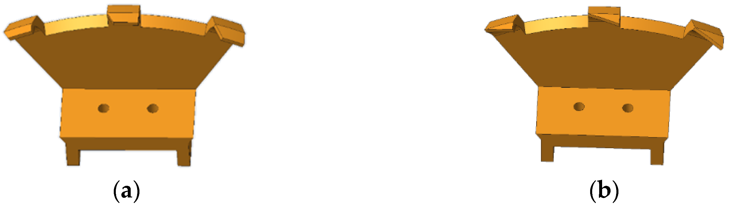
To probe the effect of different scraper shapes on seed-cleaning performance, two types of flat scrapers and sharp scrapers were designed, as shown in Figure 7, to conduct the relevant experimental research and determine a more suitable scraper shape.
Figure 7.
Scraper shapes: (a) flat scraper and (b) sharp scraper.
2.3.2. Design of the Seed-Disturbing Air Nozzle
The main function of the seed-disturbing air nozzle is to blow the cotton seeds gathered in the blind area of the seed-cleaning scraper operation out of the type hole, so as to facilitate the subsequent segment scraper to remove the re-adsorbed seeds; thus, it is the main component that can reduce the re-adsorption phenomenon. In order to gradually increase the seed-disturbing performance, the distances between the air-nozzle outlets of the double-outlet bifurcated air nozzle and the plane where the axes of the suction holes are located are gradually reduced.
Determination of the Inclination Angle of Outlet Section for the Seed-Disturbing Air Nozzle
The inclination angle of the outlet section axis of the seed-disturbing air nozzle (hereafter referred to as the inclination angle of the air nozzle) is directly related to the magnitude and direction of the airflow drag force on the cotton seeds that determines whether the cotton seeds can be blown out of the type hole. After the action of the seed-cleaning scraper, the cotton seed position is biased toward the inner side of the type hole, but the adsorption attitude is still random. In order to ensure that the cotton seeds can be blown out of the type hole smoothly under the high-speed airflow from the seed-disturbing air nozzle, its center of gravity should be on the right side of the central axis of the outlet section of the seed-disturbing air nozzle (hereinafter referred to as the axis of air nozzle), as shown in Figure 8.

Figure 8.
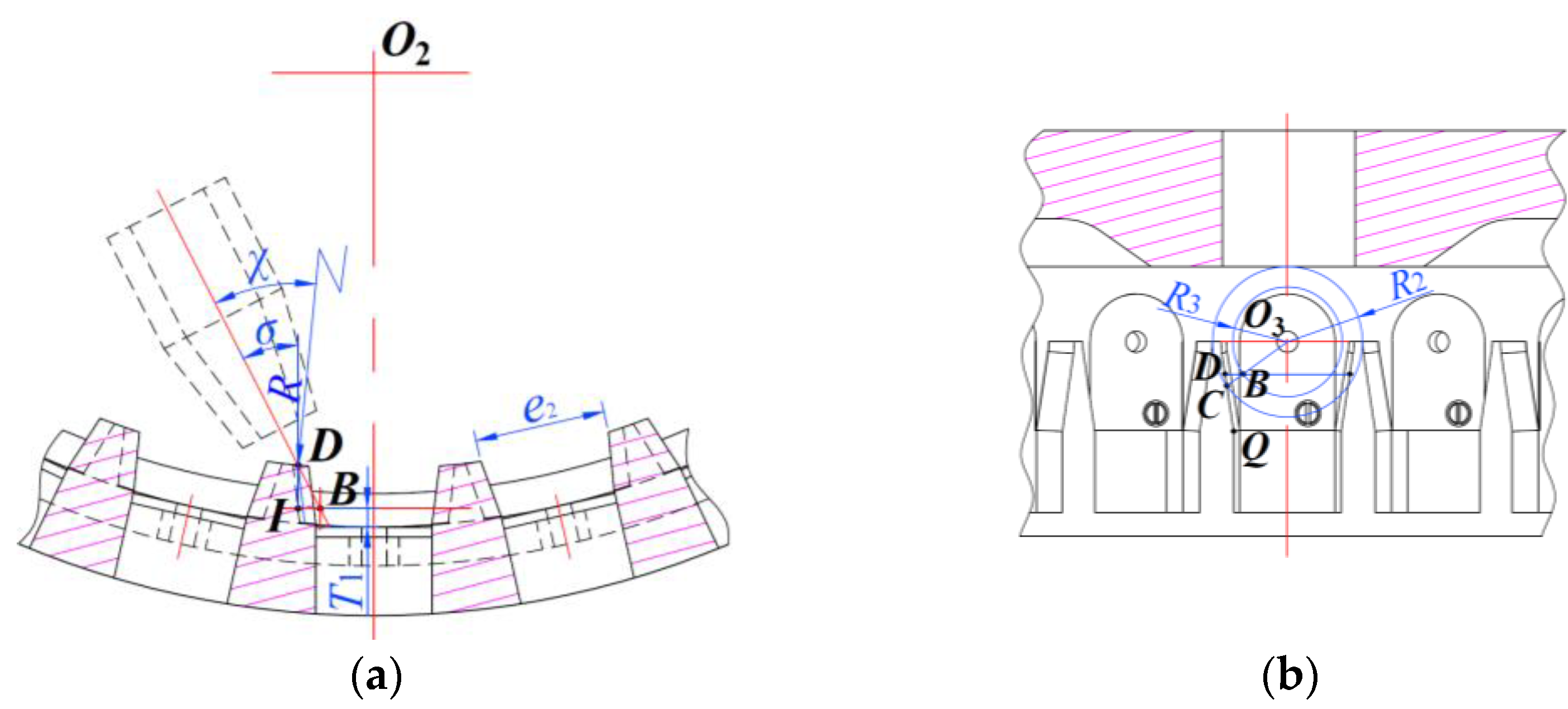
Design of the inclination angle of the central axis of the outlet section of the seed-disturbing air nozzle: (a) front view and (b) top view. Note: C, intersection of the outer circle and the outermost edge of the sidewall of the type hole; B, intersection of the straight line CO3 and the inner circle; D, intersection of a plane passing through point B and perpendicular to the central axis of the seeding plate with the outermost edge of the sidewall of the type hole; Q, highest point of the sidewall of the end surface of the filling hole; T1, distance between the gravity center of cotton seed and the lower bottom surface of corresponding type hole, mm; e2, width of the upper bottom edge of end surface of the filling hole, mm; R2, outer circle radius, mm; R3, inner circle radius, mm; σ, angle of air nozzle’s axis with the symmetry plane of the corresponding type hole, (°); and χ, angle between the line connecting the seeding plate center point and the intersection of air nozzle’s axis and the outermost edge of the sidewall of the type hole and the air nozzle’s axis in the plane passing through the air nozzle’s axis and perpendicular to the central axis of the seeding plate, (°).
It is assumed that the cotton seed’s center of gravity is located at the center of its triaxial dimension. Taking the suction hole center, O3, as the circle center, the maximum length of the cotton seeds is the radius R2 to make a circle, and its intersection with the outermost edge of the sidewall of the type hole is point C, as shown in Figure 8b. Then, taking the suction hole center, O3, as the circle center, the multiplication of the maximum length of the cotton seeds and the maximum value of the ratio of the distance between the width-thickness plane and the tip of the small head to the length of the cotton seed is the radius R3 to make a circle, and the intersection point B with the straight line CO3 is the limit position where the cotton seed center of gravity adsorbed on the suction hole’s end surface close to the sidewall of the type hole. The plane passing through point B and perpendicular to the axis of the seeding plate intersects with the axis of the seeding plate and the outermost edge of the sidewall of the corresponding type hole at points O2 and D, respectively, as shown in Figure 8a. To achieve the purpose of seed disturbance, the angle of air nozzle’s axis with the symmetry plane of the corresponding type hole, σ, should be less than the limit value in this critical state; the equation can be expressed as follows:
where lBI is the projected length of the line segment BD on the lower bottom surface of the type hole, mm.
The axis of the air nozzle should be determined so that the center of gravity of all cotton seeds is on its right side; thus, the distance between the cotton seed’s center of gravity and the lower bottom surface of the type hole in the above equation is chosen as half of the minimum thickness of cotton seeds, that is, T1 = Tmin/2. At the same time, the length of line segment BI is measured as lBI = 2.67 mm and substituted into Equation (8), together with H = 7 mm and Tmin = 3.74 mm, and the angle σ is obtained as σ < 27.50°. On the other hand, to avoid airflow loss, the angle σ should be greater than or equal to the chamfer of the sidewall of the type hole. Since the filling hole is approximately an inverted trapezoid, and its sidewall chamfer range is [6.27°, 7.47°], the angle σ should satisfy σ > 7.47°. The larger the angle σ, the greater the component of the airflow drag force on the cotton seeds along the lower bottom surface of the type hole, as this is conducive to the seeds being blown out from the inner side of the type hole; thus, the angle of air nozzle’s axis with the symmetry plane of the corresponding type hole is chosen as σ = 27°.
The second outlet of the seed-disturbing air nozzle is closer to the plane where the axes of the suction holes are located than the first outlet. The distance between the axis of the second outlet section of the seed-disturbing air nozzle and the plane where the axes of the suction holes are located is named the seed-disturbing distance, and in order to determine the optimal value, the installation position of the air nozzle is designed to be adjustable along the seeding plate axially. Under the above conditions, the position of the air nozzle’s axis varies with the change of the seed-disturbing distance. For ensuring that the center of gravity of the cotton seeds is always on the right of the axis of the air nozzle, the highest point of the sidewall of the end surface of the filling hole, Q, is used as the reference point to determine the air nozzle’s axis, as shown in Figure 8b. At this time, in the end plane of the filling hole, the angle of the line connecting the seeding plate center point and the point Q with the air nozzle’s axis is χ = σ + arcsin(e2/2R). By substituting e2 = 15.81 mm, R = 93 mm, and σ = 27° into the above equation, the angle of the line connecting the seeding plate center point and the point Q with the air nozzle’s axis is obtained as χ = 31.88°.
In order to determine the inclination angle of the air nozzle, in the plane passing through the air nozzle’s axis and perpendicular to the center axis of the seeding plate, take the seeding plate center point, O4, as the coordinate origin to establish a plane coordinate system, as shown in Figure 9.
Figure 9.
Analysis of the inclination angle of the central axis of the outlet section of the seed-disturbing air nozzle. Note: l1, first outlet section axis of the air nozzle; l2, the second outlet section axis of the air nozzle; S, intersection of the axis l1 and the lower bottom surface of the filling hole; V, intersection of the axis l2 and the lower bottom surface of the filling hole; N, midpoint of the largest arc of the baffle between the first and second segment scrapers; U, midpoint of the largest arc of the baffle between the second and third segment scrapers; P, intersection of the axis l1 with the inner circle of the seeding plate; W, intersection of the axis l2 with the inner circle of the seeding plate; and ϕ2, angle between the symmetrical centerline of the first and second segment scrapers and the horizontal axis of the seeding plate, (°).
In order to avoid mutual interference between the seed-cleaning scraper and the seed-disturbing air nozzle during the operation, the intersection between the first outlet section axis of the air nozzle, l1, and the lower bottom surface of the filling hole, S, is located on the symmetrical centerline of the first and second segment scrapers, NO4, and intersection between the second outlet section axis of the air nozzle, l2, and the lower bottom surface of filling hole, V, is located on the symmetrical centerline of the second and third segment scrapers, UO4. Meanwhile, it is known from the previous analysis that θSPO4 = θVWO4 = 180° − χ = 148.12°. The sine theorem can be used for triangle SPO4 and VWO4; the equation can be expressed as follows:
Substituting lPO4 = lWO4 = R=93 mm and lSO4 = lVO4≈R + H=100 mm into the above equation, we can obtain θPSO4 = θWVO4 = 29.34° and θSO4P = θVO4W = 2.54°. According to the above analysis, the angle between the symmetrical centerline of the first and second segment scrapers and the horizontal axis of the seeding plate is ϕ = 41.64°, and the angle between the symmetrical centerline of the second and third segment scrapers and the horizontal axis of the seeding plate is ϕ2 = 67.36°. After the calculation of the geometric relationship, the equations of the axes l1 and l2 can be obtained as follows:
Determination of Key Parameters for the Seed-Disturbing Air Nozzle
The design of the structural parameters of the seed-disturbing air nozzle is closely related to the seed-disturbing performance, which mainly includes the air-nozzle outlet’s diameter, d0; the double outlets spacing, ∆l2; and the outlet position. In this study, the conical air nozzle was used for the seed disturbing, and after referring to the research of Ni et al. and Zhang [2,28], we noted that the air-nozzle outlet’s diameter, d0, should be smaller than the average length of the cotton seeds, so the outlet diameter of d0 = 5 mm was chosen. Meanwhile, in order to meet the operation mode of gradually increasing the seed-disturbing performance, the double outlets spacing was chosen to be ∆l2 = 2 mm.
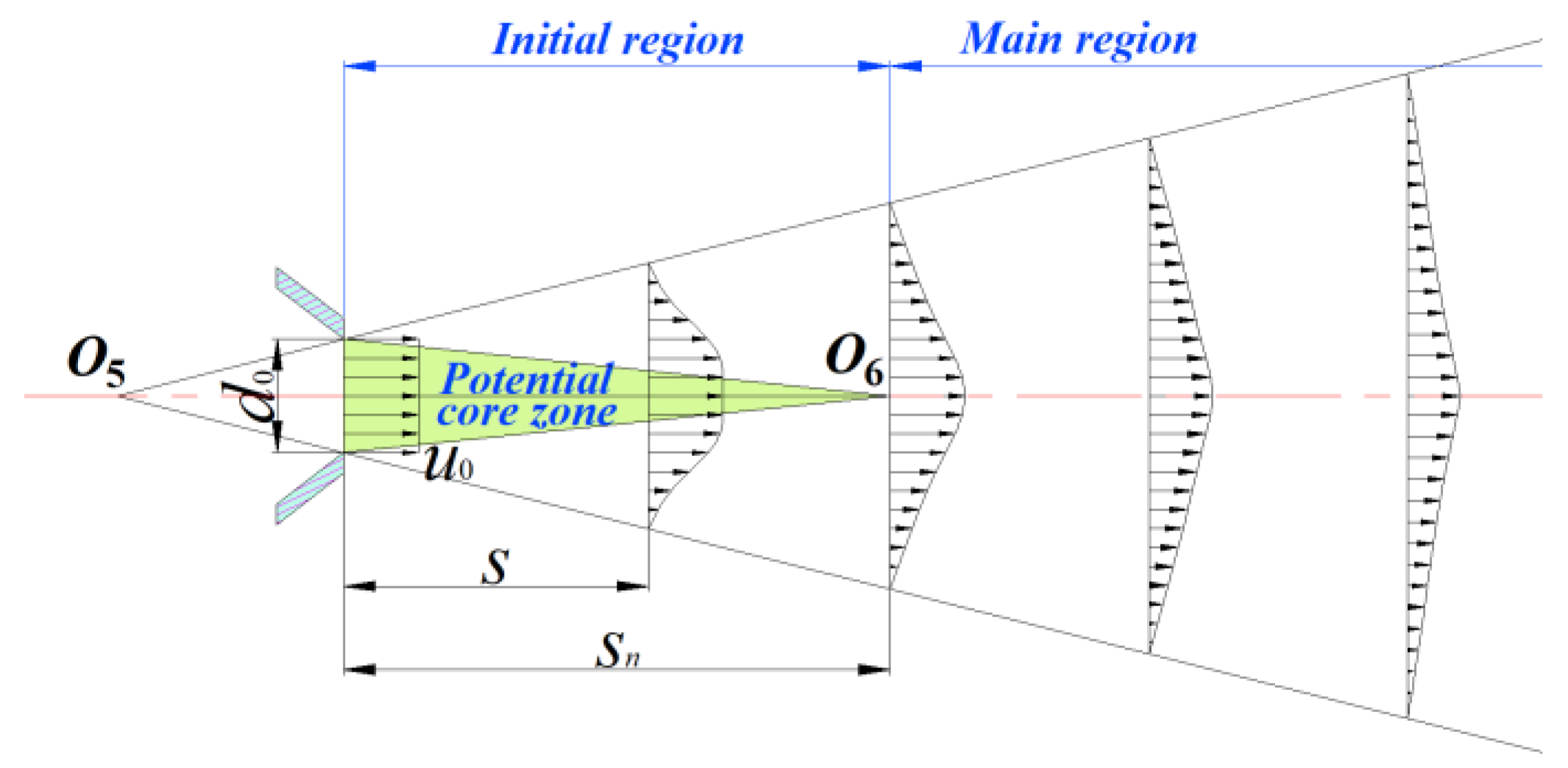
The high-speed airflow is injected into the inner cavity of the seeding plate from the outlet of seed-disturbing air nozzle, which belongs to the gas submerged jet, and its flow structure is shown in Figure 10 [29,30]. Assuming that the airflow at the outlet of the air nozzle is uniformly ejected at a specific velocity, u0, due to the continuous exchange of momentum and mass between the jet gas and the surrounding medium, the boundary layer of the jet gradually diffuses outward to form a conical flow field, and in the center of the flow field, there exists a potential core zone where the airflow moves at the initial velocity, u0, as shown in Figure 10. Since the average velocity of the airflow section in the submerged jet field decreases as its distance from the air nozzle’s outlet increases, in order to make the airflow smoothly disturb the cotton seeds and reduce losses, the distance between the intersection of the air nozzle’s axis and the seeding plate and the center of the air nozzle’s outlet should be within the potential core zone; the equation can be expressed as follows:
where s is the distance between the intersection of the air nozzle’s axis and the seeding plate and the center of the air nozzle’s outlet, mm; sn is the length of the potential core zone, mm; and a is the turbulence coefficient.

Figure 10.
Structure diagram of gas submerged jet. Note: O5, intersection of the outer boundary of the jet; O6, the end of the potential core zone; d0 is the air-nozzle outlet’s diameter, mm; u0, initial velocity, m·s; s, distance between the intersection of the air nozzle’s axis and the seeding plate and the center of the air nozzle’s outlet, mm; and sn, length of the potential core zone, mm.
In engineering calculations, the turbulence coefficient for axisymmetric convergent nozzle is generally taken as a = 0.066–0.071 [30]. In this paper, the turbulence coefficient of a = 0.07 is selected and substituted into Equation (11) together, with d0 = 5 mm, and the distance between the intersection of the air nozzle’s axis and the seeding plate and the center of the air nozzle’s outlet is obtained as s < 24 mm. In order to make the airflow drag force on the cotton seeds larger, the distance, s, should be as small as possible under the condition that the space position does not interfere with other components. In this study, the center position of the air nozzle’s outlet was selected on the circle of a seeding plate with a radius of R4 = 88 mm. At this time, the distance between the intersection of the air nozzle’s axis and the seeding plate and the center of the air nozzle’s outlet was calculated as s = 14.08 mm, which meets the normal operation of the seed-disturbing air nozzle.
2.4. Seed-Cleaning Performance Test of Inside-Filling Pneumatic Precision Seed-Metering Device
2.4.1. Test Materials and Equipment
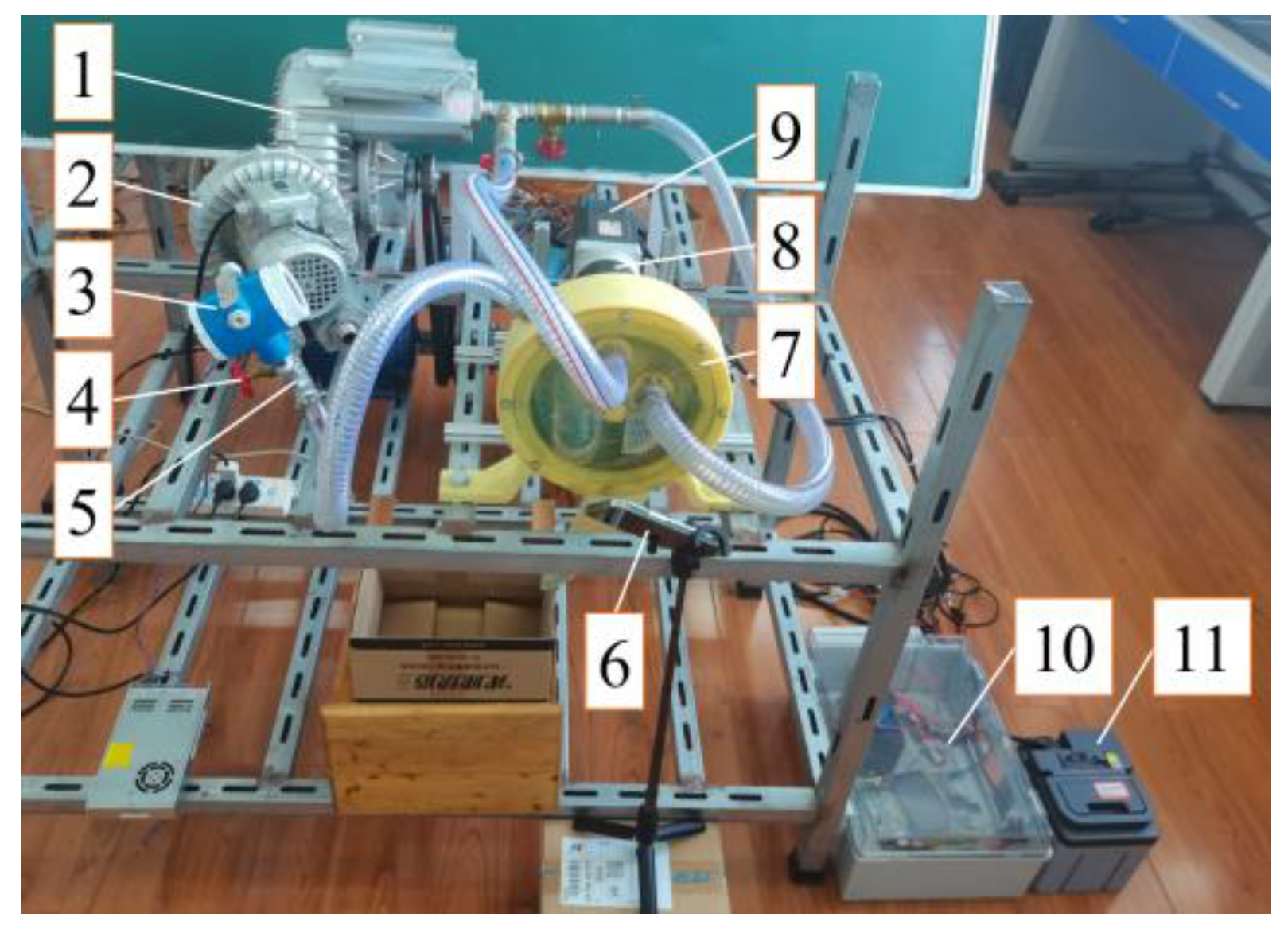
The cotton seed variety E’kangmian-10 was selected to be the test material, with a 1000 grain mass of 94.5 g (measured by digital electronic scale, Dongguan City Nancheng Changxie Electronic Products Factory, Dongguan, China, I-2000 type, accuracy of 0.1 g) and a natural repose angle of 34.82°. A self-built seed-metering device performance test bench was adopted for the tests, as shown in Figure 11. The seeding plate was driven in a clockwise rotation via a DC motor (Beijing Times Brilliant Technology Co., Ltd., Beijing, China, 86BL130S78-430TK9 type), and its speed can be infinitely adjusted by the control system. The three pipes connected to the fans and the seed-metering device were all installed with regulating valves and tee joints. The detection end of the digital pressure gauge was threaded with the tee joint, which can detect and display the pressure of the pipes in real time. The inlet and outlet pressure of the seed-metering device can be controlled by adjusting the regulating valves. The iPhone camera (240 fps) was facing the seed-carrying zone to record the adsorption state of cotton seeds on the suction hole’s end surfaces after the action of the seed-cleaning mechanism in real time.
Figure 11.
Platform of seed-metering device performance test. (1) Fan I, (2) fan II, (3) digital pressure gauge, (4) regulating valve, (5) tee joint, (6) iPhone camera, (7) inside-filling pneumatic seed-metering device, (8) planetary gear retarder, (9) DC motor, (10) control system, and (11) lithium battery.
2.4.2. Test Method and Evaluation Indexes
To investigate the impact of seed-cleaning mechanism on seed-cleaning effect, the seeding plate speed was adjusted to 29.76 r/min (corresponding to the forward speed as 10 km/h) and negative pressure was adjusted to −3000 Pa. Through the pre-test, it was found that, before the suction holes were rotated into the area where the seed-cleaning mechanism was located, there were multiple cotton seeds adsorbed on their end surfaces, so the adsorption state of the cotton seeds on the end surfaces of suction holes after the action of the seed-cleaning mechanism was caused by the seed-cleaning mechanism. Under the stable working condition, the camera was used to record the stable adsorption state of cotton seeds in the seed-carrying zone after the action of the seed-cleaning mechanism. One video was recorded for each group of experiments. Randomly intercept 251 consecutive suction holes in the video and record the number of cotton seeds adsorbed on their end surfaces separately. When no cotton seed was adsorbed on the end surface of the suction hole, we considered that to be excessive cleaning, and missing cleaning was when 2 or more cotton seeds were adsorbed. Taking the single seed rate, S0; excessive cleaning rate, E0; and missing cleaning rate, M0, as evaluation indexes, the calculation formula is as follows:
where n1 is the suction holes number of one cotton seed adsorbed on the end surface; n2 is the suction holes number without cotton seed adsorbed on the end surface; n3 is the suction holes number of 2 or more cotton seeds adsorbed on the end surface; and N is suction holes total number.
2.4.3. Test Design
The preliminary analysis and pre-tests found that the key factors influencing the seed-cleaning effect were the seed-cleaning scraper shape, the distance between the front end of the seed-cleaning part of the seed-cleaning scraper and the plane where the axes of the suction holes are located (hereinafter referred to as the seed-cleaning distance), seed-disturbing distance, and seed-disturbing pressure. Therefore, the seed-cleaning performance tests were carried out with the above four factors as the impact factors.
- (1)
- The seed-disturbing air nozzle was removed, and the single-sided seed-cleaning scraper was adopted as the seed-cleaning mechanism. The single-factor comparison test was conducted for the flat and sharp seed-cleaning scrapers, as shown in Figure 7, under different seed-cleaning distances to investigation the influence law of scraper shape on seed-cleaning effect and obtain the optimal scraper shape. The seed-cleaning distance was set as 0.5–4.5 mm, with an interval of 0.5 mm. Each group of tests was repeated 3 times, and the mean values were recorded to be the evaluation indexes.
- (2)
- The optimal seed-cleaning scraper shape obtained from the above test was combined with the seed-disturbing air nozzle as the combined seed-cleaning mechanism of the seed-metering device. A Box–Behnken Design test was executed, taking the seed-cleaning distance, seed-disturbing distance, and seed-disturbing pressure as impact factors for exploring the influencing of the impact factors on the evaluation indexes. From the previous pre-test, it was found that the seed-cleaning performance was good when the seed-cleaning distance, seed-disturbing distance, and seed-disturbing pressure were set to 0.5–4.5 mm, 4.0–8.0 mm, and 200–3000 Pa, respectively. Moreover, the test levels for the test factors are shown in Table 1. A total of 17 groups were tested. Each group was duplicated 3 times, and the mean values were recorded to be evaluation indexes.
 Table 1. Box–Behnken test factors and levels.
3. Results and Discussion
3.1. Single-Factor Comparison Test on the Shape of the Seed-Cleaning Scraper
The results of the single-factor comparison test are shown in Table 2.
Table 2.
Single-factor comparison test results.
As can be seen from Table 2, no matter what seed-cleaning scraper shape was adopted, with the seed-cleaning distance increasing, the single seed rate tended to increase first and then decrease, the missing cleaning rate gradually increased, and the excessive cleaning rate gradually decreased. When the seed-cleaning distance was 0.5 mm, the excessive cleaning rates were greater than 13.5%. At this time, the area of the suction hole’s end surface occupied by the seed-cleaning scraper was larger, thus affecting the normal adsorption of cotton seeds. With the increase of seed-cleaning distance, the excessive cleaning rate decreased sharply and the single-seed rate increased rapidly; when the seed-cleaning distance increased to 1.5 mm, the optimal seed-cleaning performance was achieved if the sharp seed-cleaning scraper was used; and the single seed rate, missing cleaning rate, and excessive cleaning rate were 93.25%, 5.03%, and 1.72%, respectively. Meanwhile, when the seed-cleaning distance increased to 2 mm, the optimal seed-cleaning performance was achieved if the flat seed-cleaning scraper was adopted, and the single seed rate, missing cleaning rate, and excessive cleaning rate were 92.11%, 5.32%, and 2.57%, respectively. With the further increase of the seed-cleaning distance, the excessive cleaning rate decreased slowly, while the missing cleaning rate increased rapidly, and the single seed rate decreased. When comparing the optimal seed-cleaning performance under the use of the above two scrapers, it can be seen that, when the scraper was adopted as the only seed-cleaning mechanism, the sharp scraper gave a better seed-cleaning performance than the flat scraper, and their missing cleaning rates were all greater than 5%. Since the re-adsorbed seeds have a greater impact on the final seeding effect of the seed-metering device, the sharp scraper can be combined with the seed-disturbing air nozzle subsequently to further improve the seed-cleaning performance.
3.2. Box–Behnken Test on the Combined Seed-Cleaning Mechanism
3.2.1. Significance Analysis and Regression Model
The protocol and results of the Box–Behnken test are shown in Table 3.
Table 3.
Box–Behnken test protocol and results.
The Design-Expert 10.0.4 software was employed to conduct further significance analysis, and the results presented in Table 4. From the table, it can be seen that the terms of the regression models were all highly significant and the terms of lack of fit were all insignificant, thus indicating that the regression equations fitted well with the actual situation. For the regression equations of single seed rate, all the terms were highly significant. For the regression equations of missing cleaning rate, the interaction term X1X3 and all the linear terms, X1, X2, and X3, were highly significant; the interaction term X1X2 and quadratic terms X12 and X32 were significant; and the remaining terms were insignificant. For the regression equations of excessive cleaning rate, the interaction term X1X2 and quadratic term X22 were significant; the remaining terms were highly significant. Moreover, the order of each test factor affecting the evaluation indexes was as follows: seed-cleaning distance > seed-disturbing pressure > seed-disturbing distance. The quadratic regression equations of evaluation indexes with test factors are as follows:
Table 4.
Variance analysis of Box–Behnken test results.
3.2.2. Effect of Interaction Factors on Seed-Cleaning Performance
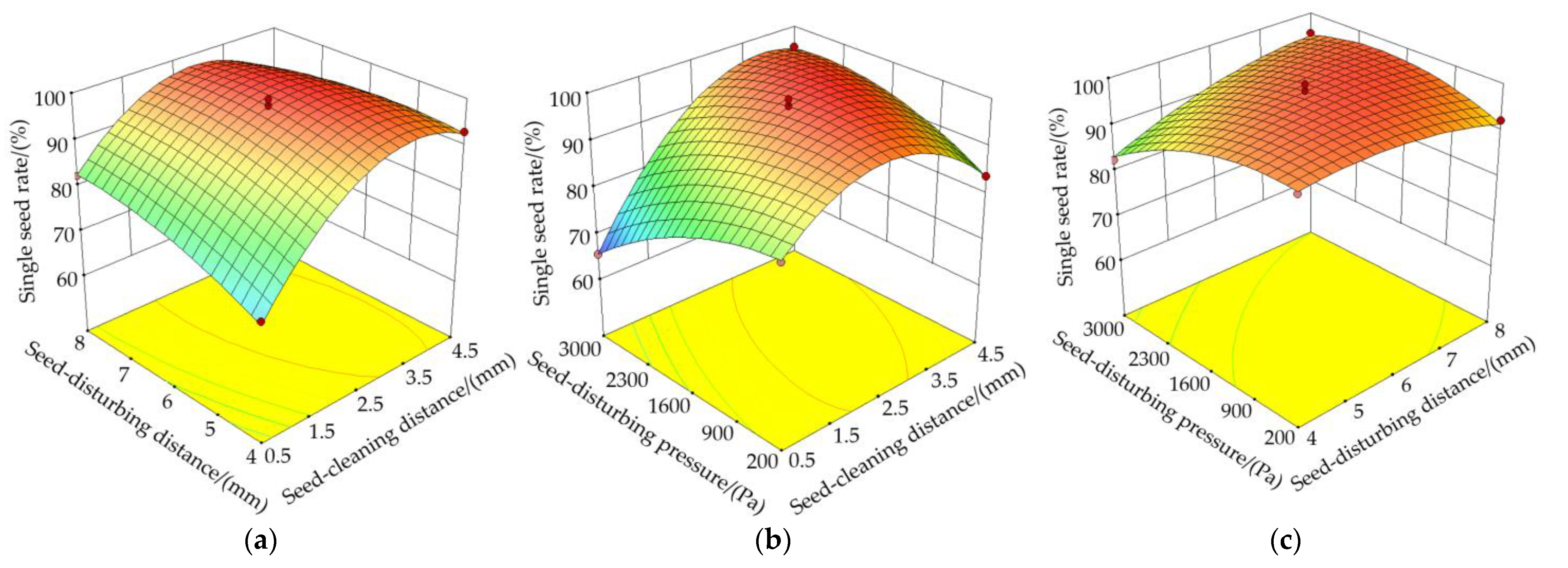
So as to visually analyze the impact of the interaction factors on the seed-cleaning performance, the descending dimension method was used to adjust the coding of any of the three impact factors to zero, and the corresponding response surface diagrams of the interaction of the other two impact factors on the single seed rate and missing cleaning rate were plotted, as shown in Figure 12.
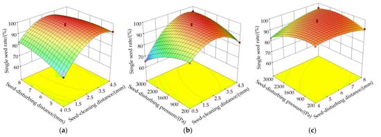
Figure 12.
Response surface of interaction factors effects on single seed rate and missing cleaning rate: (a) S0(X1, X2, 0), (b) S0(X1, 0, X3), (c) S0(0, X2, X3), (d) M0(X1, X2, 0), (e) M0(X1, 0, X3), and (f) M0(0, X2, X3).
As can be seen from Figure 12a,d, under the condition that the seed-disturbing pressure was 1600 Pa and the seed-disturbing distance was constant, the missing cleaning rate gradually increased with the seed-cleaning distance increasing, and the single seed rate was the first to increase and then decrease. When the seed-cleaning distance was small, the area occupied by the seed-cleaning scraper at the end surface of the suction hole was larger, and this easily led to the phenomenon of cotton seeds’ excessive cleaning due to the insufficient adsorption force; and at this time, the missing cleaning rate was small and the single seed rate was low. With the increase of seed-cleaning distance, the phenomenon of excessive cleaning was reduced, the missing cleaning rate slowly increased, and the single seed rate relatively increased. However, when the seed-cleaning distance was too large, the seed-cleaning scraper effect was weak and the adsorption force on the cotton seed was strong, and this easily led to the phenomenon of missing cleaning, thus resulting in a lower single seed rate. Under the condition that the seed-disturbing pressure was 1600 Pa and the seed-cleaning distance was constant, the missing cleaning rate gradually increased with the increase of the seed-disturbing distance, and the single seed rate was the first to increase and then decrease. When the seed-disturbing distance was small, the cotton seeds squeezed into the inner side of the type hole were easier to be cleaned by the seed-disturbing air nozzle, resulting in a more excessive cleaning phenomenon. With the increase of the seed-disturbing distance, the phenomenon of excessive cleaning decreased, but when the seed-disturbing distance was too large, it was difficult for the air nozzle to blow the cotton seeds out of the type hole to facilitate the alternate operation of the subsequent seed-cleaning mechanism, so the seed-disturbing quality decreased, the missing cleaning rate increased, and the single seed rate relatively decreased.
As can be seen from Figure 12b,e, under condition that the seed-disturbing distance was 6.0 mm and the seed-disturbing pressure was constant, the missing cleaning rate gradually increased with the seed-cleaning distance increasing, and single seed rate was the first to increase and then decrease. Under the condition that the seed-disturbing distance was 6.0 mm and the seed-cleaning distance was constant, the missing cleaning rate gradually decreased with the seed-disturbing pressure increasing, and single seed rate was the first to increase and then decrease. When the seed-disturbing pressure was too small, it was difficult to blow the seeds out of the type hole with a low airflow, and this led to a greater missing cleaning phenomenon, and as the seed-disturbing pressure increased, the missing cleaning rate decreased, while when the seed-disturbing pressure was too large, the seeds squeezed into the inner side of the type hole were easy to be cleaned by the high-speed airflow from air nozzle; thus, the excessive cleaning phenomenon increased and the single seed rate decreased.
As can be seen from Figure 12c,f, under the condition that the seed-cleaning distance was 2.5 mm and the seed-disturbing pressure was constant, the missing cleaning rate gradually increased with the seed-disturbing distance increasing, and the single seed rate was the first to increase and then decrease. Under the condition that the seed-cleaning distance was 2.5 mm and the seed-disturbing distance was constant, the missing cleaning rate gradually decreased with the seed-disturbing pressure increasing, and the single seed rate was the first to increase and then decrease. Meanwhile, the variation magnitude of response surface in Figure 12 indicated that the influence of the seed-cleaning distance on the single seed rate and missing cleaning rate was significantly greater than that of the seed-disturbing pressure and seed-disturbing distance, as was consistent with the previous variance analysis.
3.2.3. Parameter Optimization
So as to obtain the best combination of operating parameters for the above test factors, the single seed rate maximization and missing and excessive cleaning rate minimization were set as the optimization objectives, the range of test factors were set as boundary conditions, and the optimal solution was performed for above regression models. The objective functions and boundary conditions can be expressed as follows:
The results of the optimal solution are as follows: 3.1 mm for seed-cleaning distance, 6.2 mm for seed-disturbing distance, and 2165 Pa for seed-disturbing pressure. Its corresponding seed-cleaning performance indexes were as follows: 98.46% for single seed rate, 1.54% for missing cleaning rate, and 0 for excessive cleaning rate. To verify the reliability of the optimized parameters, the seed-cleaning performance test was carried out based on the optimized parameter values. The validation tests were repeated three times, and the mean values of the evaluation indexes were as follows: 98.03% for single seed rate, 1.42% for missing cleaning rate, and 0.55% for excessive cleaning rate. Thus, they are basically in agreement with the predicted results.
3.3. Discussion
In comparison with the optimal seed-cleaning effects under the single-sided seed-cleaning scrapers of flat and sharp shape, respectively, the combined double-sided seed-cleaning mechanism reduced by 3.90 and 3.61 percentage points the missing cleaning rate, reduced by 2.02 and 1.17 percentage points the excessive cleaning rate, and increased by 5.92 and 4.78 percentage points the single seed rate. In view of the structural characteristics of the inside-filling pneumatic seed-metering device, the seed-cleaning scraper can only remove the cotton seeds on one side of the suction hole’s end surface, while the cotton seeds tend to gather on the other side of the suction hole’s end surface. Moreover, if the seed-cleaning distance is decreased to increase the seed-cleaning strength, it is easy to reduce the missing cleaning rate and increase the excessive cleaning rate at the same time, thus making it difficult to achieve a high seed-cleaning quality. The combined seed-cleaning mechanism combining a seed-cleaning scraper and seed-disturbing air nozzle can realize alternate seed cleaning on both sides of the suction hole’s end surface and effectively reduce the phenomenon of missing cleaning. In addition, compared with the single-sided seed-cleaning scraper, the combined seed-cleaning mechanism can improve the excessive cleaning phenomenon by appropriately increasing the seed-cleaning distance, thereby improving the seed-cleaning performance.
This study demonstrates the feasibility of using the double-sided seed-cleaning mechanism combining seed-cleaning scraper and seed-disturbing air nozzle to improve the seed-cleaning performance of an inside-filling pneumatic precision seed-metering device. The design of the combined double-sided seed-cleaning mechanism and the influence of the relevant test factors on the seed-cleaning performance obtained in the paper can act as a reference on the design and parameter optimization of the seed-cleaning mechanism of the precision seed-metering device. Nevertheless, this study still has some shortcomings, such as considering only one variety of cotton seeds. The optimal operating parameters for different varieties of cotton seeds require further investigation.
4. Conclusions
- (1)
- Aiming to address the problem of the poor seed-cleaning performance of the inside-filling pneumatic cotton precision seed-metering device, a double-sided seed-cleaning mechanism combining a seed-cleaning scraper and seed-disturbing air nozzle was designed. The key structure and parameters of the seed-cleaning mechanism were determined by combining theoretical analysis and operational requirements.
- (2)
- The results of single-factor comparison test revealed that, no matter what shape of seed-cleaning scraper was adopted for the seed-metering device, the missing cleaning rates under the corresponding optimal seed-cleaning effect were greater than 5%, and the sharp scraper gave a better seed-cleaning performance than the flat scraper.
- (3)
- The results of the Box–Behnken Design test indicated that all the test factors were highly significant on evaluation indexes. The order of each test factor affecting the evaluation indexes was as follows: seed-cleaning distance > seed-disturbing pressure > seed-disturbing distance. The optimal combination of parameters was as follows: 3.1 mm for seed-cleaning distance, 6.2 mm for seed-disturbing distance, and 2165 Pa for seed-disturbing pressure. Moreover, the evaluation indexes of the validation tests based on the optimized parameter values were as follows: 98.03% for single seed rate, 1.42% for missing cleaning rate, and 0.55% for excessive cleaning rate.
- (4)
- In comparison with the optimal seed-cleaning effects under the single-sided seed-cleaning scrapers of flat and sharp shape, respectively, the combined double-sided seed-cleaning mechanism reduced 3.90 and 3.61 percentage points in missing cleaning rate, reduced 2.02 and 1.17 percentage points in excessive cleaning rate, and increased 5.92 and 4.78 percentage points in single seed rate, indicating that the combined double-sided seed-cleaning mechanism can effectively improve the seed-cleaning effect of inside-filling pneumatic seed-metering device.
Author Contributions
Conceptualization, M.H. and J.X.; methodology, M.H.; software, M.H., M.Z., Z.L. and D.X.; validation, M.H., J.X., M.Z., Z.L. and D.X.; formal analysis, M.H.; investigation, M.H., M.Z., Z.L. and D.X.; resources, M.H.; data curation, M.H.; writing—original draft preparation, M.H.; writing—review and editing, M.H. and J.X.; visualization, M.H.; supervision, J.X.; project administration, J.X.; funding acquisition, J.X. All authors have read and agreed to the published version of the manuscript.
Funding
This research was funded by the Research Funds for Public Welfare Industries (Agriculture) (Grant No. 201503136) and National Key Research and Development Program (Grant No. 2017YFD0301303).
Institutional Review Board Statement
Not applicable.
Data Availability Statement
The data presented in this study are available upon demand from the first author at (hmj_oy@webmail.hzau.edu.cn).
Acknowledgments
The authors would like to thank their schools and colleges, as well as the funding of the project. All supports and assistance are sincerely appreciated.
Conflicts of Interest
The authors declare no conflict of interest.
References
- Mao, S.C.; Li, Y.B.; Dong, H.Z.; Bie, S.; Lin, Y.Z.; Dong, H.L. Cotton Cultivation in China, 1st ed.; Shanghai Science and Technology Press: Shanghai, China, 2013; pp. 55–65. [Google Scholar]
- Ni, X.D.; Xu, G.J.; Wang, Q.; Peng, X.R.; Wang, J.; Hu, B. Design and Experiment of Pneumatic Cylinder Array Precision Seed-metering Device for Cotton. Trans. Chin. Soc. Agric. Mach. 2017, 48, 58–67. [Google Scholar]
- Xu, G.J. Design and Experiment of Pneumatic Cylinder Array Precision Seed-Metering Device for Cotton. Master’s Thesis, Shihezi University, Shihezi, China, 2018. [Google Scholar]
- Braunack, M.V.; Johnston, D.B.; Price, J.; Gauthier, E. Soil temperature and soil water potential under thin oxodegradable plastic film impact on cotton crop establishment and yield. Field Crop. Res. 2015, 184, 91–103. [Google Scholar] [CrossRef]
- Sun, Y.T.; Tian, L.Z.; Shang, S.Q.; Yang, R.B.; Wang, Y.Y.; Zhao, J.L. Experimental research on inside-filling metering device for peanut seeder. Trans. CSAE 2012, 28, 84–89. [Google Scholar]
- China Academy of Agricultural Mechanization Science. Agricultural Machinery Design Manual, 1st ed.; China Agricultural Science and Technology Press: Beijing, China, 2007; pp. 343–345. [Google Scholar]
- Du, X.; Liu, C.L.; Jiang, M.; Zhang, F.Y.; Yuan, H.; Yang, H.X. Design and experiment of self-disturbance inner-filling cell wheel maize precision seed-metering device. Trans. CSAE 2019, 35, 23–34. [Google Scholar]
- Liu, J.; Cui, T.; Zhang, D.X.; Yang, L.; Shi, S. Mechanical-pneumatic combined corn precision seed-metering device. Trans. Chin. Soc. Agric. Mach. 2012, 43, 43–47. [Google Scholar]
- Li, B.F. Agricultural Machines, 1st ed.; China Agricultural Press: Beijing, China, 2003; pp. 61–62. [Google Scholar]
- Jia, H.L.; Chen, Y.L.; Zhao, J.L.; Wang, J.X.; Guo, M.Z.; Zhuang, J. Design and experiment of pneumatic-mechanical combined precision metering device for soybean. Trans. Chin. Soc. Agric. Mach. 2018, 49, 75–86. [Google Scholar]
- Yazgi, A.; Degirmencioglu, A. Optimisation of the seed spacing uniformity performance of a vacuum-type precision seeder using response surface methodology. Biosyst. Eng. 2007, 97, 347–356. [Google Scholar] [CrossRef]
- Xing, H.; Wang, Z.M.; Luo, X.W.; He, S.Y.; Zang, Y. Mechanism modeling and experimental analysis of seed throwing with rice pneumatic seed metering device with adjustable seeding rate. Comput. Electron. Agric. 2020, 178, 105697. [Google Scholar] [CrossRef]
- Wang, B.L.; Na, Y.; Liu, J.; Wang, Z.M. Design and Evaluation of Vacuum Central Drum Seed Metering Device. Appl. Sci. 2022, 12, 2159. [Google Scholar] [CrossRef]
- Li, B.H.; Ahmad, R.; Qi, X.D.; Li, H.; Nyambura, S.M.; Wang, J.F.; Chen, X.; Li, S.B. Design Evaluation and Performance Analysis of a Double-Row Pneumatic Precision Metering Device for Brassica chinensis. Sustainability 2021, 13, 1374. [Google Scholar] [CrossRef]
- Sun, X.P.; Li, H.; Qi, X.D.; Nyambura, S.M.; Yin, J.Q.; Ma, Y.L.; Wang, J.S. Performance Parameters Optimization of a Three-Row Pneumatic Precision Metering Device for Brassica chinensis. Agronomy 2022, 12, 1011. [Google Scholar] [CrossRef]
- Xu, J.; Hou, J.W.; Wu, W.B.; Han, C.Y.; Wang, X.M.; Tang, T.; Sun, S.L. Key Structure Design and Experiment of Air-Suction Vegetable Seed-Metering Device. Agronomy 2022, 12, 675. [Google Scholar] [CrossRef]
- Shi, S.; Zhou, J.L.; Liu, H.; Fang, H.M.; Jian, S.C.; Zhang, R.F. Design and experiment of pneumatic precision seed-metering device with guided assistant seed-filling. Trans. Chin. Soc. Agric. Mach. 2019, 50, 61–70. [Google Scholar]
- Shi, S.; Liu, H.; Zhou, J.L.; Jian, S.C.; Zhang, R.F. Optimization and Experiment of Pneumatic Seed Metering Device with Guided Assistant Filling Based on EDEM-CFD. Trans. Chin. Soc. Agric. Mach. 2020, 51, 54–66. [Google Scholar]
- Li, Z.D.; Yang, W.C.; Wu, Y.Y.; He, S.; Wang, W.W.; Chen, L.Q. Performance analysis and experiments of seed filling assisted by groove-tooth of pneumatic disc precision metering device for rapeseed. Trans. CSAE 2020, 36, 57–66. [Google Scholar]
- Lai, Q.H.; Ma, W.P.; Liu, S.; Su, W.; Zhang, Z.H. Simulation and experiment on seed-filling performance of pneumatic disc seed-metering device for mini-tuber. Trans. Chin. Soc. Agric. Mach. 2017, 48, 44–53. [Google Scholar]
- Hu, M.J.; Xia, J.F.; Zheng, K.; Du, J.; Liu, Z.Y.; Zhou, M.K. Design and Experiment of Inside-filling Pneumatic High Speed Precision Seed-metering Device for Cotton. Trans. Chin. Soc. Agric. Mach. 2021, 52, 73–85. [Google Scholar]
- Li, J.J.; Zhang, H.P.; Bi, X.S.; Wang, J.; Hu, B.; Li, S.Z. Simulation analysis and test on the filling performance of rotary type-hole precision seed-metering device for cotton. Trans. CSAE 2020, 36, 38–49. [Google Scholar]
- Liu, Y.Q.; Liu, L.J.; Zhao, Z.B.; Zhao, J.H.; Cui, W. Design and Experiment on Plant Seedling Device for Vegetable Seedling Seeder. Trans. Chin. Soc. Agric. Mach. 2018, 49, 83–91. [Google Scholar]
- Qi, B.; Zhang, D.X.; Liu, Q.W.; Yang, L.; Shi, S.; Cui, T. Design and experiment of cleaning performance in a centralized pneumatic metering device for maize. Trans. CSAE 2015, 31, 20–27. [Google Scholar]
- Ding, L.; Yang, L.; Zhang, D.X.; Cui, T. Parametric design and test of seed cleaning mechanism of air-suction maize seed-metering device. Trans. Chin. Soc. Agric. Mach. 2019, 50, 47–56. [Google Scholar]
- Li, Y.H.; Yang, L.; Zhang, D.X.; Cui, T.; He, X.T.; Hu, H. Design and test of double-side cleaning mechanism for air-suction maize seed-metering device. Trans. Chin. Soc. Agric. Mach. 2021, 52, 29–39. [Google Scholar]
- Wang, J.K. Study on Motion Characteristics of Cottonseed in Dibbler and Mechanism of Clamping Seeding. Ph.D. Thesis, Northwest A&F University, Yangling, China, 2010. [Google Scholar]
- Zhang, B.P. Seeding Machine Design Principles, 1st ed.; Machinery Industry Press: Beijing, China, 1982; pp. 316–317. [Google Scholar]
- Cai, Z.J.; Long, T.Y. Fluid Mechanics Pumps and Fans, 4th ed.; China Construction Industry Press: Beijing, China, 1999; pp. 156–157. [Google Scholar]
- Jiang, Y.; Shi, S.Y.; Niu, Y.S. Space Launch Science and Technology Launch Gas Dynamics, 1st ed.; Beijing Institute of Technology Press: Beijing, China, 2015; pp. 13–14. [Google Scholar]


Publisher’s Note: MDPI stays neutral with regard to jurisdictional claims in published maps and institutional affiliations. |
© 2022 by the authors. Licensee MDPI, Basel, Switzerland. This article is an open access article distributed under the terms and conditions of the Creative Commons Attribution (CC BY) license (https://creativecommons.org/licenses/by/4.0/).