Abstract
In order to satisfy the soil preparation requirements of a rapeseed combined transplanter in the middle-lower Yangtze River region in China where rice–rapeseed rotation cropping system was performed, a seedbed preparation machine composed of a rotary tillage device, ditch cleaning shovel, and soil leveling auger was designed to realize the function of rotary tillage, stubble ploughing, ditching, and soil leveling. The seedbed preparation machine was designed as the two parts of the middle section and the left–right symmetrical section to realize the need for middle ditching. Based on the principle of active scraping and anti-blocking, the curves of the soil contact section, soil throwing section, and transition section of the ditch cleaning shovel were analyzed. The structure parameters of the soil leveling auger with end reversal structure were designed. In order to further improve the working performance of the seedbed preparation machine, the response surface tests were designed, selecting the forward speed(X1), the rotation speed of rotary tillage blade roller(X2), and the rotation speed of soil leveling auger(X3) as the main influencing factors, taking the soil breaking rate and the straw coverage rate and the soil flatness as the test indexes. The optimal parameter combination was obtained as a forward speed of 0.94 m/s, rotation speed of rotary blade roller of 268 rpm, and rotation speed of soil leveling auger of 204 rpm. Under the optimal parameters combination, the soil breaking rate, straw coverage rate, and soil flatness were 92.06%, 93.01%, and 8.35 mm respectively, which satisfied the agronomic requirements of rapeseed blanket seedling transplanting. This study can provide a reference for the design of a seedbed preparation machine of a rapeseed combined transplanter.
1. Introduction
Rapeseed is the most important oil crop in China, with an annual planting area of about 7 million hectares, with its area and total output among the highest in the world. Some 30–40% of the planting area is not suitable for direct seeding due to crop rotation, stubble, or climatic conditions, and must be planted by transplanting. The existing rapeseed transplanters have low efficiency and are not suitable for paddy soil conditions. In view of the above problems, Wu Chongyou et al. designed a rapeseed combined transplanter combining the soil preparation and transplanting, which further simplified the operating procedure, and improved the operating efficiency and the adaptability to soil [1,2]. Due to paddy soil and dense straw coverage in the rice–rapeseed rotation area in China, the traditional rotary tillage device has limited ability to prepare soil. After operation, the soil blocks are large and the soil surfaces are uneven, which is difficult to satisfy the soil condition requirements for the transplanting of rapeseed blanket seedlings [3,4,5,6]. Therefore, the research and design of key components of a rapeseed combined transplanter can provide technical support for improving transplanting operating quality. Stubble ploughing and soil leveling are the key links in the process of rapeseed combined transplanting. Appropriate soil breaking rate, straw coverage rate, and soil flatness directly affect the seedling verticality, so as to ensure the growth environment of seedlings, thereby affecting the growth and yield [7,8,9].
Due to the influence of planting institution, rapeseed planting in other countries except China adopts mechanical direct seeding. There are few studies on the soil tillage machine of rapeseed transplanting, but the development and research of vegetable soil preparation machine in the field of dry land transplanting are comprehensive. Afsuper and Ai Maxi, produced by Hortech in Italy, are vegetable soil preparation machines with representative technologies. The former is suitable for loose soil, and the latter is suitable for the soil conditions with high moisture content and poor liquidity. In addition, the vegetable soil preparation machine produced by Korcan in France preprocessed the soil before transplanting, with high soil fineness and flat soil surface [10,11]. Due to the high cost of introducing foreign machines, it is difficult to promote rapeseed planting in China. With the improvement of agricultural mechanization in China, domestic scholars have carried out some research in the field of combined soil preparation. Wang Xujian of Xinjiang Academy of Agricultural Sciences developed a 1LZ-5.4 combined land preparation machine, which could complete the soil leveling, soil sending, soil breaking, and soil pressing processes simultaneously. Zhao Dayong of Bayi Agricultural University developed a 1ZML-210 subsoiling combined soil preparation machine, which could break the plough layer and improve soil permeability [12,13,14,15].
At present, the research focuses on the structural optimization of the single component of the combined soil preparation machine, without the overall study of rotary tillage and transplanting. In this paper, a seedbed preparation machine with functions of rotary tillage, stubble ploughing, ditching, and soil leveling was designed, supporting the development of a rapeseed combined transplanter. The influence of the forward speed, rotation speed of the rotary tillage blade roller, and rotation speed of the soil leveling auger on the soil breaking rate, straw coverage rate, and soil flatness were studied. The optimal combination of factors was found and verified by field testing, which provided a reference for the design of a seedbed preparation machine for rapeseed transplanting and combined tilling equipment.
2. Materials and Methods
2.1. Structure and Working Principle
The structure of the seedbed preparation machine before transplanting is shown in Figure 1, mainly composed of rotary tillage device, ditch cleaning shovel, soil leveling auger, retaining grille, transmission system, frame, suspension bracket, and telescopic rod. The main technical parameters are listed in Table 1.
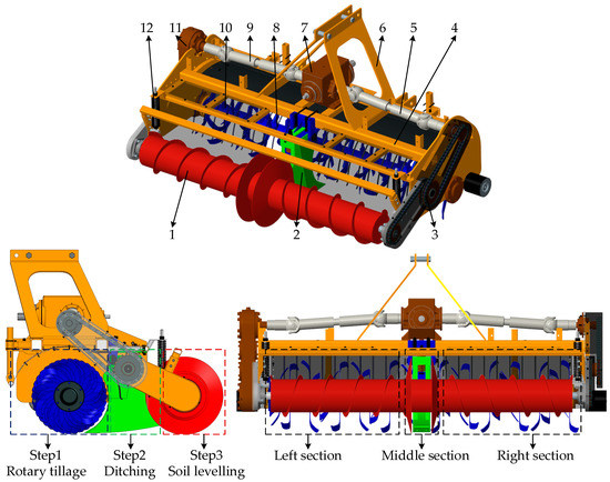
Figure 1.
Structure diagrams of seedbed preparation machine of rapeseed combined transplanter. (1) Soil leveling auger; (2) Ditch cleaning shovel; (3) Chain box; (4) Frame; (5) Right cardan joint; (6) Suspension bracket; (7) Intermediate gearbox; (8) Retaining grille; (9) Left cardan joint; (10) Rotary tillage device; (11) Side gearbox; (12) Telescopic rod.

Table 1.
Main technical parameters of seedbed preparation machine for rapeseed combined transplanter.
The seedbed preparation machine is powered by a 73.5–88.2 kW tractor and joined to the tractor using a three-point linkage system. The tractor power is distributed and transmitted through the intermediate gearbox. On the one hand, the power is transmitted to the soil leveling auger by the right cardan joint and gear drive system to realize the rotation. On the other hand, the power is transmitted to the rotary tillage device by the left cardan joint and chain drive system to drive the rotary tiller roller. The retaining grille is installed above the rotary tiller device and wrapped beyond the rotation diameter of the rotary tiller. The ditch cleaning shovel is installed between the rotary tillage device and the soil leveling auger, which is directly fixed on the frame. The rotary tillage blade roller consists of the middle section and the left–right symmetrical section. The middle section with the ditch cleaning shovel completes the ditching function, the left–right symmetrical section completes the function of rotary tillage and stubble removal. The tilling depth can be adjusted by changing the length and the angle of the pull rod. Adjusting the rotation speed of rotary tillage blade roller is realized by replacing paired gears with different speed ratios in the side gearbox.
The operation principle of the seedbed preparation machine is shown in Figure 2. In field operation, through the high-speed reversal of the rotary tiller to crush the straw, a large amount of soil and straw mixture is thrown backward. Under the action of the retaining grille, the large soil blocks and straw are obstructed and fall on the ground first. The small soil blocks passing through the retaining grille then fall to the ground under the action of the flexible curtain, forming a seedbed structure with the small soil blocks on the top and the mixture of straw and large soil blocks on the bottom. In order to ensure smooth operation and provide operation performance, the machine is separated into the middle and the left–right symmetrical section. The middle section of the rotary tillage blade breaks up the soil, the ditch cleaning shovel cuts across a ditch, and then the bevel disc in the middle section of the soil leveling auger device squeezed the soil to form a neat and smooth ditch wall. The left–right symmetrical section of the rotary tillage blade throws the soil from the middle ditch to both sides, and then the soil leveling auger device levels the soil from the middle to the sides progressively. Through the above processes, a pre-planting state of the flat and fine broken soil is formed.
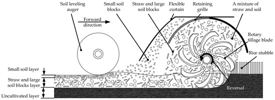
Figure 2.
Operation principle of seedbed preparation machine of rapeseed combined transplanter.
2.2. Key Component Design and Parameter Determination
2.2.1. Rotary Tillage Blade Roller Design
- Rotation direction determination
Transplanting rapeseed after rice harvest in the middle-lower Yangtze River involves dense straw cover and high moisture content soil. Therefore, a combined transplanter should minimize power consumption and retain good seedling bed conditions while ensuring rotary tillage and stubble elimination [16,17]. The positive rotary tillage first squeezes the straw into the soil, and then throws the crushed straw and soil. Therefore, the positive rotary cutting soil can generate smaller pitch and finer soil blocks. The vertical spatial distribution of straw and the coverage rate of soil surface are better than the reverse rotation. This machine adopts positive rotary tillage [18,19]. The blade roller is composed of the middle ditching section and the left–right symmetrical section, with the national standard T245 and T225 rotary tillage blades, respectively. The middle ditching section needs to cooperate with the ditch cleaning shovel operation. The middle tilling depth is 185–195 mm, and the tilling depth on both sides is 165–175 mm.
- Blade arrangement of rotary tillage section
In order to design a rotary tillage device operate with less resistance, good tillage quality, uniform force on the cutter shaft, and to avoid the occurrence of missed tillage and blockage, the arrangement of blades on the blade shaft in rotary tillage section should conform to the following principles: (1) The blades are arranged in a symmetrical spiral manner. (2) The distance between adjacent blades based on the axis is larger than the width of a single blade to reduce the missed tillage [20,21]. (3) The blades and their arrangement of the left–right rotary tillage sections must be arranged symetrically, but with cutting edges arranged in the opposite direction. Therefore, this paper chooses to analyze the arrangement of the left-handed tillage section.
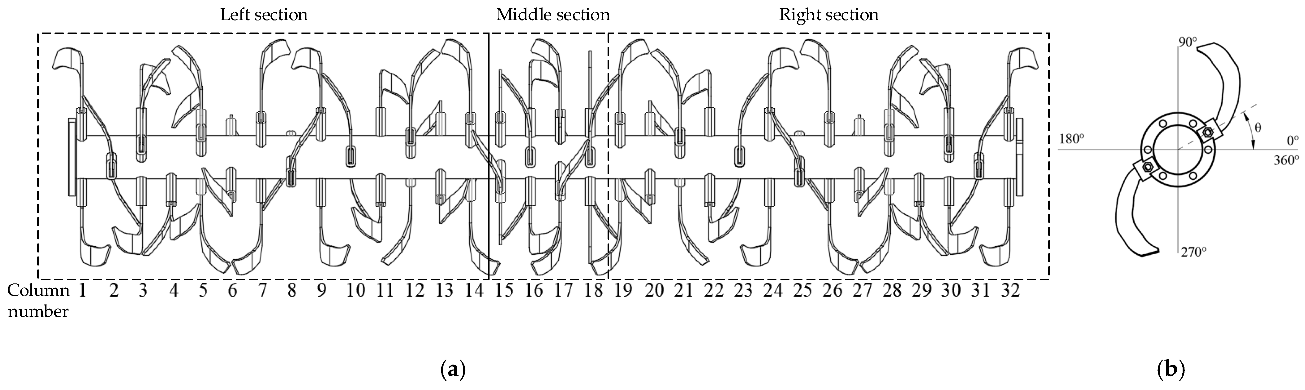
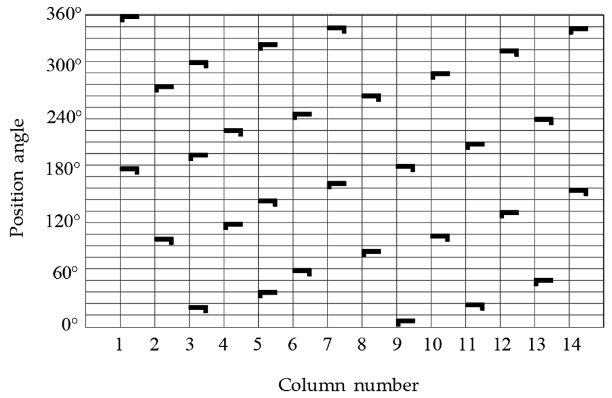
The structure diagram of a rotary tillage device is shown in Figure 3. The rotary tillage width is 2300 mm, the length of the blade shaft used to install the blade base is 200 mm, and the thickness of the blade base is 22 mm. Two adjacent rotary tillers with the same positive cutting edge on the same spiral line form a shape similar to a cylinder under the action of blade shaft rotation, so the distance between the center surfaces of the two adjacent rotary tillers cannot be too large. If the distance is too small, it is easy to clamp soil, so the distance is set to 62 mm according to the operating width of T225 rotary tillage blade with national standard [22,23]. According to the principle of smooth soil surface after tillage and no soil accumulation in the side plate clearance, the blades outside the rotary tillage section are adjusted to ensure the soil throwing uniformity. The specific blade arrangement is shown in Figure 4. The rotary tiller device is designed as 32 columns and 76 blades which are symmetrically distributed on the left and right section, each with 14 columns of blades groups, and 2–3 blades are distributed at different angles on each column. The middle section is used for ditching and has four columns of cutters.
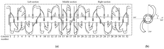
Figure 3.
Structure and position angle of rotary tillage device. (a) Structure of rotary tillage blades; (b) Diagrammatic sketch of the position angle for rotary tillage blades; (θ) Position angle of rotary tillage blades.

Figure 4.
Arrangement of rotary tillage blades for the left-handed tillage section.
- Blade arrangement of ditching section
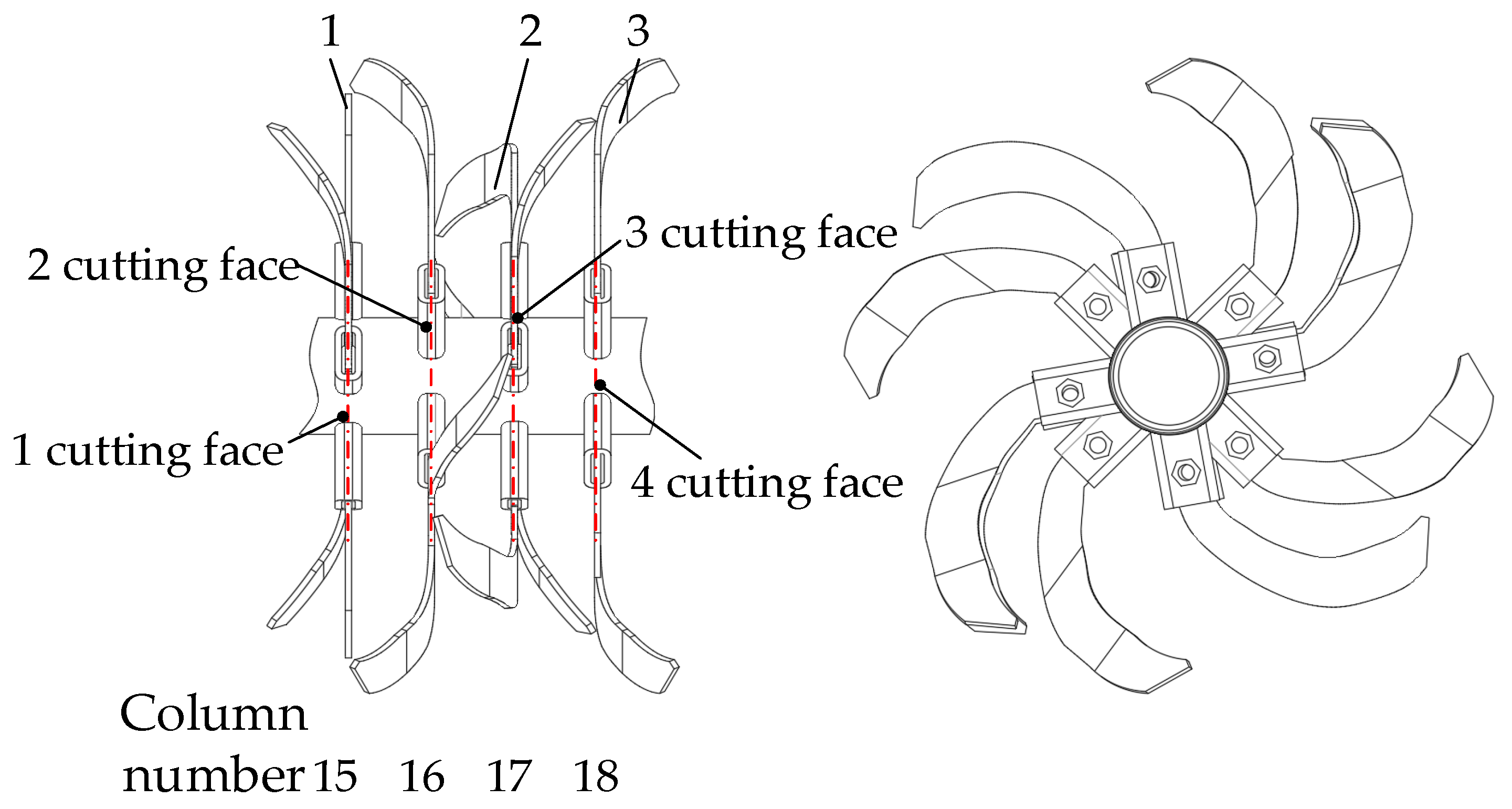
The ditching section blade arrangement is based on the requirements for ditching during transplanting of rapeseed blanket seedling—namely, a flat ditch bottom, rectangular ditch, and neat ditch surface. The middle ditching section disperses the soil to both sides of the ditch by cutting and throwing during rotary tillage, forming a ditch prototype, and then the final ditch it formed through the ditch cleaning shovel. Therefore, four longitudinal cutting surfaces are arranged in the ditching section in this paper, which are symmetrically arranged in the center face of the machine. The width of the adjacent cutting surfaces is equal, slightly larger than the width of the curved blade, which are numbered cutting surfaces 1, 2, 3, and 4. Cutting surface 1 is equipped with two left curved blades and two straight edge blades, and staggered arrangement. Cutting surface 4 is equipped with two right-curved blades and two straight edge blades, and are staggered arrangement. The straight edge blades in cutting surfaces 1 and 4 have the function of repairing the ditch wall, and cutting and throwing soil. Cutting surfaces 2 and 3 are equipped with two left-curved blades and two straight edge blades respectively, and are set in a staggered arrangement. Cutting surfaces 2 and 3 stagger at a 45° angle to ensure that every 45° angle has a blade into the soil, while ensuring that the left- and right-curved blades alternately into the soil, which is conducive to the stability and balance of the blade shaft force. The middle ditching section structure is shown in Figure 5.
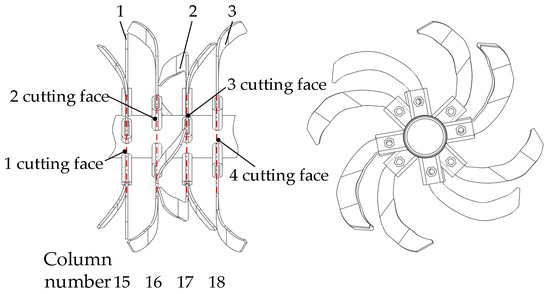
Figure 5.
Structure diagrams of middle ditching section. (1) Left-curved blade; (2) Right-curved blade; (3) Straight blade.
2.2.2. Structure and Parameter Design of Ditch Cleaning Shovel
- Structure design of ditch cleaning shovel
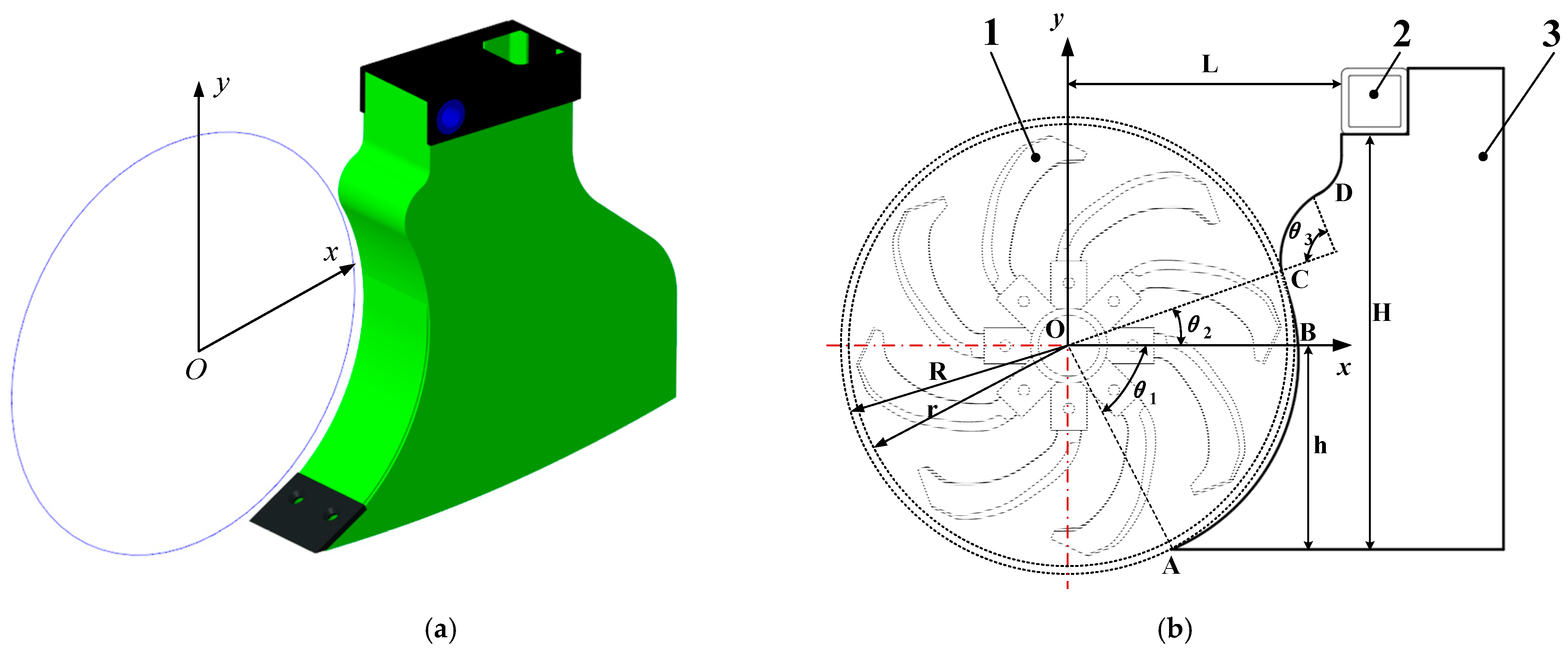
The structure curve of envelope ditch cleaning shovel is shown in Figure 6, which is composed of the soil contact section AB, the soil throwing section BC, the transition section CD, and the installation fixed section. When working, the sections where the ditch cleaning shovel contacts with the soil and is wrapped in grass are the AB and BC. In order to realize the function that the rotary tillage blade actively scrapes the mixture of soil and straw adhering to the fertilizer shovel, the AB and BC sections were designed to be concentric with the rotary center of the rotary tillage blade shaft and to have circular arcs with the same diameter as the end trajectory of the envelope rotary blade. The comprehensive ditch depth of AB section should be determined by the rotary radius of rotary blade. The larger the central angle of the arc in the BC section, the better the enveloping effect of the ditch cleaning shovel, and the lesser the amount of adhering soil and enlacing straw. However, if the center angle is too large, it is easy to cause shovel handle foreraking and structural strength reduction [24].

Figure 6.
Structure curve of envelope ditch cleaning shovel. (a) Structural diagrams of ditch cleaning shovel; (b) Curve of envelope ditch cleaning shovel; (1) Rotary tillage blades; (2) Frame; (3) Ditch cleaning shovel; (O) Rotary center of rotary axis; (AB) Entry section curve of ditch cleaning shovel; (BC) Throwing section curve of ditch cleaning shovel; (CD) Transition section curve of ditch cleaning shovel; (r) Rotary radius of rotary blade; (R) Radius of envelope curve for ditch cleaning shovel; (θ1) Angle of entry section; (θ2) Angle of throwing section; (θ3) Angle of transition section; (h) Vertical distance from the lowest point of ditch cleaning shovel to rotary center; (H) Vertical distance from the lowest point of ditch cleaning shovel to the bottom of fixed beam; (L) Vertical distance from the front side of fixed beam to rotary center.
- Parameter design of arc radius
In order to cooperate the curved surface of the soil contact arc of the ditch cleaning shovel with the rotary tillage blade, and to enable the rotary tillage blade to actively scrape the mixture of soil and straw adhering to the ditch cleaning shovel, the arc center of the ditch cleaning shovel entry section is designed to coincide with the rotation center of the rotary tillage blade shaft, and the envelope radius is designed to be slightly larger than the rotary radius of the rotary tillage blade shaft. Considering the cooperation between the ditch cleaning shovel and the rotary blade, the gap Δδ between the blade end section and the working surface should be as small as possible to avoid interference [25].
Moreover, the limit value of the center distance deviation of the blade handle fixed hole is provided as 2.0 mm. Δδ is determined as 5 mm according to the previous test. The enveloping radius of the arc section of the ditch cleaning shovel is determined as R = Δδ + r, where r is the rotation radius of rotary tillage blade.
- Parameter design of arc central angle of soil entry section
The main working surface of the ditch cleaning shovel is the AB surface in the soil entry section, and the working parameters determine the ditching depth. As shown in Figure 4, according to the difference value between the ditching depth and the rotary tillage depth, the distance between point A of the ditching shovel and the rotary center of the rotary tillage blade is determined as h, which is smaller than the envelope radius of arc in soil contact section [25].
In this paper, h is determined as 240 mm. θ1 is calculated as 73.74°.
- Parameter design of arc central angle of soil throwing section
The BC surface in throwing soil section affects the throwing performance. An excessively small arc center angle(θ2) in throwing soil section will cause the soil thrown behind the rotary tiller to adhere to the shovel, resulting in the blockage of the machine. An excessive arc center angle(θ2) will result in long movement trajectory of soil thrown with the rotary tiller blade, thereby increasing energy consumption and reducing machine passing rate [25].
Considering the installation position and structural space of the frame, the value of θ2 is determined as 26°.
2.2.3. Structure and Parameter Design of Soil Leveling Auger
- Structure design of soil leveling auger
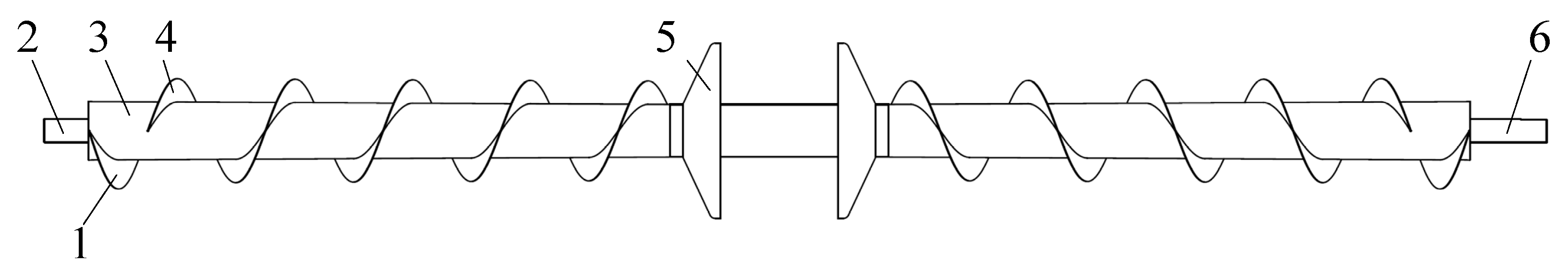
After the preliminary rotary tillage and ditching operation, the soil in the middle ditch section is thrown to both sides of the ditch. Although the preliminary leveling of field surface is achieved by optimizing the arrangement of rotary tillage blades, it still can not satisfy the requirements of soil levelness. Therefore, a leveling auger device with a variable diameter structure is designed to realize the function that soil is gradually transported to both sides of the ditch. Meanwhile, considering the thrust effect of the soil on the forward direction of the machine, some soil is transported or squeezed to the end of the auger, resulting in blockage and an uneven field surface. Therefore, the anti-rotating blades are designed at the end of the auger so as to continuously transport the soil accumulated at the end to the middle of the ditch [26]. The specific structure is shown in Figure 7.
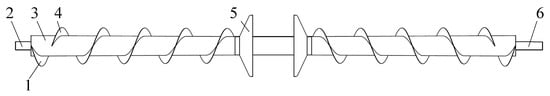
Figure 7.
Structure diagram of soil leveling auger. (1) Reverse blade; (2) Power drive shaft; (3) Auger shaft; (4) Conveying blade; (5) Conical disc; (6) Chain drive shaft.
- Parameter design of conveying value
The conveying capacity of the soil leveling auger is related to the structure parameters of the middle ditch, soil bulk density, and machine forward speed. During the working process of the soil leveling auger, the sectional area of the auger shaft has a certain influence on the conveying capacity. Therefore, the soil conveying capacity of the soil leveling auger is calculated according to the following equation [27].
where Q denotes the conveying capacity of soil leveling auger, t/h; s denotes the sectional area of the middle ditch, which is designed as 0.036 m2; vm denotes machine forward speed, which is determined as 1.0 m/s; ρ denotes soil bulk density, which is determined as 1.26 t/m3; ε denotes the conveying coefficient, which is related to the arrangement of the auger determined as 0.3.
- Parameter design of spiral blade diameter
The equation for the diameter of the helical blade is as follows, which is determined according to the production capacity of auger device, type of conveying material, structure, and arrangement [27].
where D0 denotes the diameter of the helical blade, m; K denotes material comprehensive coefficient, which is determined as 0.05; C denotes the inclination angle coefficient, which is determined as 1 due to that the soil leveling auger is horizontal placement; ψ denotes the proportion of soil in the spiral cross section, which is determined as 0.75.
Substituting the above data into Equation (2), the calculated result is that D0 ≥ 0.184 m. The diameter of the helical blade(D0) needs to take the standard value, such as 100, 120, 150, 200, 250, 300, 400, 500, and 600 mm. Therefore, the value of D0 is rounded and set to 200 mm.
- Parameter design of thread pitch
Thread pitch not only determines the helix angle of spiral surface, but also determines the sliding surface of the soil movement. Therefore, the thread pitch directly affects the soil conveying process and the smoothness of the soil leveling auger, which can be calculated as follows [28].
where S denotes thread pitch, m.
For the standard spiral device, K1 = (0.8–1.0). When the spiral device is installed obliquely or the flowability of conveying materials is poor, K1 ≤ 0.8. Due to the poor flowability of clay, K1 is determined as 0.6. The calculated result is that S = 120 mm.
- Parameter design of the diameter of the auger shaft
The diameter of the auger shaft is related to thread pitch. Both of them determine the helix angle of spiral blade, slip direction, and velocity distribution of the soil. Usually in the case of ensuring that the soil leveling auger is not covered with soil and satisfies the structural strength, the device structure is as compact as possible. The equation of the diameter of the auger shaft is as follows [27].
where x denotes auger shaft coefficient, which is in the range of 0.2–0.35 and determined as 0.25.
The calculated diameter of auger shaft (d) is 50 mm.
2.3. Parameters Optimization Test of Seedbed Preparation Machine
2.3.1. Test Condition
The tests were carried out in the test base of Baima Town, China in November 2020. The characteristic parameters of soil were determined before the test. The soil volume density in the depth of 0–10 cm is 1.32 g/cm3, and 10–20 cm is 1.64 g/cm3. The soil moisture content in the depth of 0–5 cm is 24.3%, 5–10 cm is 28.7%, 10–15 cm is 31.2%, and 15–20 cm is 33.8%. The test site is shown in Figure 8.
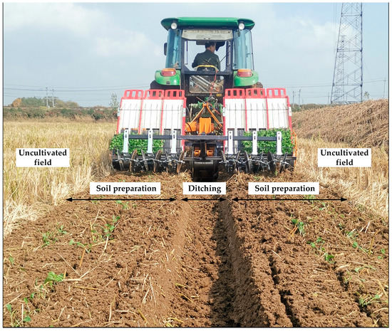
Figure 8.
Test equipment and site.
The equipment comprised of John Deere 1206 tractor, SC-900 soil compaction meter, MS-350 moisture meter, electronic balance, electronic scale, and steel ruler.
2.3.2. Test Method
The test indicators were selected as the soil breaking rate, straw coverage rate, and soil flatness. The total length of the test area was 30 m, from which 20 m was taken as the stable measurement area. A group of tests under the same conditions were repeated three times, and the results were averaged.
- Soil breaking rate
The sample area of 0.5 × 0.5 m is selected, and in the whole tillage layer, the mass percentage of the soil block whose longest side is less than 4 cm to the total soil is defined as the soil breaking rate. The formula is
where Y1 denotes soil breaking rate, %; ma denotes the mass of the soil blocks with the longest side length less than 4 cm in the total tillage layer, kg; mb denotes all soil mass in the total tillage layer, kg.
- Straw coverage rate
A measure area of 1 × 1 m is randomly selected from each group of tests, and the formula of the straw coverage rate is
where Y2 denotes straw coverage rate, %; Mq denotes straw quality per unit area before tillage, g/m2; Mh denotes unburied straw mass per unit area after tillage, g/m2.
- Soil flatness
The soil flatness reference height was measured before the test, which was 21 mm. The stable measurement area is divided into 10 routes, and 5 measurement points are selected in each route. The height of the ground surface before and after the operation was measured, and the formula of soil flatness is
where Y3 denotes soil flatness, mm; aj denotes the ground height with the route j, mm; aji denotes the ground height with the route j and the measuring point i, mm; ni denotes the number of the measuring points; nj denotes the number of the measuring points in the route j.
2.3.3. Test Factor
The purpose of the field test is to find the most suitable operating parameters of the seedbed preparation machine and to explore the influence rules of various factors on the soil tillage performance before the rapeseed combined transplanting. A series of Box–Behenken response surface tests at three factors and three levels was conducted to evaluate soil breaking rate (Y1), straw coverage rate (Y2) and soil flatness (Y3). Under the condition that the arrangement of the rotary tillage blades, structural parameters of ditch cleaning shovel, and soil leveling auger have been determined, the forward speed (X1), rotation speed of rotary tillage blade roller (X2), and the rotation speed of soil leveling auger (X3) were selected as the test factors. Each factor took three levels, with the following defining rules. In order to ensure the soil broken performance and planting quality, the forward speed was 0.8–1.4 m/s, and the range of the factor was divided into three levels—namely 0.8, 1.1, and 1.4 m/s. Due to the centrifugal force and Coriolis force caused by the rotation and revolution, the soil may be thrown along the circumference of the screw shaft. Considering the soil stickiness in the rice–rapeseed rotation area in the middle and lower reaches of the Yangtze River in China, the requirement of broken soil quality was high. Combined with a GB/T 5668-2008 “Rotary Tiller”, the rotation speed of rotary tillage blade roller was obtained in the range of 250–350 r/min, evenly divided in three levels—namely 250, 300, and 350 rpm. Considering the self-transmission speed of the soil leveling auger shaft formed by the forward speed, the range of the rotation speed of the soil leveling auger was selected to be 180–240 rpm, evenly divided in three levels—namely 180, 210, and 240 rpm. In summary, the factors and their levels are presented in Table 2.
Table 2.
Three factors and three levels of parameter optimization test for seedbed preparation machine.
3. Results
The parameter optimization test scheme of the seedbed preparation machine was designed according to the Box–Behenken response surface tests with three factors and three levels. The specific test scheme and the obtained test data results are shown in Table 3.
Table 3.
Test scheme and result of parameter optimization test for seedbed preparation machine.
The test results obtained in Table 3 were data-analyzed by Design Expert software 8.0, mainly including regression equation construction, ANOVA, response surface map drawing, influence factor interaction analysis, and optimal parameter combination solution.
3.1. Regression Equation Construction
Firstly, according to the test data, the regression equation—as shown in Equation (8)—between three test indicators and three test factors was established by using multiple regression method.
where Y1 denotes soil breaking rate, %; Y2 denotes straw coverage rate, mm; Y3 denotes soil flatness, mm; X1 denotes forward speed, m·s−1; X2 denotes rotation speed of rotary tillage blade roller, rpm; X3 denotes rotation speed of soil leveling auger, rpm.
3.2. Variance Analysis
The ANOVA and the regression coefficient significance checkout were performed on the secondary regression models, and the ANOVA results of the test indicators are listed in Table 4, Table 5 and Table 6.
Table 4.
Variance analysis results of seedbed preparation machine parameter optimization test for soil breaking rate.
Table 5.
Variance analysis results of seedbed preparation machine parameter optimization test for straw coverage rate.
Table 6.
Variance analysis results for soil flatness of seedbed preparation machine parameter optimization test.
The results of the ANOVA showed that the test model was statistically significant (p < 0.05). The variance analysis of soil breakage rate in Table 4 shows that X2 had the most significant influence on the index in the primary item. The interaction terms X1X2 on the soil breaking rate was statistically significant (p < 0.05). The primary and secondary relationship of three parameters on soil breakage rate was X2 > X3 > X1. The variance analysis of straw coverage rate in Table 5 shows that the effect of the primary items X1 and X2 on the straw coverage rate was statistically significant (p < 0.05). Furthermore, the primary and secondary relationship of three parameters on this index was X2 > X1 > X3. The variance analysis of soil flatness in Table 6 shows that the primary and secondary relationship of three parameters on this index was X3 > X2 > X1.
Moreover, the interaction term X1X2, X2X3 has a relative significant influence on the soil breaking rate and straw coverage rate respectively. The significant influence of the interaction term X1X3 and X2X3 on soil flatness were high and similar. Therefore, the response surface analysis of these interaction items was carried out. Figure 7 shows the response of surfaces of soil breaking rate to interactive factors X1X2. Figure 8 shows the response of surfaces of straw coverage rate to interactive factors X2X3. Figure 9 shows the response of surfaces of soil flatness to interactive factors X1X3 and X2X3.
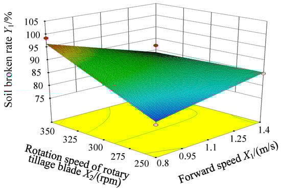
Figure 9.
Response surfaces of soil breaking rate to interactive factors X1X2.
3.3. Response Surface Analysis of Interaction Items
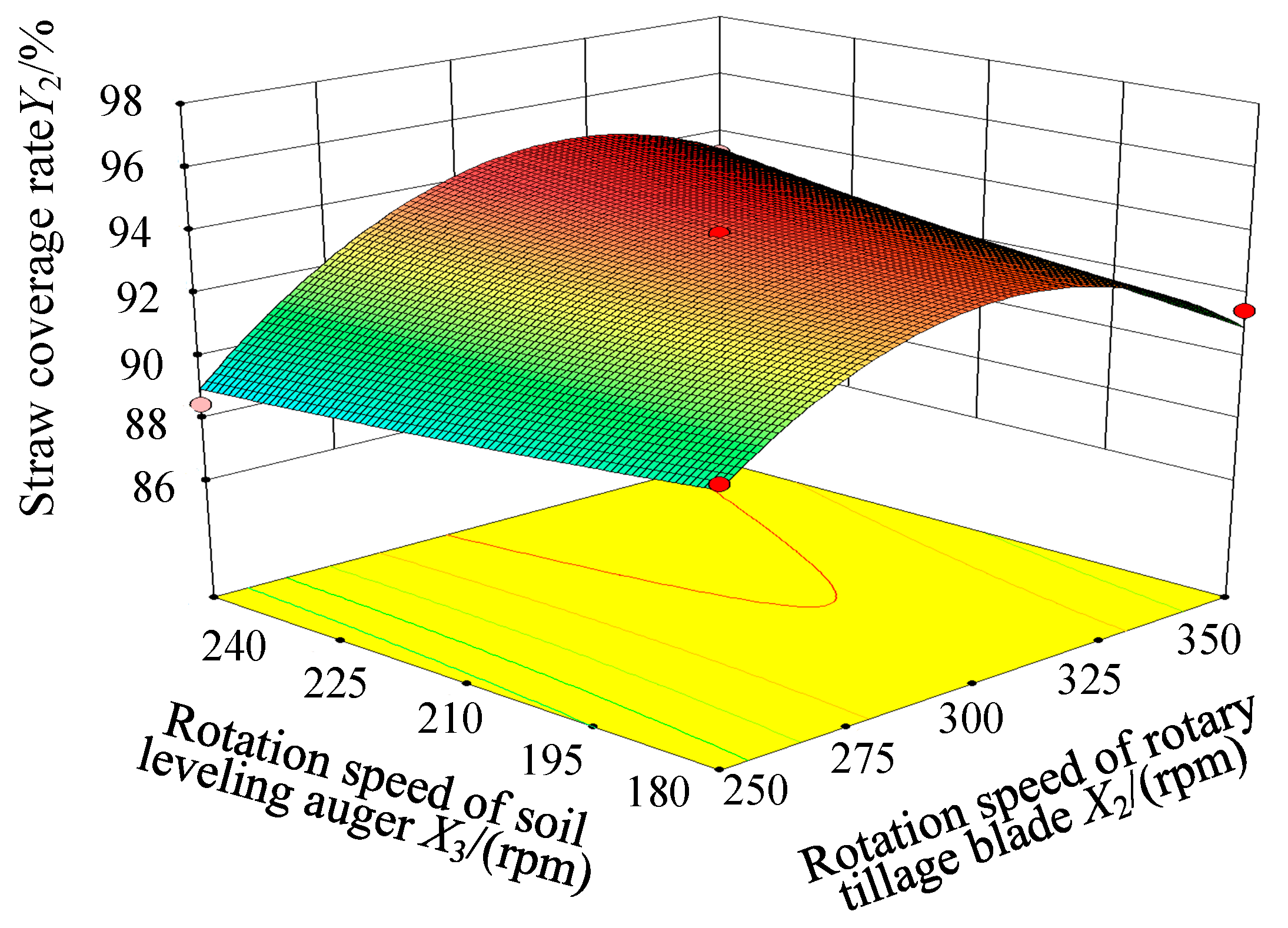
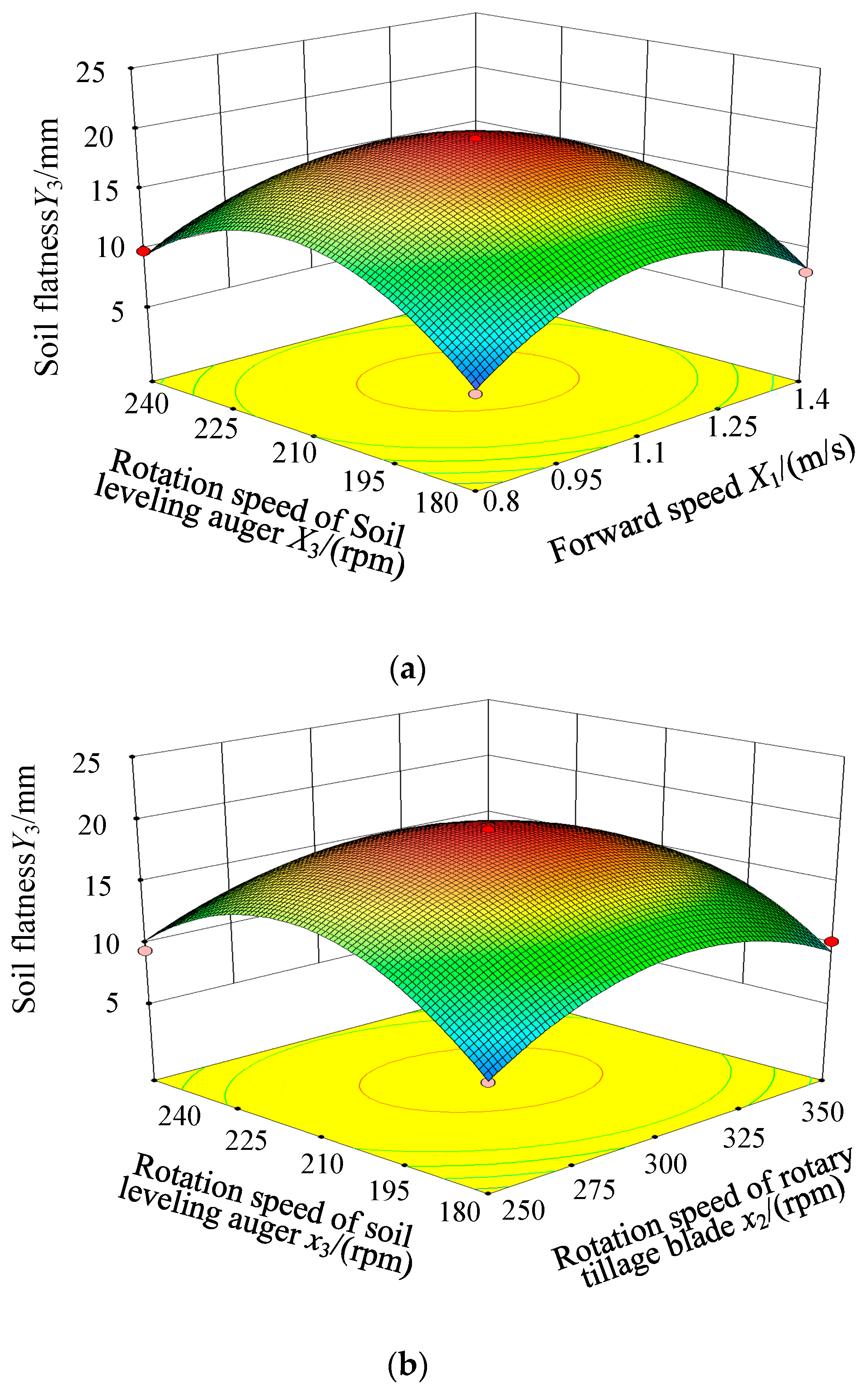
As shown in Figure 9, the soil breaking rate increased with the increase in the forward speed and the rotation speed of rotary tillage blade roller. As shown in Figure 8, the straw coverage rate initially increased, and subsequently decreased with the increase in the rotation speed of rotary tillage blade roller. When the rotation speed of the rotary tillage blade roller was 308 rpm, the straw coverage rate was the largest. Since the rotation speed of rotary tillage blade roller had a great influence on the power consumption of the machine, the rotation speed of the rotary tillage blade roller should be as low as possible under the premise of satisfying the soil breaking rate and straw coverage rate. As shown in Figure 10, the straw coverage rate slightly decreased with the increase in the rotation speed of soil leveling auger, which was mainly due to the fact that the straw coverage had been completed in the rotary tillage process, the mixed layer with the soil and straw was disturbed, and the covered straw was turned out by the screw blade of the soil leveling auger. As shown in Figure 11a,b, the soil flatness initially increased, and subsequently decreased with the increase in the forward speed, the rotation speed of rotary tillage blade roller, and the rotation speed of soil leveling auger. When the forward speed was 1.04 m/s, the rotation speed of rotary tillage blade roller was 287 rpm, and the rotation speed of the soil leveling auger was 217 rpm, the soil flatness was the most reasonable.
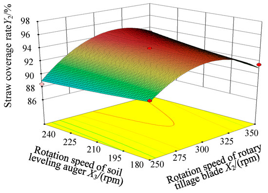
Figure 10.
Response surfaces of straw coverage rate to interactive factors X2X3.
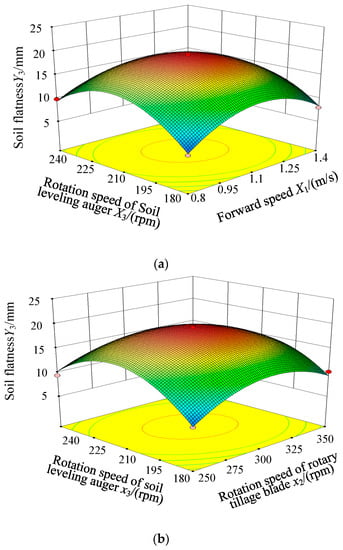
Figure 11.
Response surfaces of soil flatness to interactive factors X1X3 and X2X3. (a) Forward speed and rotation speed of leveling auger effect on soil flatness; (b) Rotation speed of rotary tillage blade and rotation speed of soil leveling auger effect on soil flatness.
In order to obtain the optimal working parameters of the seedbed preparation machine before transplanting of rapeseed combined transplanter, the optimization module in the Design Expert 8.0.6 software was used to optimize the constraint targets of the above three regression models. According to the actual operation and related theories, the optimization constraints, objectives, and constraint functions were selected, and the results were obtained as follows: when the forward speed was 0.94, the rotation speed of rotary tillage blade roller was 268 rpm, and the rotation speed of soil leveling auger was 204 rpm, the optimized results obtained were a soil breaking rate of 92.27%, straw coverage rate of 93.68%, and soil flatness of 8.85 mm.
3.4. Test Verification
A verification test was carried out to verify the optimal parameter combination obtained by the parameter optimization test result analysis. The test conditions were the same as the previous ones, guaranteeing similar soil condition parameters to the previous parameter optimization test. The verification test was also carried out in the test base of Baima Town, China, in January 2021. According to the results of parameter optimization, each factor of the verification tests was set as follows: the forward speed was 0.94 m·s−1, the rotation speed of rotary tillage blade roller was 268 rpm, and the rotation speed of soil leveling auger was 204 rpm. The test was repeated three times for each group. After that, the test results were averaged and shown in Table 7.
Table 7.
Verification test results of seedbed preparation machine.
The test results showed that—under the optimal working parameters solved by the software—the average soil breaking rate was 92.06%, the straw coverage rate was 93.01%, and the soil flatness was 8.35 mm. The errors in the regression model were 0.23%, 0.72%, and 5.65%, respectively, which were all controlled within the 10% range, indicating the accuracy of the parameter optimization test model. Thus, the test result showed that the calculated accuracy of the regression model of soil breaking rate, straw coverage rate, and soil flatness could satisfy the requirements of machine performance.
4. Conclusions
Aiming at the problems of high soil agglomeration and poor flatness in the soil preparation process of the rapeseed blanket seedling combined transplanter, a seedbed preparation machine with functions of rotary tillage and stubble ploughing, ditching, and soil leveling was designed. The rotary tillage blades, ditch cleaning shovel, soil homogenizing auger, and other key components were designed.
In order to further improve the working performance of the seedbed preparation machine, the working process of the rotary tillage device and the soil leveling auger device was analyzed. Taking the forward speed in the range of 0.8–1.4 m/s, rotation speed of rotary tillage blade roller in the range of 250–350 r/min, and rotation speed of soil leveling auger in the range of 180–240 rpm as the influencing factors on the soil breaking rate, straw coverage rate, and soil flatness as the performance index, a three-factors and three-levels response surface test was carried out. The regular influence of the seedbed preparation machine on soil tillage performance was proved, the regression model of the test index was obtained. Finally, the optimal parameter combination was obtained as follows: when the forward speed was 0.94 m/s, the rotation speed of rotary tillage blade roller was 268 rpm, and the rotation speed of soil leveling auger was 204 rpm. The optimization result calculated by the model was that the soil breaking rate was 92.27%, the straw coverage rate was 93.68%, and the soil flatness was 8.85 mm.
In order to verify the accuracy of the model optimization results, the field verification test was carried out, and the test data showed that under the optimal working parameters calculated by the regression model, the soil breaking rate was 92.06%, the straw coverage rate was 93.01%, and the soil flatness was 8.35 mm. The errors with the regression model predicted values were 0.23%, 0.72%, and 5.65%, respectively, which showed that the calculated accuracy of the regression model of soil breaking rate, straw coverage rate, and soil flatness could satisfy the performance requirements of a seedbed preparation machine for a rapeseed combined transplanter.
5. Discussion
The field test proves that the soil breaking rate, straw coverage rate, and soil flatness of the seedbed preparation machine designed in this paper all satisfied the agronomic requirements, creating a seedbed environment suitable for the transplanting of rapeseed blanket seedling. The planting mode of rapeseed transplanting is mainly applicable in China, and other countries are mainly based on direct seeding, consequently there is no relevant research. The cultivation of rapeseed in China is mainly concentrated in the rice-oil rotation area of the Yangtze River Basin. In this area, the soil has a high moisture content and the transplanting equipment is ineffective, which seriously limits the development of mechanized rapeseed transplanting. Before 2011, the level of mechanized rapeseedling transplanting in China was almost zero. Rapeseed blanket transplanting was created in this urgent environment, and it is a new planting method suitable for Chinese agricultural conditions. In order to further develop rapeseed blanket seedling transplanting technology, it is particularly important to create standardized and unified seedbed conditions through soil preparation before transplanting. At present, there are few studies on soil preparation technology before transplanting rapeseed blanket seedlings.
However, some scholars have researched a lot of work on combined tillage equipment. Developed countries such as Europe and the U.S. began to develop and promote combined tillage machinery in the 1960s, such as the Case 730C combined soil preparation machine and the John Deere 2730 combined soil preparation machine. In response to the main domestic demand for small fields, China has reduced the tilling width, and designed combined tillage machines including the soil preparation method of subsoiling + rotary tillage, mouldboard plow + rotary tillage, subsoiling + stubble + suppression, etc. The team of Wang Jinwu from Northeast Agricultural University proposed the rice straw deep buried and whole straw returning technology [29]. This machine only needs to once pass of soil to complete the deep burial and returning of rice straw, which constitutes high performance. The soil flatness and soil breaking rate of the designed machine are both greater than 90%, which provides a reference for our design. Qin Kuan et al. [30] designed a compound operation machine, combining a plough and rotary tiller. The straw burial rate exceeds 90%, and both the operation efficiency and quality of this machine are better than single ploughing and single rotary tillage.
In addition to optimizing the performance parameters of machines through field tests, some scholars use the discrete element method for research [31,32]. In the next step, the device will be tested with the discrete element method to analyze the interaction regular between the devices in each process and between the device and the soil, analyzing the distribution regular between the soil and straw under the operation of the device so as to further optimize the design of the seedbed preparation machine.
Author Contributions
Conceptualization, J.W.; Methodology, L.J. and J.W.; Software, Q.T.; Validation, L.J.; Formal analysis, J.W. and Q.T.; Investigation, W.Y.; Resources, D.J.; Data curation, J.W.; Writing—original draft preparation, L.J.; Writing—review and editing, L.J.; Visualization, D.W. and M.Z.; Supervision, W.Y.; Project administration, J.W.; Funding acquisition, J.W. and M.Z. All authors have read and agreed to the published version of the manuscript.
Funding
This research was funded by Key Research and Development Program of Jiangxi Province (20212BBF63039), and Key Research and Development Program of Jiujiang City (S2021ZDYFN069), and Modern Agricultural Industry Technology System Construction of China (CARS-12), and Central Public-interest Scientific Institution Basal Research Fund (NO. Y2022XC07), and Key Research and Development Program of Jiangsu Province (BE2020317).
Institutional Review Board Statement
Not applicable.
Data Availability Statement
The data presented in this study are available on request from the authors.
Acknowledgments
The authors thank the editor and anonymous reviewers for providing helpful suggestions for improving the quality of this manuscript.
Conflicts of Interest
The authors declare no conflict of interest.
References
- Wu, J.; Tang, Q.; Yuan, W.; Wang, S.; Wu, C. Design and parameter optimization of ditching and compacting parts of rapeseed carpet seedling transplanter. Trans. Chin. Soc. Agric. Eng. 2016, 32, 46–53. [Google Scholar]
- Jiang, L.; Wu, C.; Tang, Q.; Zhang, M.; Wang, G. Kinematics model and parameter optimization of planting process of rape carpet seedling transplanter. Trans. Chin. Soc. Agric. Eng. 2018, 34, 37–46. [Google Scholar]
- Tang, Q.; Wu, C.; Wu, J.; Qin, C.; Jiang, L.; Wang, G. Electro-hydraulic proportional control system of hole distance for rape seedling rotary tillage combined transplanter. Trans. Chin. Soc. Agric. Mach. 2020, 51, 61–68. [Google Scholar]
- Luo, H.; Guan, C.; Tang, C.; Chen, S.; Xie, F.; Wu, M. Ditching parts of no-tillage sower in paddy stubble field. Trans. Chin. Soc. Agric. Eng. 2007, 23, 153–157. [Google Scholar]
- Xiao, M.; Xiao, S.; Chen, B.; Sun, S.; Xiong, L. Design and Experiment of Horizontal Push Seedling Transplanting Mechanism for Rapeseed Seedling Opening Groove. Trans. Chin. Soc. Agric. Mach. 2019, 50, 56–63, 71. [Google Scholar]
- Liu, M.; Hu, X.; Liao, Y.; Liao, Q.; Wan, X.; Ji, M. Morphological parameters characteristics of mechanically transplanted plant in suitable transplanting period for different rape varieties. Trans. Chin. Soc. Agric. Eng. 2015, 31, 79–88. [Google Scholar]
- Jin, X.; Li, D.; Ma, H. Development of single row automatic transplanting device for potted vegetable seedlings. Int. J. Agric. Biol. Eng. 2018, 11, 67–75. [Google Scholar] [CrossRef]
- Wang, Y.; He, Z.; Wang, J. Experiment on transplanting performance of automatic vegetable pot seedling transplanter for dry land. Trans. Chin. Soc. Agric. Eng. 2018, 34, 19–25. [Google Scholar]
- Wu, C.; Wu, J.; Zhang, M. Research on machine transplanting techniques of blanket rapeseed. J. Chin. Agric. Mech. 2016, 37, 6–10. [Google Scholar]
- Shahgoli, G.; Fielke, J.; Desbiolles, J. Optimising oscillation frequency in oscillatory tillage. Soil Tillage Res. 2010, 106, 202–210. [Google Scholar] [CrossRef]
- Prasanna Kumar, G.; Raheman, H. Development of a walk-behind type hand tractor powered vegetable transplanter for paper pot seedlings. Biosyst. Eng. 2011, 110, 189–197. [Google Scholar] [CrossRef]
- Zhao, J.; Wang, A.; Ma, Y.; Li, J.; Hao, J.; Nie, Q.; Long, S.; Yang, Q. Design and test of soil preparation machine combined subsoiling, rotary tillage and soil breaking. Trans. Chin. Soc. Agric. Eng. 2019, 35, 46–54. [Google Scholar]
- Zhao, D.; Li, L.; Xu, C.; Zhang, C.; Li, X.; Li, M. 1ZQHF-350 /5 Hang Combined Cultivating Machine with Front-stubble-breaking, Post-subsoil and Rotary-tilling Equipment. Trans. Chin. Soc. Agric. Mach. 2014, 45, 92–96. [Google Scholar]
- Zhang, X.; Li, L.; Wang, C.; Zhao, D. Design and test of 1GSZ-350 stubble-breaking and rotary tilling combined cultivating machine. Trans. Chin. Soc. Agric. Eng. 2009, 25, 73–77. [Google Scholar]
- Wang, X.; Huang, Y.; Qin, Z.; Li, Y. Theoretical and experimental research on 1LZ-5.4 tillage combine. Trans. Chin. Soc. Agric. Mach. 1996, 27, 19–22. [Google Scholar]
- Liu, X.; Xiao, W.; Ma, L.; Liu, L.; Wan, G.; Liao, Q. Design and Ditching Quality Experiment on Combined Ship Type Opener of Direct Rapeseed Seeder. Trans. Chin. Soc. Agric. Mach. 2017, 48, 79–87. [Google Scholar]
- Yan, W.; Hu, M.; Li, K.; Wang, J.; Zhang, W. Design and Experiment of Horizontal Transplanter for Sweet Potato Seedlings. Agriculture 2022, 12, 675. [Google Scholar] [CrossRef]
- Guo, J.; Ji, C.; Fang, H.; Zhang, Q.; Hua, F.; Zhang, C. Experimental Analysis of Soil and Straw Displacement after Up-cut and Down-cut Rotary Tillage. Trans. Chin. Soc. Agric. Mach. 2016, 47, 21–26. [Google Scholar]
- Xu, G.; Xie, Y.; Liang, L.; Ding, Q.; Xie, H.; Wang, J. Straw-Soil-Rotary Blade Interaction: Interactive Effects of Multiple Operation Parameters on the Straw Movement. Agronomy 2022, 12, 847. [Google Scholar] [CrossRef]
- Han, L.; Yuan, W.; Yu, J.; Jin, J.; Xie, D.; Xi, X.; Zhang, Y.; Zhang, R. Simulation and Experiment of Spiral Soil Separation Mechanism of Compound Planter Based on Discrete Element Method (DEM). Agriculture 2022, 12, 511. [Google Scholar] [CrossRef]
- Jia, H.; Cheng, Z.; Guo, H.; Li, R.; Li, X. Study on working principle of rotary tillage and stubble cutting and design of universal knife roller. Trans. Chin. Soc. Agric. Mach. 2000, 4, 29–32. [Google Scholar]
- Li, Z.; Xu, K.; Yan, S.; Xu, L.; Yang, Y.; Wang, Z. Structural Design and test of stubble cutter roller for two-axis rotary stubble mitigation machine. J. Agric. Mech. Res. 2020, 42, 117–124+131. [Google Scholar]
- Zhang, C.; Xia, J.; Zhang, J.; Zhou, H.; Zhu, Y.; Wang, J. Design and Experiment of Knife Roller for Six-head Spiral Straw Returning Cultivator. Trans. Chin. Soc. Agric. Mach. 2019, 50, 25–34. [Google Scholar]
- Liao, Y.; Gao, L.; Liao, Q.; Zhang, Q.; Liu, L.; Fu, Y. Design and Test of Side Deep Fertilizing Device of Combined Precision Rapeseed Seeder. Trans. Chin. Soc. Agric. Mach. 2020, 51, 65–75. [Google Scholar]
- Sineakov. Theory and Calculation of Soil Tillage Machinery; China Agricultural Machinery Press: Beijing, China, 1981. [Google Scholar]
- Zhang, X.; Liu, Y.; Li, L.; Tong, Z.; Yang, D.; Hou, C. Design and performance experiment of multi-segment type auger in process of organic fertilizer production. Trans. Chin. Soc. Agric. Eng. 2018, 34, 49–56. [Google Scholar]
- Huang, X. Transportation Machinery Selection and Design Manual, 2nd ed.; Chemical Industry Press: Beijing, China, 2011. [Google Scholar]
- Luo, S.; Zhang, X.; Xu, J.; Ma, K. Structure optimization and performance simulation of screw discontinuous feeding device. Trans. Chin. Soc. Agric. Eng. 2013, 29, 250–257. [Google Scholar]
- Wang, J.; Chen, B.; Jiang, Y.; Zhu, M.; Xia, J.; Wang, J. Design and Experiment on Machine for Rice Straw Full Quantity Deep Buried into Field. Trans. Chin. Soc. Agric. Mach. 2020, 51, 84–93. [Google Scholar]
- Qing, K.; Ding, W.; Fang, Z.; Du, T.; Zhao, S.; Wang, Z. Design and experiment of plowing and rotary tillage combined machine. Trans. Chin. Soc. Agric. Eng. 2016, 32, 7–16. [Google Scholar]
- He, R.; Duan, Q.; Chen, X.; Xu, G.; Ding, Q. DEM Analysis of Spatial Distribution Quality of Rotary Tillage Straw Returning. Trans. Chin. Soc. Agric. Mach. 2022, 53, 44–53. [Google Scholar]
- Mari, I.; Chandio, F.; Ji, C. Performance and evaluation of disc tillage tool forces acting on straw incorporation soil. Pak. J. Agric. Sci. 2014, 51, 855–860. [Google Scholar]


Publisher’s Note: MDPI stays neutral with regard to jurisdictional claims in published maps and institutional affiliations. |
© 2022 by the authors. Licensee MDPI, Basel, Switzerland. This article is an open access article distributed under the terms and conditions of the Creative Commons Attribution (CC BY) license (https://creativecommons.org/licenses/by/4.0/).