
Design and Testing of an Elastic Comb Reciprocating a Soybean Plant-to-Plant Seedling Avoidance and Weeding Device


 and
and
Abstract
:1. Introduction
2. Materials and Methods
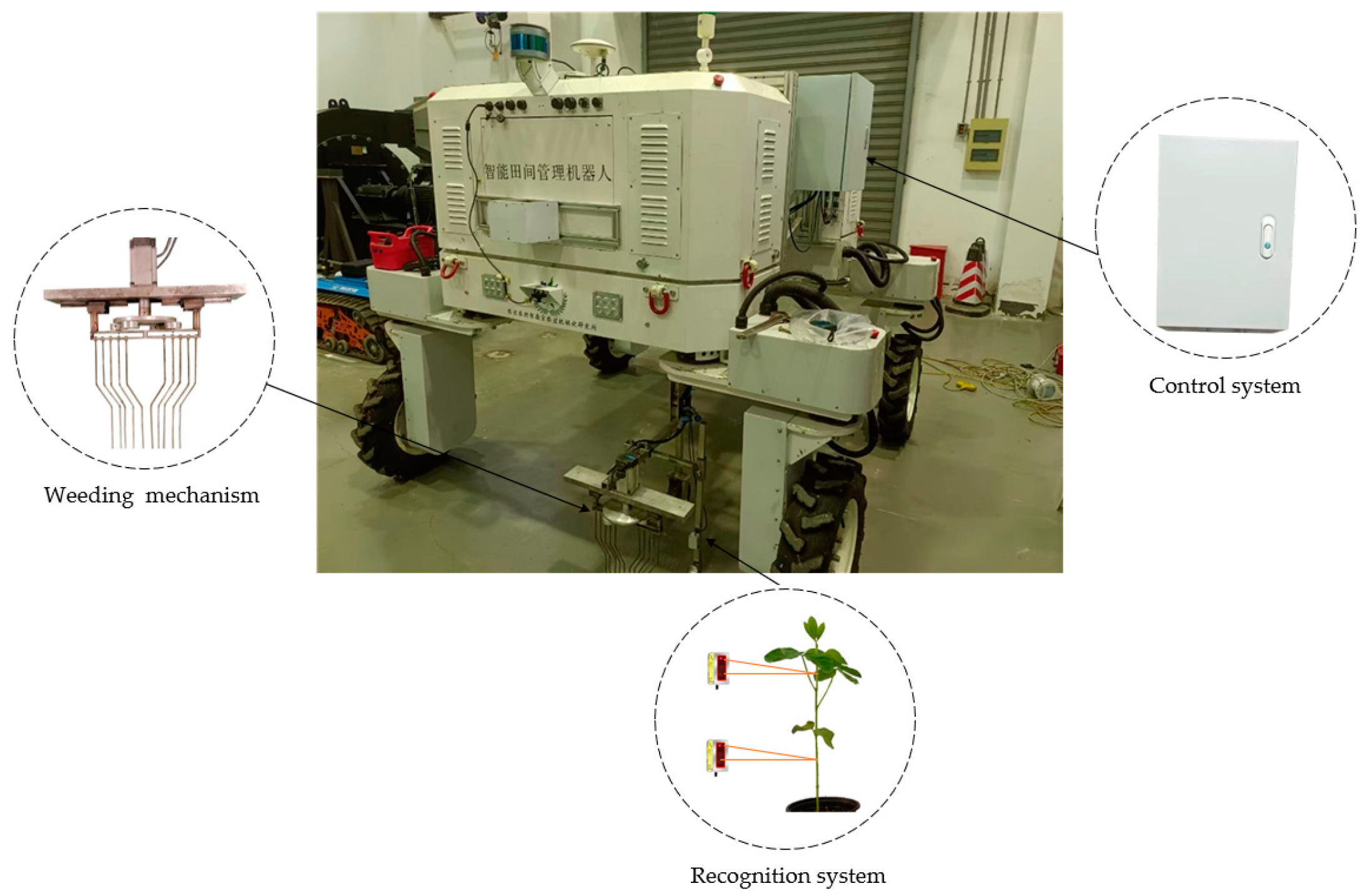
2.1. Weeding Device
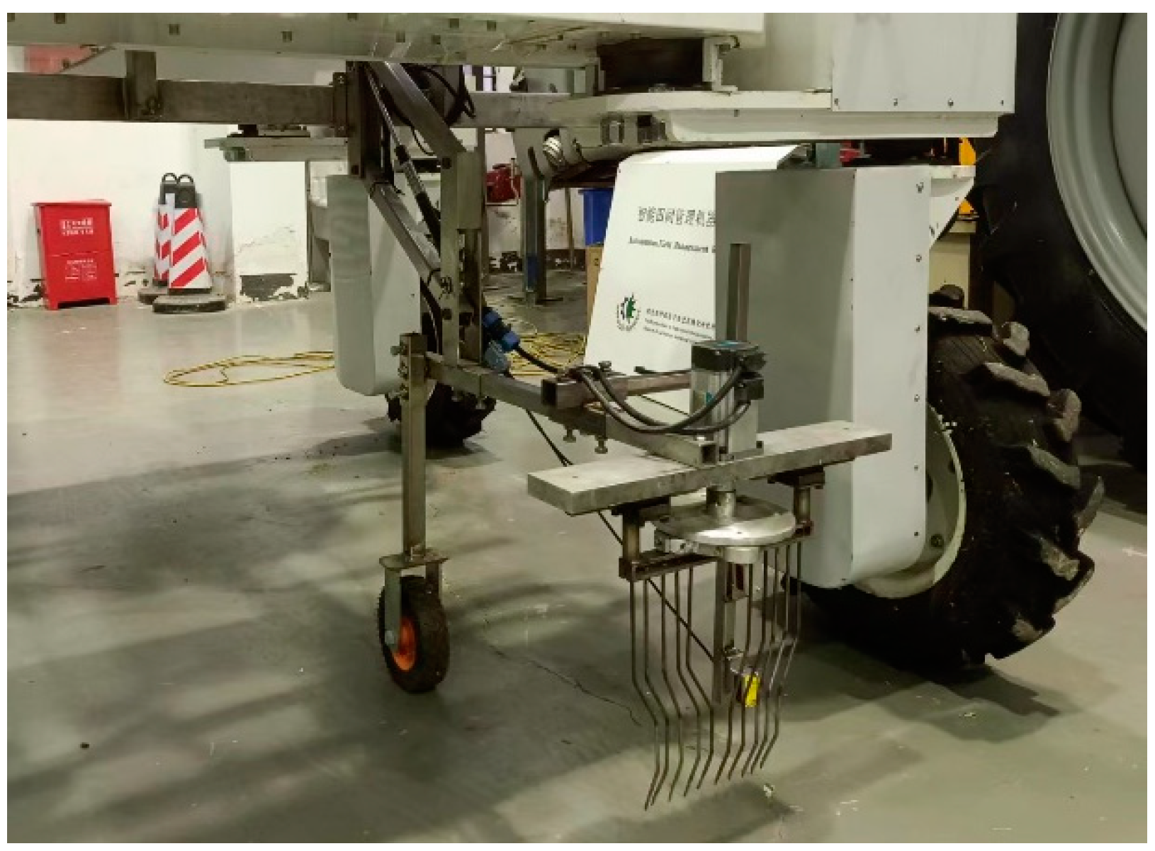
2.1.1. Weeding Mechanism
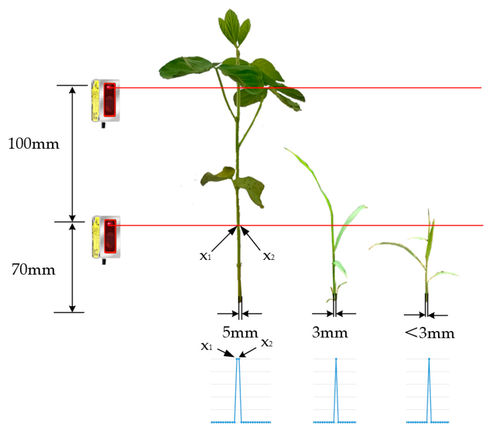
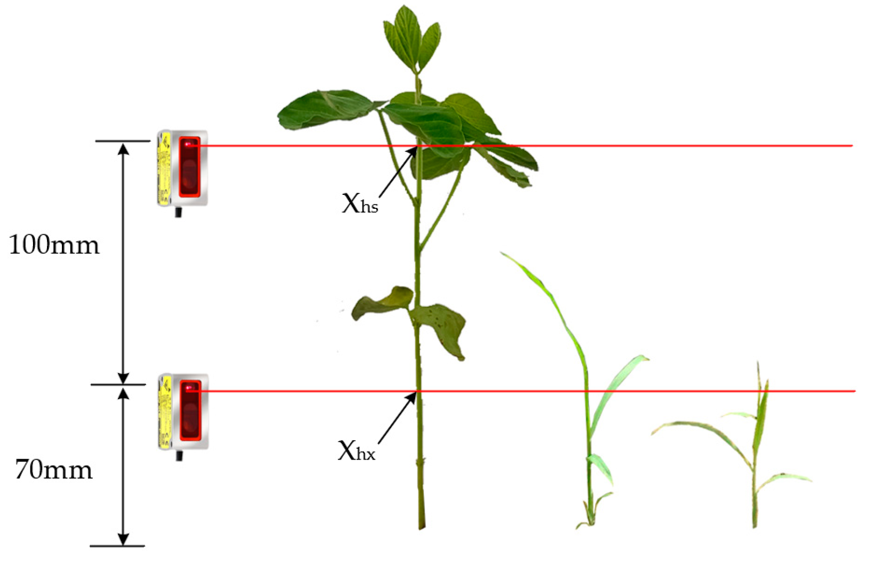
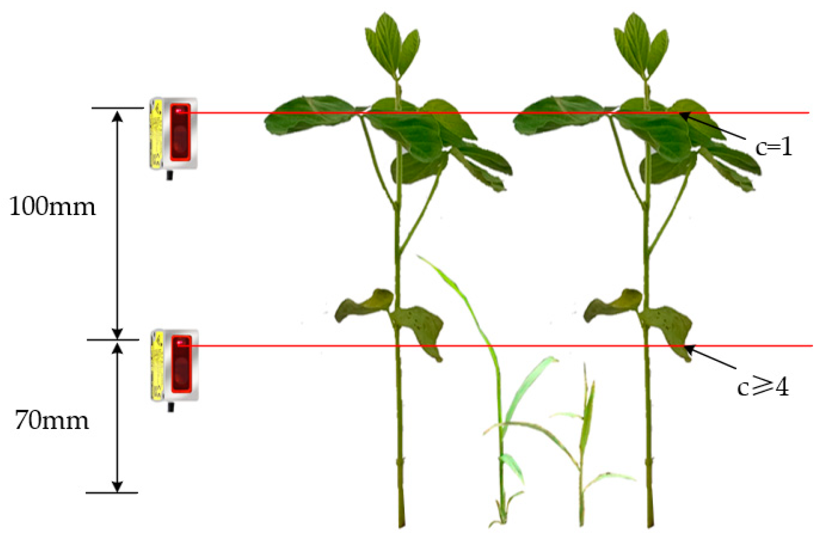
2.1.2. Recognition System and Control System
2.2. Control Methods and Principles of Operation
2.2.1. Control Methods
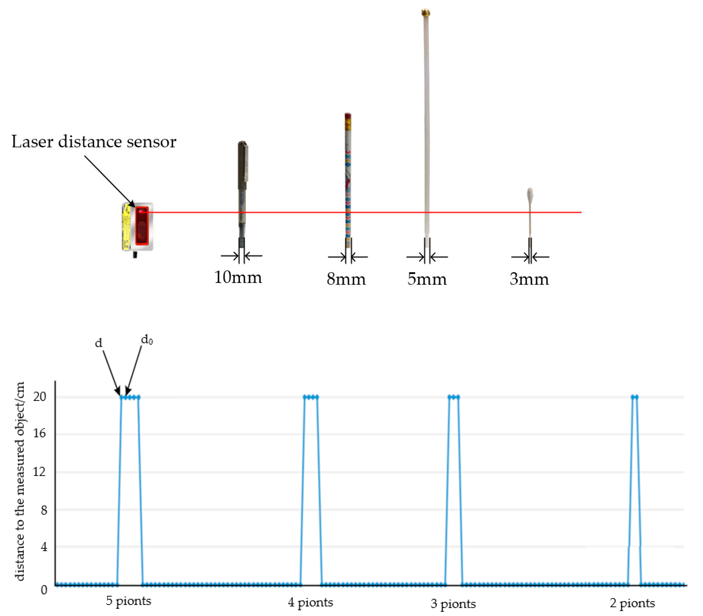
2.2.2. Soybean Plant Recognition Model
3. Design of Weeding Execution Mechanism and Control System
3.1. Weeding Execution Mechanism
3.1.1. Determining Execution Mechanism Parameters
3.1.2. Trajectory Analysis for Seedling Avoidance
3.1.3. Design of Seedling Avoidance Systems
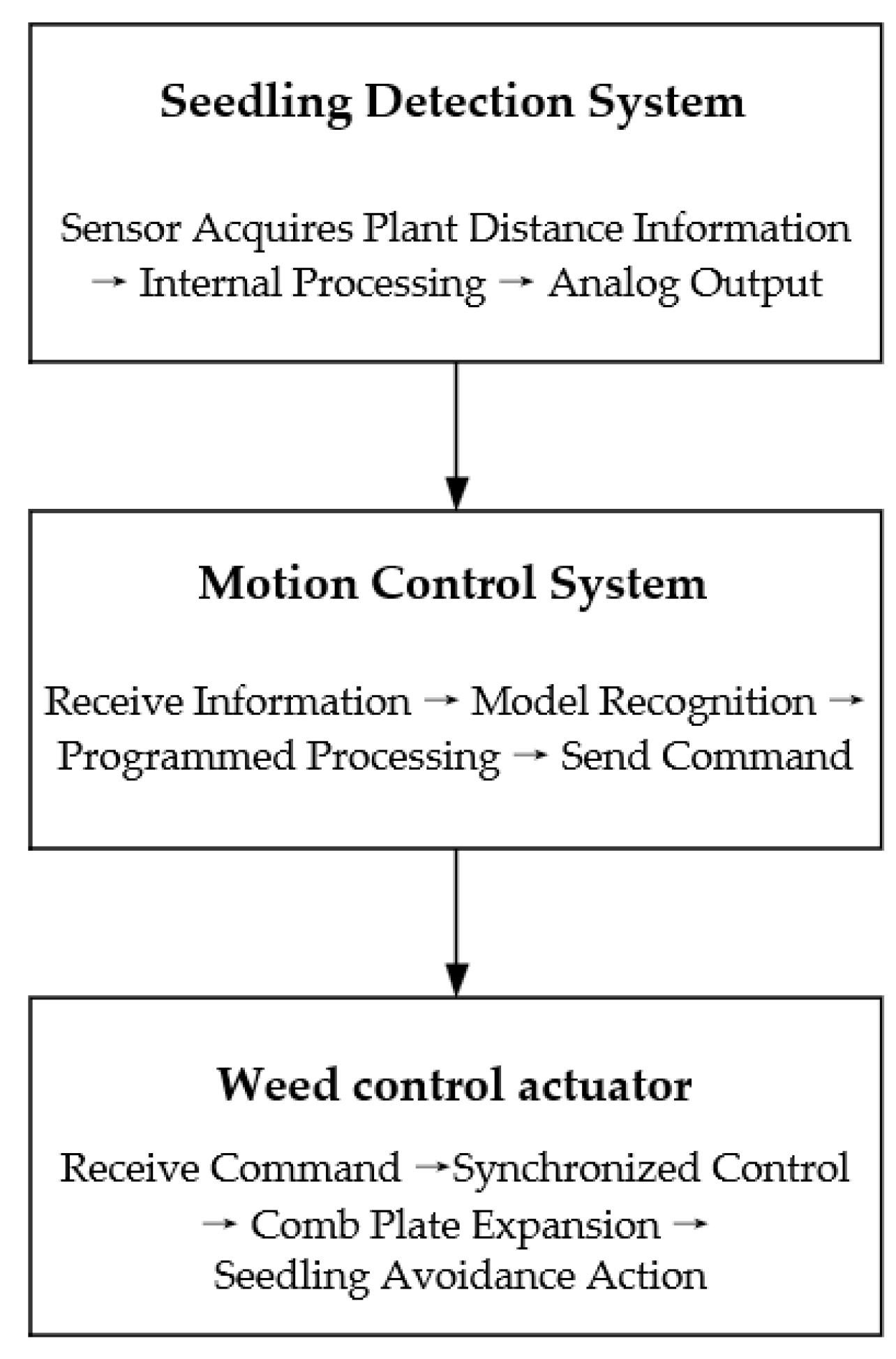
3.2. Control Strategy and Control Steps
4. Field Test
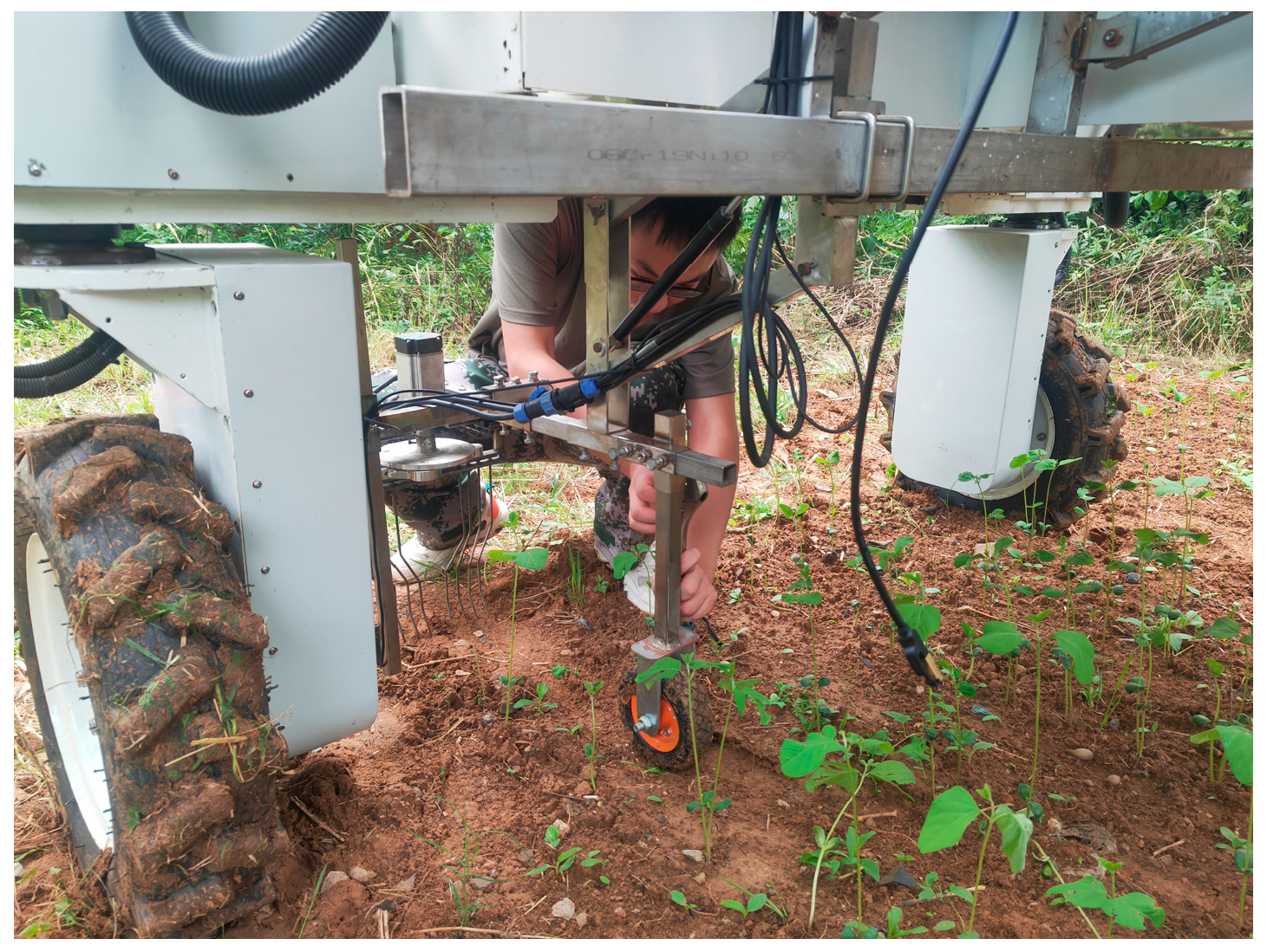
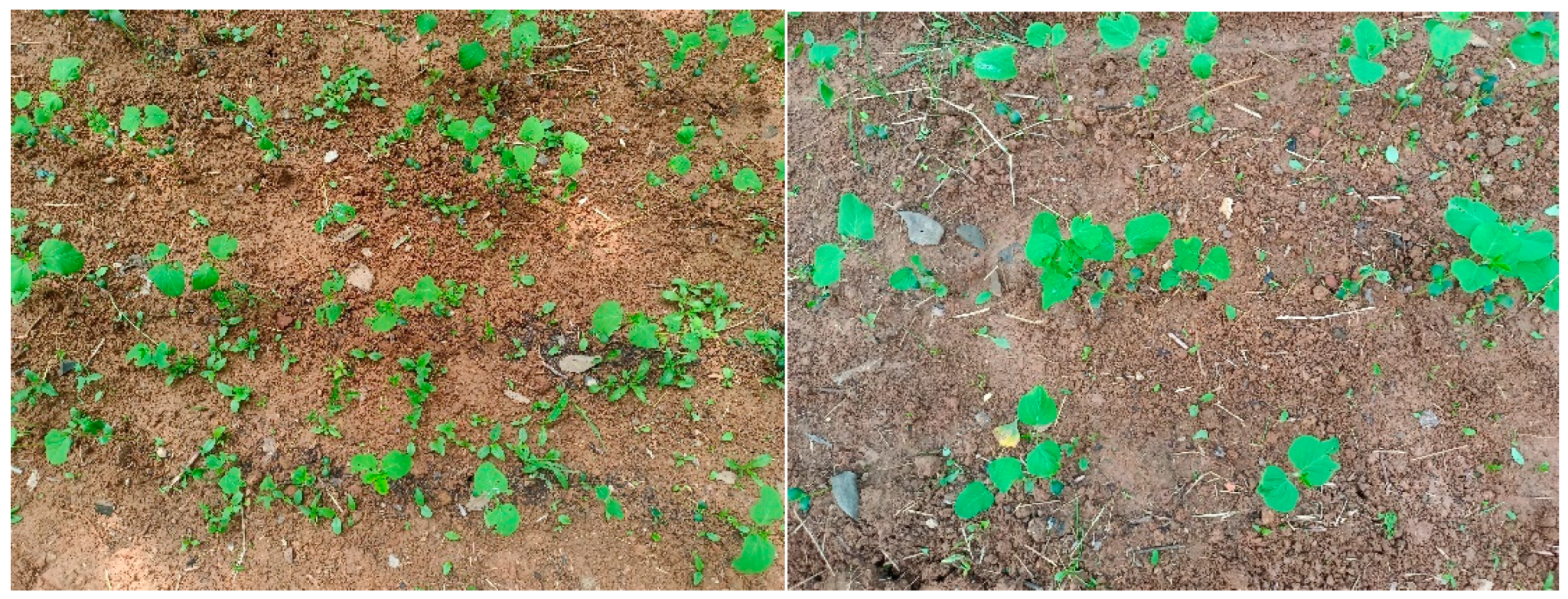
4.1. Test Condition
4.2. Test Program
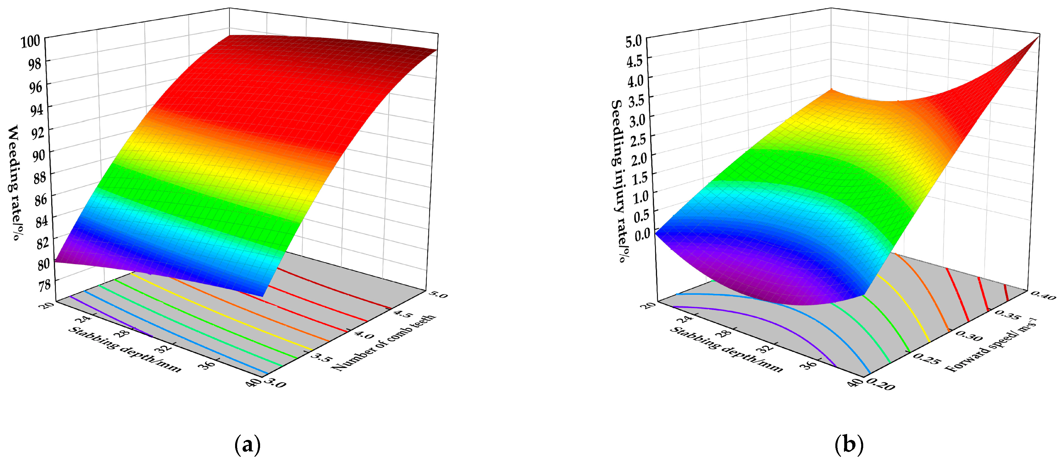
4.3. Analysis of Test Results
4.4. Optimal Operating Parameter Solution
5. Discussion
6. Conclusions
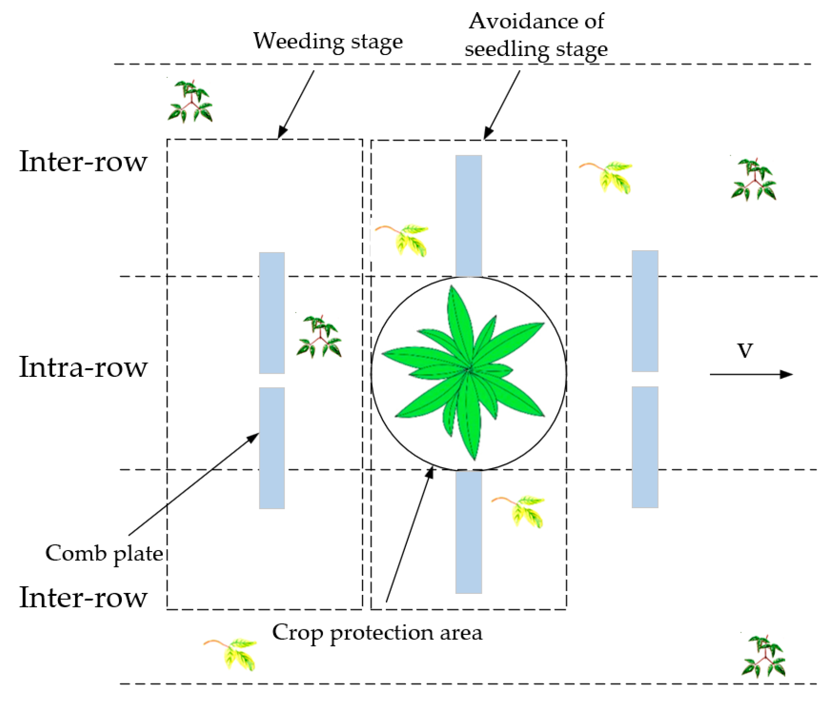
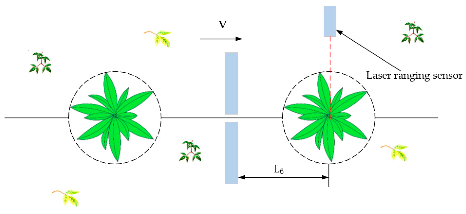
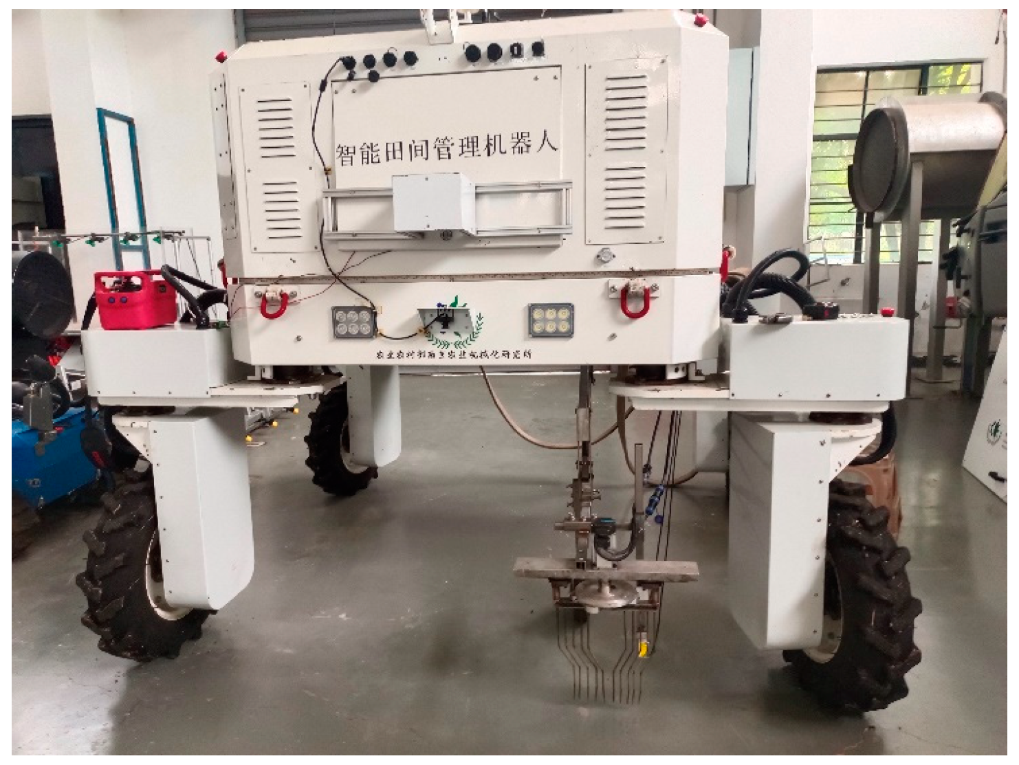
- A reciprocating soybean intra-row weeding device has been designed, which uses intermittent opening and closing of the comb teeth plates to avoid damaging seedlings. It can remove weeds between rows and some weeds within rows. A laser ranging sensor is used as the recognition tool, which has a simple principle and good performance.
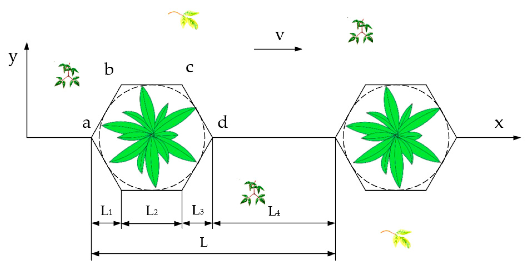
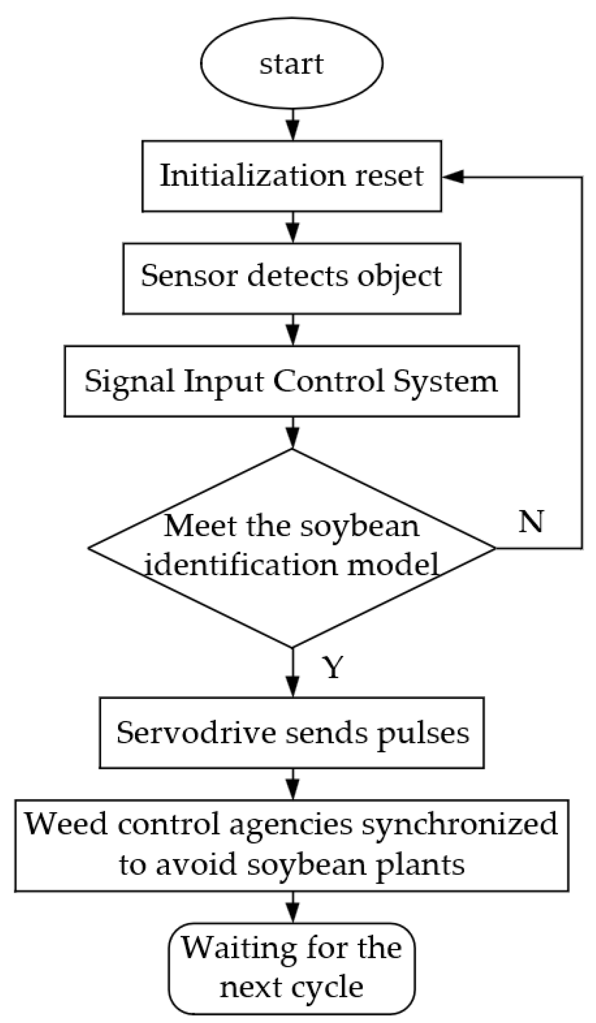
- The critical weeding components of the soybean intra-row weeding machine were analyzed and designed, and the safe range of soybean plants was determined to find the motion trajectory of the elastic comb teeth. The weeding rate is greatly improved while ensuring a low seedling injury rate. Weeding machines are combined with PLC programming and modeling for control, after the sensor detects the distance information of the plants. PLC can synchronize the normal weeding and seedling avoiding operations of the weeding mechanism through the soybean identification model.
- Conducted via field weeding experiments, a quadratic regression universal center of rotation design test was conducted. The three-factor, three-level response surface analysis method was used to establish regression models for the weeding rate and seedling damage rate in relation to the stabbing depth, number of comb teeth, and forward speed. The experimental data were analyzed and optimized using the Design-Expert 8.0.5b software. It is found that the optimal operating performance of the weeding mechanism is achieved when the soil depth is 29.06 mm, the number of comb teeth is 5, and the forward speed is 0.31 m/s. Field performance tests demonstrate that the reciprocating soybean intra-row weeding device designed in this study meets the design requirements and can provide a reference for the design and optimization of soybean field mechanical weeding devices.
Author Contributions
Funding
Institutional Review Board Statement
Informed Consent Statement
Data Availability Statement
Conflicts of Interest
References
- Caldas, J.; Silva, A.; Braz, G.; Procópio, S.; Teixeira, I.; Souza, M.; Reginaldo, L. Weed Competition on Soybean Varieties from Different Relative Maturity Groups. Agriculture 2023, 13, 725. [Google Scholar] [CrossRef]
- Wang, J.; Yan, D.; Wang, Q.; Tang, H.; Wang, J.; Zhou, W. Design and Experiment of Jet-type Paddy Field Weeding Device between Plants. Trans. CSAM 2021, 52, 78–85+94. [Google Scholar]
- Zhao, Z.; Zhu, L.; Zhou, L.; Lv, J.; Li, M.; Dong, X. Design and Experiment of Chassis Control System for Weeding Robot in Hilly Orchard. Trans. CSAM 2022, 53, 48–57. [Google Scholar]
- Xu, L.; Zhao, S.; Ma, S.; Niu, C.; Yan, C.; Lu, C. Optimized design and experiment of the precise obstacle avoidance control system for a grape interplant weeding machine. Trans. Chin. Soc. Agric. Eng. 2021, 37, 31–39. [Google Scholar]
- Zhang, Y.; Wu, M.; Bao, S.; Li, J.; Liu, D.; Dong, L.; Li, J. Detection of Resistance in Echinochloa spp. to Three Post-Emergence Herbicides (Penoxsulam, Metamifop, and Quinclorac) Used in China. Agronomy 2023, 13, 841. [Google Scholar] [CrossRef]
- Xing, Q.; Ding, X.; Xue, X.; Cui, L.; Le, F.; Li, Y. Research on the development status of intelligent field weeding robot. J. Chin. Agric. Mech. 2022, 43, 173–181. [Google Scholar]
- Kumar, N.; Upadhyay, G.; Choudhary, S.; Patel, B.; Naresh; Chhokar, R.; Gill, S. Resource Conserving Mechanization Technologies for Dryland Agriculture. In Enhancing Resilience of Dryland Agriculture Under Changing Climate; Naorem, A., Machiwal, D., Eds.; Springer Nature Singapore: Singapore, 2023; pp. 657–688. [Google Scholar]
- Liu, C. Design and Test of Mechanical Weeding Device for Inter-Row and Intra-Row Synchronization in Paddy Field; South China Agricultural University: Guangzhou, China, 2020. [Google Scholar]
- Ahmad, M. Development of an Automated Mechanical Intra-Row Weeder for Vegetable Crops. Master’s Thesis, The University of Iowa, Iowa City, IA, USA, 2012. [Google Scholar]
- Wang, G.; Liu, H.; Jia, H.; Guo, C.; Cong, Y.; Qu, M. Design and experiment of touching-positioning weeding device for inter-row maize (Zea mays L.). J. Jilin Univ. Eng. Technol. Ed. 2021, 51, 1518–1527. [Google Scholar]
- Quan, L.; Zhang, J.; Jiang, W.; Li, H.; Yang, C.; Zhang, X. Development and Experiment of Intra-row Weeding Robot System Based on Protection of Maize Root System. Trans. CSAM 2021, 52, 115–123. [Google Scholar]
- Slaughter, D.; Giles, D.; Downey, D. Autonomous robotic weed control systems: A review. Comput. Electron. Agric. 2008, 61, 63–78. [Google Scholar] [CrossRef]
- Pérez-Ruíz, M.; Slaughter, D.; Fathallah, F.; Gliever, C.; Miller, B. Co-robotic intra-row weed control system. Biosyst. Eng. 2014, 126, 45–55. [Google Scholar] [CrossRef]
- Cordill, C.; Grift, T. Design and testing of an intra-row mechanical weeding machine for corn. Biosyst. Eng. 2011, 110, 247–252. [Google Scholar] [CrossRef]
- Tillett, N.; Hague, T.; Grundy, A.; Dedousis, A. Mechanical within-row weed control for transplanted crops using computer vision. Biosyst. Eng. 2008, 99, 171–178. [Google Scholar] [CrossRef]
- Hu, L.; Luo, X.; Yan, Y. Development and experiment of intra-row mechanical weeding device based on trochoid motion of claw tooth. Trans. Chin. Soc. Agric. Eng. 2012, 28, 10–16. [Google Scholar]
- Chen, Z.; Li, N.; Sun, Z.; Li, T.; Zhang, C.; Li, W. Optimization and Experiment of Intra-row Brush Weeding Manipulator Based on Planetary Gear Train. Trans. CSAM 2015, 46, 94–99. [Google Scholar]
- Jia, H.; Li, S.; Wang, G.; Liu, H. Design and experiment of seedling avoidable weeding control device for intertillage maize (Zea mays L.). Trans. Chin. Soc. Agric. Eng. 2018, 34, 15–22. [Google Scholar]
- Zhang, D.; Yang, Y.; Huang, L.; Yang, Q.; Liang, D.; She, B.; Hong, Q.; Jiang, F. Extraction of soybean planting areas combining Sentinel-2 images and optimized feature model. Trans. Chin. Soc. Agric. Eng. 2021, 37, 110–119. [Google Scholar]
- Danilov, R.; Kremneva, O.; Pachkin, A. Identification of the Spectral Patterns of Cultivated Plants and Weeds: Hyperspectral Vegetation Indices. Agronomy 2023, 13, 859. [Google Scholar] [CrossRef]
- Sun, Z.; Zhang, C.; Ge, L.; Zhang, M.; Li, W.; Tan, Y. Image Detection Method for Broccoli Seedlings in Field Based on Faster R-CNN. Trans. CSAM 2019, 50, 216–221. [Google Scholar]
- He, Y.; Wang, Z.; Wang, X.; Xiao, J.; Luo, Y.; Zhang, J. Research progress of deep learning in crop disease image recognition. J. Chin. Agric. Mech. 2023, 44, 148–155. [Google Scholar]
- Albahar, M. A Survey on Deep Learning and Its Impact on Agriculture: Challenges and Opportunities. Agriculture 2023, 13, 540. [Google Scholar] [CrossRef]
- Ullah, Z.; Alsubaie, N.; Jamjoom, M.; Alajmani, S.; Saleem, F. EffiMob-Net: A Deep Learning-Based Hybrid Model for Detection and Identification of Tomato Diseases Using Leaf Images. Agriculture 2023, 13, 737. [Google Scholar] [CrossRef]
- Quan, L.; Wang, Q.; Zhang, J.; Feng, H.; Wu, B. Design and testing of intelligent intra-row mechanical weeding equipment based on vertical rotating mechanism. J. Jiangsu Univ. Nat. Sci. Ed. 2021, 42, 582–588. [Google Scholar]
- Wang, Y.; Hu, Y.; Kong, Q.; Zeng, H.; Zhang, L.; Fan, B. 3D point cloud semantic segmentation: State of the art and challenges. Chin. J. Eng. 2023, 45, 1653–1665. [Google Scholar]
- Wang, J.; Yang, H.; Chen, Y.; Zhou, X.; Jiang, Y.; Zhang, J. Application analysis of domestic copying technology in agricultural machinery. J. Chin. Agric. Mech. 2023, 44, 31–39. [Google Scholar]


| Level | Stabbing Depth/mm | Number of Comb Teeth | Forward Speed/(m·s−1) |
|---|---|---|---|
| 1 | 20 | 3 | 0.2 |
| 2 | 30 | 4 | 0.3 |
| 3 | 40 | 5 | 0.4 |
| Test Number | Stabbing Depth/mm | Number of Comb Teeth | Forward Speed/(m·s−1) | Weeding Rate/% | Seedling Injury Rate/% |
|---|---|---|---|---|---|
| 1 | 20 | 4 | 0.3 | 91.24 | 1.18 |
| 2 | 30 | 4 | 0.3 | 92.17 | 1.70 |
| 3 | 40 | 3 | 0.4 | 82.95 | 5.17 |
| 4 | 40 | 4 | 0.3 | 93.09 | 2.91 |
| 5 | 30 | 5 | 0.3 | 97.70 | 1.69 |
| 6 | 30 | 4 | 0.3 | 92.17 | 1.19 |
| 7 | 40 | 5 | 0.4 | 98.62 | 5.71 |
| 8 | 20 | 3 | 0.2 | 79.26 | 0.00 |
| 9 | 30 | 4 | 0.2 | 92.63 | 0.00 |
| 10 | 20 | 5 | 0.4 | 96.77 | 3.51 |
| 11 | 20 | 5 | 0.2 | 97.70 | 0.00 |
| 12 | 30 | 3 | 0.3 | 82.03 | 1.14 |
| 13 | 30 | 4 | 0.4 | 92.17 | 1.83 |
| 14 | 40 | 5 | 0.2 | 98.62 | 0.00 |
| 15 | 30 | 4 | 0.3 | 93.09 | 1.16 |
| 16 | 20 | 3 | 0.4 | 79.72 | 2.89 |
| 17 | 40 | 3 | 0.2 | 82.03 | 0.00 |
| 18 | 30 | 4 | 0.3 | 93.09 | 1.19 |
| 19 | 30 | 4 | 0.3 | 92.63 | 0.59 |
| 20 | 30 | 4 | 0.3 | 93.09 | 1.15 |
| Variance Source | Degree of Freedom | Sum of Squares | Mean Square | F Value | p Value | ||||
|---|---|---|---|---|---|---|---|---|---|
| RC | RS | RC | RS | RC | RS | RC | RS | ||
| Model | 9 | 754.68 | 48.38 | 83.85 | 5.38 | 427.61 | 16.33 | <0.0001 | <0.0001 |
| A | 1 | 11.23 | 3.87 | 11.23 | 3.87 | 57.29 | 11.75 | <0.0001 | 0.0065 |
| B | 1 | 695.73 | 0.29 | 695.73 | 0.29 | 3547.83 | 0.89 | <0.0001 | 0.3683 |
| C | 1 | 0 | 36.54 | 0 | 36.54 | 0 | 111 | 1.0000 | <0.0001 |
| AB | 1 | 1.30 | 0.00074 | 1.30 | 0.00074 | 6.63 | 0.0022 | 0.0276 | 0.9632 |
| AC | 1 | 0.24 | 2.52 | 0.24 | 2.52 | 1.22 | 7.65 | 0.2955 | 0.0199 |
| BC | 1 | 0.66 | 0.17 | 0.66 | 0.17 | 3.38 | 0.51 | 0.0957 | 0.4909 |
| A2 | 1 | 0.39 | 2.34 | 0.39 | 2.34 | 1.99 | 7.10 | 0.1883 | 0.0237 |
| B2 | 1 | 19.77 | 0.23 | 19.77 | 0.23 | 100.81 | 0.71 | <0.0001 | 0.4200 |
| C2 | 1 | 0.059 | 0.12 | 0.059 | 0.12 | 0.30 | 0.35 | 0.5950 | 0.5661 |
| Residual | 10 | 1.96 | 3.29 | 0.20 | 0.33 | ||||
| Lack of fit | 5 | 0.93 | 2.67 | 0.19 | 0.53 | 0.91 | 4.26 | 0.5397 | 0.0687 |
| Pure terror | 5 | 1.03 | 0.63 | 0.21 | 0.13 | ||||
| Cor total | 19 | 756.64 | 51.67 | ||||||
| Stabbing Depth/mm | Number of Comb Teeth | Forward Speed/(m·s−1) | Weeding Rate/% | Seedling Injury Rate/% |
|---|---|---|---|---|
| 29 | 5 | 0.3 | 97.24 | 1.15 |
| 97.24 | 1.75 | |||
| 96.77 | 1.17 | |||
| 98.16 | 2.30 | |||
| 97.70 | 1.70 |
Disclaimer/Publisher’s Note: The statements, opinions and data contained in all publications are solely those of the individual author(s) and contributor(s) and not of MDPI and/or the editor(s). MDPI and/or the editor(s) disclaim responsibility for any injury to people or property resulting from any ideas, methods, instructions or products referred to in the content. |
© 2023 by the authors. Licensee MDPI, Basel, Switzerland. This article is an open access article distributed under the terms and conditions of the Creative Commons Attribution (CC BY) license (https://creativecommons.org/licenses/by/4.0/).
Share and Cite
Ye, S.; Xue, X.; Si, S.; Xu, Y.; Le, F.; Cui, L.; Jin, Y. Design and Testing of an Elastic Comb Reciprocating a Soybean Plant-to-Plant Seedling Avoidance and Weeding Device. Agriculture 2023, 13, 2157. https://doi.org/10.3390/agriculture13112157
Ye S, Xue X, Si S, Xu Y, Le F, Cui L, Jin Y. Design and Testing of an Elastic Comb Reciprocating a Soybean Plant-to-Plant Seedling Avoidance and Weeding Device. Agriculture. 2023; 13(11):2157. https://doi.org/10.3390/agriculture13112157
Chicago/Turabian StyleYe, Shenghao, Xinyu Xue, Shuning Si, Yang Xu, Feixiang Le, Longfei Cui, and Yongkui Jin. 2023. "Design and Testing of an Elastic Comb Reciprocating a Soybean Plant-to-Plant Seedling Avoidance and Weeding Device" Agriculture 13, no. 11: 2157. https://doi.org/10.3390/agriculture13112157