Article

Stress Simulation on Cam-Type Transplanting Device of Semiautomatic Vegetable Transplanter

1
Department of Agricultural and Biosystems Engineering, Faculty of Agricultural Technology, Universitas Gadjah Mada, Yogyakarta 55281, Indonesia
2
Department of Biosystems Engineering, Kangwon National University, Chuncheon 24341, Republic of Korea
3
Interdisciplinary Program in Smart Agriculture, Kangwon National University, Chuncheon 24341, Republic of Korea
*
Author to whom correspondence should be addressed.
These authors contributed equally to this work.
Agriculture 2023, 13(12), 2230; https://doi.org/10.3390/agriculture13122230
Submission received: 24 October 2023 / Revised: 28 November 2023 / Accepted: 29 November 2023 / Published: 1 December 2023
(This article belongs to the Special Issue Advances in Modern Agricultural Machinery)

Abstract

:
Stress measurements play a crucial role in safety analyses of transplanting devices. Strain gauges for stress measurements during field tests can be expensive and time-consuming. The aim of this study was to investigate the stress on the transplanting device of a cam-type semiautomatic vegetable transplanter using a simulation method. A three-dimensional simulation model was established, considering the dimensions and material properties of the transplanting device. The stress distribution and maximum stress values were obtained through simulations. The maximum stress values at 15 points within the transplanting device determined via the simulation were compared with the experimental stress data to verify the stress simulation model. The results show that the maximum stress obtained from the simulation correlated with that of the measured results, although differences were observed at different locations, particularly at strain gauge positions 11 and 13. Based on the simulation results, the maximum stress occurs at the upper link of the cam-type transplanting device, reaching a magnitude of 201.21 MPa, and the static safety factor is 1.04.

1. Introduction

The modernization of agricultural practices has led to the development of specialized machinery to optimize various aspects of crop cultivation. Among these innovations, the vegetable transplanter is a pivotal advancement in addressing challenges, such as labor shortages and rising production costs in vegetable farming [1,2]. A vegetable transplanter is a machine used to plant vegetable seedlings into the ground. Based on the method for extracting the seedling and its placement within the seedling cylinder, the vegetable transplanter is categorized into two types as semiautomatic and fully automatic. In the case of a fully automatic vegetable transplanter, the seedlings are automatically supplied and put into the seedling cylinder. Conversely, in a semiautomatic vegetable transplanter, the operator manually supplies the seedling and places them within the seedling cylinder, necessitating human intervention in the seedling handling process [3,4].
The primary component of a vegetable transplanter is the transplanting device, which is responsible for planting seedlings in the soil. There are several types of vegetable transplanter that have been developed based on the design of the transplanting device, namely wheel, rotary, four-bar-link, and cam types [5,6,7]. Among the various developed types, the cam mechanism is widely used. The cam type employs a cam that opens and closes the hopper by contacting the bearing. This type is particularly suited for small cultivation areas because of its simple design and user-friendly operation [8,9,10].
The transplanting device is subjected to significant mechanical stresses during its operational cycles. These stresses, arising from the demanding conditions of field operations, can potentially lead to material fatigue, diminished performance, and safety hazards within the transplanting service [11,12,13]. Sri et al. [14] conducted load and safety analyses to ensure the safety of the transplanting device of a cam-type semiautomatic vegetable transplanter. The safety analysis involved measuring the strain at several points on the transplanting device using a strain gauge. Subsequently, the measured strain data were converted into stress data to calculate the static safety factor and fatigue life. The experiments were carried out using four different engine speeds and twelve planting distances. The findings revealed that as the engine speed increased or the planting distance decreased, the stress on the transplanting device tended to increase. The cam-type transplanting device demonstrated static safety factors exceeding 1.0 across all measurement points and under various working conditions. At the upper section of the hopper, the minimum fatigue life was determined to be 66,416 h. This is considered an ample lifespan, especially when taking into account the annual usage time of 25.5 h in Korea.
The initial step in the load and safety analysis of a machine component is stress determinative [15,16]. The prevalent technique for measuring stress in machine parts involves using sensors, such as strain gauges and load cells in field tests [17,18,19]. The sensor can measure stress exclusively at a specific location. Numerous sensors must be installed to assess the stress levels at multiple points. Consequently, the use of sensors for measuring stress can be expensive and time-consuming [20,21]. A potential solution to this problem is to conduct stress simulations.
Stress simulation entails the utilization of software or computer programs to emulate and analyze the stress experienced by various components of a machine. Numerous studies have been conducted on stress simulations of various types of agricultural machinery. Plouffe et al. [22] investigated the influence of various components and adjustments on the performance of a moldboard plow operating on clay soil by combining modeling applied with the finite element method (FEM) and incorporating experimental observations. Makange et al. [23] performed a FEM analysis on a nine-tine cultivator to recognize potential weaknesses within the shovel element under varying loads and speeds in medium-black soil. The findings indicated that the highest and lowest principal stresses registered at 5.1726 and 0.20944 megapascals (MPa), respectively, along with a total deformation of 0.076953 mm. Importantly, the maximum stress remained below the yield point, indicating that the deformation did not lead to failure in the tine. Similarly, Yurdem et al. [24] conducted their research on a three-bottom moldboard plow to assess the stresses through field measurements using strain gauges affixed to various sections of the moldboard frame. These measurements were then verified with the outcomes derived from finite element simulations. The study concluded that the decreased thickness of the moldboard frame did not lead to undue stresses, and the observed strains closely matched the simulated data. Kesner et al. [25] established a computational model of a tillage machine to analyze these loads. The result showed that the experimental stress measurements aligned well with the simulation data obtained from the model. Consequently, the methods employed in this study can be applied in designing and refining tillage machinery. Islam et al. [26] analyzed the stress resisted by the gear mechanism within the picking device of an automatic pepper transplanter to determine optimal materials and dimensions and predict the fatigue life based on damage assessment. Both the crank and cam gear sets underwent testing using finite element analysis simulation and stress analysis theory based on the American Gear Manufacturers Association standard. These tests were performed with various materials and dimensions. The findings from this research act as a valuable reference for designing the picking device gears with optimal material characteristics, ensuring the recommended service life of pepper-planting equipment. However, from all the research that has been carried out, a virtual model for stress simulations that specifically focuses on cam-type transplanting devices has not yet been developed, to the best of our knowledge.
The aim of this study was to investigate the stress distribution and analyze the safety of cam-type transplanting devices for semiautomatic vegetable transplanters using simulations. The specific objectives were to (1) establish a three-dimensional model of the transplanting device using commercial dynamic simulation software, (2) conduct a simulation-based analysis of stress distribution, maximum stress levels, and the static safety factor associated with the transplanting device, and (3) validate the precision of the established virtual model by contrasting simulation results with experimental data. The results of this study have the potential to provide valuable insights for the manufacturers and designers of transplanting devices, enhancing safety, performance, and reliability. In addition, the results of this study can be used as basic data to establish the design process or design guidelines for cam-type planting devices.

2. Materials and Methods

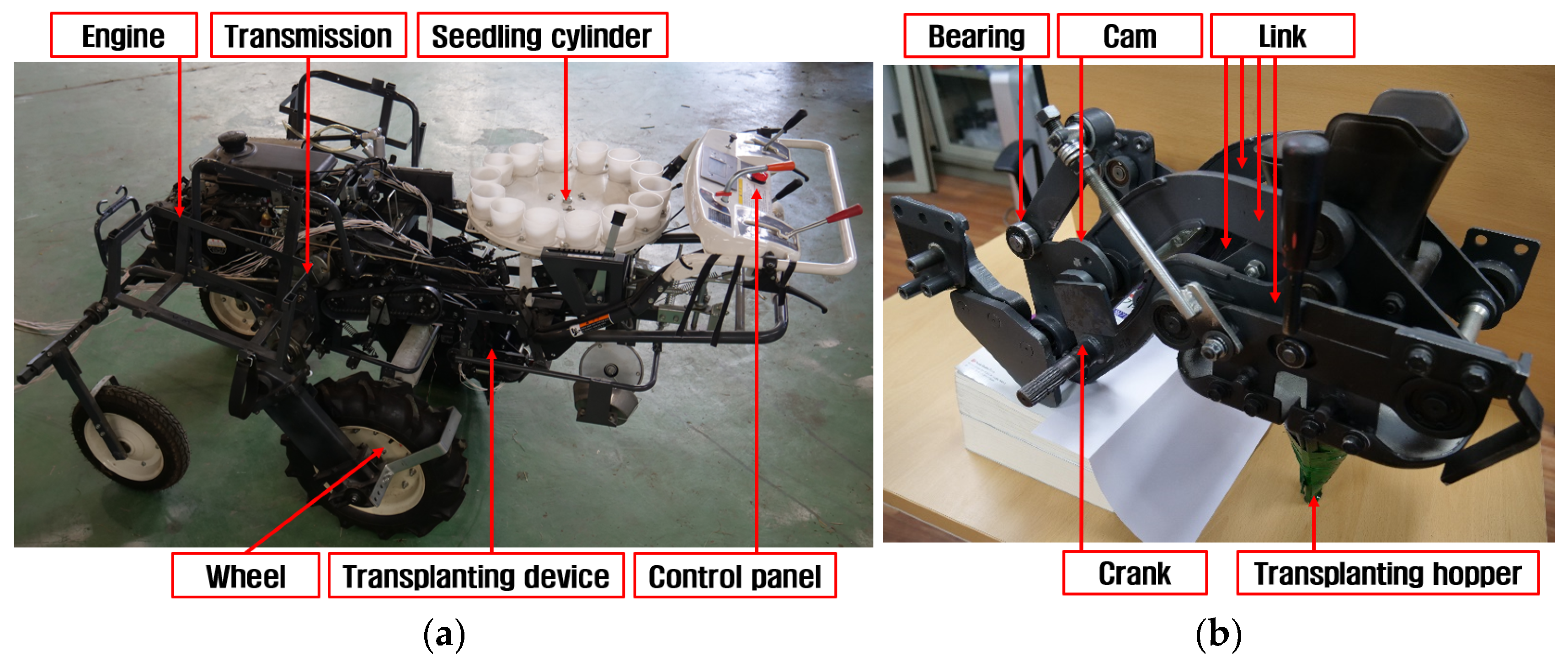
2.1. Transplanting Device of Cam-Type Vegetable Transplanter [7]

The shape and specifications of the cam-type vegetable transplanter used in this study are presented in Figure 1 and Table 1, respectively. The cam-type vegetable transplanter consisted of an engine for supplying power, a transmission for transferring power to the wheel and transplanting device, a control panel for adjusting plant spacing and depth, a seedling cylinder designed for seedling placement, and a transplanting device for planting the seedlings supplied from the seedling cylinder into the soil.
The transplanter with the cam-type transplanting device operates as follows: A user determines the travel speed and the spacing in the row of the transplanter. Then the seedlings are supplied to the seedling cylinders manually. The transplanter moves and plants the seedlings into the ground by the motion of the transplanting device. That motion makes the transplanting hopper of the cam-type transplanting device move up and down in a certain trajectory. When the hopper is at the top, it is located below one of the seedling cylinders, the seedling cylinder opens and drops the seedling into the transplanting hopper. When the transplanting hopper comes to the lower end, it is located at a certain depth in the ground. At that moment, the seedlings are planted into the ground after the opening of the transplanting hopper. The row spacing suitable for the target crop can be set by the control panel. The seedlings planted in the ground are covered with soil, and the transplanting work is complete. During the transplanting process, the mechanical operations of the transplanter generate loads on the transplanting device. The main components of the transplanting device in this study were links, bearings, a cam, a crank, and a transplanting hopper. The links played a role in determining the trajectory of the transplanting hopper. The crank supplied the power transmitted from the engine and transmission to the transplanting device. The shape of the cam had an influence on the behavior of the planting hopper. Therefore, the cycle of opening and closing the planting hopper was determined mechanically due to the contact between the bearing and the cam. The material properties of the transplanting device are listed in Table 2.

2.2. Stress Measurement

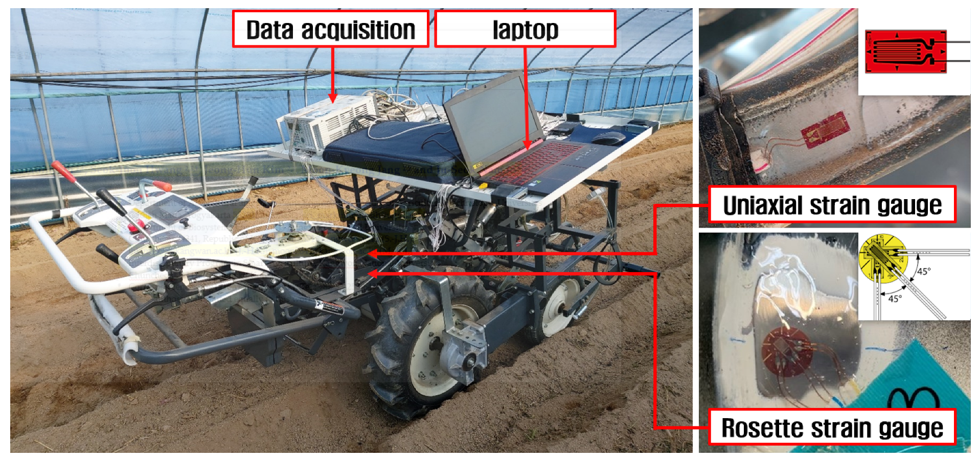
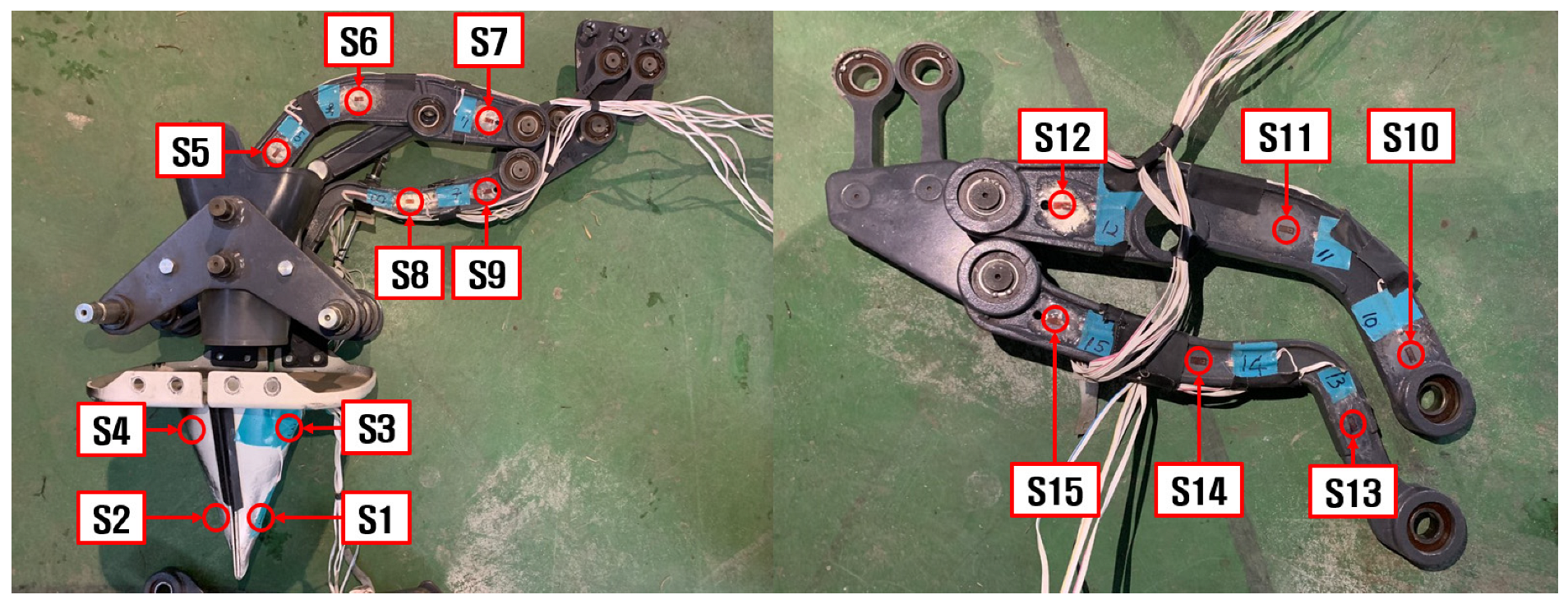
2.2.1. Stress Measurement System

A stress measurement system was constructed to measure the stress exerted on the transplanting device, as shown in Figure 2. The stress measurement system consisted of strain gauges, a data acquisition system (TG009E, HBK, Darmstadt, Germany), and a laptop. The strain data measured using the strain gauges were transmitted to a data acquisition unit and recorded on a laptop. Two types of strain gauges were used to obtain strain data for the transplanting device links. One was a uniaxial strain gauge (KFGS-5-350-C1-11 L10M3R, KYOWA, Tokyo, Japan), which is suitable for measuring the strain in a singular direction, making it well suited for scenarios where a primary loading direction is evident, such as in axial bars or links. The second was a rosette strain gauge (KFGS-1-350-D17-11 L5M3S, KYOWA, Tokyo, Japan) that featured three strain gauges positioned at 45° intervals. The rosette strain gauge is optimal for measuring areas where the main loading direction is unknown because it encompasses three strain gauges positioned at distinct angles. Figure 3 shows the installation locations of the 13 uniaxial strain gauges (S1–S2 and S5–S15) and 2 rosette strain gauges (S3 and S4). Two uniaxial strain gauges (S1 and S2) were attached to the end of the transplanting hopper. The rosette strain gauges (S3 and S4) were attached to the curved upper part on either side of the transplanting hopper. The uniaxial strain gauges of S5, S6, and S7 were attached to the left, center, and right sides of the left upper link, respectively. Uniaxial strain gauges (S10, S11, and S12) were attached on the right upper link in the same positions as those on the left upper link. Two uniaxial strain gauges (S8 and S9) were attached to the left bottom link, and three uniaxial strain gauges (S13, S14, and S15) were attached to the bottom right link. The specifications of the strain gauges and data acquisition are listed in Table 3 and Table 4, respectively.

2.2.2. Working Conditions

The field test took place in a field featuring consistent soil conditions, situated at coordinates 37°56′24.0″ N and 127°46′59.1″ E. The location has an elevation of 111.00 m above sea level and is located in Sinbuk-eup, Chuncheon, within Gangwon Province, South Korea. The length, width, and depth of the test bed were 45, 0.6, and 0.3 m, respectively. Prior to the experiments, the soil was tilled using a plow and a rotavator, considering the actual working conditions of the vegetable transplanter. Therefore, the soil of the transplanting ridge is extremely soft. And the variation of planting depth is less than the hardpan depth of the test bed. The vegetable transplanter worked at an engine speed of 1550 RPM with a set planting distance of 0.5 m and a set planting depth of 0.07 m. The test was performed in triplicate, and the data were analyzed using the average as a representative value.

2.2.3. Analysis Data

The strain data acquired during the field tests were converted to stress values. This conversion depended on the specific type of strain gauge used, resulting in two distinct categories of strain data. The stress was calculated by multiplying the strain data derived from the uniaxial strain gauge by the modulus of elasticity, as expressed by Equation (1). In contrast, the rosette strain gauge was capable of measuring strains along three different axes. By using the strain values recorded for each direction, significant stress values, such as the maximum and minimum principal stresses and the von Mises stress, can be calculated using Equations (2)–(5) [14]:
σ = E × ε
σ 1 = E 2 ( 1 v 2 ) 1 + v ε a + ε c + 1 v × 2 ( ε a ε b ) 2 + ( ε b ε c ) 2
σ 2 = E 2 ( 1 v 2 ) 1 + v ε a + ε c 1 v × 2 ( ε a ε b ) 2 + ( ε b ε c ) 2
σ v = σ 1 2 σ 1 σ 2 + σ 2 2
τ m a x = E 2 ( 1 + v ) × 2 ( ε a ε b ) 2 + ( ε b ε c ) 2
where σ is the calculated axial stress (Pa), σ 1 is the maximum principal stress (Pa), σ 2 is the minimum principal stress (Pa), σ v is the von Mises stress (Pa), ε is the measured strain for the components of the transplanting device, E is the modulus of elasticity (Pa), ν is Poisson’s ratio, τmax is the maximum shear stress (Pa), εa is the measured strain in the horizontal direction in the rosette strain, εb is the measured strain in the 45° direction in the rosette strain, and εc is the measured strain in the vertical direction in the rosette strain.

2.3. Stress Simulation

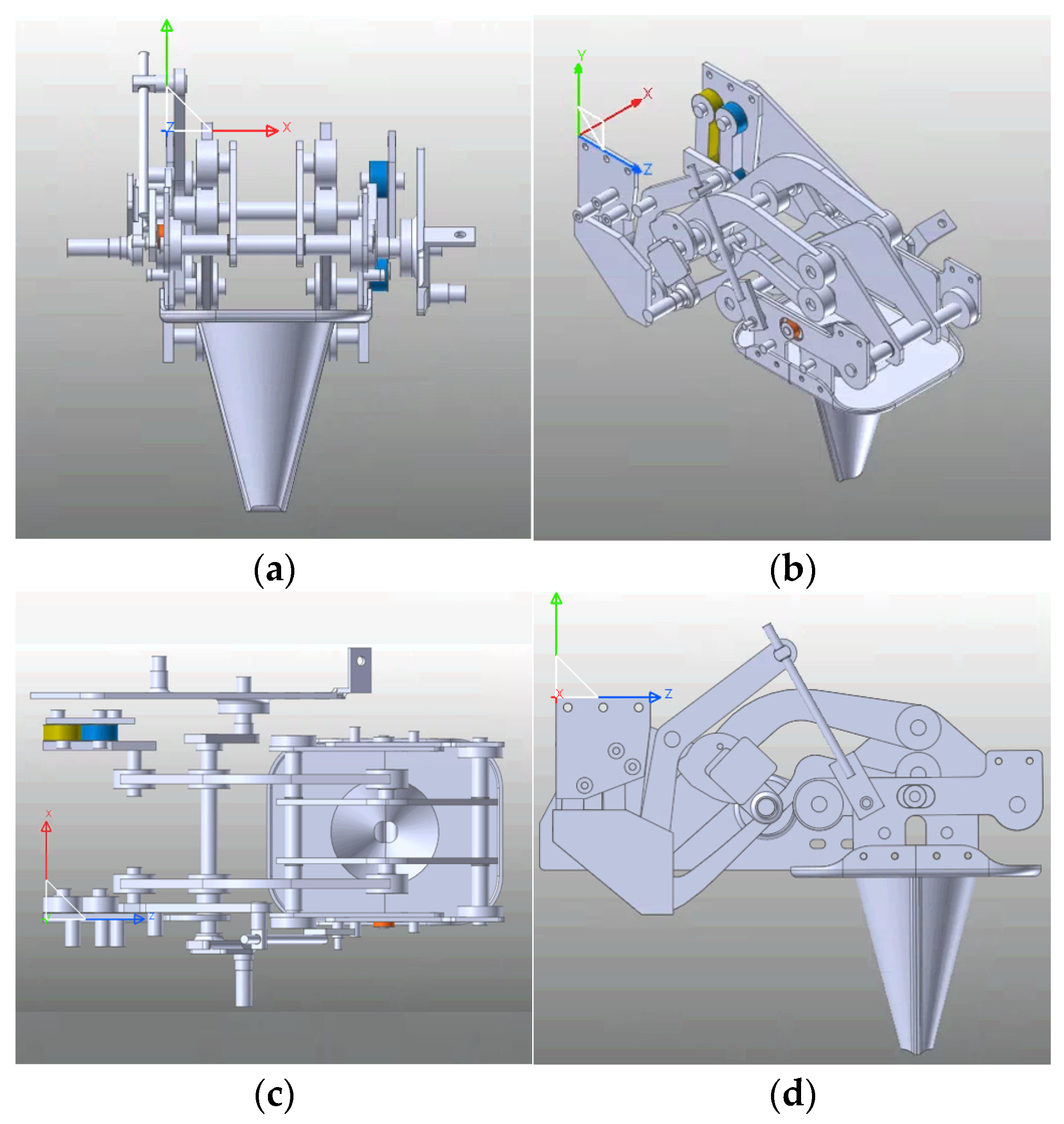
2.3.1. Simulation Model

A dynamic simulation was performed using commercial software (Recurdyn V9R4, Functionbay, Seongnam, Republic of Korea) to derive the stress exerted on the transplanting device. This software is widely used in studies on predicting forces and loads within diverse multibody systems comprising rigid and flexible components. Figure 4 depicts a 3D model of the cam-type transplanting device. A 3D model of the transplantation device was developed, considering its actual dimensions and material properties.

2.3.2. Simulation Condition

The simulation model for determining the stress exerted by the contact between the transplanting hopper and the ground is shown in Figure 5. The simulation conditions were set as an engine speed of 1550 rpm, a planting distance of 0.5 m, and a planting depth of 0.07 m, which yielded the maximum stress during the experiments. Therefore, in the simulation, the components of the transplanting device were operated by the behavior of the rotated cam with the 1550 rpm angular speed. Then a mesh was applied to the 3D model to derive the stress exerted on the transplanting device. The average size of the mesh for stress analysis was 1~5 mm, and the mesh shape was set as a tetrahedron. The behavior and influence of all parts, except the planting device, were ignored to minimize the analysis time.
In the stress simulation, the effect of the vibration from the engine, the transmission, etc., was not considered. The gravitational acceleration was set to 9.81 m/s2 to act vertically downward. A simulation was set to derive the stress generated in the links and transplanting hopper when the hopper contacted the soil during transplanting and the cam-type transplanting device operated at the same time. The conditions of the interaction between the hopper and the ground are listed in Table 5. The determination of interaction conditions between the hopper and the ground involved a multi-step process. Initially, an exploration of relevant references was conducted to establish the scope of interaction conditions applicable to the hopper–ground interface. Subsequently, a simulation was executed within this identified range, iteratively refining the parameters until optimal results were achieved.

2.3.3. Verification of Stress Simulation

The stress values derived from the field test and simulation were compared and analyzed to verify the simulation model. The validation process involved performing a comparison between the maximum stress at 15 specific points on the transplanting device links and the transplanting hopper (Figure 3). The stress data obtained from the experiments, which validated the simulation results, were the averages of the maximum stress values (peak stress) derived from three repeated tests.

2.3.4. Maximum Stress and Static Safety Factor Based on Simulation

Unlike the field test results, which only indicated stress values at specific points where the strain gauges were positioned, the simulation results could indicate stress values across all components of the transplanting device. The simulation results identified the precise point with the highest stress level, which might be in contrast to the 15 locations where the strain gauges were positioned during the field experiments. This maximum stress value was subsequently used to compute the static safety factor. The static safety factor is a numerical value that represents the degree of safety for the machinery or structure. It can be determined as a ratio by comparing the yield strength that can sustain machinery or a structure with the maximum stress that the material or structure is expected to experience during normal use [27]. If the yield strength surpasses the measured maximum stress, thereby resulting in a static safety factor exceeding 1.0, it can be determined that a safe design has been implemented. A higher static safety factor indicates that the system is more resistant to failure and is considered safe. Conversely, if the static safety factor is less than 1.0, the design is deemed unsafe, indicating that the part may malfunction or fail due to inadequate yield strength in comparison to the maximum stress exerted on it [28]. The static safety factor can be calculated by Equations (6) and (7) [14]:
S F = S y σ m a x
S F = S y σ v _ m a x
where SF is the static safety factor, Sy is the yield strength (Pa), σ m a x is the maximum axial stress (Pa), and σ v _ m a x is the maximum von Mises stress (Pa).

3. Results and Discussion

3.1. Verification of Stress Simulation

Figure 6 and Table 6 present the maximum stress values at 15 installation locations of the strain gauges obtained from the experiment and simulation.
When considering the absolute value of the measured maximum stress, the maximum stress of the S4 location was highest at 53.69 Mpa in the experiment and 49.64 Mpa in the simulation. The maximum stress of the S3 location followed next at 47.53 Mpa (experiment) and 42.54 Mpa (simulation). In the case of location S2, the maximum stress was the lowest at −2.47 Mpa in the experiment and −1.84 Mpa in the simulation. The validation results show consistency between the highest stresses recorded using the simulation and field tests. However, significant differences were observed within the 15 points, such as at gauge positions 11 and 13. In contrast, there was good agreement between the experimental and simulated data for strain gauges 3 and 4, representing the highest stress values.
The root-mean-square error (RMSE) is a widely used statistical parameter for evaluating the predictive accuracy and fit quality between predicted and observed values. RMSE is calculated using the following formula:
R M S E = 1 n i = 1 n P i O i 2
where P i is the predicted value for the i observation in the data set, O i is the observed value for the i observation in the data set, and n is the sample size.
The RMSE calculation results for simulations on the cam type were 4.4274 MPa. This value is significantly high compared with the standard range of the maximum stress, which spanned from −6.16 to 53.69 MPa. A technique for clarifying the adequacy of the RMSE is to calculate the normalized RMSE. Normalized RMSE is calculated using the following formula:
N o r m a l i z e d   R M S E = R M S E / ( max v a l u e min v a l u e )
For the cam type, the normalized RMSE is 0.074. This proximity to zero signifies that the model yields predictive outcomes that closely correspond to the actual measurement results.
Various factors contributed to the discrepancies between the simulation results and experimental test data. These factors include the omission of frictional effects between the joints within the simulation, inconsistencies in the assembly of components compared to actual conditions, disregard for vibrations induced by the operation of the engine, and exclusion of the load input from the main body via its connection to the machine frame. Despite the observed deviations at a few points, 13 of the 15 examined points demonstrated consistency. Consequently, the stress values obtained from the simulation experimental measurements are in good agreement.

3.2. Maximum Stress and Static Safety Factor Based on Simulation

Figure 7 shows the stress simulation results for the cam-type vegetable transplanter. Figure 7 highlights the position with the maximum stress among all cam-type structures, as indicated by the simulation results. A maximum stress with a magnitude of 201.21 MPa was observed at the location of the maximum stress when the hopper entered the ground and it was in the lowest position. This specific location was positioned below the location where strain gauge S6 was attached. This component functioned as the linkage between the frame and the hopper and showed a curved configuration. Because of the rotational force exerted by the engine and the pressure originating from the interaction between the hopper and the ground, this particular area was subjected to a significantly higher force than the other elements.
The maximum stress derived from the simulation significantly exceeded the highest stress value obtained from the field test measurements, which was only 53.69 MPa at strain gauge S4. This difference existed because stress measurements via field tests have constraints; specifically, stress can only be gauged at predetermined points where the strain gauges have been positioned.
Based on the maximum stress values obtained from the simulation, the static safety factor of the transplanting device of the cam-type vegetable transplanter was 1.04. The simulation results indicate that the static safety factor for the cam-type vegetable transplanter is significantly low, with values almost equal to 1. Several approaches can be considered to improve the static safety factor of transplanting devices. A potential method involves replacing the existing material with a higher-yield-strength material, which would contribute to increasing the safety level. If the material used to construct the transplanting devices is replaced with AISI 1040, which has a yield strength of 413.7 MPa, the static safety factor increases to 2.06. This value is safer than the previously reported static safety factor (1.04) [21]. When selecting a material, it is crucial to consider not only the yield strength but also the characteristics of the material and its economic viability.

4. Conclusions

In this study, the stress distribution in cam-type transplanting devices of a semiautomatic vegetable transplanter was investigated through dynamic simulation. A dynamic simulation model was developed based on the exact size and material properties of a real transplanting device. The simulation was carried out at an engine speed of 1550 rpm and planting distance of 0.5 m. The field tests were conducted to measure stress on the transplanting device using 15 strain gauges installed at certain locations. Then, the stress data from the simulation results were compared with the stress measurements obtained from field tests to validate the accuracy of the simulation method. The maximum stress values obtained across the entire structures of both types of devices in the simulation were used to compute the static safety factor.
The main findings of this study are as follows. The highest stress derived from the simulation results for the cam-type device correlated with the measured results, although discrepancies were observed, particularly at strain gauge positions 11 and 13. Based on the simulation results, the most significant stress occurred at the upper link of the transplanting device, reaching a magnitude of 201.21 MPa. This part served as the connection between the frame and the hopper, displaying a curved shape. Due to the engine’s rotational force and the pressure generated from the interaction between the hopper and the ground, this specific area experienced relative greater force compared to the other components. The static safety factor calculated from the simulation was 1.04. The static safety factor value obtained from the simulation is relatively low; it is close to 1.0, indicating that the design of the transplanting device is still susceptible to stress. To enhance the safety level, there are several options available, such as substituting the current material with one possessing higher strength or modifying the design of susceptible components to a different shape or size. Furthermore, the findings of this study can serve as foundational data to establish the guidelines and process of designing cam-style planting devices. Based on the results of this study, a kinematic analysis of the cam-type transplanting device will be performed in future to establish a design process that can improve durability and economic efficiency while satisfying the appropriate planting trajectory.

Author Contributions

Data curation and formal analysis, S.M., S.-J.H., J.-H.K. and M.-K.J.; writing—original draft, S.M. and S.-J.H.; writing—review and editing, J.-S.N. All authors have read and agreed to the published version of the manuscript.

Funding

This work was supported by the Korea Institute of Planning and Evaluation for Technology in Food, Agriculture and Forestry (IPET) through the Machinery Mechanization Technology Development Program for Field Farming Program, funded by the Ministry of Agriculture, Food and Rural Affairs (MAFRA) (RS-2023-00235957).

Institutional Review Board Statement

Not applicable.

Data Availability Statement

Data are contained within the article.

Conflicts of Interest

The authors declare no conflict of interest.

References

  1. Khadatkar, A.; Mathur, S.M.; Dubey, K.; BhusanaBabu, V. Development of embedded automatic transplanting system in seedling transplanters for precision agriculture. Artif. Intell. Agric. 2021, 5, 175–184. [Google Scholar] [CrossRef]
  2. Javidan, S.M.; Mohamadzamani, D. Design, construction, and evaluation of automated seeder with ultrasonic sensors for row detection. J. Biosyst. Eng. 2021, 46, 365–374. [Google Scholar] [CrossRef]
  3. Tian, S.; Qiu, L.; Kondo, N.; Yuan, T. Development of automatic transplanter for plug seedling. IFAC Proc. Vol. 2010, 43, 79–82. [Google Scholar] [CrossRef]
  4. Moon, S.; Min, Y.; Park, J.-C. Analysis of working capacity of a hand-fed transplanter. J. Bio-Environ. Control 1997, 6, 159–167. [Google Scholar]
  5. Tsuga, K. Full automatic vegetable transplanter. J. Jpn. Soc. Agric. Mach. 1997, 59, 109–110. [Google Scholar] [CrossRef]
  6. Min, Y.B.; Kang, J.K.; Ryu, C.S. Development of onion transplanter: Analysis of a transplanting locus on the type of transplanting devices for a vegetable transplanter. J. Agric. Life Sci. 2015, 49, 289–294. [Google Scholar] [CrossRef]
  7. Kumar, G.V.P.; Raheman, H. Vegetable transplanters for use in developing countries—A review. Int. J. Veg. Sci. 2008, 14, 232–255. [Google Scholar] [CrossRef]
  8. Park, J.-H.; Hwang, S.-J.; Nam, J.-S. Operational characteristics of a domestic commercial semi-automatic vegetable transplanter. J. Agric. Life Sci. 2018, 52, 127–138. [Google Scholar] [CrossRef]
  9. Hwang, S.-J.; Park, J.-H.; Lee, J.-Y.; Shim, S.-B.; Nam, J.-S. Optimization of main link lengths of transplanting device of semi-automatic vegetable transplanter. Agronomy 2020, 10, 1938. [Google Scholar] [CrossRef]
  10. Yang, Q.; Huang, G.; Shi, X.; He, M.; Ahmad, I.; Zhao, X.; Addy, M. Design of a control system for a mini-automatic transplanting machine of plug seedling. Comput. Electron. Agric. 2020, 169, 105226. [Google Scholar] [CrossRef]
  11. Shao, X.; Song, Z.; Yin, Y.; Xie, B.; Liao, P. Statistical distribution modelling and parameter identification of the dynamic stress spectrum of a tractor front driven axle. Biosyst. Eng. 2021, 205, 152–163. [Google Scholar] [CrossRef]
  12. Xie, Z.; Shi, W.; Tian, Q.; Zheng, Y.; Tan, L. Fatigue life assessment and damage investigation of centrifugal pump runner. Eng. Fail. Anal. 2021, 124, 105256. [Google Scholar] [CrossRef]
  13. Siddique, M.A.A.; Kim, W.S.; Baek, S.Y.; Kim, Y.J.; Park, S.U.; Choi, C.H.; Choi, Y.S. Analysis of the axle load of a rice transplanter according to gear selection. J. Drive Control 2020, 17, 125–132. [Google Scholar] [CrossRef]
  14. Sri, M.; Hwang, S.-J.; Nam, J.-S. Experimental safety analysis for transplanting device of the cam type semi-automatic vegetable transplanter. J. Terramechanics 2022, 103, 19–32. [Google Scholar] [CrossRef]
  15. Tekeste, M.Z.; Balvanz, L.R.; Hatfield, J.L.; Ghorbani, S. Discrete element modeling of cultivator sweep-to-soil interaction: Worn and hardened edges effects on soil-tool forces and soil flow. J. Terramechanics 2019, 82, 1–11. [Google Scholar] [CrossRef]
  16. Paulson, I.W.P.; Dolovich, A.T.; Noble, S.D. Development of a dynamic simulation model of a towed seeding implement. J. Terramechanics 2018, 75, 25–35. [Google Scholar] [CrossRef]
  17. Shao, Y.; Liu, Y.; Xuan, G.; Hu, Z.; Han, X.; Wang, Y.; Chen, B.; Wang, W. Design and test of multifunctional vegetable transplanting machine. IFAC PapersOnLine 2021, 52, 92–97. [Google Scholar] [CrossRef]
  18. Swe, K.M.; Islam, M.N.; Chowdhury, M.; Ali, M.; Wing, S.; Jun, H.-J.; Lee, S.-H.; Chung, S.-O.; Kim, D.-G. Theoretical analysis of power requirement of a four-row tractor-mounted Chinese cabbage collector. J. Biosyst. Eng. 2021, 46, 139–150. [Google Scholar] [CrossRef]
  19. Radhakrishnan, V.M. Multiaxial fatigue—An overview. Sadhana 1995, 20, 103–122. [Google Scholar] [CrossRef]
  20. Paraforos, D.S.; Griepentrog, H.W.; Vougioukas, S.G.; Kortenbruck, D. Fatigue life assessment of a four-rotor swather based on rainflow cycle counting. Biosyst. Eng. 2014, 127, 1–10. [Google Scholar] [CrossRef]
  21. Juvinall, R.C.; Marshek, K.M. Machine Component Design, 5th ed.; John Wiley & Sons: Hoboken, NJ, USA, 2020; pp. 338–340. [Google Scholar]
  22. Yurdem, H.; Degirmencioglu, A.; Cakir, E.; Gulsoylu, E. Measurement of strains induced on a three-bottom moldboard plough under load and comparisons with finite element simulations. Measurement 2019, 136, 594–602. [Google Scholar] [CrossRef]
  23. Plouffe, C.; Laguë, C.; Tessier, S.; Richard, M.J.; McLaughlin, N.B. Moldboard plow performance in a clay soil: Simulations and experiment. Trans. ASAE 1999, 42, 1531–1540. [Google Scholar] [CrossRef]
  24. Makange, N.R.; Parmar, R.P.; Tiwari, V.K. Stress analysis on tyne of cultivator using finite element method. Trends Biosci. 2015, 8, 3919–3923. [Google Scholar]
  25. Kešner, A.; Chotěborský, R.; Linda, M.; Hromasová, M.; Katinas, E.; Sutanto, H. Stress distribution on a soil tillage machine frame segment with a chisel shank simulated using discrete element and finite element methods and validate by experiment. Biosyst. Eng. 2021, 209, 125–138. [Google Scholar] [CrossRef]
  26. Islam, M.N.; Iqbal, M.Z.; Chowdhury, M.; Ali, M.; Shafik, K.; Kabir, M.S.N.; Lee, D.-H.; Chung, S.-O. Stress and fatigue analysis of picking device gears for a 2.6 kW automatic pepper transplanter. Appl. Sci. 2021, 11, 2241. [Google Scholar] [CrossRef]
  27. Bluff, E. Safety in machinery design and construction: Performance for substantive safety outcomes. Saf. Sci. 2014, 66, 27–35. [Google Scholar] [CrossRef]
  28. Knabner, D.; Hauschild, S.; Suchý, L.; Vetter, S.; Leidich, E.; Hasse, A. Calculation method for the fail-safe design of steel-steel contacts subject to fretting fatigue based on a worst-case assumption. Int. J. Fatigue 2022, 165, 107217. [Google Scholar] [CrossRef]
Figure 1. Shape of cam-type vegetable transplanter used in this study: (a) overall view; (b) transplanting device.
Agriculture 13 02230 g001
Figure 2. Shape of stress measurement system.
Agriculture 13 02230 g002
Figure 3. Installation location of strain gauges on transplanting device.
Agriculture 13 02230 g003
Figure 4. Three-dimensional model of cam-type transplanting device: (a) front view; (b) isometric view; (c) top view; (d) side view.
Agriculture 13 02230 g004
Figure 5. View of stress simulation model for transplanting device.
Agriculture 13 02230 g005
Figure 6. Comparison of maximum stress between experiment and simulation.
Agriculture 13 02230 g006
Figure 7. Location of maximum stress on cam-type transplanting device.
Agriculture 13 02230 g007
Table 1. Specifications for cam-type vegetable transplanter used in this study.
Item/ParameterSpecification
model/manufacturer/countryKP-100KR/KUBOTA/Osaka, Japan
length/width/height (mm)2150/1360/1130
weight (kg)280
enginerated power (kW)2.6
rated speed (rpm)1550
planting distance (mm)350–900
maximum working speed (m/s)0.57
working efficiency (h/m2)0.0015–0.0025
Table 2. Mechanical properties of transplanting device (steel alloy 1020).
PropertySpecification
density, ρ (kg/m3)7.85 × 103
modulus of elasticity, E (GPa)207
Poisson’s ratio, ν0.3
yield strength, Sy (MPa)210
yield strength in shear, Ssy (MPa)105
ultimate strength, Sut (MPa)380
fatigue strength of 106 cycles, Sn (MPa)190
Table 3. Specifications for strain gauges.
Item/ParameterSpecification
uniaxial
strain gauge
model/manufacturer/countryKYOWA KFGS-5-350-C1-11 L10M3R/KYOWA/Tokyo, Japan
gauge factor (%)2.12 ± 1.0
gauge length (mm)5
gauge resistance (%)351.2 ± 0.4 Ω
rosette
strain gauge
model/manufacturer/countryKYOWA KFGS-1-350-D17-11 L5M3S/KYOWA/Tokyo, Japan
gauge factor (%)2.11 ± 1.0
gauge length (mm)1
gauge resistance (%)350.0 ± 0.7 Ω
Table 4. Specifications of data acquisition used.
Item/ParameterSpecification
model/manufacturer/countryTG009E/HBK/Darmstadt, Germany
length/width/height (mm)177/161/386
weight (kg)5
number of channels16
sampling rate (Hz)Up to 320
Table 5. Material properties for simulation.
ParameterValue
Interaction between hopper and groundStiffness coefficient35
Damping coefficient0.03
Dynamic friction coefficient1.0
Table 6. Maximum stress values for 15 locations of cam-type transplanting device.
Strain Gauge NumberMeasured Maximum Stress (MPa)Maximum Stress
Derived via Simulation (MPa)
RMSE
S15.945.704.4274
S2−2.47−1.84
S347.5342.54
S453.6949.64
S511.758.38
S620.8122.95
S710.4213.96
S815.6818.53
S99.6611.89
S1015.5116.78
S1116.0424.85
S1211.068.66
S13−6.16−16.36
S1410.6513.48
S155.639.05
Disclaimer/Publisher’s Note: The statements, opinions and data contained in all publications are solely those of the individual author(s) and contributor(s) and not of MDPI and/or the editor(s). MDPI and/or the editor(s) disclaim responsibility for any injury to people or property resulting from any ideas, methods, instructions or products referred to in the content.

