
Theoretical and Experimental Verification of Organic Granular Fertilizer Spreading
 , and
, and
Abstract
:1. Introduction
2. Materials and Methods
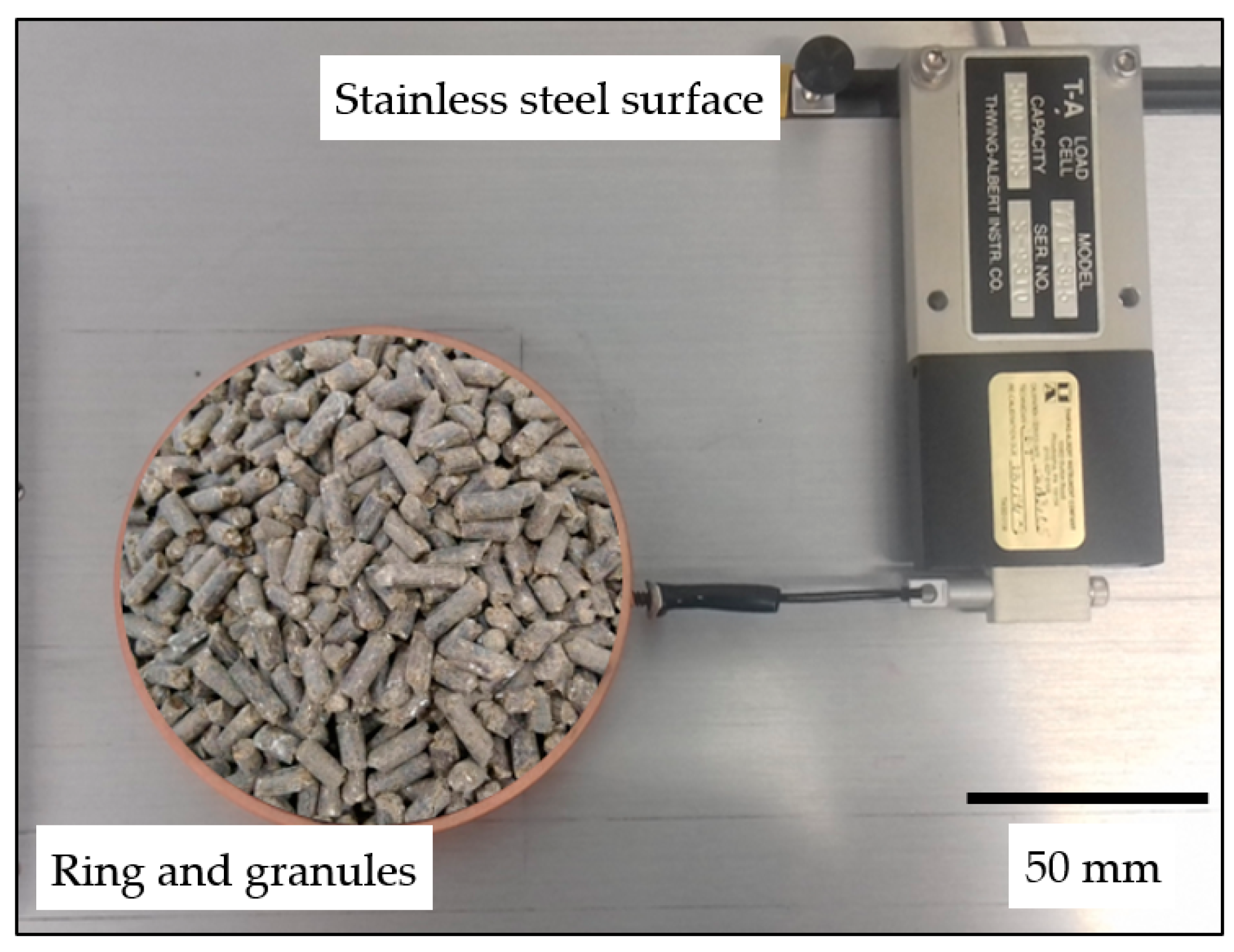
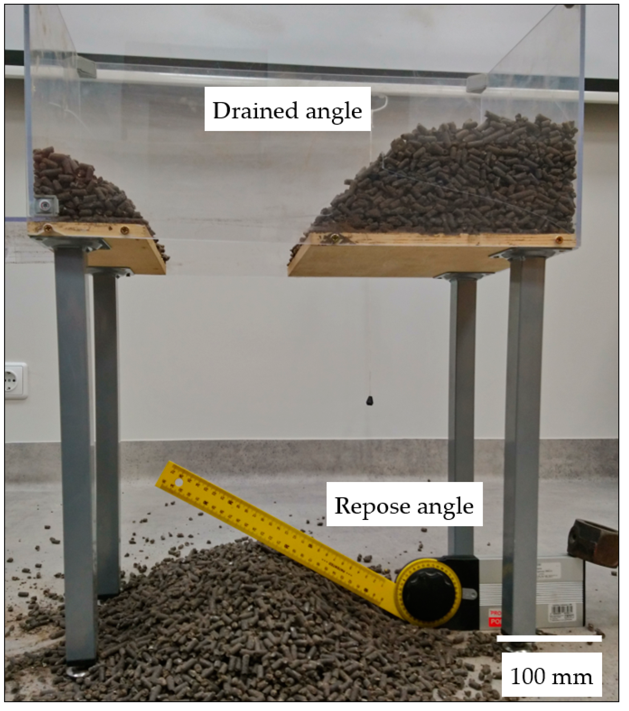
2.1. Properties of Granular Fertilizers
2.2. Verification of Granular Properties and Spreading Modeling Using Discrete Element Method
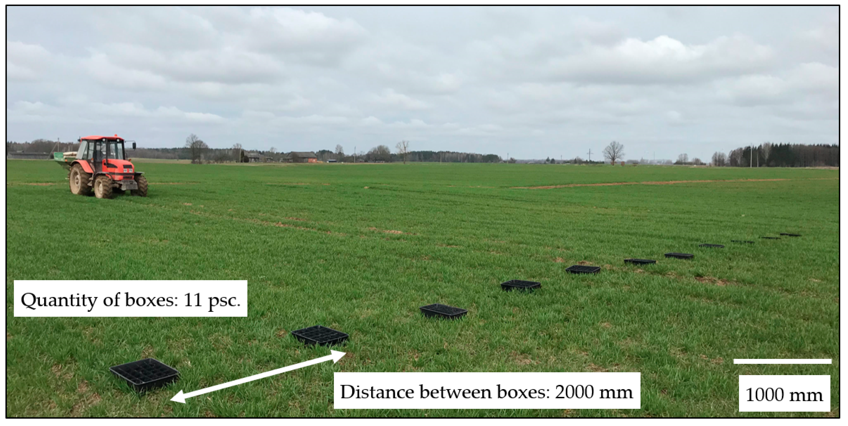
2.3. Experimental Spread of Fertilizer under Field Conditions
3. Results and Discussion
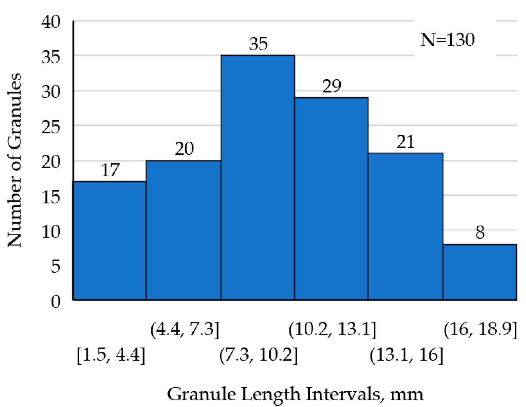
3.1. Properties of Granular Fertilizers
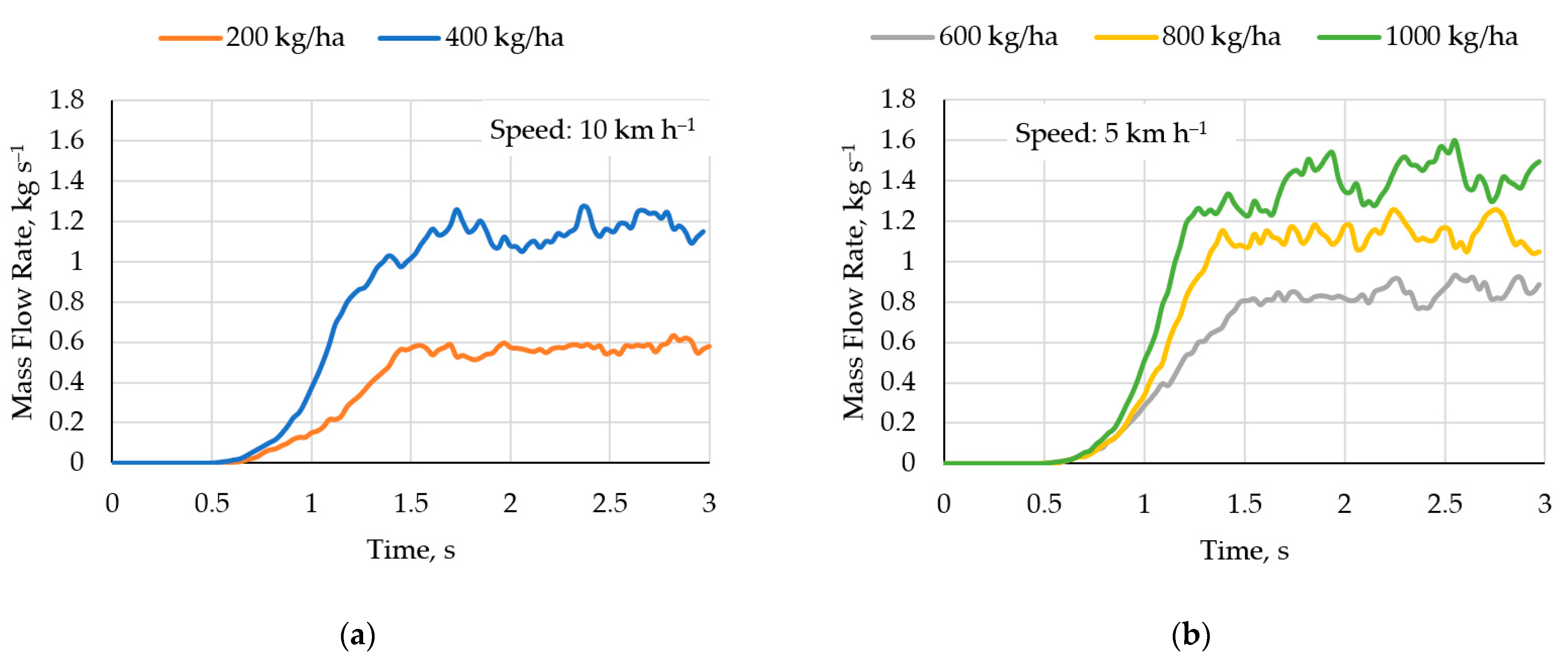
3.2. Verification of Granular Fertilizer Properties and Their Falling through the Bunker Shutter
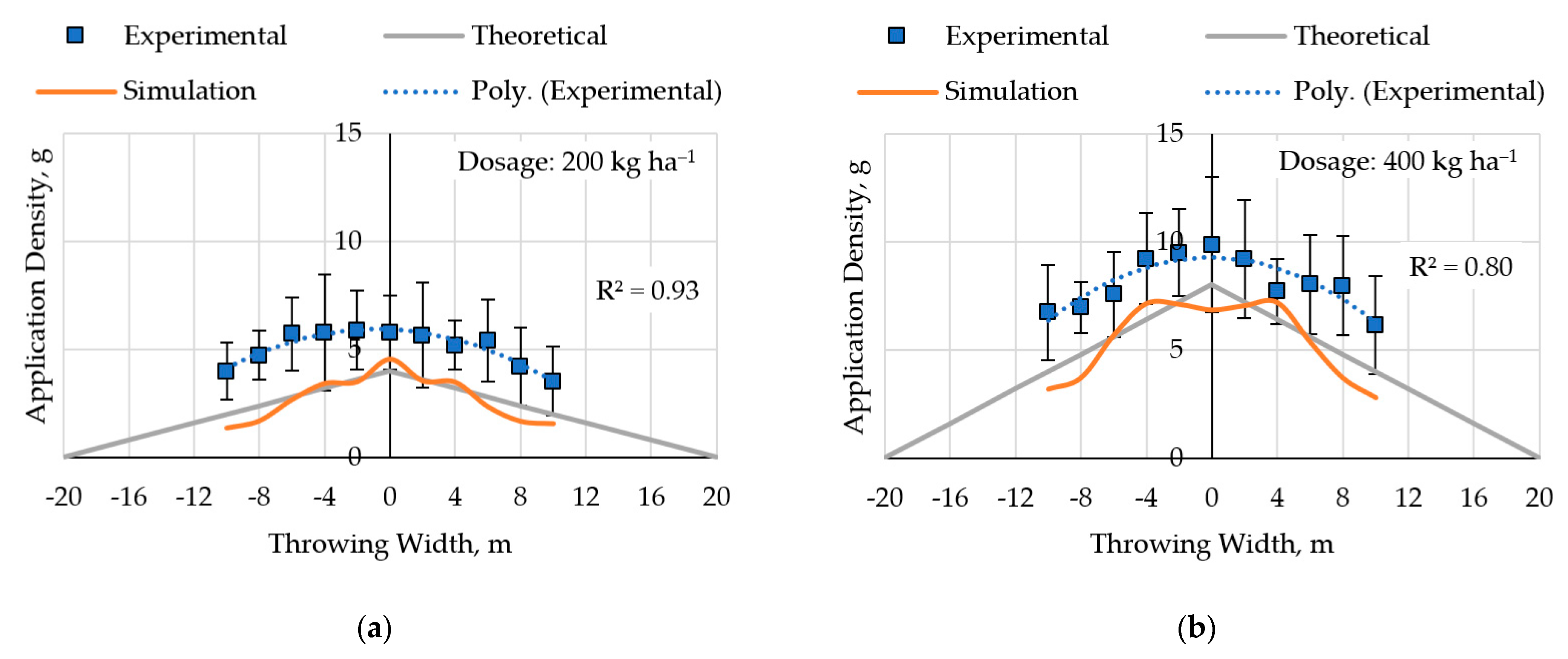
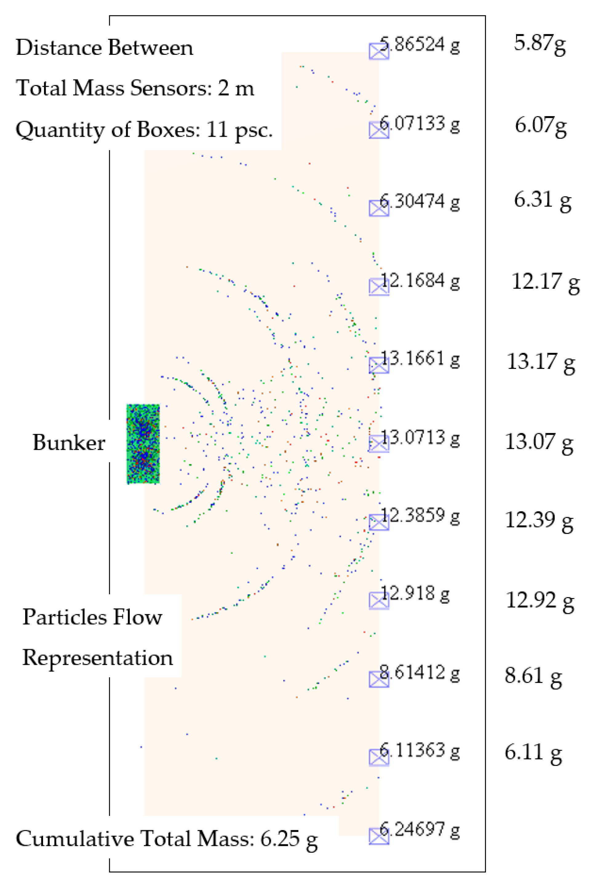
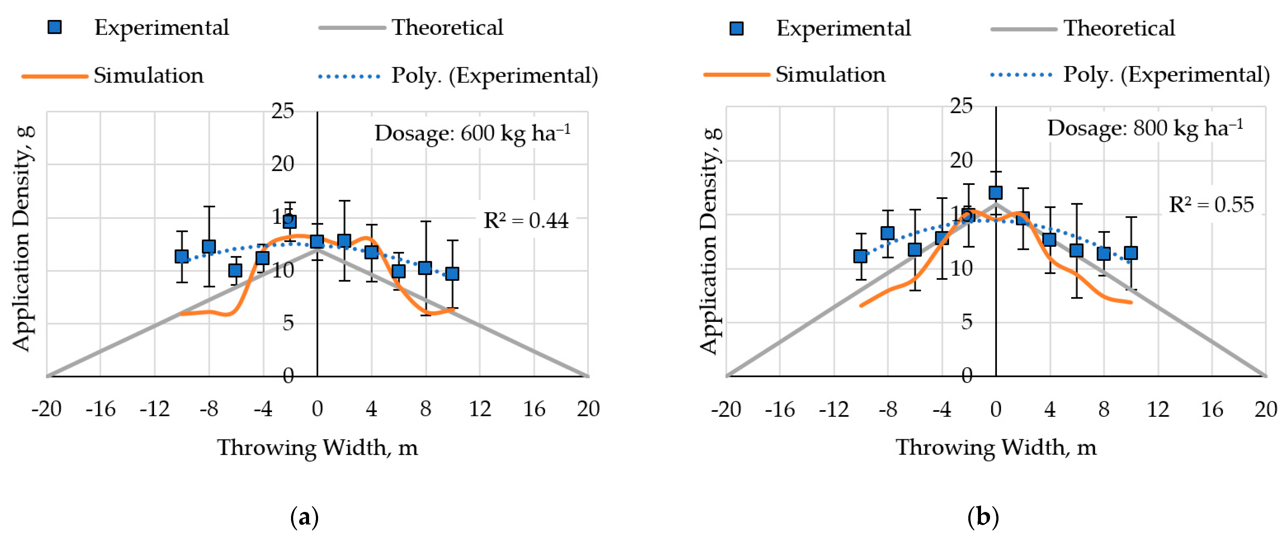
3.3. Experiment under Field Conditions and Simulation Spread of Fertilizer
4. Conclusions
Author Contributions
Funding
Institutional Review Board Statement
Informed Consent Statement
Data Availability Statement
Acknowledgments
Conflicts of Interest
References
- Rutkoviene, V.; Cesoniene, L.; Steponavicius, D. Nitrogen Losses from Organic and Mineral Fertilizers in Model Soil System. Cereal Res. Commun. 2007, 35, 313–316. [Google Scholar] [CrossRef]
- Raee, R.; Akbarpour, V.; Bahmanyar, M.A. Morphological Attributes and Phytochemical Compounds of Satureja hortensis L. in Response to Poultry Pellet and Zinc Sulphate Applications. J. Hortic. Sci. 2023, 36, 763–776. [Google Scholar] [CrossRef]
- Kaiser, D.E.; Mallarino, A.P.; Sawyer, J.E. Utilization of Poultry Manure Phosphorus for Corn Production. Soil Sci. Soc. Am. J. 2010, 74, 2211–2222. [Google Scholar] [CrossRef]
- Schroeder, P.D.; Radcliffe, D.E.; Cabrera, M.L. Rainfall Timing and Poultry Litter Application Rate Effects on Phosphorus Loss in Surface Runoff. J. Environ. Qual. 2004, 33, 2201–2209. [Google Scholar] [CrossRef]
- Abdala, D.B.; Ghosh, A.K.; da Silva, I.R.; de Novais, R.F.; Alvarez Venegas, V.H. Phosphorus Saturation of a Tropical Soil and Related P Leaching Caused by Poultry Litter Addition. Agric. Ecosyst. Environ. 2012, 162, 15–23. [Google Scholar] [CrossRef]
- Alloway, B.J. Sources of Heavy Metals and Metalloids in Soils. In Heavy Metals in Soils; Alloway, B., Ed.; Environmental Pollution; Springer: Dordrecht, The Netherlands, 2013; Volume 22, pp. 11–50. [Google Scholar] [CrossRef]
- Xiaobing, W.A.N.G.; Wuxing, L.I.U.; Zhengao, L.I.; Ying, T.E.N.G.; Christie, P.; Yongming, L.U.O. Effects of Long-Term Fertilizer Applications on Peanut Yield and Quality and Plant and Soil Heavy Metal Accumulation. Pedosphere 2020, 30, 555–562. [Google Scholar] [CrossRef]
- Jalali, M.; Hurseresht, Z. Assessment of Mobile and Potential Mobile Trace Elements Extractability in Calcareous Soils Using Different Extracting Agents. Front. Environ. Sci. Eng. 2020, 14, 7. [Google Scholar] [CrossRef]
- Jotautiene, E.; Bivainis, V.; Mieldazys, R.; Gaudutis, A.; Jasinskas, A. Experimental and Numerical Research of Granular Manure Fertilizer Application by Centrifugal Fertilizer Spreading. In Proceedings of the 21st International Scientific Conference “Engineering for Rural Development”, Jelgava, Latvia, 25–27 May 2022. [Google Scholar]
- Jasinskas, A.; Pekarskas, J.; Kucinskas, V.; Aboltins, A. Investigation of Natural Magnesium Mineral Fertilizer Granulation and Determination of Granule Qualitative Indicators. In Proceedings of the 15th Internal Scientific Conference “Engineering for Rural Development”, Jelgava, Latvia, 25–27 May 2016. [Google Scholar]
- Asgedom, H.; Tenuta, M.; Flaten, D.N.; Gao, X.; Kebreab, E. Nitrous Oxide Emissions from a Clay Soil Receiving Granular Urea Formulations and Dairy Manure. Agron. J. 2014, 106, 732–744. [Google Scholar] [CrossRef]
- Sulky Product List. Available online: http://www.sulky-burel.com/products (accessed on 6 April 2022).
- Søgaard, H.T.; Kierkegaard, P. Yield Reduction Resulting from Uneven Fertilizer Distribution. Trans. ASAE 1994, 37, 1749–1752. [Google Scholar] [CrossRef]
- Pocius, A.; Jotautiene, E.; Pekarskas, J.; Mieldazys, R.; Jasinskas, A. Research of Particle Geometrical Parameters and Aerodynamic Features of Granular Organic Compost Fertilizers. In Proceedings of the 13th International Scientific Conference “Engineering for Rural Development”, Jelgava, Latvia, 20–29 May 2014. [Google Scholar]
- Zinkevičienė, R.; Jotautienė, E.; Juostas, A.; Comparetti, A.; Vaiciukevičius, E. Simulation of Granular Organic Fertilizer Application by Centrifugal Spreader. Agronomy 2021, 11, 247. [Google Scholar] [CrossRef]
- Van Liedekerke, P.; Piron, E.; Vangeyte, J.; Villette, S.; Ramon, H.; Tijskens, E. Recent Results of Experimentation and DEM Modeling of Centrifugal Fertilizer Spreading. Granul. Matter 2008, 10, 247–255. [Google Scholar] [CrossRef]
- Zinkevičienė, R.; Jotautienė, E.; Jasinskas, A.; Kriaučiūnienė, Z.; Lekavičienė, K.; Naujokienė, V.; Šarauskis, E. Determination of Properties of Loose and Granulated Organic Fertilizers and Qualitative Assessment of Fertilizer Spreading. Sustainability 2022, 14, 4355. [Google Scholar] [CrossRef]
- Gavrilović, M.; Dimitrijević, A.; Radojičin, M.; Mileusnić, Z.; Miodragović, R. Effects of the Application System on the Physical and Mechanical Properties of Mineral Fertilizers. J. Process. Energy Agric. 2018, 22, 180–183. [Google Scholar] [CrossRef]
- Koko, J.; Virin, T. Optimization of a Fertilizer Spreading Process. Math. Comput. Simul. 2009, 79, 3099–3109. [Google Scholar] [CrossRef]
- Olieslagers, R.; Ramon, H.; De Baerdemaeker, J. Calculation of Fertilizer Distribution Patterns from a Spinning Disc Spreader by Means of a Simulation Model. J. Agric. Eng. Res. 1996, 63, 137–152. [Google Scholar] [CrossRef]
- Bivainis, V.; Jotautiene, E.; Zinkeviciene, R. Assessment of Granulated Manure Fertilizer Centrifugal Spreading Field Simulation. In Proceedings of the 20th International Conference “Engineering for Rural Development”, Jelgava, Latvia, 26–28 May 2021. [Google Scholar]
- Van Liedekerke, P.; Tijskens, E.; Dintwa, E.; Rioual, F.; Vangeyte, J.; Ramon, H. DEM Simulations of the Particle Flow on a Centrifugal Fertilizer Spreader. Powder Technol. 2009, 190, 348–360. [Google Scholar] [CrossRef]
- Organic Fertilizer ORGEVIT 4-3-2.5 Datasheet. Available online: https://memon.nl/products/orgevit-4-3-2-5/ (accessed on 10 March 2023).
- Ding, S.; Bai, L.; Yao, Y.; Yue, B.; Fu, Z.; Zheng, Z.; Huang, Y. Discrete Element Modelling (DEM) of Fertilizer Dual-Banding with Adjustable Rates. Comput. Electron. Agric. 2018, 152, 32–39. [Google Scholar] [CrossRef]
- Gallego, E.; Fuentes, J.M.; Ruiz, Á.; Hernández-Rodrigo, G.; Aguado, P.; Ayuga, F. Determination of Mechanical Properties for Wood Pellets Used in DEM Simulations. Int. Agrophys. 2020, 34, 485–494. [Google Scholar] [CrossRef]
- Yinyan, S.; Man, C.; Xiaochan, W.; Odhiambo, M.O.; Weimin, D. Numerical Simulation of Spreading Performance and Distribution Pattern of Centrifugal Variable-Rate Fertilizer Applicator Based on DEM Software. Comput. Electron. Agric. 2018, 144, 249–259. [Google Scholar] [CrossRef]
- Yang, L.; Chen, L.; Zhang, J.; Liu, H.; Sun, Z.; Sun, H.; Zheng, L. Fertilizer Sowing Simulation of a Variable-Rate Fertilizer Applicator Based on EDEM. In Proceedings of the 6th International “IFAC Conference on Bio-Robotics”, Beijing, China, 13–15 July 2018. [Google Scholar]
- Coetzee, C.J.; Lombard, S.G. Discrete Element Method Modelling of a Centrifugal Fertiliser Spreader. Biosyst. Eng. 2011, 109, 308–325. [Google Scholar] [CrossRef]
- Van Liedekerke, P.; Tijskens, E.; Ramon, H. Discrete Element Simulations of the Influence of Fertiliser Physical Properties on the Spread Pattern from Spinning Disc Spreaders. Biosyst. Eng. 2009, 102, 392–405. [Google Scholar] [CrossRef]
- Liping, Z.; Weiqiang, Z.; Lixin, Z.; Yulong, L. Design of a Sieve Bucket Spreading Mechanism Based on EDEM. J. Eng. Sci. Technol. Rev. 2019, 12, 84–90. [Google Scholar]
- Organic Fertilizer BENESOL 4-3-3 Datasheet. Available online: https://benefert.com/products/solid-organic-fertilizers/organic-fertilizer-benesol-4-3-3/ (accessed on 15 February 2023).
- Tang, P.; Li, H.; Issaka, Z.; Chen, C. Effect of manifold layout and fertilizer solution concentration on fertilization and flushing times and uniformity of drip irrigation systems. Agric. Water Manag. 2018, 200, 71–79. [Google Scholar] [CrossRef]
- Reumers, J.; Tijskens, E.; Ramon, H. Experimental characterisation of the tangential and cylindrical fertiliser distribution pattern from a spinning disc: A parameter study. Biosyst. Eng. 2003, 86, 327–337. [Google Scholar] [CrossRef]
- El-Emam, M.A.; Zhou, L.; Shi, W.D.; Sobhi, M. Determination of Some Engineering Properties of Jojoba Granular Matter [Simmondsia Chinensis]. Granul. Matter 2023, 25, 24. [Google Scholar] [CrossRef]
- Przywara, A.; Santoro, F.; Kraszkiewicz, A.; Pecyna, A.; Pascuzzi, S. Experimental study of disc fertilizer spreader performance. Agriculture 2020, 10, 467. [Google Scholar] [CrossRef]


| Indicators | Values |
|---|---|
| Nitrogen (N) total, % | 4.0 |
| Nitrogen (N) organic, % | 3.6 |
| Ammonia (NH4), % | 0.4 |
| Water-soluble phosphorus pentoxide (P2O5), % | 3.0 |
| Water-soluble potassium oxide (K2O), % | 2.5 |
| Calcium oxide (CaO), % | 9.0 |
| Magnesium oxide (MgO), % | 1.0 |
| Sulphur (SO3), % | 1.5 |
| Granule diameter, mm | 5.49 ± 0.12 * |
| Granule length, mm | 9.60 ± 0.74 * |
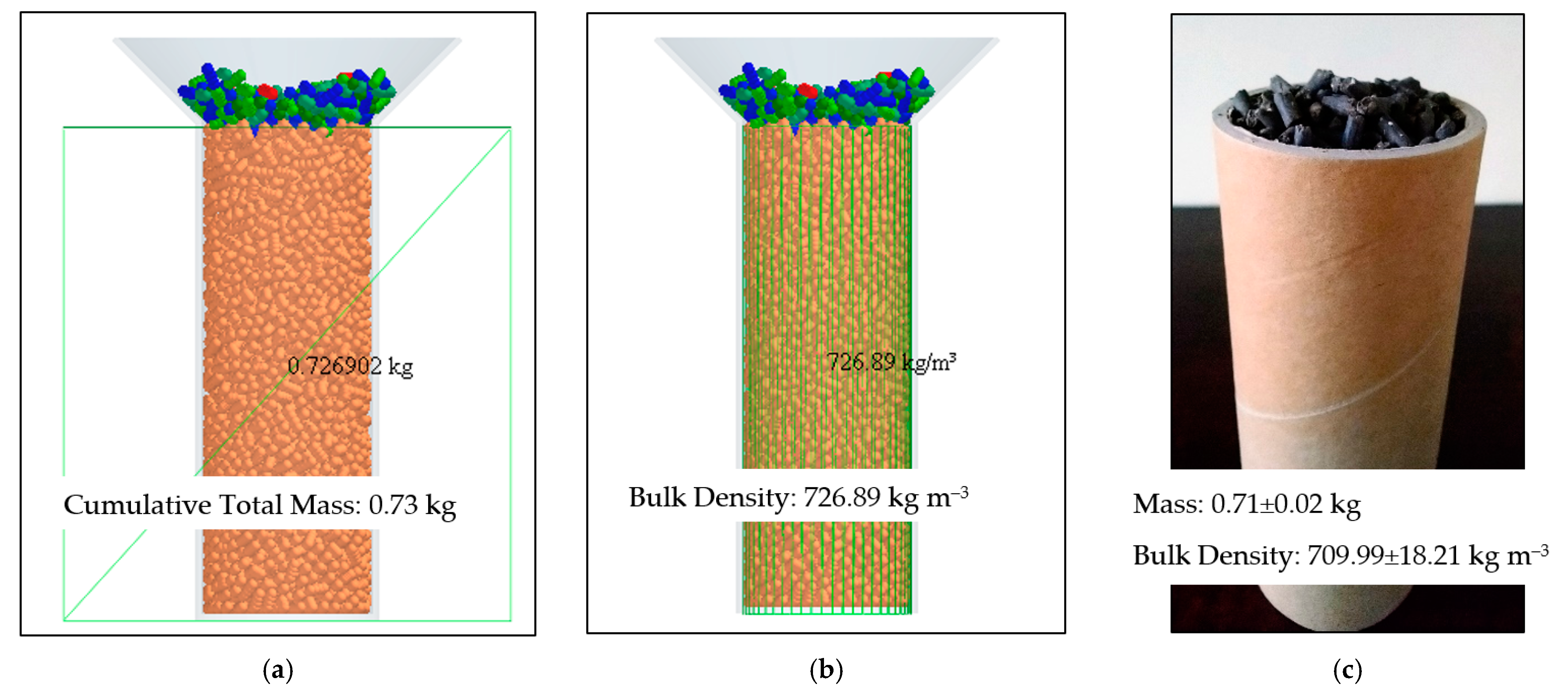
| Granule bulk density, kg m−3 | 709.99 ± 21 * |
| Granule solid density, kg m−3 | 1297.21 ± 36 * |
| Indicators | Values | Values Variation Range in Verification |
|---|---|---|
| Young’s Modulus, MPa | 75 | - |
| Poisson’s Ratio | 0.25 | - |
| Coefficient of Restitution (Particle–Equipment Material) | 0.45 | 0.35 ÷ 0.55 |
| Coefficient of Restitution (Particle–Particle) | 0.60 | 0.50 ÷ 0.70 |
| Coefficient of Static Friction (Particle–Particle) | 0.50 | 0.40 ÷ 0.60 |
| Coefficient of Kinetic Friction (Particle–Particle) | 0.25 | 0.15 ÷ 0.35 |
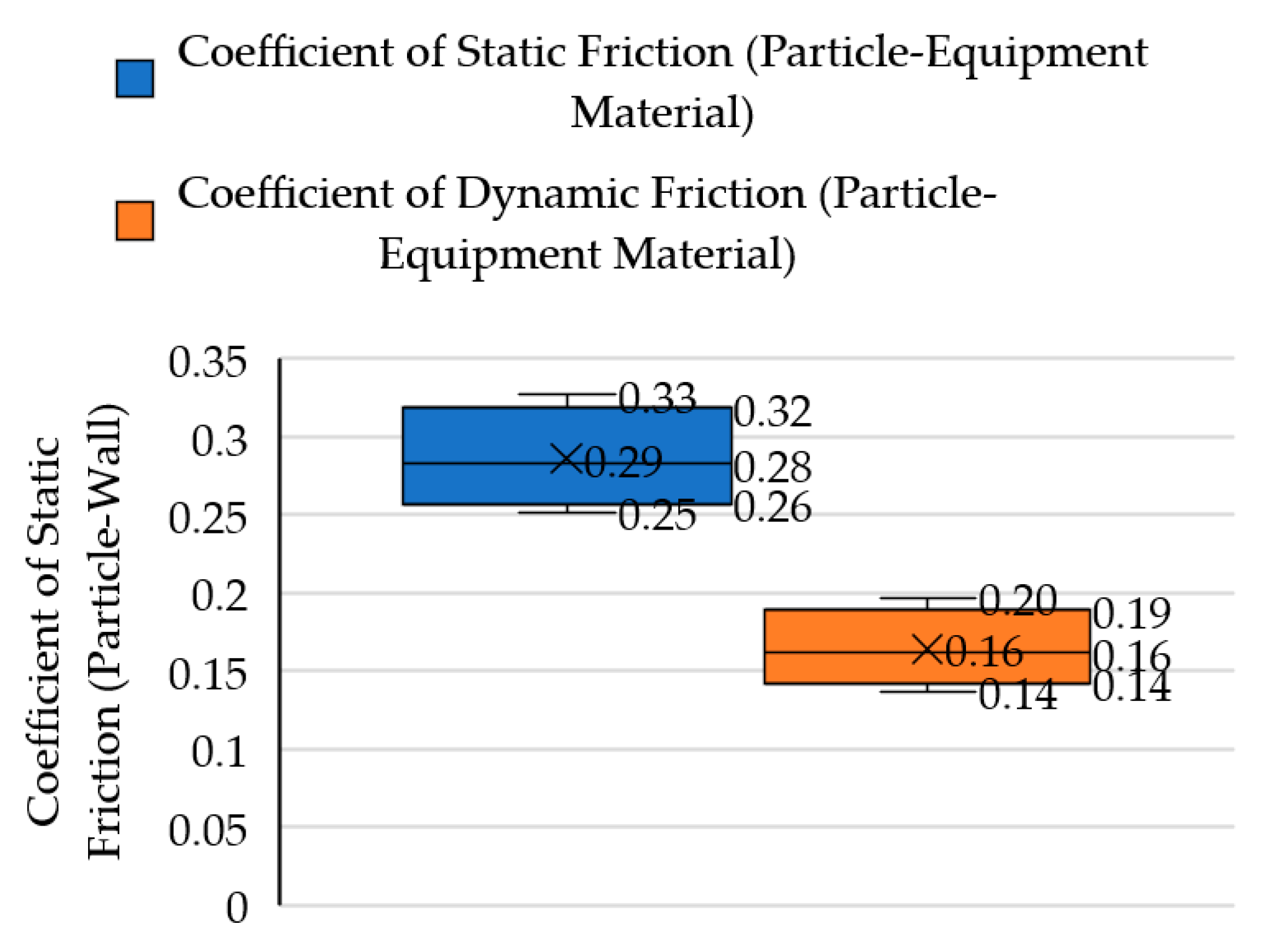
| Coefficient of Static Friction (Particle–Equipment Material) | 0.29 ± 0.03 * | - |
| Coefficient of Kinetic Friction (Particle–Equipment Material) | 0.16 ± 0.02 * | - |
| Indicators | Technical Parameters | |
|---|---|---|
| Spreader model | Amazone ZA-M-1001 | Amazone ZA-M-1201 |
| Spreading dosage norm, kg ha−1 | 200 and 400 | 600, 800 and 1000 |
| Speed, km h−1 | 10 | 5 |
| Spreading disk OM 18–24 diameter, mm | 455 | 455 |
| Length of the vanes, mm | 260 (short); 360 (long) | 260 (short); 360 (long) |
| Vane setting positions | 15 (short); 43 (long) | 15 (short); 43 (long) |
| Disk speed, min−1 | 720 | 720 |
| Working width, m | 20 | 20 |
| Throwing width, m | 40 | 40 |
 |  |  |  | 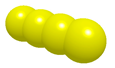 | 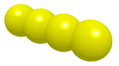 | |
|---|---|---|---|---|---|---|
| Shape | Single Sphere | Dual Sphere | Straight Four Sphere | |||
| Length, mm | 2.95 | 5.85 | 8.75 | 11.65 | 14.55 | 17.45 |
| Proportion, % | 13 | 15 | 27 | 22 | 16 | 6 |
| Spreading Dosage Norm, kg ha−1 | Theoretical Fertilizer Mass Flow of One Bunker Shutter, kg s−1 | Fertilizer Mass Flow Obtained during the Calibration of One Bunker Shutter, kg s−1 | Fertilizer Flow Obtained during the Simulation, kg s−1 | Simulation Results vs. Experimental Results, % | Speed, km h−1 | Spreader Model |
|---|---|---|---|---|---|---|
| 200 | 0.56 | 0.57 ± 0.10 * | 0.57 | −0.54 | 10 | Amazone ZA-M-1001 |
| 400 | 1.11 | 1.18 ± 0.17 * | 1.16 | −1.90 | ||
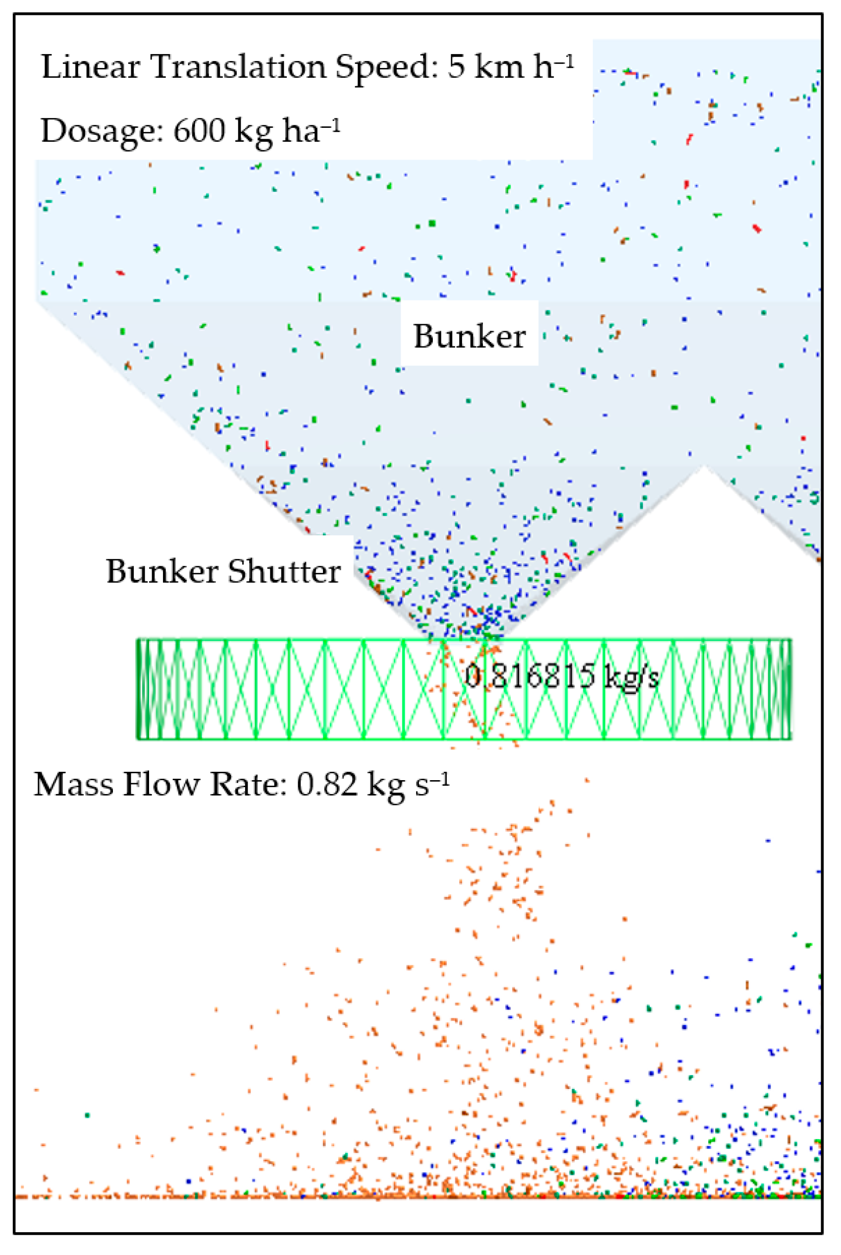
| 600 | 0.83 | 0.80 ± 0.12 * | 0.84 | +5.10 | 5 | Amazone ZA-M-1201 |
| 800 | 1.11 | 1.17 ± 0.11 * | 1.13 | −2.98 | ||
| 1000 | 1.39 | 1.28 ± 0.24 * | 1.42 | +9.87 |
Disclaimer/Publisher’s Note: The statements, opinions and data contained in all publications are solely those of the individual author(s) and contributor(s) and not of MDPI and/or the editor(s). MDPI and/or the editor(s) disclaim responsibility for any injury to people or property resulting from any ideas, methods, instructions or products referred to in the content. |
© 2023 by the authors. Licensee MDPI, Basel, Switzerland. This article is an open access article distributed under the terms and conditions of the Creative Commons Attribution (CC BY) license (https://creativecommons.org/licenses/by/4.0/).
Share and Cite
Bivainis, V.; Jotautienė, E.; Lekavičienė, K.; Mieldažys, R.; Juodišius, G. Theoretical and Experimental Verification of Organic Granular Fertilizer Spreading. Agriculture 2023, 13, 1135. https://doi.org/10.3390/agriculture13061135
Bivainis V, Jotautienė E, Lekavičienė K, Mieldažys R, Juodišius G. Theoretical and Experimental Verification of Organic Granular Fertilizer Spreading. Agriculture. 2023; 13(6):1135. https://doi.org/10.3390/agriculture13061135
Chicago/Turabian StyleBivainis, Vaidas, Eglė Jotautienė, Kristina Lekavičienė, Ramūnas Mieldažys, and Gražvydas Juodišius. 2023. "Theoretical and Experimental Verification of Organic Granular Fertilizer Spreading" Agriculture 13, no. 6: 1135. https://doi.org/10.3390/agriculture13061135