Article

Mechanism Analysis of the Influence of Structural Parameters on the Hydraulic Performance of the Novel Y-Shaped Emitter

College of Water Resources Science and Engineering, Taiyuan University of Technology, Taiyuan 030024, China
*
Author to whom correspondence should be addressed.
Agriculture 2023, 13(6), 1160; https://doi.org/10.3390/agriculture13061160
Submission received: 23 April 2023 / Revised: 24 May 2023 / Accepted: 29 May 2023 / Published: 30 May 2023

Abstract

:
As a key component of a drip irrigation system, the performance of drip irrigation emitters is determined by the flow channel structures and parameters. In this paper, a novel Y-shaped labyrinth-channel emitter was proposed, and the influence of the hydraulic performance was researched under different waist-arc angles (α) and ratios of crown height to chord length (a:b). The flow characteristics and energy dissipation mechanisms of water in the emitter were analyzed by using fluid dynamics software. The analysis showed that, keeping the ratio of crown height to chord length unchanged and with an increase in the waist-arc angle from 90° to 180°, the pressure-drop ratio before and after the water flow through the vortex area increased, and the hydraulic performance of the emitter was improved, specifically: the design flow could be reduced by 6.02–26.7%, and the slope of the curve could be reduced by 9.83–28.1%. The smaller the ratio of crown height to chord length, the weaker the influence of waist-arc angle was on the design flow and hydraulic performance. Keeping the waist-arc angle unchanged, there was a decrease in the ratio of crown height to chord length from 6:30 to 1:30, the vortex strength inside the emitter channel increased, and the hydraulic performance was improved: the design flow could be reduced by 7.56–23.5%, and the slope of the curve could be reduced by 5.43–20.5%. The bigger the waist-arc angle, the weaker the influence of the ratio of crown height to chord length was on the design flow and the hydraulic performance, even to the point of having no effect. When the Y-shaped emitter was close to the pressure-flow curve slope of the commonly-used triangular-channel emitter, the hydraulic performance of the two was similar, and the former could increase the channel width by 25%, as compared to the latter, or shorten the channel length by 44.3%. The results showed that the Y-shaped emitter had better hydraulic performance compared with the triangular-flow-channel emitter commonly used today. Therefore, the Y-shaped emitter has broad application prospects in water-saving irrigation.

1. Introduction

As a large agricultural country, China’s agricultural irrigation water accounts for 57% of the total national water consumption, and the effective utilization coefficient of agricultural irrigation water is only 0.565, which is far below the level of the leading nations. Among them, Israel is as high as 0.87, while Australia and Russia are around 0.8 [1]. Therefore, it is imperative to optimize the use of modern water-saving irrigation technology.
Water-saving irrigation technology can effectively improve the water utilization coefficient, where the minimum water utilization coefficient is 0.80 for pipeline irrigation technology and sprinkler irrigation technology, 0.85 for micro-irrigation technology, and 0.90 for drip irrigation technology [2]. Drip irrigation technology is the most widely used water-saving irrigation method [3]. In addition to effective water saving, it can also be applied, in conjunction with water and fertilizer, to achieve increased yield and efficiency [4]. Therefore, it is known as the “No. 1 technology” of modern agriculture.
The emitter is the key component in a drip irrigation system [5], and its performance directly affects the reliability of a drip irrigation system and the irrigation quality. As compared to other forms of channels, the labyrinth-channel emitter had the advantages of stable outflow, uniform irrigation and good irrigation quality [6]. Therefore, the development and design of novel labyrinth-channel emitters that can improve the efficiency of water conservation is of great significance for the development of water-saving agriculture.
The design flow, the pressure-flow curve slope of the emitter and the energy loss in the channel reflect the hydraulic performance of the emitter. The pressure-flow relationship is expressed as follows:
q = k h x
where q is the emitter outlet flow, L/h; k is the flow coefficient; x is the flow state index; h is the inlet pressure of the emitter, mH2O. The smaller the slope of the pressure-flow curve (the weaker the sensitivity of the flow to pressure), and the smaller the same inlet pressure out of the flow, the greater the energy loss of water flow per unit length of the channel, leading to the improved hydraulic performance of the emitter.
Computational fluid dynamics is a powerful tool for analyzing fluid flow. It has become an indispensable part of emitter design with its own characteristics and unique features, when combined with theoretical analysis and experimental studies. Many scholars have carried out in-depth research on labyrinth-channel emitters by using Computational Fluid Dynamics (CFD). Wei et al. [7] used CFD to simulate the outflow of three channels under different pressures, and verified the correctness of the results with measured data. Zhou et al. [8] used a CFD software package to analyze the influence of structural parameters on the hydraulic performance of microporous ceramic emitters. Baghel et al. [9] used the standard k-ε model to analyze the flow characteristics of emitters with four different channels. The results showed that the water energy dissipation per unit length of the triangular channel was larger than that of the rectangular, trapezoidal, and circular channels. Zanca et al. [10] used CFD software to optimize the dripper structure and investigated the mechanism of droplet formation at the exit of the drip head.
The reasonable selection of the form and the parameters of the channel structure could effectively improve the hydraulic performance of the emitter [11]. Saccone et al. [12] studied seven different toothed flow channel emitters and analyzed the relationship between channel cross-section and hydraulic performance. Zhang et al. [13] found that the flow of a toothed labyrinth-channel emitter increased with an increase in the tooth angle, and an ortho-tooth-type emitter with a tooth angle of 70° had the best hydraulic performance. Celik et al. [14] conducted experimental and CFD analysis of the flow characteristics of labyrinth-channel emitters and found that the channel’s corner structure could improve the hydraulic performance of the emitter. Du et al. [15] found that changing the flow path of the emitter from one inlet and one outlet to one inlet and two outlets resulted in better hydraulic performance. Patil et al. [16] studied labyrinth emitters with five different tooth shapes and found that the tooth structure has a greater effect on the vortex in the flow field, and pointed out that a reasonable boundary structure can increase the energy dissipation in the channel. Wang et al. [17] changed the channel structure of the emitter by adding internal teeth into the channel to increase the number and the strength of the vortices in the flow field, which in turn led to the improved hydraulic performance of the emitter. Feng et al. [18] found that the elimination of the vortex zone in the channel reduced the hydraulic performance of the emitter. Wu et al. [19] used a tapered surge-expansion structure to increase the local head loss of water flow in the emitter channel. Guo et al. [20] designed a two-way hedge-channel emitter to increase the energy dissipation effect in water-hedge mixing, which improves the hydraulic performance of the emitter. Xing [21] optimized the flow ratio by enlarging the upper perforated inlet in the perforated drip irrigation channel to improve its hydraulic performance. Zhu et al. [22] incorporated a spiral manifold into an inserted-rod emitter to enhance the turbulence of the water flow inside the channel, which provided a reference for the optimization of the hydraulic characteristics of the emitter. Li et al. [23] proposed a circular water-retaining labyrinth-channel emitter and found that the larger the proportion of the low-speed vortex zone, the more obvious the energy dissipation, and increased the proportion of the low-speed vortex zone by improving the structure to square and star-shaped. However, most studies have focused on the relationship between the structural parameters and the hydraulic performance using conventional channels. Although several new labyrinth channels have been designed and constructed, a mechanistic analysis of the effect of the channel structure on the hydraulic performance of emitters has been neglected.
Based on the above idea that changes in the structure and the parameters of the channel could improve the hydraulic performance of an emitter, we designed a novel Y-shaped labyrinth-channel structure. As the emitter has good hydraulic performance, the premise is of studying the anti-clogging performance (no matter how good the anti-clogging performance of an emitter is, if its hydraulic performance is poor, this emitter is not suitable for practical work), so the purposes of the current research phase were the following: to increase the bending degree of the water flow in a channel by changing the waist-arc angle and the ratio of crown height to chord length, in order to enhance hydraulic performance; to analyze the internal energy dissipation mechanism; based on the Y-shaped emitter with superior hydraulic performance, to appropriately increase the channel width or shorten the channel length to take into account the hydraulic performance and anti-clogging performance of the emitter; and to provide a reference for the further development of high-performance emitters.

2. Materials and Methods

2.1. Emitter Design and Size Parameters

Studies had shown that the head loss of water flow in the labyrinth channel is dominated by local head loss [24]; a vortex can enhance the degree of energy dissipation of water flow. For this purpose, we associated the water flow through a short distance many times with a large angle of deflection, impact on the side wall, a fully developed vortex and other effects to increase local head loss of water flow and dissipate energy, and then designed a new Y-shaped channel emitter (a channel with Y-shaped water retaining parts).
The size of most emitter channels was 0.5–1.2 mm, and channels smaller than 0.7 mm were prone to clogging [25]. This paper referenced the size of a labyrinth emitter used in a side-type drip irrigation belt manufactured by Xinjiang Tianye Group (Shihezi, China), and the channel depth was 1 mm, the minimum channel width (d) was 1 mm, the channel length (L) was about 300.0 mm, and the minimum width of the Y-teeth was 1 mm. The design was as follows: we made two sets of relative arcs with a radius of 1 mm (the two sets of arcs were 1 mm apart) as the waist boundary of the channel; made an arc from the upper apex of the inner arc to the middle and intersect as the Y-teeth crown; and drew the upper semicircle with the distance of the upper vertex of the outer arc of the waist as the diameter, and then we used a distance of 1 mm above the crown of Y-teeth as a horizontal straight line to intersect the upper semicircle, and used the lower part as the upper boundary of the channel. Upon comparing the slope of the pressure-flow curve, when the waist-arc angle of the Y-shaped emitter was larger than 90°, the ratio of crown height (a) to chord length (b) of the Y-teeth (hereinafter referred to as crown-to-chord ratio) was less than 6:30, the slope of the curve would be smaller than the currently used triangular-channel emitter (the hydraulic performance of triangular-channel emitters was better than rectangular channels and trapezoidal channels [7]). To ensure that the minimum width of the channel was not less than 1 mm, the waist-arc angle (α) of the Y-shaped emitter could not be greater than 180°. At the same time, we considered the integrity of the channel from these three aspects to determine the range of the waist-arc angle as 90–180°, and the crown-to-chord ratio (a:b) was at least 1:30.
The schematic diagram of the side-type drip irrigation belt arrangement is shown in Figure 1, and the emitter is installed on the capillary tube. In the diagram, C represents the inlet; D the outlet; E the last emitter outlet and the next emitter inlet, the distance between which in practice is usually set to 0. The distance between the two outlets can be regarded as the emitter spacing. Different spacing has an effect on the uniformity of irrigation throughout the drip irrigation belt, but has no effect on the hydraulic performance of individual emitters.
The channel schematic is shown in Figure 2. With an increase in the waist-arc angle, a decrease in the crown-to-chord ratio, and the influence of the channel structure, the concave-angle width (e) at the top of the Y-teeth increased slightly, and the concave-angle depth (n) was almost unchanged. The parameters of the Y-shaped emitter are shown in Table 1.

2.2. Control Equations

Fluent software based on computational fluid dynamics was used to numerically simulate the water flow of the emitter with different combinations of parameters, as shown in Table 1, and the pressure-flow relational curves and flow field diagrams were obtained for different sizes of emitters. Based on this information, the influence of the curve slope, the design flow of the emitter and the energy loss inside the channel on the hydraulic performance was analyzed.
Water flow movement inside the emitter was considered as viscous incompressible fluid movement. As this study focused on the hydraulic performance of the emitter at room temperature, the temperature field changes caused by the water-flow energy exchange, along with the mass force, were not considered, and the mass force was not considered. The control equations included the continuity equation and the Navier-Stokes equation.
Continuity equation:
u i x i = 0
Navier-Stokes equation:
d u i d t = 1 ρ p x i + μ 2 u i
where t is the time, s; ui is the flow velocity tensor; ρ is the density of water, kg/m3; μ is the dynamic viscosity coefficient; p is the fluid pressure, Pa; and xi is the coordinate tensor.
As previously demonstrated by researchers in [26], the standard k-ε turbulence model selected for the simulation of a labyrinth-channel emitter was more consistent with the actual situation, so this study selected a standard k-ε turbulence model. The equations of turbulent kinetic energy k and dissipation rate ε were as follows:
k equation:
ρ k t + ρ k u i x i = x j μ + μ t σ k k x j + G k ρ ε
ε equation:
ρ ε t + ρ ε u i x i = x j μ + μ t σ ε ε x j + C 1 ε ε k G k C 2 ε ρ ε 2 k
In addition:
G k = μ t u i x j + u j x i u i x j
μ t = ρ C μ k 2 ε
where: k is the turbulent energy; ε is the turbulent dissipation rate; μt is the turbulent viscosity; Gk is the production term of the turbulent energy k caused by the average velocity gradient; and empirical constants took the following values: C = 1.44, C = 1.92, Cμ = 0.09, σk = 1.0, σε = 1.3.

2.3. Mesh and Boundary Conditions

Using ICEM to establish a calculation model according to the actual size of the emitter, the repetitive nature of the emitter unit, and the pressure inlet decreases in a linear proportion, we used 5 units to simulate the water flow in the emitter channel. The results of this calculation were extrapolated to all units in the emitter channel. An unstructured grid was chosen as the computational grid [27]. In order to reduce the influence of the grid on the calculation results, the outflow of the emitter under inlet pressures of 5 m, 10 m, and 15 m, with the grid sizes of 0.13, 0.12, 0.11, 0.10, 0.08, and 0.07 mm, was calculated. When the grid size was 0.12 mm and 0.13 mm, the difference in the flow of the emitter was 0.37%, less than 0.5% [28], indicating that the grid size no longer affected the calculation result; therefore, we set the grid size at 0.12 mm. In addition, the grid at the side wall of the channel was set up according to the boundary layer. The thickness of the first boundary layer was 0.01 mm, and thereafter the layers increased by 1.5 times. The total number of layers was 6, and the total thickness of the boundary layer was 0.21 mm.
The calculation used an uncoupled implicit steady-state solver, and the inlet and outlet turbulence parameters were defined by the turbulence intensity, which was 5%. The inlet and outlet boundaries were set as pressure boundaries, where the inlet pressure was 5–15 mH2O and the outlet pressure was atmospheric pressure. The wall surface was a non-slip boundary, and for the flow of the wall area, a standard wall function was used, and the wall roughness was 0.01 mm. The numerical calculation used the finite volume method to disperse the control equations. The dispersion of the convection terms and other parameters were in a second-order, windward format; the coupling of velocity and pressure was solved by the SIMPLE algorithm; and the convergence accuracy was 10−4.

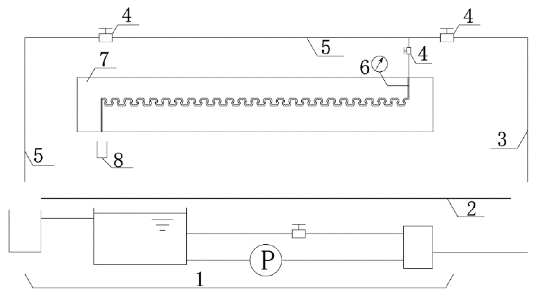
2.4. Validation of the Calculated Results

To further verify the correctness of the calculated results, physical model tests were conducted on the Y-shaped labyrinth-channel emitter. The minimum width of the physical model emitter channel was 1.2 mm, with a depth of 1.2 mm, and a length of 303.2 mm. The model is shown in Figure 3.
The test system included a water supply system; water transmission-and-return pipeline; test model; precision pressure gauge; etc. The schematic diagram is shown in Figure 4.
The physical quantities tested by the test were the inlet pressure and outflow of the emitter. The inlet pressure was measured within a maximum range of 0.40 Mpa with an accuracy of 0.25, according to the graded pressure gauge. The outflow was measured by measuring cylinders of different specifications according to its size.
The test was in accordance with the test specifications of the Micro-Emitter Irrigator-Dripper (SL/T67.1-94). Each inlet pressure was measured twice under the flow, and each flow measurement was at least 2 min. The difference between the two measured flows could not be more than 2% on average for the emitter’s outflow (L/h).
The results of the numerical simulation and physical model tests are shown in Table 2.
The relative errors between the simulated values and the measured results of the physical model validation performed in this study were 0.37–2.53%. This is due to the fact that during the experiment, the water temperature in the water transmission pipe would fluctuate by 1–2° and there would be a slight change in the viscosity of the water; this could have also been related to small deviations in the pressure applied in the experimental system, potentially resulting in errors in the physical experiments. On the other hand, when the simulations were performed, the simulated water had to be constant, which was difficult to achieve in practice; in general, the N-S and continuity equations used in the calculations had to be solved analytically with simple boundary conditions and omitting some minor factors. However, with the development of computational techniques, the numerical solutions of certain complex fluid motions have gradually improved.
From the data in Table 2, the significance level between the results of the numerical simulation and the physical model test was analyzed. We calculated the Root Mean Square Error (RMSE) as 0.088; the Nash Sutcliffe Efficiency (NSE) as 0.94; and the Coefficient of Determination (R2) as 0.99. We can see that [29] the value of RMSE is very small and the values of NSE and R2 are very close to 1, so the fitting effect of the two sets of data is good, indicating that the experimental operation, the mesh division and the selection of the computational model were reliable.

3. Calculation Results and Analysis

The flows of the water in the channels with 4 different waist-arc angles and 4 different crown-to-chord ratios in Table 1 were simulated at inlet pressures from 5 to 15 mH2O, and the pressure-flow relational curve and the flow-field diagram of the emitter, with different structural parameters, were obtained. According to the following:
q = k x h x 1
we calculated the slope of the pressure-flow relational curve for each emitter at different operating pressures.

3.1. Effect of Waist-Arc Angle and Crown-To-Chord Ratio on Hydraulic Performance

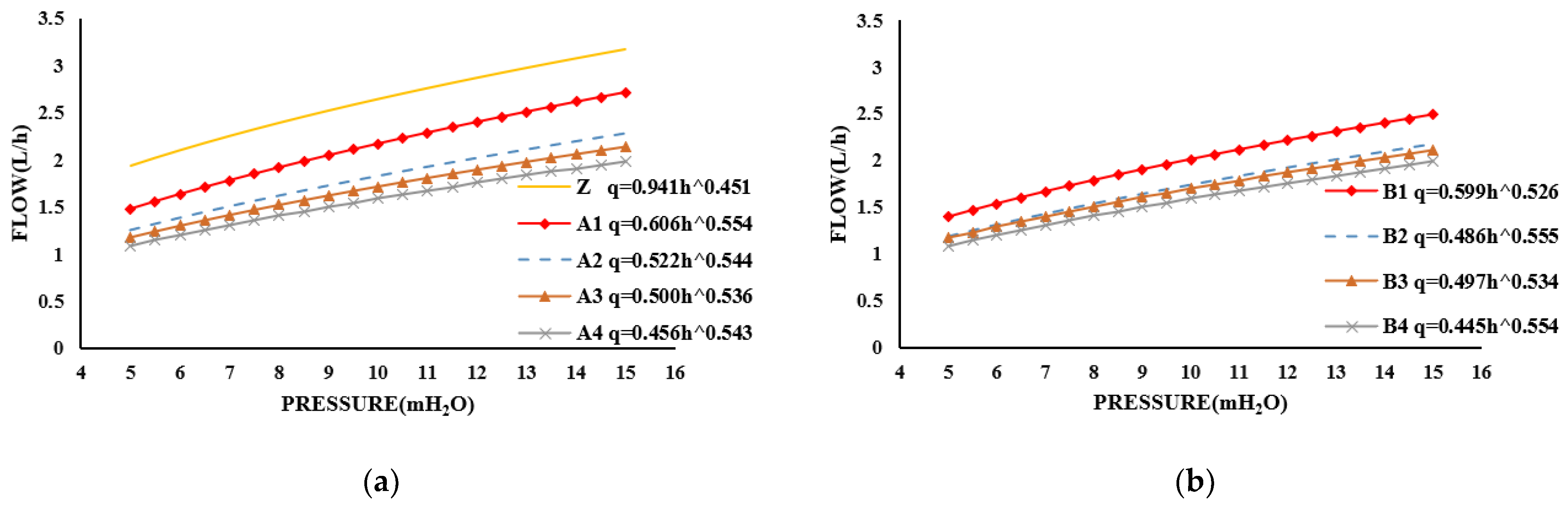
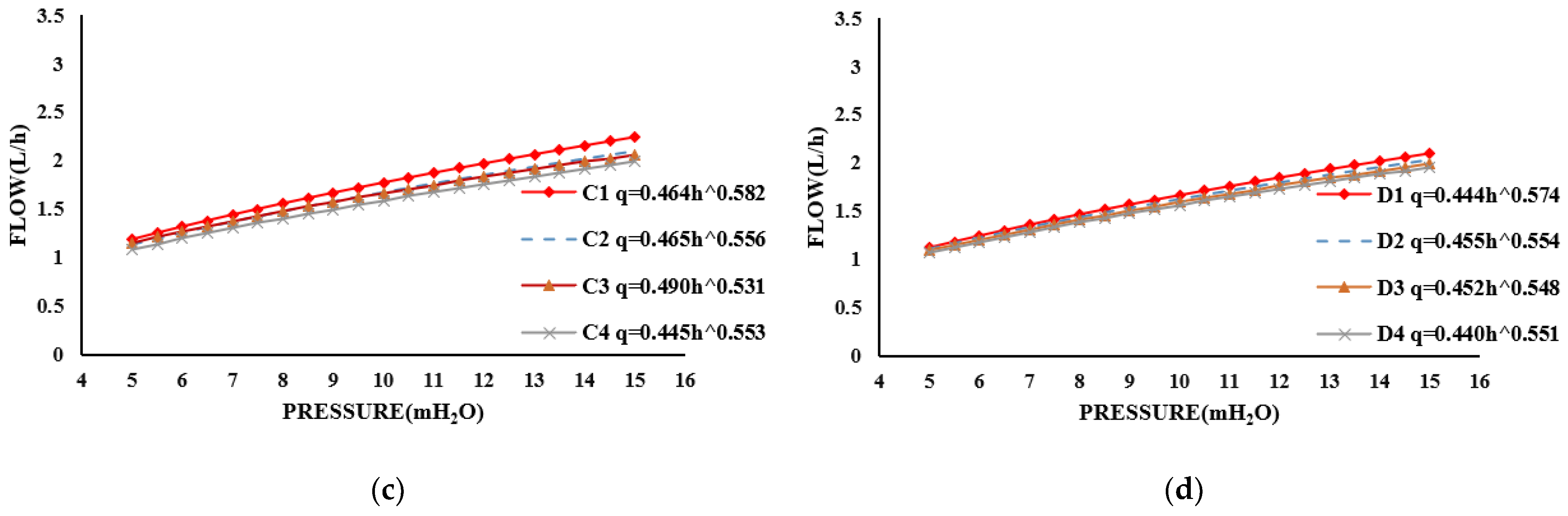
3.1.1. Analysis of the Influence of the Waist-Arc Angle on Hydraulic Performance

Assuming that the width and the depth of the channel had not changed and the length of the channel was approximately consistent, we investigated the effect of 4 waist-arc angles on the hydraulic performance of Y-shaped emitters at each crown-to-chord ratio, as shown in Table 1. A total of 16 Y-shaped emitter models was used, along with the commonly-used triangular-channel emitter (Z-type). Both emitters had the same section and channel length, and their pressure-flow curves are shown in Figure 5. Under an inlet pressure of 10 mH2O, the design flow and the curve slope of the emitter, with various parameters, are shown in Table 3.
It was observed in Table 3 that at 10 mH2O inlet pressure, the variations of the design flow and curve slope of the Y-shaped emitter were as follows:
When the crown-to-chord ratio remained unchanged at 6:30, for the A1-type emitter, as compared to the triangular-channel (Z-type) emitter, its design flow decreased by 18.1%, and the slope of the pressure-flow curve increased only by 0.84%. When the angle increased to 120°, 150°, and 180°, the design flow decreased by 16.1%, 20.7%, and 26.7%, and the slope of the curve decreased by 17.3%, 23.4%, and 28.1%, respectively, as compared to the 90° angle.
When the crown-to-chord ratio was 4:30, for every 30° increase in the waist-arc angle, the design flow decreased by 13.4%, 15.4% and 20.9%, respectively, and the slope of the curve decreased by 8.50%, 13.1% and 16.5%, respectively, as compared to 90°.
When the crown-to-chord ratio was 2:30, as compared to 90°, the design flow was reduced by 5.65%, 6.21%, and 10.2%, respectively, for every 30° increase in the waist-arc angle, and the slope of the curve was reduced by 9.80%, 12.3%, and 14.7%, respectively.
When the crown-to-chord ratio remained unchanged at 1:30, and the waist-arc angle also increased from 90° to 180°, for each 30° increase the design flow and curve slope decreased by 1.81% and 8.68%, 4.22% and 8.89%, and 6.02% and 9.83%, respectively, as compared to 90°.
The continuous decrease in the design flow and curve slope indicated that the sensitivity of the flow to pressure continued to decrease, and it is concluded that when the crown-to-chord ratio remained unchanged, an increase in the waist-arc angle improved the hydraulic performance and irrigation uniformity of the Y-shaped emitter. In addition, the hydraulic performance of the A1-type (a:b = 6:30|α = 90°) emitter was close to that of the triangular-channel (Z-type) emitter, and the hydraulic performances of the remaining 15 emitter models were better than that of the triangular-channel (Z-type) emitter. This means that the Y-shaped emitter had superior hydraulic performance.
From the more dispersed curves in Figure 5a, at a crown-to-chord ratio of 6:30 the degree of influence of the waist-arc angle on the design flow and hydraulic performance was more obvious. The curves in Figure 5b,c gradually converge, indicating that as the crown-chord ratio decreased from 6:30 to 4:30 and 2:30, the degree of influence of the waist-arc angle on the design flow and hydraulic performance was diminished. Finally, we observe that the four curves in Figure 5d were close to overlapping, indicating that at a crown-to-chord ratio of 1:30, the design flow and hydraulic performance of the Y-shaped emitter almost no longer varies with the increase in waist-arc angle.
It is concluded that, the smaller the crown-to-chord ratio was, the weaker the degree of influence of the waist-arc angle on the design flow and hydraulic performance.

3.1.2. Analysis of the Influence of Crown-To-Chord Ratio on Hydraulic Performance

Assuming that the width and the depth of the channel had not changed and the length of the channel was approximately consistent, we investigated the effect of 4 crown-to-chord ratios on the hydraulic performance of the Y-shaped emitters at each waist-arc angle in Table 1. The pressure-flow curves of the 16 models of emitters are shown in Figure 6. Under an inlet pressure of 10 mH2O, the design flow and the curve slope of the emitter, with various parameters, are shown in Table 4.
As shown in Table 4, at 10 mH2O inlet pressure, when the crown-to-chord ratio of the Y-shaped emitter decreased from 6:30 to 4:30, 2:30, and 1:30, respectively, compared to the crown-to-chord ratio of 6:30, the variations of design flow and slope of the curve for the Y-shaped emitter were as follows:
When the waist-arc angle was unchanged at 90°, the design flow was reduced by 7.37%, 18.4% and 23.5%, respectively; the slope of the curve was reduced by 12.0%,14.3% and 20.5%, respectively.
When the waist-arc angle was 120°, with a decrease in the crown-to-chord ratio, the design flow decreased by 4.40%, 8.24%, and 10.4%, and the slope of the curve decreased by 2.62%, 6.43%, and 12.2%, respectively.
When the waist-arc angle increased to 150°, the design flow and curve slope was only reduced by 1.16% and 0.22%, 3.49% and 1.84%, and 7.56% and 5.43%, respectively.
In addition, when the waist-arc angle was unchanged at 180°, we knew that the design flow and curve slope no longer changed with a decrease in the crown-to-chord ratio.
These results showed that the Y-shaped emitter maintained the waist-arc angle, and as the crown-to-chord ratio decreased, the design flow and curve slope decreased, improving the hydraulic performance and irrigation uniformity.
The degree of dispersion of the four curves in Figure 6a illustrated that, when the waist-arc angle was 90°, the crown-to-chord ratio decreased and the degree of variation in design flow and hydraulic performance was significant. From the gradually converging curves in Figure 6b,c, it was known that the degree of influence of crown-to-chord ratio on the design flow and hydraulic performance diminished when the waist-arc angle increased from 90° to 120° and 150°. As can be seen by the four overlapping curves in Figure 6d, the crown-to-chord ratio no longer had an effect on the design flow and hydraulic performance at a waist-arc angle of 180°.
We learned from this that the larger the waist-arc angle was, the weaker the degree of influence of the crown-to-chord ratio on the design flow and hydraulic performance. When the waist-arc angle was 180°, there was not even any influence.

3.2. Effect of Waist-Arc Angle and Crown-To-Chord Ratio on Flow Field

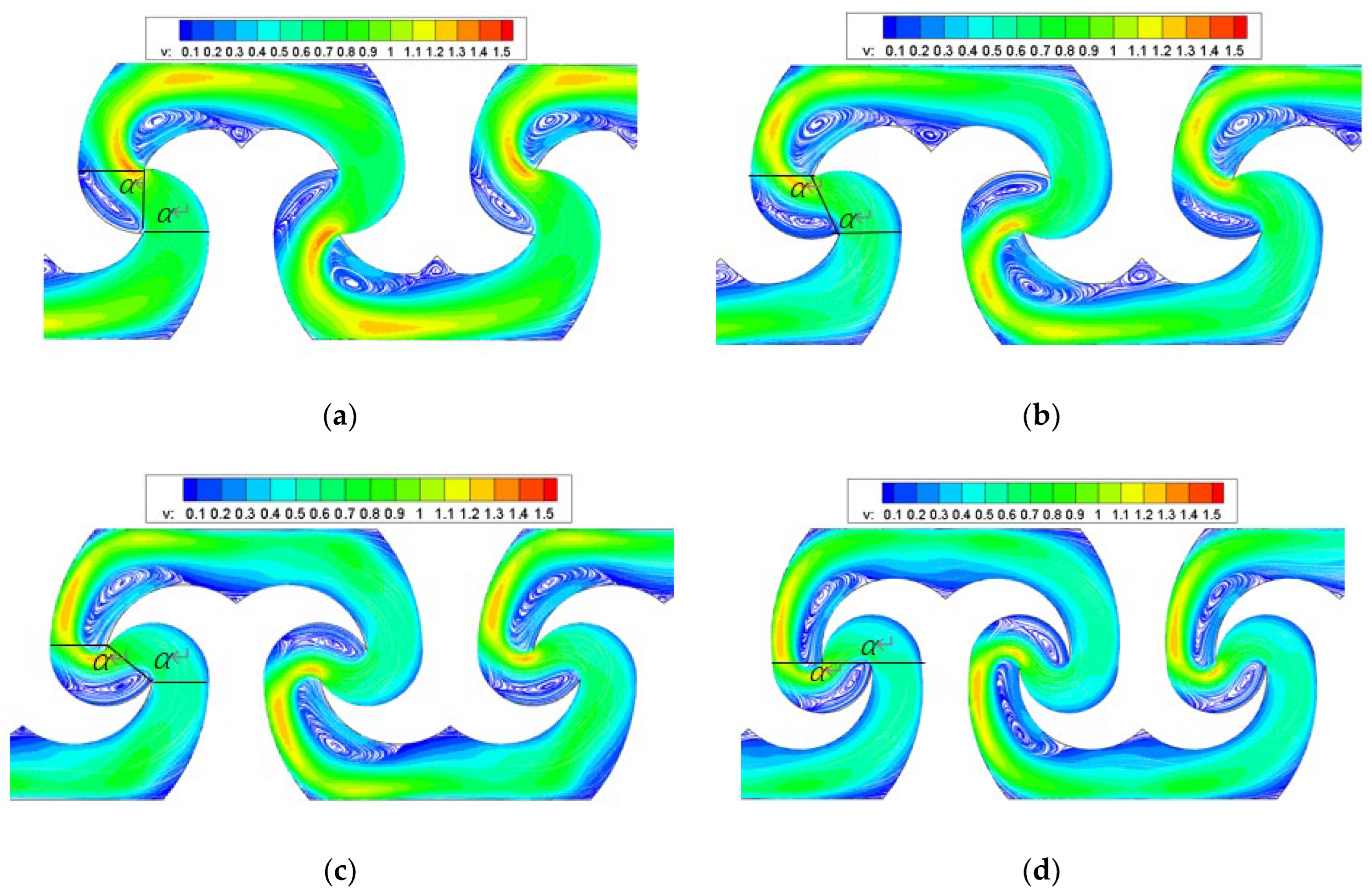
3.2.1. Analysis of the Effect of the Waist-Arc Angle on the Flow Field

The flow field and the energy dissipation mechanism for each crown-to-chord ratio of the Y-shaped emitters were similar, and we used the A1–A4 type emitter as an example for analysis. Flow-field diagrams of the different waist-arc angles at a channel depth plane of 0.5 mm is shown in Figure 7. The figure shows that the channel could be divided into a high-speed mainstream area and a low-speed vortex area, and the latter could increase the degree of turbulence in the channel, intensifying the energy dissipation. The low-speed vortex existed primarily in the waist of the channel and the upper left of the Y-shaped tooth, and the position changed slightly with increases in the waist-arc angle.
When the length of the channel remained unchanged, the number of the emitter channel units, at different waist-arc angles, changed; therefore, the pressure drop ratio before and after the water flow in the channel through the vortex was used to analyze the improvements in the hydraulic performance of the emitter. Figure 8 shows the pressure-distribution cloud maps of the emitters at different waist-arc angles. It was observed from the figure that the pressure in the low-speed vortex area was low, and after the water had flowed through the low-speed vortex area at the waist of the runner and the upper left of the Y-shaped tooth, the pressure dropped sharply, and the pressure energy decreased. The pressure drop ratio in the channel of the emitter, at different waist-arc angles, is shown in Table 5.
As shown in Table 5, for the water flow through the first waist arc of the A1~A4 emitters, the pressure was reduced by 6.89%, 7.84%, 8.69%, and 9.67%, respectively; when flowing through the second waist arc, the pressure decreased by 7.41%, 8.51%, 9.52%, and 10.7%, respectively. It was shown that the pressure-drop ratio before and after the water flow through the low-speed vortex increased with increases in the waist-arc angle, which proved that “when the crown-to-chord ratio was constant, the hydraulic performance of the Y-shaped emitter improved with increases in the waist-arc angle”.

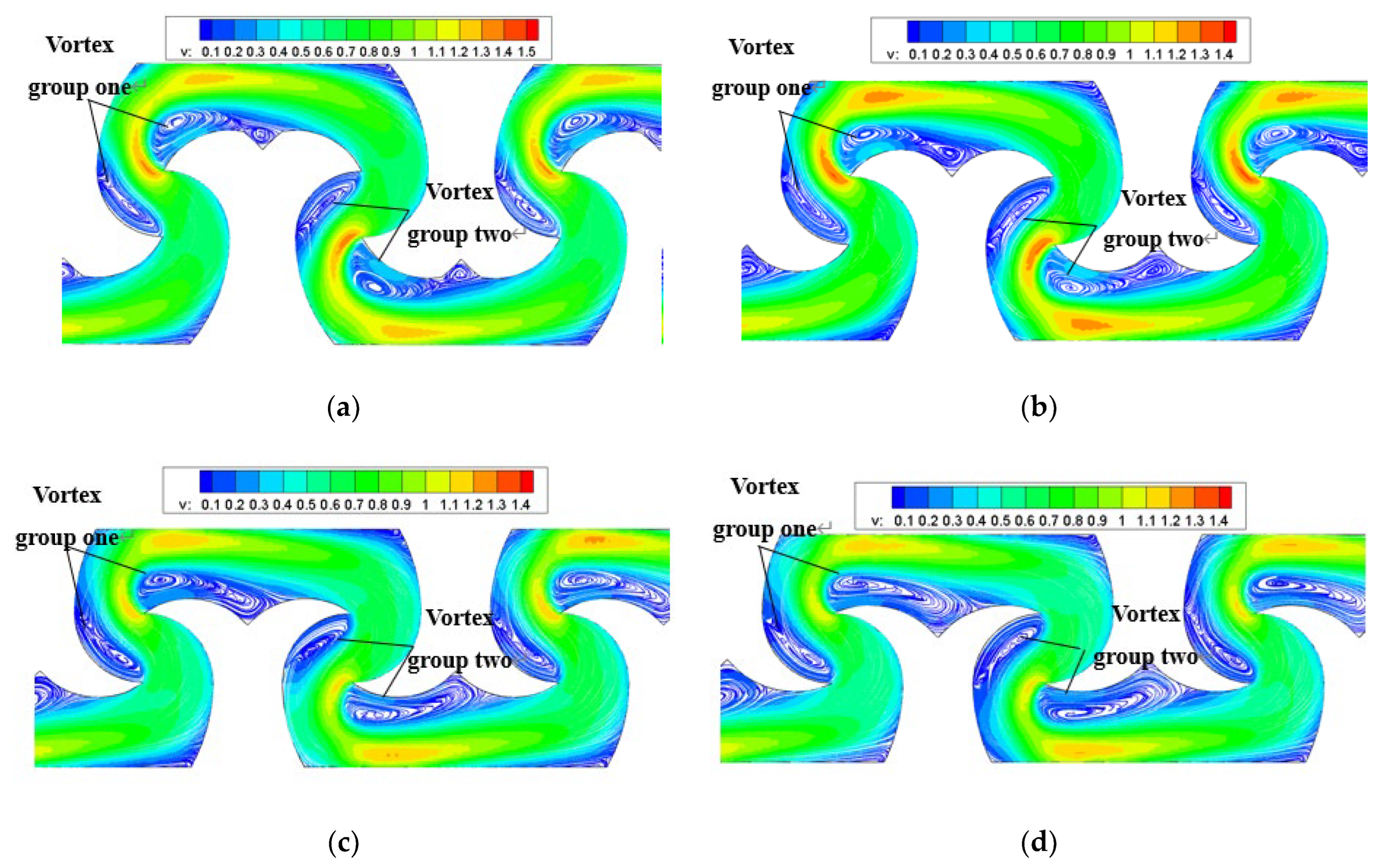
3.2.2. Analysis of the Effect of the Crown-To-Chord Ratio on the Flow Field

The flow field and energy dissipation mechanism at each waist-arc angle of the Y-shaped emitters were similar. We used the A1, B1, C1, and D1 type emitters as an example for analysis. When the waist-arc angle was 90°, the flow field diagram of different crown-to-chord ratios at a channel depth plane of 0.5 mm is shown in Figure 9. The low-speed vortex area existed in the waist of the runner and the upper left of the Y-shaped tooth, and with decreases in the crown-to-chord ratio, the upper left vortex of the Y tooth gradually extended to the middle of the tooth, and the area tended to increase. The total number of units in the channel of the emitter remained constant at different crown-to-chord ratios, and we analyzed the differences in the vortex strength for each channel element of the crown-to-chord ratios.
Vortex strength is the magnitude of the velocity gradient along the direction of the vortex axis when vortex motion is present in a liquid or gas. The greater vortex strength indicated a more obvious energy dissipation of the water flow. The vortex strength was defined as ω × A, where ω is the angular velocity of rotation, A is the cross-sectional area of the vortex, ω = v r ; r is the equivalent radius of the vortex area, and v is the average tangential velocity at the boundary of the vortex region [30]. The total vortex strength in the channel unit of the emitter for each crown-to-chord ratio is shown in Table 6.
As shown in Table 6, the vortex strength of the upper and lower groups of the channel units was almost the same, and as the crown-to-chord ratio decreased, the vortex strength gradually increased, indicated that the emitter hydraulic performance was improving. Therefore, keeping the waist-arc angle unchanged and reducing the crown-to-chord ratio could improve the hydraulic performance of the Y-shaped emitter.

3.3. Optimization of Both Hydraulic and Anti-Clogging Performance

Studies [31] had shown that the anti-clogging performance showed a great correlation with the length and cross-sectional size of the channel; therefore, the most intuitive way to improve the anti-clogging performance of the emitter itself was to shorten the length of the channel and widen the cross-sectional area of the channel.
Though unaffected by the crown-to-chord ratio, the hydraulic performance was best when the waist-arc angle of the Y-shaped emitter was 180°. In order to improve the anti-clogging performance, we attempted to ensure that the channel depth and length remained unchanged, or ensure the channel depth and width remain unchanged, we expanded the channel width or shortened the channel length, to make its pressure-flow curve slope as much as possible the same as the currently-used triangular-channel emitter, in order to achieve the effect of “the two hydraulic performance was similar, but the Y-shaped emitter to improve the performance of anti-clogging “. In order to achieve these purposes, we changed the width or the length of the channel of the Y-shaped emitter to form the A4(1)-A4(5) emitter models, and the parameters of the 5 emitters are shown in Table 7. The pressure-flow curves of each emitter and the triangular-channel (Z-type) emitter are shown in Figure 10. At 10 mH2O inlet pressure, the comparison of the parameters of each emitter and the triangular-channel (Z-type) emitter is shown in Table 8.
As shown in Table 8 and Figure 10, at 10 mH2O inlet pressure, when the Y-shaped emitter waist-arc angle was 180°, if the width of the channel increased by 30% (A4(1) emitter), the design flow was reduced by 13.2% as compared to the triangular-channel (Z-type) emitter, and the slope of the curve was increased by 7.63%. When the width of the channel increased by 20% (A4(3) emitter), the design flow and curve slope of the Y-shaped emitter decreased by 22.3% and 4.53%, respectively, as compared to the triangular-channel (Z-type) emitter. When the channel width of the Y-shaped emitter was increased by 25% (A4(2) emitter), its design flow was reduced by 17.7%, while the curve slope was increased by only 2.09%, as compared to that of the triangular-channel (Z-type) emitter. The two curves of Z and A4(2) in Figure 10a were approximately parallel. This indicated that when the channel width of the Y-shaped emitter, with a waist-arc angle of 180°, increased by nearly 25%, as compared to the commonly-used triangular-channel emitter, the hydraulic performance of the two was similar, and its anti-clogging performance improved due to the increase in the channel width.
When the waist-arc angle of the Y-shaped emitter was 180°, if the channel length was shortened by 31.0% (A4(5) emitter), the design flow and curve slope were reduced by 25.7% and 11.2%, respectively, as compared to the triangular-channel emitter (Z-type). When the channel length of the Y-shaped emitter was shortened by 44.3% (A4(4) emitter), the design flow was reduced by 16.2%, and the curve slope was only reduced by 0.50%, as compared to the triangular-channel (Z-type) emitter. The two curves of Z and A4(4) in Figure 10b were approximately parallel. This indicated that when the channel length of the Y-shaped emitter, with a waist-arc angle of 180°, was shortened by nearly 44.3% as compared to the commonly-used triangular-channel emitter, the hydraulic performance of the two was similar. Due to the shortened length of the channel, the clogging performance improved.
The Y-shaped emitter utilized a continuous large deflection angle of the water flow in the channel, and the generated vortex intensified the energy dissipation, indicating that the hydraulic performance was better than the traditional labyrinth-channel emitter. At the same operating pressure, the Y-shaped emitter provided a more stable and uniform flow, which would be of positive value for improving water-saving capacity in irrigation projects. Therefore, the Y-shaped emitter could be used as a reference for developing and designing high-performance emitters. The Y-shaped emitter is expected to have broad application prospects in water-saving irrigation.

4. Conclusions

Based on a simulation analysis of Y-shaped emitters with various waist-arc angles (α) and crown-to-chord ratios (a:b) at different channel widths and lengths, the following conclusions can be drawn:
  • If the crown-to-chord ratio was kept unchanged, the larger the waist-arc angle was, the greater the pressure drop ratio before and after the water flow through the low-speed vortex area became, and the smaller the design flow of the Y-shaped emitter; this led to improved hydraulic performance.
  • As the crown-to-chord ratio of the Y-shaped emitter decreased, the influence of the waist-arc angle on the design flow and hydraulic performance diminished.
  • If the waist-arc angle remained unchanged, reducing the crown-to-chord ratio could increase the vortex strength inside the channel, thereby reducing the design flow of the emitter and improving the hydraulic performance.
  • As the waist-arc angle of the Y-shaped emitter increased, the influence of the crown-to-chord ratio on the design flow and hydraulic performance diminished; when the Y-shaped emitter waist-arc angle increased to 180°, the crown-to-chord ratio had little to no effect on the design flow or hydraulic performance.
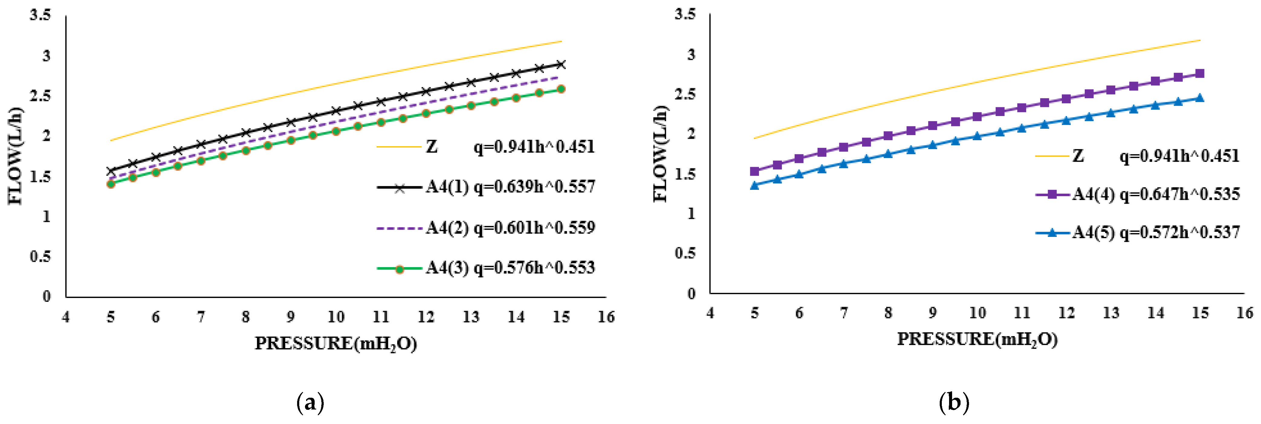
  • When considering both good hydraulic performance and anti-clogging performance, by enlarging the channel width by 25% (A4(2) emitter) or shortening the channel length by 44.3% (A4(4) emitter), the Y-shaped emitter, with a waist-arc angle of 180°, had a similar hydraulic performance to a commonly-used triangular-channel emitter with the same cross-sectional size and channel length.

5. Patents

The content of this research was patented by our team, and the patent information was as follows: Zhiqin, L.; Peisen, D. A Kind of Y-shaped Drip Irrigation Emitter. Chinese patent CN217470914U; Taiyuan, China, 2022.

Author Contributions

C.L. edited the original draft; Z.L. reviewed and edited the draft; P.D. provided software guidance; J.M. obtained the funding; S.L. Investigation. All authors have read and agreed to the published version of the manuscript.

Funding

This work was supported by the National Natural Science Foundation of China (52079085).

Data Availability Statement

The data that support the findings of this study are available from the corresponding author on reasonable request.

Conflicts of Interest

The authors declare no conflict of interest.

References

  1. Geng, S.; Liu, D.; Xia, P. Research on China’s water use efficiency of China based on a comparative analysis. Water. Resour. Devel. Res. 2022, 22, 77–82, (In Chinese with English Abstract). [Google Scholar]
  2. Chen, B.; Chen, F. Discussion on Water-saving Irrigation Technology of Farmland Water Conservancy. J. Agric. Cat. 2023, 13, 176–178, (In Chinese with English Abstract). [Google Scholar]
  3. Shiri, J.; Karimi, B.; Karimi, N.; Kazemi, M.H.; Karimi, S. Simulating wetting front dimensions of drip irrigation systems: Multi criteria assessment of soft computing models—Sciencedirect. J. Hydrol. 2020, 585, 124792. [Google Scholar] [CrossRef]
  4. Lamm, F.R.; Colaizzi, P.D.; Sorensen, R.B.; Bordovsky, J.P.; Dougherty, M.; Balkcom, K.; Zaccaria, D.; Bali, K.M.; Rudnick, D.R.; Peters, R.T. A 2020 Vision of Subsurface Drip Irrigation in the U.S. Trans. ASABE 2021, 64, 1319–1343. [Google Scholar] [CrossRef]
  5. Nogueira, V.H.B.; Diotto, A.V.; Thebaldi, M.S.; Colombo, A.; Silva, Y.F.; de Lima, E.M.; Resende, G.F.L. Variation in the Flow Rate of Drip Emitters in a Subsurface Irrigation System for Different Soil Types. Agric. Water Manag. 2021, 243, 106485. [Google Scholar] [CrossRef]
  6. Zhang, L.; Li, S. Numerical experimental investigation of douche hydraulic performance on drop irrigation of tooth-type labyrinth channel. Water. Resour. Power. 2017, 35, 103–106, (In Chinese with English Abstract). [Google Scholar]
  7. Wei, Q.S.; Shi, Y.S.; Dong, W.C.; Lu, G.; Huang, S.H. Study on hydraulic performance of drip emitters by computational fluid dynamics. Agric. Water. Manag. 2006, 84, 130–136. [Google Scholar] [CrossRef]
  8. Zhou, W.; Zhang, L.; Wu, P.; Cai, Y.; Zhao, X.; Yao, C. Hydraulic performance and parameter optimisation of a microporous ceramic emitter using computational fluid dynamics, artificial neural network and multi-objective genetic algorithm. Biosyst. Eng. 2020, 189, 11–23. [Google Scholar] [CrossRef]
  9. Baghel, Y.; Kumar, J.; Patel, V. CFD Analysis of the Flow Characteristics of In-Line Drip Emitter with Different Labyrinth Channels. J. Inst. Eng. India Ser. A. 2021, 102, 111–119. [Google Scholar] [CrossRef]
  10. Zanca, R.B.; Silva, F.D.; SantAnna, D.O.; Silva, A.T.; Nova, H.F.; Santos, I.F.; Reis, J.A. Modeling and hydraulic performance evaluation of a dripper device coupled to a branched water distribution network. Rev. Ambiente Agua 2019, 14, e2340. [Google Scholar] [CrossRef]
  11. Mattar, M.A.; Alamoud, A.I. Gene expression programming approach for modeling the hydraulic performance of labyrinth-channel emitters. Comput. Electron. Agric. 2017, 142, 450–460. [Google Scholar] [CrossRef]
  12. Saccone, D.; Marchis, M. Optimization of the Design of Labyrinth Emitter for Agriculture Irrigation Using Computational Fluid Dynamic Analysis. AIP Conf. Proc. 2018, 2040, 140013. [Google Scholar]
  13. Zhang, C.; Niu, Y.; Liu, X. Numerical simulation of influence of tooth angle on hyaraulic characteristics of labyrinth emitter. J. Drain. Irrig. 2022, 40, 751–756, (In Chinese with English Abstract). [Google Scholar]
  14. Celik, H.K.; Karayel, D.; Caglayan, N.; Rennie, A.E.; Akinci, I. Rapid prototyping and flow simulation applications in design of agricultural irrigation equipment: Case study for a sample in-line drip emitter: The paper is to study CFD and RP application samples on the design issues associated with agricultural irrigation equipment. Virtual Phys. Prototyp. 2011, 6, 47–56. [Google Scholar]
  15. Du, P.; Li, Z.; Wang, C.; Ma, J. Analysis of the influence of the channel layout and size on the hydraulic performance of emitters. Agric. Water. Manag. 2022, 12, 541. [Google Scholar] [CrossRef]
  16. Patil, S.S.; Nimbalkar, P.T.; Joshi, A. Hydraulic Study, Design & Analysis of Different Geometries of Drip Irrigation Emitter Labyrinth. IJEAT 2013, 2, 455–462. [Google Scholar]
  17. Wang, C.; LI, Z.; Ma, J. Influence of emitter structure on its hydraulic performance based on the vortex. Agric. Water. Manag. 2021, 11, 508. [Google Scholar] [CrossRef]
  18. Feng, J.; Li, Y.; Wang, W.; Xue, S. Effect of optimization forms of flow path on emitter hydraulic and anti-clogging performance in drip irrigation system. Irrig. Sci. 2018, 36, 37–47. [Google Scholar] [CrossRef]
  19. Wu, F.; Dong, X.; Wu, Y.; Ma, D.; Feng, X. Hydraulic properties of the flow in a gradual shrinking and sudden enlarging channel. J. N. China Univ. Water Res. Electric Power. 2017, 38, 7, (In Chinese with English Abstract). [Google Scholar]
  20. Guo, L.; Bai, D.; Wang, X.; He, J.; Zhou, W.; Cheng, P. Numerical simulation and verification of hydraulic performance and energy dissipation mechanism of two-ways mixed flow emitter. Trans. CSAE 2017, 33, 100–107, (In Chinese with English Abstract). [Google Scholar]
  21. Xing, S.; Wang, Z.; Zhang, J.; Liu, N.; Zhou, B. Simulation and verification of hydraulic performance and energy dissipation mechanism of perforated drip irrigation emitters. Water 2021, 13, 171. [Google Scholar] [CrossRef]
  22. Zhu, Y.; Cao, W.; Liu, J. Study on structural design and hydraulic characteristic of a new type segmented rod emitter. Water. Sav. Irrig. 2020, 49, 5, (In Chinese with English Abstract). [Google Scholar]
  23. Li, Y.; Feng, X.; Liu, Y.; Han, X.; Liu, H.; Sun, Y.; Li, H.; Xie, Y. Research on hydraulic properties and energy dissipation mechanism of the novel water-retaining labyrinth channel emitters. Agronomy 2022, 12, 1708. [Google Scholar] [CrossRef]
  24. Wang, C.; Li, Z.; Xu, T.; Kang, M.; Song, X. Computational Experiments on Frictional Head Loss in Labyrinth Channel. J. Tai’ Yuan Univ. Technol. 2019, 50, 125–129. [Google Scholar]
  25. Camp, C.R. Subsurface drip irrigation: A review. Trans. ASAE 1998, 41, 1353–1367. [Google Scholar] [CrossRef]
  26. Kang, M. Influence of Double Internal Tooth Parameters on Hydraulic Performance of Labyrinth Irrigation Device. Master’s Thesis, Taiyuan University of Technology, Taiyuan, China, 2018. [Google Scholar]
  27. Zhai, Y.; Wu, W.; Wang, Z.; Hu, Y.; Xu, H. Analysis of the effect of pressure on hydraulic and anti-clogging performance of the channel unit of the irrigator based on ansys fluent software. Water Sav. Irrig. 2022, 59, 47–53, (In Chinese with English Abstract). [Google Scholar]
  28. Xu, T.; Zhang, L. Influence and analysis of structure design and optimization on the performance of a pit drip irrigation emitter*. Irrig. Drain. 2020, 69, 633–645. [Google Scholar] [CrossRef]
  29. Moriasi, D.N.; Arnold, J.G.; Arnold, J.G.; Bingner, R.L.; Bingner, R.L.; Veith, T.L. Model Evaluation Guidelines for Systematic Quantification of Accuracy In Watershed Simulations. Trans. ASABE. 2007, 50, 885–900. [Google Scholar] [CrossRef]
  30. Zhichang, Z. Hydraulics; China Water & Power Press: Beijing, China, 2016; Volume 7, pp. 272–277. [Google Scholar]
  31. Wen, S.; Niu, W.; Wu, M.; Zhang, W.; Li, X.; Yang, X. Dynamic Characteristics of Different Emitters Clogging in Drip Irrigation with Muddy Water. Trans. CSAM 2020, 51, 287–294, (In Chinese with English Abstract). [Google Scholar]
Figure 1. Schematic diagram of the side-type drip irrigation belt arrangement.
Agriculture 13 01160 g001
Figure 2. Schematic diagram of Y-shaped emitter channel.
Agriculture 13 01160 g002
Figure 3. Physical model of Y-shaped emitter.
Agriculture 13 01160 g003
Figure 4. Test system. Note: 1, water supply system; 2, test bench; 3, supply water pipeline; 4, pressure-regulating valve; 5, return water pipeline; 6, precision pressure gauge; 7, test model; 8, measuring cylinder.
Agriculture 13 01160 g004
Figure 5. (a) Pressure-flow curves of A-type and Z-type emitters. (b) Pressure-flow curves of B-type emitter. (c) Pressure-flow curves of C-type emitter. (d) Pressure-flow curves of D-type emitter.
Agriculture 13 01160 g005aAgriculture 13 01160 g005b
Figure 6. (a) Pressure-flow curves of A1, B1, C1, and D1 emitters. (b) Pressure-flow curves of A2, B2, C2, and D2 emitters. (c) Pressure-flow curves of A3, B3, C3, and D3 emitters. (d) Pressure-flow curves of A4, B4, C4, and D4 emitters.
Agriculture 13 01160 g006
Figure 7. (a) Flow-field diagram of A1 emitter. (b) Flow-field diagram of A2 emitter. (c) Flow-field diagram of A3 emitter. (d) Flow-field diagram of A4 emitter.
Agriculture 13 01160 g007
Figure 8. (a) Pressure distribution cloud map of A1 emitter. (b) Pressure distribution cloud map of A2 emitter. (c) Pressure distribution cloud map of A3 emitter. (d) Pressure distribution cloud map of A4 emitter.
Agriculture 13 01160 g008
Figure 9. (a) Flow-field diagram of A1 emitter. (b) Flow field-diagram of B1 emitter. (c) Flow-field diagram of C1 emitter. (d) Flow-field diagram of D1 emitter.
Agriculture 13 01160 g009
Figure 10. (a) Pressure-flow curve of emitter with different channel widths. (b) Pressure-flow curve of emitter with different channel lengths.
Agriculture 13 01160 g010
Table 1. Parameters of the Y-shaped emitter.
NumberCrown Height
(a) (mm)
Chord Length
(b) (mm)
Crown-To-Chord
Ratio (a:b)
Waist-Arc
Angle (α)
Number
of Units
Channel Length (mm)Concave-Angle Width (e) (mm)Concave-Angle Depth (n) (mm)
A10.63.06:3090°50299.00.50.3
A2120°43300.30.80.4
A3150°39300.71.40.3
A4180°38303.11.80.4
B10.43.04:3090°50299.01.20.3
B2120°43300.31.30.4
B3150°39300.71.50.4
B4180°38303.11.60.4
C10.23.02:3090°50299.01.40.3
C2120°43300.31.60.4
C3150°39300.71.80.5
C4180°38303.12.20.5
D10.13.01:3090°50299.01.40.4
D2120°43300.32.00.3
D3150°39300.72.20.3
D4180°38303.12.00.5
Table 2. Numerical simulation and model test results and errors.
MethodPressure h (mH2O)
4.986.207.639.0610.4911.9113.3414.77
Numerical simulation(L/h)3.784.304.845.355.776.196.596.93
Model test (L/h)3.804.324.865.375.856.286.717.11
Relative error (%)0.530.460.410.371.371.431.792.53
Note: Relative error = (Model test—Numerical simulation)/Model test × 100%.
Table 3. Variations of design flow and slope of the curve for emitters with 4 waist-arc angles at each crown-to-chord ratio (Includes comparison of A1 emitter and Z emitter).
NumberCrown-To-Chord RatioWaist-Arc
Angle
Design Flow q (L/h)Slope of the Curve kDesign Flow Variation (%)Slope of Curve Variation (%)Formula
of Parameters Variation
Z————2.650.1192——————
A16:3090°2.170.1202−18.1+0.84(WA1-WZ)/WZ
A2120°1.820.0994−16.1−17.3(WA2-WA1)/WA1
A3150°1.720.0921−20.7−23.4(WA3-WA1)/WA1
A4180°1.590.0864−26.7−28.1(WA4-WA1)/WA1
B14:3090°2.010.1058——————
B2120°1.740.0968−13.4−8.50(WB2-WB1)/WB1
B3150°1.700.0919−15.4−13.1(WB3-WB1)/WB1
B4180°1.590.0883−20.9−16.5(WB4-WB1)/WB1
C12:3090°1.770.1031——————
C2120°1.670.0930−5.65−9.80(WC2-WC1)/WC1
C3150°1.660.0904−6.21−12.3(WC3-WC1)/WC1
C4180°1.590.0879−10.2−14.7(WC4-WC1)/WC1
D11:3090°1.660.0956——————
D2120°1.630.0873−1.81−8.68(WD2-WD1)/WD1
D3150°1.590.0871−4.22−8.89(WD3-WD1)/WD1
D4180°1.560.0862−6.02−9.83(WD4-WD1)/WD1
Note: +, increase; −, decrease, which is consistent for all following tables. W in the eighth column represents q and k in the fourth and fifth columns, which is consistent for all following tables.
Table 4. Variations of design flow and slope of the curve for emitter with 4 crown-to-chord ratios at each waist-arc angle.
NumberWaist-Arc
Angle
Crown-To-Chord RatioDesign Flow q (L/h)Slope of the Curve kDesign Flow Variation (%)Slope of Curve Variation (%)Formula
of Parameters Variation
A190°6:302.170.1202——————
B14:302.010.1058−7.37−12.0(WB1-WA1)/WA1
C12:301.770.1030−18.4−14.3(WC1-WA1)/WA1
D11:301.660.0956−23.5−20.5(WD1-WA1)/WA1
A2120°6:301.820.0994——————
B24:301.740.0968−4.40−2.62(WB2-WA2)/WA2
C22:301.670.0930−8.24−6.43(WC2-WA2)/WA2
D21:301.630.0873−10.4−12.2(WD2-WA2)/WA2
A3150°6:301.720.0921——————
B34:301.700.0919−1.16−0.22(WB3-WA3)/WA3
C32:301.660.0904−3.49−1.84(WC3-WA3)/WA3
D31:301.590.0871−7.56−5.43(WD3-WA3)/WA3
A4180°6:301.590.0864——————
B44:301.590.08830+2.20(WB4-WA4)/WA4
C42:301.590.08790+1.73(WC4-WA4)/WA4
D41:301.560.0862−1.89−0.23(WD4-WA4)/WA4
Table 5. Pressure drop ratio in the channel of the emitter at different waist-arc angles.
NumberCrown-To-Chord RatioWaist-Arc AngleWaist Arc OneWaist Arc Two
Pre-Vortex Pressure (Pa)Post-Vortex Pressure (Pa)Pressure Drop Ratio (%)Pre-Vortex Pressure (Pa)Post-Vortex Pressure (Pa)Pressure Drop Ratio (%)
A16:3090°870081006.89810075007.41
A2120°10,20094007.84940086008.51
A3150°11,50010,5008.6910,50095009.52
A4180°12,40011,2009.6711,20010,00010.7
Note: pressure drop ratio = p r e p o s t p r e × 100%.
Table 6. Vortex strength (in a channel unit).
NumberCrown-To-Chord RatioVortex GroupTotal Area of Vortex (mm2)Total Vortex
Strength
A16:30One1.24430.436
Two1.13870.421
B14:30One1.40850.511
Two1.43760.519
C12:30One1.60310.632
Two1.52680.611
D11:30One1.69550.714
Two1.67670.698
Table 7. Parameters of A4 emitter with different channel widths and lengths.
NumberWaist-Arc
Angle
Channel Depth (mm)Concave-Angle Width (mm)Concave-Angle Depth (mm)Channel Width (mm)Number
of Units
Channel Length (mm)
A4(1)180°1.01.80.41.3031 302.9
A4(2)180°1.01.80.41.2532 303.1
A43)180°1.01.80.41.2033 302.7
A4(4)180°1.01.80.41.0021 167.1
A4(5)180°1.01.80.41.0026 207.1
Note: A4(1)–A4(3) emitter only to expand the width of the channel; A4(4) and A4(5) emitter only to shorten the length of the channel.
Table 8. Variation of each parameter for emitter with different channel widths and lengths.
NumberChannel Width (mm)Channel Length (mm)Design Flow (L/h)Slope of the CurveDesign Flow Variation (%)Slope of Curve Variation (%)Channel Width Variation (%)Channel Length Variation (%)
Z1.00300.22.650.1192————————
A4(1)1.30302.92.300.1283−13.2+7.63+30.0−0.89
A4(2)1.25303.12.180.1217−17.7+2.09+25.0−0.96
A4(3)1.20302.72.060.1138−22.3−4.53+20.0−0.83
A4(4)1.00167.12.220.1186−16.2−0.500−44.3
A4(5)1.00207.11.970.1058−25.7−11.20−31.0
Note: Variation of parameter = A 4 z z .
Disclaimer/Publisher’s Note: The statements, opinions and data contained in all publications are solely those of the individual author(s) and contributor(s) and not of MDPI and/or the editor(s). MDPI and/or the editor(s) disclaim responsibility for any injury to people or property resulting from any ideas, methods, instructions or products referred to in the content.

