Article

A Vibration Reduction Control Method for Tractor Rear Hydraulic Hitch Based on Pressure Feedback

1
College of Mechanical Engineering, Jiangsu Ocean University, No. 59 Cangwu Road, Haizhou District, Lianyungang 222005, China
2
School of Mechatronic Engineering, China University of Mining and Technology, No. 1 Daxue Road, Xuzhou 221116, China
3
Beijing Key Laboratory of Optimized Design for Modern Agricultural Equipment, College of Engineering, China Agricultural University, No. 17 Tsinghua East Road, Haidian District, Beijing 100091, China
*
Author to whom correspondence should be addressed.
Agriculture 2023, 13(8), 1546; https://doi.org/10.3390/agriculture13081546
Submission received: 25 June 2023 / Revised: 19 July 2023 / Accepted: 31 July 2023 / Published: 2 August 2023
(This article belongs to the Section Agricultural Technology)

Abstract

:
Tractors transporting heavy hitches tend to tilt severely, resulting in significant dynamic loads on the front axle and affecting handling stability. Tractors and rear hitches can be considered vibration systems with two coupled masses. Thus, active damping control strategies between tractors and rear hitches are proposed in this study. The complexity and versatility of tractor hydraulic hitching during tractor transit transport are considered. A method of improving the tractor hydraulic hitch damping ratio with pressure feedback is proposed. The dynamic characteristics of the pressure feedback hydraulic hitch system are analyzed. A dynamic model of the tractor transfer transport unit is established, and a numerical simulation is carried out to verify the effectiveness of the proposed hydraulic hitch vibration reduction control strategy based on pressure feedback. A real test platform for tractor vibration reduction control is built. The test results show that the pressure feedback vibration reduction control method proposed in this paper affects tractor pitching motion suppression. In addition, the proposed control strategy does not require a force pin sensor. Tractor hydraulic hitch damping control costs are reduced. The vibration reduction control strategy proposed in this study has high reliability and can be used as a reference for non-road-vehicle vibration reduction control.

1. Introduction

The electro-hydraulic hitching device plays a crucial role in agricultural tractor transit transportation. Agricultural tractors have a growing number of functions. In addition to fieldwork tasks, most tractors have transport functions. Locking is usually used in the process of tractor transportation. Agricultural tractors transport heavy-duty hitching equipment. The tractor has a large pitching motion, which results in a large dynamic load on the front axle and affects the driver’s operating comfort and safety [1]. Damping control of electro-hydraulic hitch devices can greatly improve the smoothness of tractor transit transportation and has high research value. The research on the tractor hydraulic hitch mainly focuses on the operating conditions of tractor plowing. The main control methods include position control to maintain a relative position between the implement and the tractor [2], draft control to stabilize the tractor’s traction [3], draft position control that combines the advantages of position control and draft control [4], and pressure control to increase the vertical load on the rear wheels [5].
The research on electro-hydraulic hitch systems has a long history. Yin et al. [6,7] reduced the pressure fluctuation of the hydraulic cylinder after adding an accumulator device to the tractor’s hydraulic hitch system, thus restraining the pitching movement of the tractor. Rexroth [8] developed a tractor rear hitch damper control system, significantly reducing pressure fluctuations in the hydraulic hitch system. The influencing factors of tractor vibration were analyzed. The relationship between tractor vibration factors and vertical force variations of lower articulation points was analyzed in Cheng et al. [9], and the control method of tractor vibration reduction was studied [10]. The dynamic pressure feedback method was applied to improve the dynamic damping of the electro-hydraulic hitch system in the document [11]. Enlai et al. [12] carried out research on vibration reduction control of the agricultural tractor front axle.
The tractor hydraulic hitch system has very low damping, leading to system instability under tractor hitch lifting and road excitation, a poor stability margin, significant pressure fluctuations, and other phenomena. Active damping of hydraulic systems based on pressure feedback has been around for decades [13]. It is also used in mobile machine structures, large-inertia load device movement, hydraulic servo controller design, hydro-dynamic control, and energy-saving active dampers [14,15,16,17,18]. The method of designing outlet throttle holes considering system dampness is also involved [19,20]. Meanwhile, Axin et al. proposed an active damping design method for an inlet orifice [21] based on the pressure feedback principle. Rahmfeld and Ivantysynova provided a good overview of the methods used in non-road vehicles and mechanical vibration. The active damping methods mentioned in the document [22] are more complex and less universal for off-highway machinery. In contrast, pressure feedback is an active damping control method for hydraulic systems, which is very effective and powerful but is often overlooked in improving hydraulic system damping. Analysis using different types of filters under pressure feedback is given in the document [23]. However, there is limited research on tractor vibration reduction control based on pressure feedback, and the pressure feedback method is applied to the tractor electro-hydraulic hitch system. The proposed control strategy does not require a force pin sensor. The cost of damping control for the tractor hydraulic hitch has been reduced.
A control strategy for tractor rear-hitch vibration reduction based on pressure feedback is proposed in this paper. Considering the non-linear disturbance in the system, a comprehensive mathematical model covering multiple factors is established. The effectiveness of the proposed control strategy is verified by numerical simulation. The control strategy is tested on the tractor test platform.
This paper is organized as follows. The “Nonlinear mathematical model of hydraulic hitch system” section describes the establishment process of the kinematic and dynamic model of the hitch mechanism. In the “Design of pressure feedback correction link” section, the pressure feedback coefficient calculation method is provided, and the analysis results of dynamic characteristics of the closed-loop system are given. The “Experimental verification” section introduces the experimental design, experimental results, and corresponding analysis. The conclusion section provides the conclusion of the article.

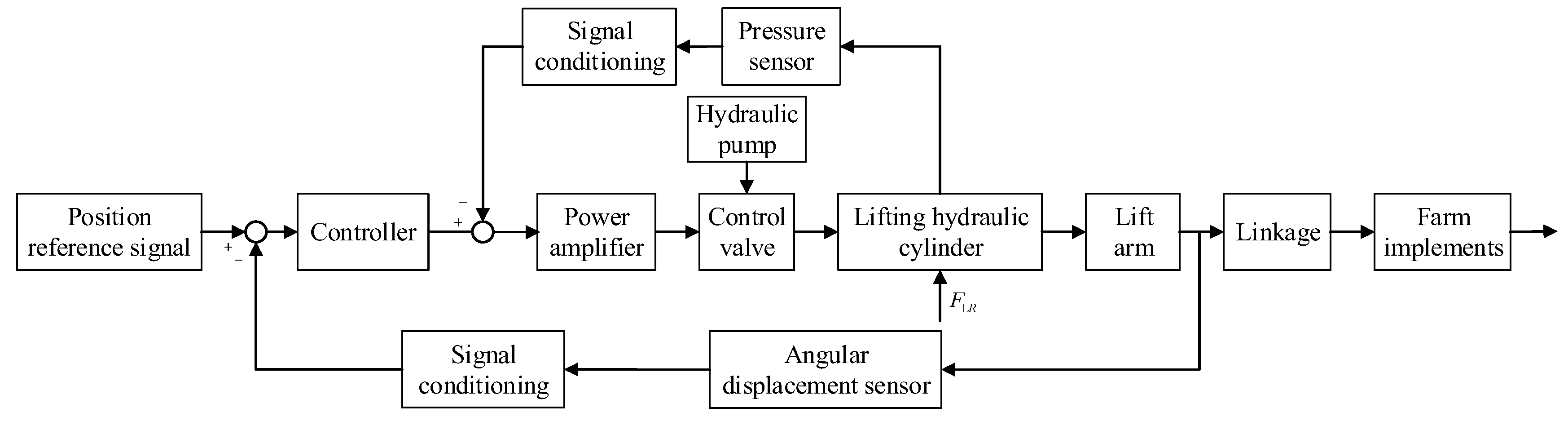
2. Mathematical Model of the Hydraulic Hitch System

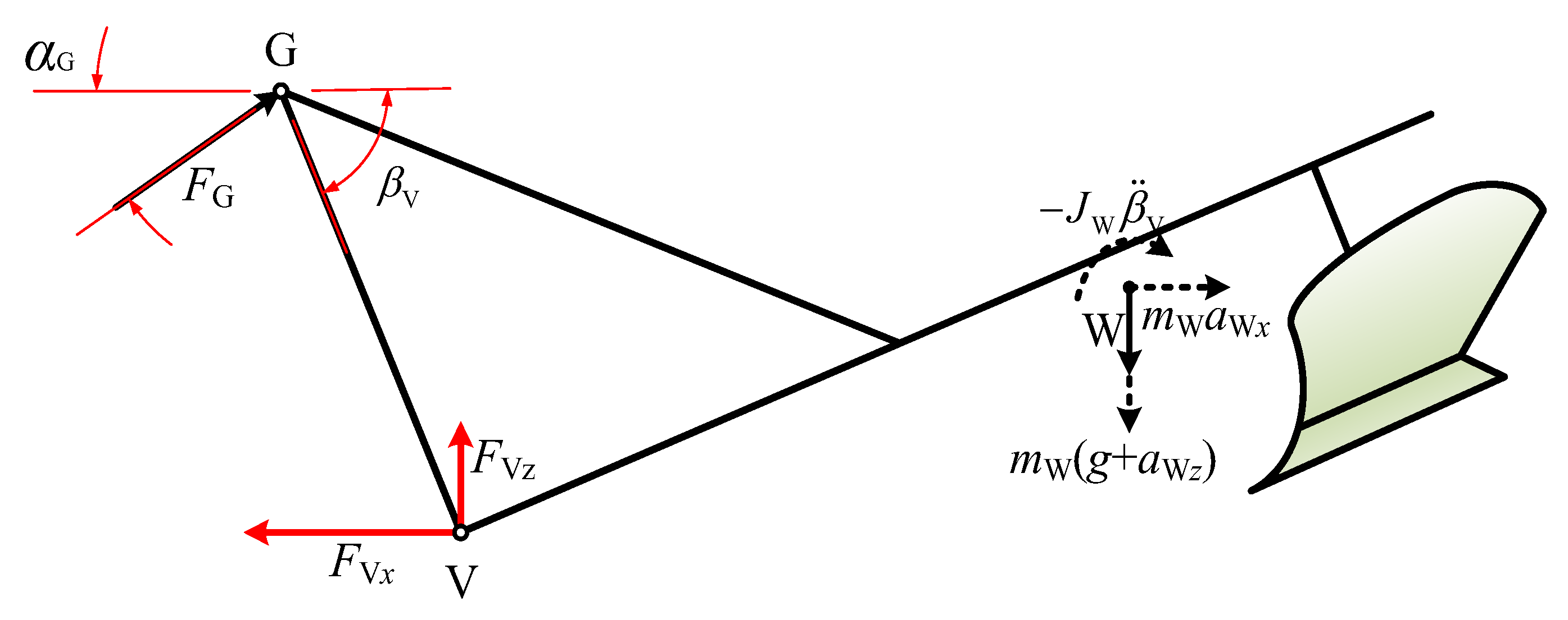
2.1. Kinematic Analysis of Linkage

The tractor hydraulic hitch structure is shown in Figure 1. It mainly includes triangular ANC composed of lifting arm ND and hydraulic cylinder AC; quadrangular NDEB composed of pulling rod BV, lifting rod DE, and lifting arm ND; and another quadrangular mechanism MGVB composed of pulling rod MG, pulling rod BV, and tools. The horizon is set to the horizontal axis x, and the tractor’s forward direction is positive. The vertical line of the rear wheel axis O2 passing through the tractor is the z-axis, and the upward movement is positive. The intersection point of the two axes is the o point, and a fixed-plane reference Cartesian coordinate system xoz is established.
In the triangle ANC, there is the following equation:
{ x N l NC cos α C = x A ( l AC 0 + x L ) cos α AC z N + l NC sin α C = z A + ( l AC 0 + x L ) sin α AC
where lAC0 is the shortest length of the lifting hydraulic cylinder (m); lNC is the length of the NC section of the lifting arm (m); xL is the displacement of the piston (m); αAC is the angle between the axis of the lifting hydraulic cylinder and the horizontal direction (rad); xA and zA are the coordinates of the hydraulic cylinder support point A; and xN and zN are the coordinates of the lifting arm hinge point N.
Then, the included angle in the horizontal direction of the lift arm NC is
α C = arcsin ( z A + ( l AC 0 + x L ) sin α AC z N l NC )
The following geometric relations can be obtained from Figure 1:
{ β AN = arctan ( x N x A z N z A ) α AC = α AN arccos ( l AN 2 + ( l AC 0 + x L ) 2 l NC 2 2 l AN ( l AC 0 + x L ) ) l AN = ( z N z A ) 2 + ( x N x A ) 2 α D = α C + arccos ( l NC 2 + l ND 2 l CD 2 2 l NC l ND )
where lAN is the distance between the hydraulic cylinder support point A and the lifting arm hinge point N (m); lND is the length of the ND section of the lifting arm (m); αAN is the angle between the line connecting the hydraulic cylinder support point A and the lifting arm hinge point N, and the horizontal direction (rad); βAN is the angle between the line connecting the hydraulic cylinder support point A and the lifting arm hinge point N, and the vertical direction (rad); and αD is the angle between the lifting arm and the horizontal direction (rad).
The coordinate of lift arm pin D relative to the coordinate origin is
{ x D = x N l ND cos α D z D = z N + l ND sin α D
Generally, the height from the ground of the tractor hitch is obtained indirectly by measuring the angle of the lift arm. The calculation formula for the rotation angle of the lifting arm is
α ANC = arccos ( l AN 2 + l NC 2 ( l AC 0 + x L ) 2 2 l AN l NC )
The first derivative of Formula (1) with respect to time is calculated as
{ x ˙ N + l NC α ˙ C sin α C = x ˙ A x ˙ L cos α AC + ( l AC 0 + x L ) α ˙ AC sin α AC z ˙ N + l NC α ˙ C cos α C = z ˙ A + x ˙ L sin α AC + ( l AC 0 + x L ) α ˙ AC cos α AC
In the four-link NDEB, the following equation exists:
{ x N l NC cos α D l DE cos β E = x B l BE cos α E z N + l NC sin α D l DE sin β E = z B + l BE sin α E
where lDE is the length of the lifting rod (m); lBE is the length of the front section of the lower link rod; αE is the angle between the lower link and the horizontal direction (m); and xB and zB are the coordinates of the lower hinge point B.
Thus, the included angle between the bottom link BE and the horizontal direction is
α E = arcsin ( z D z B l DE sin β E l BE )
According to Figure 1, the following geometric relations can be obtained:
{ β E = π α NDE α D β BN = arctan ( x N x B z N z B ) l BD = l BN 2 + l DN 2 + 2 l BN l DN sin ( α D β BN ) α NDE = arccos ( l DN 2 + l BD 2 l BN 2 2 l DN l BD ) + arccos ( l BD 2 + l DE 2 l BE 2 2 l BD l DE )
where lBD is the distance between the lower hinge point B and the lifting arm point D (m); lBN is the distance between the lower hinge point B and the lifting arm hinge point N (m); αNDE is the angle between the lifting arm ND and the lifting rod DE (rad); βE is the angle between the lifting rod passing through point D and the horizontal direction (rad); and βBN is the angle between the line connecting the lower hinge point B and the lifting arm hinge point N, and the vertical direction (rad).
The coordinate of the pull-down rod pin axis E relative to the coordinate origin is
{ x E = x B l BE cos α E z E = z B + l BE sin α E
The first derivative of Formula (7) with respect to time is calculated as
{ x ˙ N + l ND α ˙ C sin α D + l DE β ˙ E sin β E = x ˙ B + l BE α ˙ E sin α E z ˙ N + l ND α ˙ C cos α D l DE β ˙ E cos β E = z ˙ B + l BE α ˙ E cos α E
It can be seen from Figure 1 that in quadrilateral MGVB, the following equation applies:
{ x B l BV cos α E = x M l GM cos α G l GV cos β V z B + l BV sin α E = z M + l GM sin α G l GV sin β V
where lBV is the length of the lower link, lGM is the length of the top link (m); lGV is the height of the implement column; αG is the angle between the top link and the horizontal direction (m); βV is the angle between the tool column GV passing through the G point and the horizontal direction (rad); and xM and zM are the coordinates of the hinge point M of the upper link.
Thus, the included angle between the top link MG and the horizontal direction is
α G = arcsin ( z B z M + l BV sin α E + l GV sin β V l GM )
The following geometric relations can be obtained from Figure 1:
{ β V = α BVG α E β BM = arctan ( x B x M z M z B ) l MV = l BM 2 + l BV 2 2 l BM l BV sin ( α E + β BM ) α BVG = arccos ( l MV 2 + l BV 2 l BM 2 2 l MV l BV ) + arccos ( l MV 2 + l GV 2 l GM 2 2 l MV l GV )
where lBM is the distance between the hinge point B of the lower link and the hinge point M of the upper link(m); and lMV is the distance between the hinge point M and V of the upper link (m).
The length of the upper link is adjustable. When the lower link is in the horizontal position, the upright post of the farm tool should be vertical to the ground. From this, it can be determined that the working length lMG of the upper link is
l MG = ( l BV ( x B x M ) ) 2 + ( l GV ( z M z B ) ) 2
The coordinate of the V point on the pull-down bar relative to the coordinate origin is
{ x V = x B l BV cos α E z V = z B + l BV sin α E
The coordinate of point G on the top link is
{ x G = x M l GM cos α G z G = z M + l GM sin α G
The first derivative of Formula (12) with respect to time is calculated as
{ x ˙ B + l BV α ˙ E sin α E = x ˙ M + l GM α ˙ G sin α G + l GV β ˙ V sin β V z ˙ B + l BV α ˙ E cos α E = z ˙ M + l GM α ˙ G cos α G l GV β ˙ V cos β V
The relationship between the middle plow tip P and the centroid W of the farm implement is as follows.
{ x W = x M l GM cos α G l GW cos ( β V β W ) z W = z M + l GM sin α G l GW sin ( β V β W )
where βW is the angle between the point G of the implement column and the horizontal direction where the centroid W of the implement passes through the point G (rad).
The first derivative of Formula (19) with respect to time is calculated as
{ x ˙ W = x ˙ B + l BV α ˙ E sin α E l GV β ˙ V sin β V + l GW β ˙ V sin ( β V β W ) z ˙ W = z ˙ B + l BV α ˙ E cos α E + l GV β ˙ V cos β V l GW β ˙ V cos ( β V β W )
To make an overall analysis of the relationship between the tractor and the movement of the machine, the mathematical relationships can be found in combination with Formulas (6), (11), (18) and (20):
{ x ˙ B x ˙ M = l GM α ˙ G sin α G + l GV β ˙ V sin β V l BV α ˙ E sin α E z ˙ B z ˙ M = l GM α ˙ G cos α G l GV β ˙ V cos β V l BV α ˙ E cos α E z ˙ W z ˙ M = l GM α ˙ G cos α G l GW β ˙ V cos ( β V β W ) z ˙ N z ˙ B = l BE α ˙ E cos α E l ND α ˙ C cos α D + l DE β ˙ E cos β E x ˙ N x ˙ B = l BE α ˙ E sin α E l ND α ˙ C sin α D l DE β ˙ E sin β E
The angular velocity restraint relation of each bar mechanism can be obtained. For the convenience of the whole unit, the simulation model is established, and the state equation of the system is rewritten in the following general form.
X = A n α
where
X = [ x ˙ B x ˙ M z ˙ B z ˙ M z ˙ N z ˙ B x ˙ N x ˙ B z ˙ W z ˙ M ] T ,   α = [ α ˙ G β ˙ V α ˙ E β ˙ E α ˙ C ] T ,   and A n = [ l GM sin α G l GV sin β V l BV sin α E 0 0 l GM cos α G l GV cos β V l BV cos α E 0 0 0 0 l BE cos α E l DE cos β E l ND cos α D 0 0 l BE sin α E l DE sin β E l ND sin α D l GM cos α G l GW cos ( β V β W ) 0 0 0 ]

2.2. Dynamic Analysis of the Hitch System

The force analysis of the tractor hydraulic hitch mainly includes the force analysis of farm implements (Figure 2), the force analysis of the pull-down rod (Figure 3), and the force analysis of the lift arm (Figure 4).
To simplify the analysis, the mass of each link is ignored, so the top link and lifting rod can be regarded as two force rods. Take farm tools as the research object, as shown in Figure 2. The forces on farm tools include the gravity mwg of farm tools (mathematical model reference), the force FG at the upper hitch point, and the troops FVx and FVz projected by the lower hitch point V in the horizontal and vertical directions.
According to the plane d’Alembert principle of rigid bodies, it can be obtained that
{ F G cos α G F V x + m W a W x = 0 F G sin α G + F Vz m W a Wz m W g = 0 F G l GV sin ( β V + α G ) m W ( x V x W ) a Wz + J W β ¨ V + m W a W x ( z V z W ) m W g ( x V x W ) = 0
Take the tie rod BE as the research object. The forces on the pull-down rod BE include the horizontal and vertical parties FVx and FVz at the lower hitch point V, respectively; the forces FVx and FVz along the connecting line direction of the front; and the force FE at the hinge point E of the lifting rod.
Taking the lift arm as the research object, the force on the lift arm includes the lift rod tension FE and the hydraulic cylinder thrust FC, and the torque of the lift arm axis N is obtained as follows:
F C = l ND sin ( α NDE ) l NC sin ( α AC α C ) F E

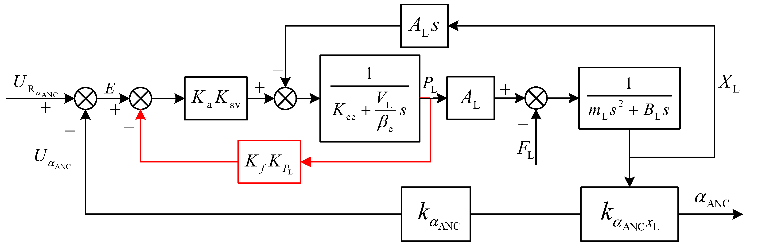
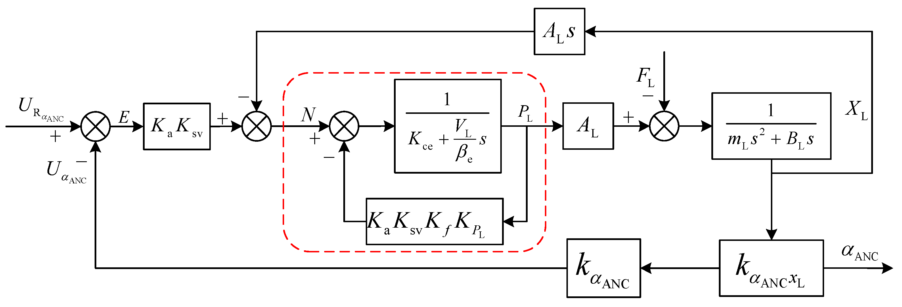
3. Design of Pressure Feedback Correction Link

When a tractor transports a farm implement, it uses a lift arm angle sensor to measure the position of the farm executed relative to the tractor. The relative position of the farm implements to the tractor is kept constant by adjustment. The relative position remains unchanged to ensure the passability and safety of transport of agricultural implements. By comparing the feedback signal of the lift arm angle sensor with the set signal, the system deviation is used as input to the controller. The proportional valve is controlled by a proportional amplifier to achieve position control of the tractor’s electro-hydraulic hitch system. In this study, pressure feedback correction is carried out based on an electro-hydraulic hitch position control system to improve system damping and achieve a vibration reduction effect. The control scheme of the vibration damper system is shown in Figure 5.

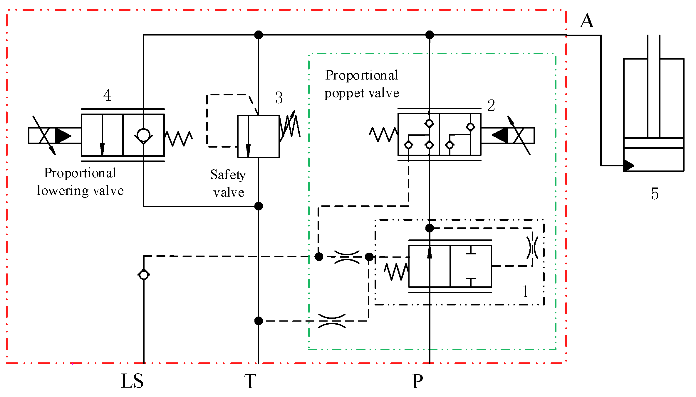
3.1. Nonlinear Mathematical Model of Hydraulic System

The principle of the electro-hydraulic hitch hydraulic valve is shown in Figure 6, composed of the proportional lifting valve, proportional lowering valve, safety valve, and single-acting cylinder. LS is the feedback port, T is the return port, A is the working port, and P is the inlet port. In order to ensure excellent speed regulation characteristics of the proportional valve, a pressure compensation valve is added. The return oil relies on the gravity of the implement.
In the process of establishing the mathematical model of the hydraulic system, assuming that there is no elastic load in the system, ignoring the viscous damping coefficient on the piston, and ignoring the influence of oil density and compressibility, the return oil pressure is 0.
(1) Pressure flow characteristic equation of electro-hydraulic proportional hitch control valve.
To simplify the analysis and explanation, the influence of nonlinear factors, such as the insensitive area of the electro-hydraulic proportional control valve, is temporarily ignored, and it is approximately regarded as a linear system (i.e., approximate linearization). The flow equation of the proportional valve is
q L = K sv i K c p L
where i is the control current of the proportional control valve of the electro-hydraulic hitch (A), Ksv is the flow coefficient of the electro-hydraulic proportional control valve (m3 s−1 A−1), Kc is the flow-pressure coefficient of the electro-hydraulic proportional control valve (m3 s−1 Pa−1), and pL is the load pressure (Pa).
(2) The electro-hydraulic hitch system is a single-acting cylinder, lifting the flow continuity equation of the cylinder. The flow continuity equation of the electro-hydraulic lifting hydraulic cylinder can be expressed as
q L = A L d x L d t + C t p L + V L β e d p L d t
where AL is the effective area of the hitch system hydraulic cylinder (m2), xL is the motion displacement of the hitch system hydraulic cylinder (m), Ct is the total leakage coefficient of the hitch system hydraulic cylinder, VL is the total volume of two cavities of the hitch system hydraulic cylinder (m3), and βe is the effective volume elastic modulus of hitch system hydraulic oil (Pa).
(3) The force balance equation of the cylinder load is
A L p L = m L d 2 x L d t 2 + B L d x L d t + F L
where mL is the equivalent mass of the hydraulic cylinder of the lifter (kg), BL is the equivalent damping of the hydraulic cylinder of the hitch system, and FL is the accidental load force of the hydraulic cylinder of the hitch system (N s m−1).

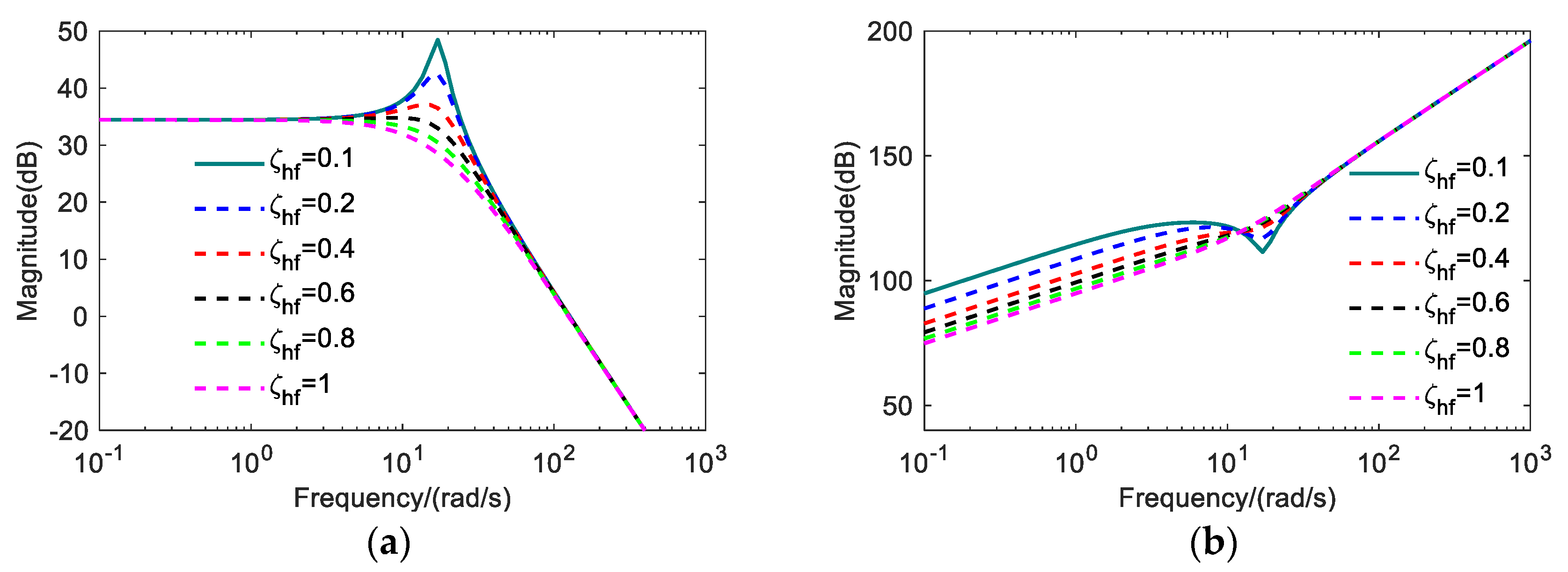
3.2. Calculation and Analysis of Pressure Feedback Correction

The basic equations of Formulas (25)–(27) for Laplace transformations for the tractor hydraulic hitch control system are
{ Q L = K sv I n K c P L Q L = A L s X L + C tL P L + V L β e s P L A L P L = m L s 2 X L + B L s X L + F L
The Laplace of the input current In and the external load force FL acting simultaneously on the lifting cylinder output displacement is
{ X L = K sv A L I n K ce A L 2 ( 1 + V L β e K ce s ) F L s ( s 2 ω h 2 + 2 ζ h ω h s + 1 ) ω h = β e A L 2 m L V L ξ h = K ce 2 A L m L β e V L + B L 2 A L V L m L β e
where ωh is natural frequency of hydraulic hitch system, rad/s; and ξh is the damping ratio of the hydraulic hitch system.
The position control block diagram with pressure feedback correction added according to Formula (29) is shown in Figure 7.
Block-diagram-equivalent transformation is performed on the block shown in Figure 7 to move the feedback access point back, as shown in Figure 8.
The block diagram of the transfer function for the red area in Figure 8 can be written as Formula (30). It can be seen that the pressure feedback correction corresponds to the addition of KaKsvKfKPL to the total flow-pressure coefficient Kce of the hydraulic power element.
P L N = 1 ( K ce + K a K sv K f K P L ) + V L β e s
Let K cf = K ce + K a K sv K f K P L . Ignoring the viscous damping coefficient of the cylinder, the open-loop transfer function of the tractor hydraulic hitch system with pressure feedback correction is as follows:
{ X L = K V I n K V K ce A L 2 ( 1 + V L β e K cf s ) F L s ( s 2 ω hf 2 + 2 ζ hf ω hf s + 1 ) ω hf = β e A L 2 m L V L ζ hf = K cf 2 A L m L β e V L
There is no change in the transfer function of the tractor hydraulic hitch system with pressure feedback and the form without pressure feedback. The open-loop amplification factor and the natural hydraulic frequency have not changed; only the hydraulic damping ratio has changed.
When the electro-hydraulic hitch position control system is used in low-speed field operation, different frequency bandwidth and dynamic response characteristics of the system can be obtained by choosing different damping ratios. A large damping ratio can be used when the electro-hydraulic hitch position control system is used for high-speed transit transportation.
The high-frequency signal of cylinder pressure is filtered and attenuated by increasing system damping to achieve active vibration reduction of the position control system. Pressure feedback is added to the existing electro-hydraulic hitch position control system to achieve vibration reduction control. The dynamic characteristics of the transfer function between the electro-hydraulic lift cylinder pressure PL and the random interference force FL can evaluate this.
According to Formula (31), the closed-loop transfer function of cylinder pressure of the tractor hitch system to interference force is
P L F L = 1 A L ( s + K V ) s 3 ω hf 2 + 2 ξ hf ω hf s 2 + s + K V
The formula for dynamic position stiffness characteristics of the tractor hydraulic hitch damper control system is
F L α ANC = A L 2 K cf s ( s 2 ω hf 2 + 2 ζ hf ω hf s + 1 ) K V ( V L β e K cf s + 1 )
According to Formulas (32) and (33), the amplitude–frequency characteristics of damper control under different dampers can be plotted as shown in Figure 9.
Figure 9a shows that the larger the system damping, the smaller the change in pressure in the lifting cylinder under external interference. This indicates that increasing system damping results in less tractor weight transfer due to external interference. In this case, the tractor hitch system can act as a vibration damper. The cylinder pressure of the tractor hydraulic hitch system with pressure feedback is analyzed for dynamic characteristics of the interference force and dynamic position stiffness.
As can be seen from Figure 9b, the dynamic stiffness of the tractor hydraulic hitch system at low frequencies is reduced by increasing the damping ratio ξhf. During tractor transit, the attached farmer has sufficient ground height to meet the requirement of tractor transit, so the vibration control function of the tractor hydraulic hitch system can be realized with pressure feedback.

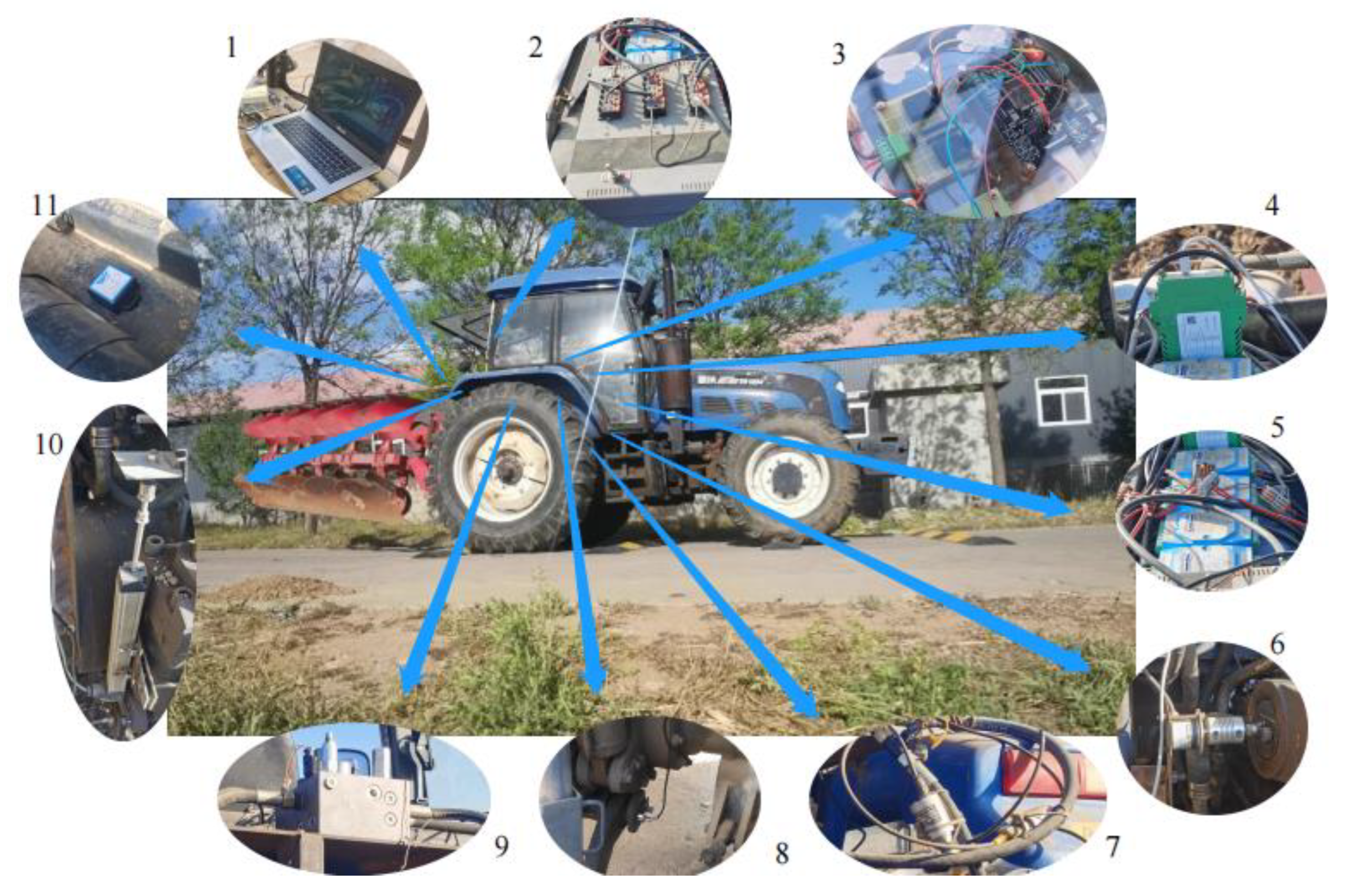
4. Real Tractor Test and Result Analysis

In this section, an experimental study on tractor vibration reduction control based on pressure feedback is carried out. A real test platform is built based on an agricultural tractor, as shown in Figure 10.
The main hardware parameters of the field test platform for the tractor hydraulic hitch control system are shown in Table 1.

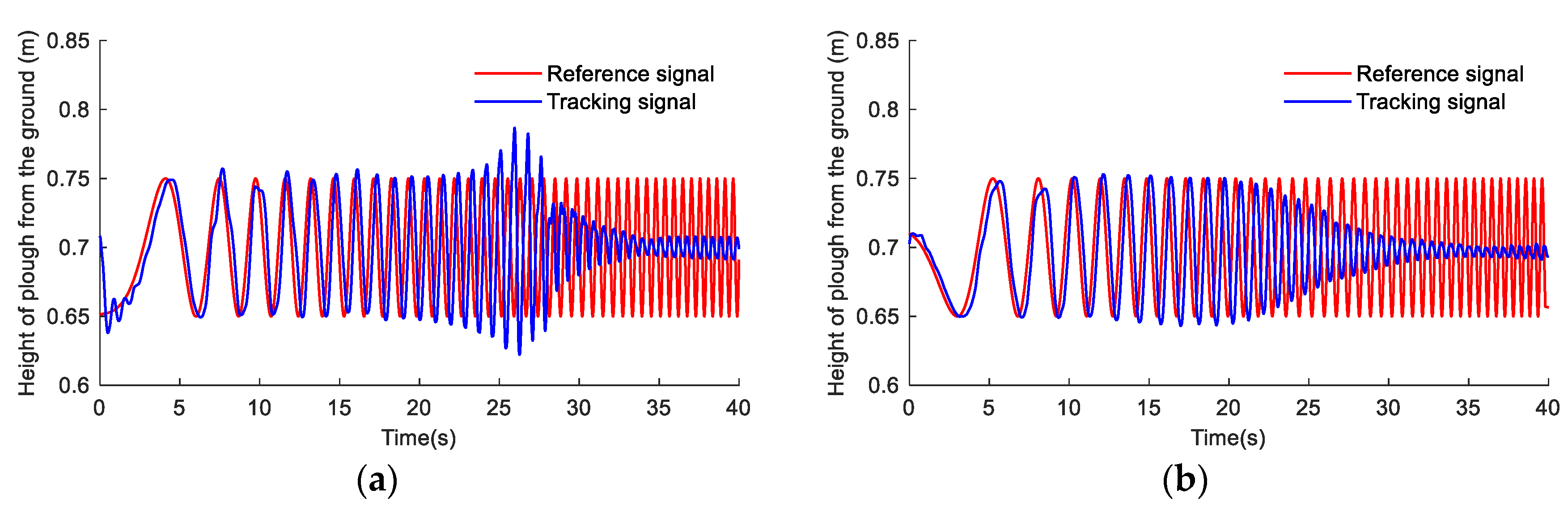
4.1. Sweep Frequency Test of Tractor Hitch System

During the sweep frequency test, the sweep frequency period is 0.01~2 Hz and the amplitude is 0.05 m. In order to obtain the resonance peak value at the natural hydraulic frequency, a more extensive set of controller parameters is taken. In real time, the message information transmitted over the CAN network is monitored and recorded by an upper computer. Sweep frequency tests with the tractor hitch system locked and pressure feedback are performed, and test data for one of the sweep cycles are intercepted, as shown in Figure 11.
It can be seen from Figure 11 that position closed-loop control without pressure feedback occurs in the electro-hydraulic hitch system at about 1.2 Hz of frequency under transit transport conditions. The position closed-loop control with pressure feedback enhances the damping ratio of the hydraulic hitch system under the condition of switching transportation and can suppress the resonance peak at the natural hydraulic frequency, and the resonance peak disappears.

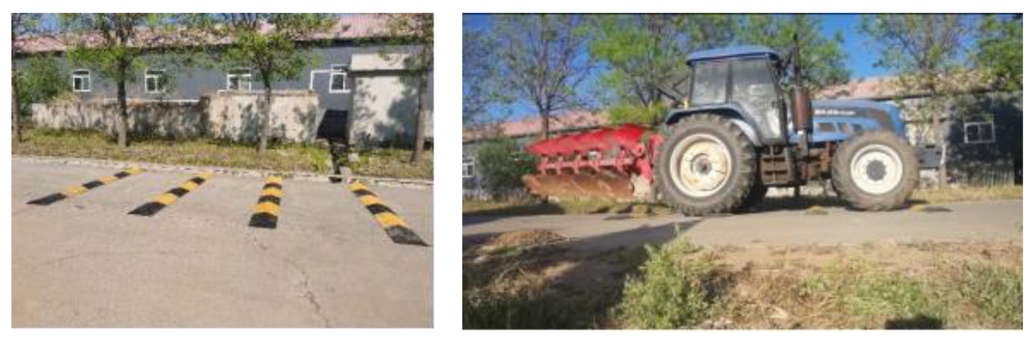
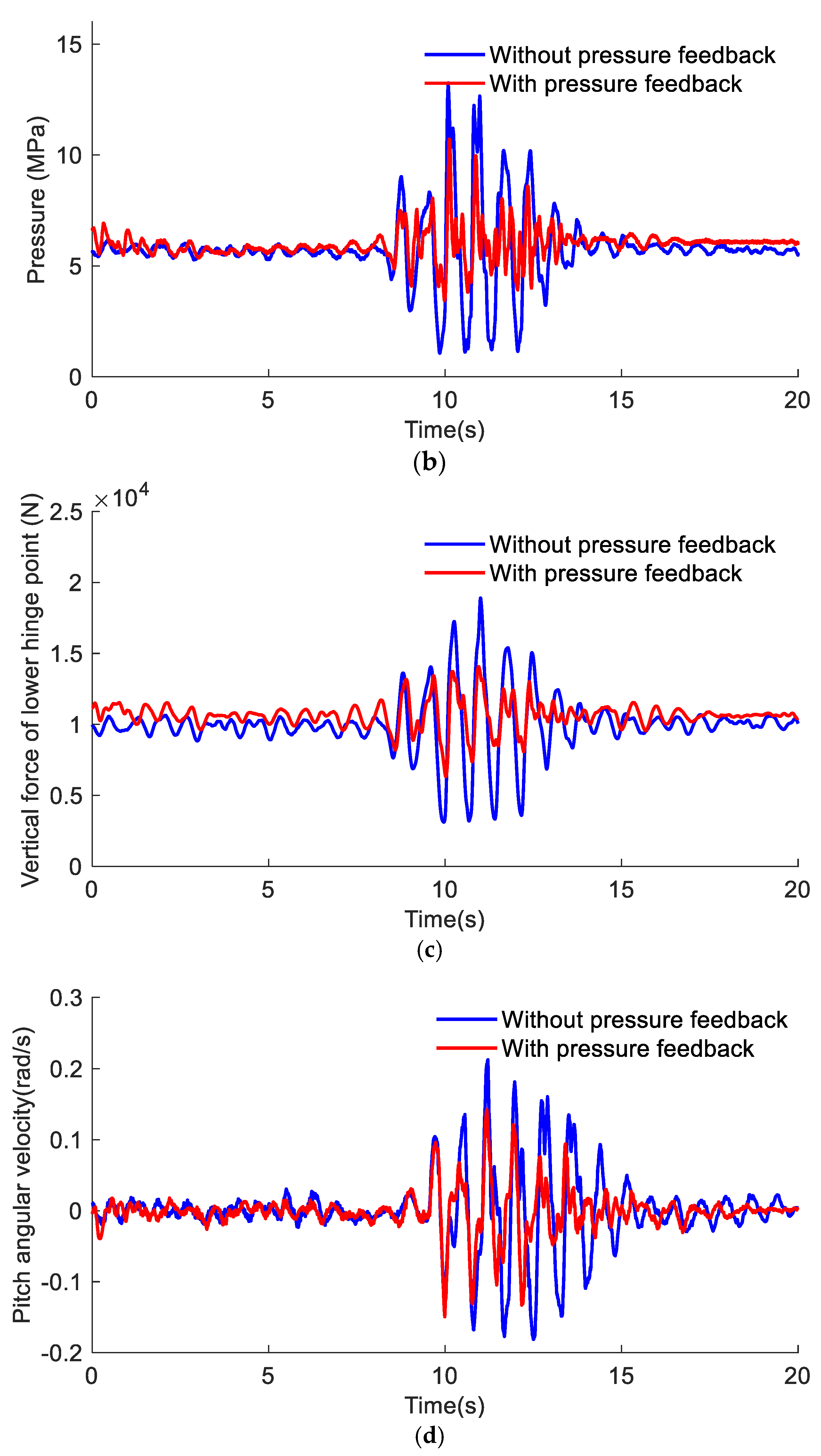
4.2. Passing the Barrier Test

During the test, the farm implements are raised to the specified height, the tractor is maintained at a constant speed of 10 km/s, position control with pressure feedback is carried out through the deceleration belt test, and the deceleration belt test is passed under the state of the tractor rear hitch locking. The deceleration belt ground and test scene are shown in Figure 12. The signal collection has a separate CAN controller that sends data to the bus. The calculation of the electro-hydraulic hitch controller provides the output control signal. In real time, the message information transmitted over the CAN network is monitored and recorded by an upper computer. The cylinder pressure, lifting height, and force pin vertical force of the tractor hitch system for 20 s are intercepted, as shown in Figure 13.
It can be seen from Figure 13 that when the hydraulic cylinder of the tractor hitch system is locked, the safety of the tool can be guaranteed by holding the tool at about 0.65 m through the deceleration belt. From Figure 13a, it can be seen that the control method with pressure feedback for the height of the implement above the ground is slightly higher than the locked state. This is because the use of pressure feedback reduces the load stiffness of the system, and the gravity of the implement itself can cause certain positional errors in the system. However, it is necessary to ensure that the implement has sufficient height and introduces sufficient compensation in the pressure feedback process to overcome the height error caused by the implement’s gravity. The comparison data of vibration reduction control performance are shown in Table 2. The pressure fluctuation range of the hydraulic cylinder is 12.19 MPa, the standard variance is 1.44 MPa, the vertical force fluctuation range of the lower articulation point is 15,780 N, the standard variance is 1869 N, the pitch angle velocity fluctuation range of the tractor is 0.39 rad/s, and the standard variance is 0.0498 rad/s. When using shock absorber control with pressure feedback, the tool can still be maintained at 0.65 m through the deceleration belt to ensure the safety of the tool. The pressure fluctuation range of the hydraulic cylinder is 7.27 MPa, the standard variance is 0.63 MPa, the vertical force fluctuation range of the lower articulation point is 7740 N, and the standard variance is 873 N. The tractor pitch angular velocity range is 0.29 rad/s and the standard variance is 0.0295 rad/s.
It can be found that position control with pressure feedback and locking of the hydraulic cylinder can maintain the height off the ground of farm implements and ensure the safety of farm implements. However, position control with pressure feedback reduces the pressure fluctuation range by 40.3%, the standard variance by 56.25%, the vertical force fluctuation range of the lower articulation point by 51%, the standard variance by 53.3%, the tractor pitch angular velocity range by 25%, and standard variance by 40.76% compared with cylinder locking state. Table 2 shows that the proposed shock absorption control scheme based on pressure feedback of the tractor rear hitch can improve transportation smoothness and handling stability.

5. Conclusions

In order to improve smoothness and safety during tractor transit transportation, a reliable vibration reduction control strategy based on pressure feedback is proposed. The motion of the suspension mechanism was analyzed and a dynamic model of the suspension mechanism was constructed. We calculated the performance of hydraulic systems with different damping ratios and provided a design method for the pressure feedback loop. A real-vehicle test platform was built to verify the effectiveness of the vibration reduction control method based on pressure feedback. The proposed control strategy does not require a force pin sensor. The cost of damping control for the tractor hydraulic hitch was reduced. The following work will further consider the joint-corrected damping control of the upper rod cylinder and the lifting hydraulic pressure. At the same time, we will consider the impact of more factors on the experiment.

Author Contributions

Methodology, C.L., Y.D. and E.M.; Formal analysis, J.G.; Resources, Y.D.; Writing—original draft, L.Y.; Writing—review & editing, X.D. All authors have read and agreed to the published version of the manuscript.

Funding

This research was funded by the National Key Research and Development Program (Project No. 2017YFD0700101), and Jiangsu Ocean University Talent Introduction Research Fund Project (Project No. KQ22018).

Institutional Review Board Statement

This study does not involve the above content.

Data Availability Statement

Not applicable.

Conflicts of Interest

The authors declare no conflict of interest.

References

  1. Hansson, P.A. Optimization of agricultural tractor cab suspension using the evolution method. Comput. Electron. Agric. 1995, 12, 35–49. [Google Scholar] [CrossRef]
  2. Saeys, W.; Mouazen, A.M.; Anthonis, J.; Ramon, H. An Automatic Depth Control System for Online Measurement of Spatial Variation in Soil Compaction, Part 2: Modelling of the Depth Control System. Biosyst. Eng. 2004, 89, 267–280. [Google Scholar] [CrossRef]
  3. Janulevičius, A.; Šarauskis, E.; Čiplienė, A.; Juostas, A. Estimation of farm tractor performance as a function of time efficiency during ploughing in fields of different sizes. Biosyst. Eng. 2019, 179, 80–93. [Google Scholar] [CrossRef]
  4. Liu, C.; Zhao, J.; Gu, J.; Du, Y.; Li, Z.; Zhu, Z.; Mao, E. Pressure control algorithm based on adaptive fuzzy PID with compensation correction for the tractor electronic hydraulic hitch. Appl. Sci. 2020, 10, 3179. [Google Scholar] [CrossRef]
  5. Hung, J.Y.; Gao, W.; Hung, J.C. Variable structure control: A survey. IEEE Trans. Ind. Electron. 1993, 40, 2–22. [Google Scholar] [CrossRef] [Green Version]
  6. Yin, X.J.; Mao, E.R.; Song, Z.H. Effect of Hydraulic Impact on Tractor Body Vibration. Tract. Farm Transp. 2007. Available online: http://en.cnki.com.cn/Article_en/CJFDTotal-TLJY200705011.htm (accessed on 19 July 2023).
  7. Yin, X.J.; Song, Z.H.; Zhu, Z.X.; Xie, B.; Wu, X. New electro-hydraulic control system for tractor. J. Jilin Univ. (Eng. Technol. Ed.) 2008. Available online: http://en.cnki.com.cn/Article_en/CJFDTOTAL-JLGY200803018.htm (accessed on 19 July 2023).
  8. Rexroth Bosch Group. Knowledge Explanation: Hydraulic for Tractor; Bosch Robert AG: Ditzingen, Germany, 2014. [Google Scholar]
  9. Cheng, J.; Chi, R.; Mao, E. Influence of hanging farm implement on vibration of tractor with electro-hydraulic hitch system. Trans. Chin. Soc. Agric. Eng. 2015, 31, 24–32. [Google Scholar]
  10. Cheng, J.; Chi, R.; Lai, Q.; Yang, Y.; Mao, E. Active vibration control of tractor based on electro-hydraulic hitch system. Trans. Chin. Soc. Agric. Eng. 2017, 33, 82–90. [Google Scholar]
  11. Liu, C.; Hua, B.; Du, Y.; Li, Z.; Zhu, Z.; Mao, E. Dynamic Pressure Feedback Correction Method for Tractor Electro Hydraulic Hitch. Trans. Chin. Soc. Agric. Eng. 2020, 51, 7. [Google Scholar]
  12. Zheng, E.; Zhong, X.; Zhu, R.; Xue, J.; Cui, S.; Gao, H.; Lin, X. Investigation into the vibration characteristics of agricultural wheeled tractor-implement system with hydro-pneumatic suspension on the front axle. Biosyst. Eng. 2019, 186, 14–33. [Google Scholar] [CrossRef]
  13. Bell, R.; De Pennington, A. Active compensation of lightly damped electrohydraulic cylinder drives using derivative signals. Proc. Inst. Mech. Eng. 1969, 184, 83–98. [Google Scholar] [CrossRef]
  14. Krus, P.; Palmberg, J. Damping of mobile systems in machines with high inertia loads. Proc. JFPS Int. Symp. Fluid Power 1989, 1989, 63–70. [Google Scholar] [CrossRef] [Green Version]
  15. Rahmfeld, R.; Ivantysynova, M. An Overview about Active Oscillation Damping of Mobile Machine Structure. Int. J. Fluid Power 2004, 5, 5–24. [Google Scholar] [CrossRef]
  16. Andersen, T.O.; Hansen, M.R.; Pedersen, H.C.; Conrad, F. Comparison of Linear Controllers for A. In Proceedings of the JFPS International Symposium on Fluid Power, Tsukuba, Japan, 5–10 November 2005. [Google Scholar]
  17. Zæv, E.; Rath, G.; Kargl, H. Energy Efficient Active Vibration Damping; Linköping University Electronic Press: Linköping, Sweden, 2013; pp. 355–364. [Google Scholar]
  18. Watton, J. Fundamentals of Fluid Power Control: Steady-State Characteristics of Circuit Components; Cambridge University Press: Cambridge, MA, USA, 2009. [Google Scholar]
  19. Axin, M.; Krus, P. Design Rules for High Damping in Mobile Hydraulic Systems; Linköping University Electronic Press: Linköping, Sweden, 2013; pp. 13–20. [Google Scholar]
  20. Axin, M.; Palmberg, J.; Krus, P. Optimized damping in cylinder drives using the meter-out orifice: Design and experimental verification. In Proceedings of the 8th International Fluid Power Conference, Dresden, Germany, 26–28 March 2012; pp. 579–591. [Google Scholar]
  21. Axin, M. Mobile Working Hydraulic System Dynamics; Linköping University Electronic Press: Linköping, Sweden, 2015; Volume 1697. [Google Scholar]
  22. Lantto, B.; Krus, P.; Palmberg, J.O. Dynamic Properties of Load-Sensing Systems with Interacting Complex Mechanical Loads. J. Dyn. Syst. Meas. Control. 1993, 115, 525. [Google Scholar] [CrossRef]
  23. Pedersen, H.C.; Andersen, T.O. Pressure Feedback in Fluid Power Systems—Active Damping Explained and Exemplified. IEEE Trans. Control. Syst. Technol. 2017, 26, 102–113. [Google Scholar] [CrossRef]
Figure 1. Motion sketch of tractor hitch mechanism.
Agriculture 13 01546 g001
Figure 2. Force analysis of farm tools.
Agriculture 13 01546 g002
Figure 3. Force analysis on the pull-down bar.
Agriculture 13 01546 g003
Figure 4. Force analysis on the lifting arm.
Agriculture 13 01546 g004
Figure 5. Principle of tractor damping control based on pressure feedback.
Agriculture 13 01546 g005
Figure 6. Schematic diagram of the electro-hydraulic hitch valve. 1. Constant-differential pressure-reducing valve. 2, 4. Proportional directional valve. 3. Safety valve. 5. Single-acting hydraulic cylinder.
Agriculture 13 01546 g006
Figure 7. Position control block diagram with pressure feedback correction, where Kf is the pressure feedback coefficient, k α ANC is the position feedback coefficient, Ka is the amplifier gain, U R α ANC and U α ANC are the analog voltage of the system command and the feedback voltage of the system, respectively, E is the bias voltage of the system input and output.
Agriculture 13 01546 g007
Figure 8. Equivalent-position control block diagram with pressure feedback correction, where N is the input of the pressure feedback stage.
Agriculture 13 01546 g008
Figure 9. Amplitude−frequency characteristics of vibration reduction control of electro−hydraulic hitch: (a) amplitude−frequency characteristics of pressure and interference force; (b) amplitude−frequency characteristics of dynamic stiffness of position control system.
Agriculture 13 01546 g009
Figure 10. Field test stand for tractor hydraulic hitch tool damping control system. 1—upper computer; 2—power supply; 3—controller; 4—proportional amplifier; 5—CAN series module; 6—lift arm angle sensor; 7—pressure sensor; 8—force-measuring pin; 9—electro-hydraulic proportional valve; 10—displacement sensor; 11—pitch angular speed sensor.
Agriculture 13 01546 g010
Figure 11. Sweep frequency test of 0.01–2 Hz under transit transport conditions: (a) sweep test without pressure feedback; (b) sweep test with pressure feedback.
Agriculture 13 01546 g011
Figure 12. Vibration control pavement and test scene.
Agriculture 13 01546 g012
Figure 13. Test curve of tractor damping control: (a) agricultural implements raised off−ground height; (b) hydraulic cylinder pressure of hitch system; (c) vertical force at lower articulation point; (d) tractor pitch angular speed.
Agriculture 13 01546 g013aAgriculture 13 01546 g013b
Table 1. Hardware parameter table of electro-hydraulic hitch test platform.
TypeModelModelOperating Parameters
Force-measuring pinYZC-9Ocean Sensing System Engineering Co., Ltd., Bengbu, ChinaWorking voltage: 24 V, output: −10 V~10 V analog signal, customized measuring range: −50,000 N~50,000 N, comprehensive error: <0.05
Displacement sensorLWH-0250Novotechnik, Ostfildern, GermanyWorking voltage: 12 V, output: 0~10 V analog signal, measuring range: 0–250 mm, resolution: >0.01 mm
Pressure sensorMIK-P300Hangzhou Mico Sensing Technology Co., Ltd., Hangzhou, ChinaWorking voltage: 24 V, output: 0–5 V analog signal, accuracy: 12 bits, customized range: 0–20 MPa
ControllerTMS320F28335Texas Instruments (TI), Dallas, TX, USAWorking voltage: 3.3 V, with strong signal processing and communication capability, two ways to enhance eCAN, support floating point operation, and support external serial communication
Proportional amplifierAEG-12A-02Qiaocun Technology Co., Ltd., Chengdu, ChinaWorking voltage: 24 V, CAN bus input interface, maximum output current adjustable: 0.2~3 A
Table 2. Comparison of damping control performance.
Pressure of the Hydraulic
Cylinder (MPa)
Vertical Force of the Lower Articulation Point (N)Pitch Angular Velocity (rad/s)
RangeStandardRangeStandardRangeStandard
locking of hydraulic cylinder12.191.4415,78018690.390.0498
position control with pressure feedback7.270.6377408730.290.0295
Disclaimer/Publisher’s Note: The statements, opinions and data contained in all publications are solely those of the individual author(s) and contributor(s) and not of MDPI and/or the editor(s). MDPI and/or the editor(s) disclaim responsibility for any injury to people or property resulting from any ideas, methods, instructions or products referred to in the content.

