Article

Design and Field Test of a Leaping Type Soil-Covering Device on Plastic Film

1
College of Mechano-Electronic Engineering, Gansu Agricultural University, Lanzhou 730070, China
2
Gansu Agricultural Mechanization Technology Extension Station, Lanzhou 730046, China
*
Author to whom correspondence should be addressed.
Agriculture 2023, 13(9), 1680; https://doi.org/10.3390/agriculture13091680
Submission received: 13 July 2023 / Revised: 20 August 2023 / Accepted: 22 August 2023 / Published: 25 August 2023
(This article belongs to the Section Agricultural Technology)

Abstract

:
This paper presents the designs and calculations of a leaping type soil-covering device for potato cultivation. The device is based on the full-film mulching cultivation mode, where the seed rows are covered with soil. The working principle of the leaping type soil-covering device was analyzed and the core structural parameters were determined. In order to search for a reasonable rotation speed of the screw conveyor, the soil-covering process of leaping type soil-covering device is simulated based on the EDEM software. Through single factor simulation experiments, relationship between the width and thickness of covering soil and the rotation speed of the screw conveyor was studied. The optimal values obtained were the scraper height of 60 mm and the screw conveyor rotation speed of 169 r/min. Based on the quadratic function fitting, the relationship between the length of the soil cover and the position of the seedling belt was determined. With the optimization objective of the seedling belt misalignment rate, the length of the soil cover was determined to be 417 mm. A prototype of the device was manufactured and tested in the field. The field test showed that the qualified rate of the thickness of the seeded soil cover was 92%, the qualified rate of covering soil thickness was 91%, the dislocation rate between the seeding row with covering soil and the seedling belt was 5%, and the damage degree of plastic film was 49.2 mm/m2. These results indicate that the designed potato planter with leaping type soil-covering device meets accepted agronomical requirements of potato planters and film-mulching planters. The natural emergence rate of potato seedlings reached 92% and the seedling burning rate was 7%.

1. Introduction

As the fourth largest grain crop in China, potato planting has increased significantly in recent years. This is due to the high yield and stability of potatoes, as well as their wide adaptability and full nutrient content. Potatoes play a significant role in ensuring China’s food security and promoting agricultural production and income growth [1,2,3,4].
The arid areas in Northwest China account for about 1/4 of China’s land area [5]. The northwest planting area is an important part of this region, and it receives very little precipitation. Precipitation in this area is mainly in the form of micro-bursts and ineffective rainfall [6].
To address this challenge [7,8,9], agricultural researchers in the northwest arid region have proposed an agricultural model that uses whole-area plastic mulch and soil covering—see Figure 1 and reference [10]. Studies have shown [11,12,13,14] that potato sprouts can break the plastic film, if the film is covered with a layer of soil after sowing. The sprouts will not disperse if they are not exposed to the sun light during germination (see Figure 1a), and the seedlings will break the film and naturally emerge (see Figure 1b,c), helped by the soil layer pressure and by the natural upward action of the sprouts. This model (see Figure 1d) requires the development of highly adaptive, high-efficiency, and high-quality potato mechanized sowing equipment. The equipment should be able to perform the following:
Sow potatoes at a consistent depth and spacing.
Apply plastic mulch evenly.
Cover the planting rows with soil.
Locate a miniature rainwater collecting groove in the middle of the potato ridge.
The development of this equipment will help to improve potato production in China’s northern arid region. It will also help to ensure food security and promote agricultural production and income growth.
Current research on film-mulching devices focuses on semi-film planting methods. These methods use a plow, disc, drum, or rotary tiller to move soil from the side of the film and transport it laterally. This leaves exposed soil between adjacent films [15]. Zhang [16] designed a weeding cultivator and hilling machine for whole-film mulch planting. It is powered by an electric motor and has an adjustable blade that can be used for different ridge widths and soil-raising heights. The machine can loosen soil and weed and raise soil in one operation. Li [17] and other researchers developed a sugarcane horizontal planter with a soil-covering disc at the rear. As the planter moves forward, the disc rotates and the soil on the disc surface flows to the center of the ditch. This completes the soil-covering operation. The core parameters of the disc type soil-covering device, such as the disc diameter and the distance between the left and right disc centers, were determined. The influence of the disc depth and the included angle between the disc and the forward direction of the planter on the soil-covering thickness was also analyzed. Zheng [18] and others found that the traditional soil-covering disc was difficult to adjust on slopes due to the difference In soil volume on either side of the disc. This made It difficult to adapt to different operating environments, which affected the effectiveness of soil covering. They designed a differential adjustment and linkage soil-covering device to improve the effectiveness of soil covering. Zhang [19] designed a soil-covering device that places soil in the center of the plastic film surface. When the soil-covering device moves forward under the traction of the film-mulching seeder, it drives the soil-covering roller to roll forward. The soil inside the soil-covering roller is transported to the middle under the action of the soil guide plate inside the soil-covering roller, and is leaked out through the soil leakage hole to cover the seeding belt. Large soil blocks, large stones, and crop straws are discharged from the impurity discharge hole. The potato soil loader [20] (model 2TD-S2) uses a rotary tillage lifting mechanism that can complete the operation procedures of ridge scarifying and film soil covering at once. The soil is rotated by the rotary tillage knife with the cooperation of the soil guide covering and covering scraper to cover soil on the mulching film. This method is only applicable to full film soil-covering planting patterns.
Traditional mechanized film mulching planting and soil-covering technology uses a principle of taking soil from the side of the film and transporting it laterally. This requires an exposed soil belt between adjacent films to allow the soil-covering mechanism to obtain soil and the planter to walk without damaging the film. However, this approach does not meet the agronomic requirements of film mulching and soil covering the entire seeding belt. Additionally, the quality of soil covering is only determined by empirical formulas, and the dislocation rate of planting lines and seedling belts is high. The discrete element method (DEM) proposed by A. Cundall is an important method for analyzing particle motion laws and the interaction mechanism between particles and mechanical components [21]. The popularization of discrete element method has greatly improved the efficiency of mechanical component design.
To address these challenges, this paper designed and optimized a leaping type soil-covering device on plastic film based on the discrete element method (DEM). Field tests were also conducted.

2. Materials and Methods

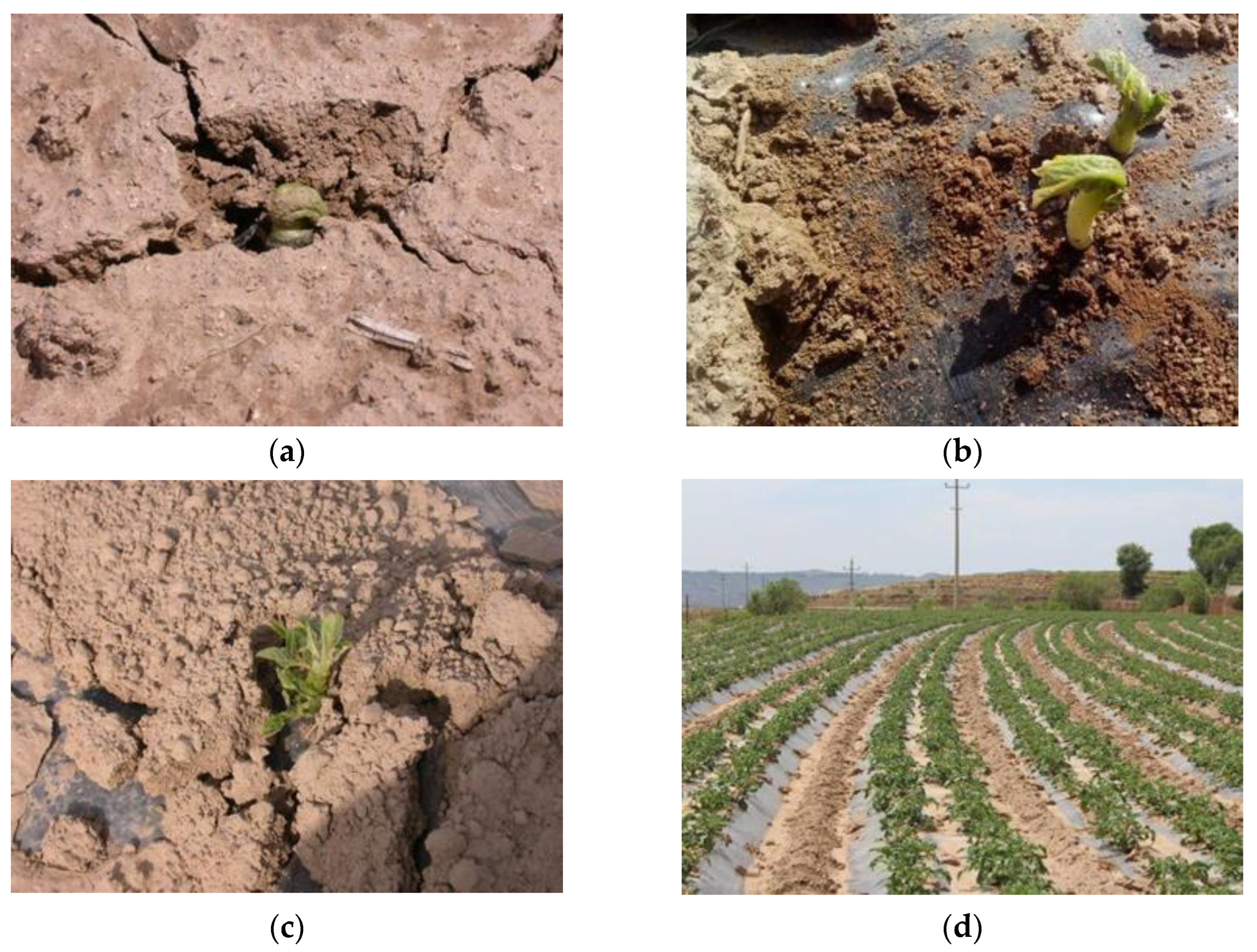
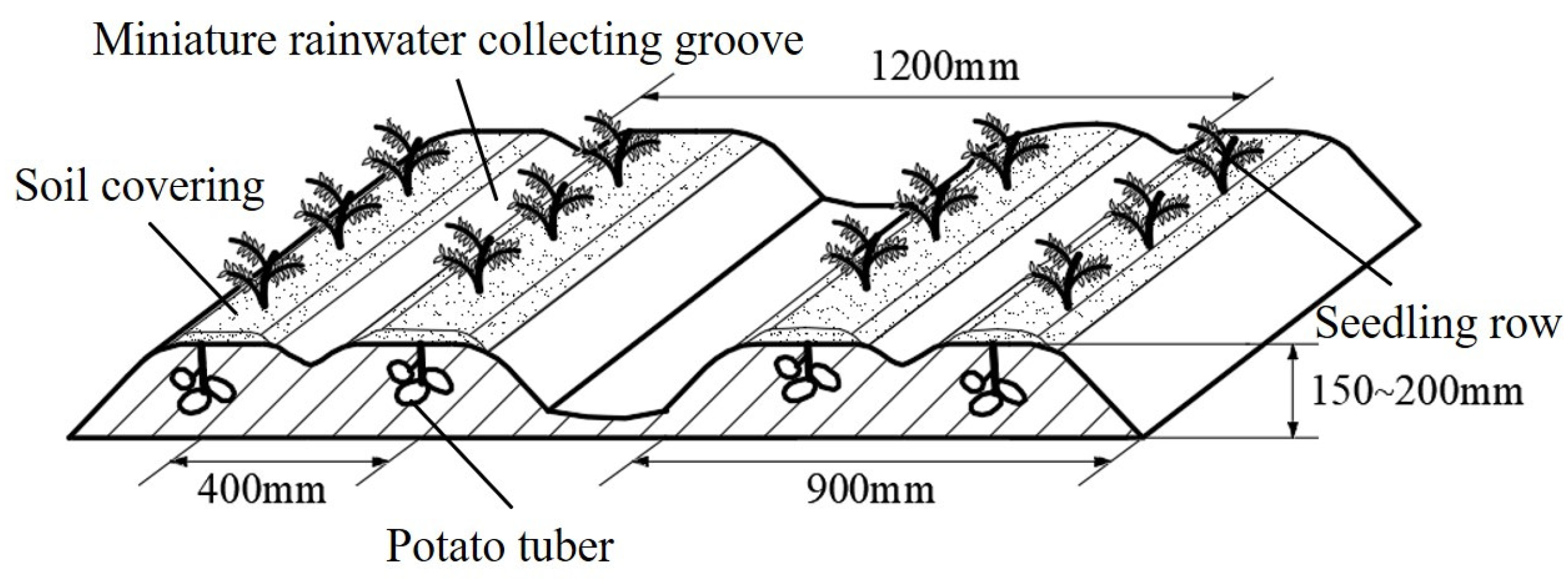
2.1. Agronomic Requirements

Full plastic film mulching and soil covering at the seeding row has become a common practice in Northwest China due to the region’s drought, low rainfall, and low ground temperatures [22]. Figure 2 shows the ridge shape of this potato planting pattern. The ridge is 900 mm wide, the seed rows are spaced 400 mm apart, the ridge height is 150–200 mm, the adjacent ridges are spaced 1200 mm apart, and the width and thickness of the covering soil on the seed row are 200 mm and 30–50 mm, respectively. A black film with a width of 1200 mm and a thickness of 0.01 mm is generally used because it has a good grass suppression effect. To prevent the soil covering the seedling row from hardening, a miniature rainwater collecting groove is located in the middle of the potato ridge, and seep holes are drilled in the plastic film covering the miniature rainwater collecting groove.

2.2. Overall Structure and Working Principle

The potato full-film mulching and soil-covering cultivation prototype is mainly composed of a body frame, ground wheels, a fertilization device, a seeding device, a shaping device, a film-mulching device, and the leaping type soil-covering device (as shown in Figure 3). When the potato full-film-mulching planter is operating, the fertilization device, the seeding device, the leaping type soil-lifting device, the shaping device, the film-mulching device, and the leaping type soil-covering device all work simultaneously to fertilize, sow, ridge, shape, and cover the soil with plastic film, and for covering soil at the seeding row and film edge.

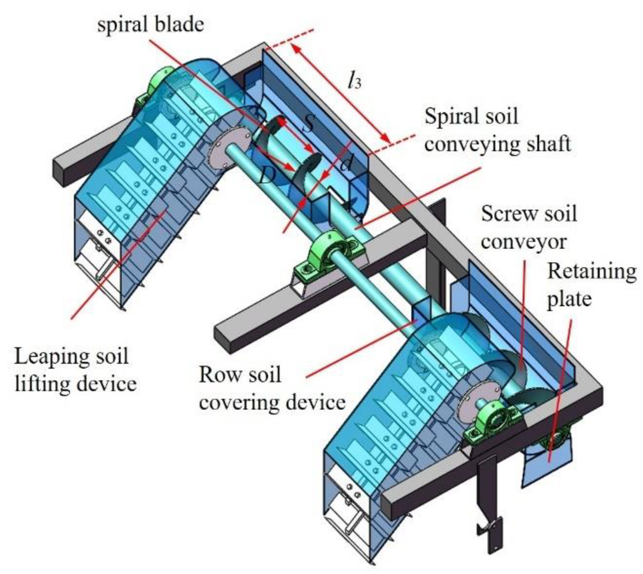
2.3. Structure of the Leaping Type Soil-Covering Device

The leaping type soil-covering device is symmetrically arranged and consists of two main parts: the leaping type soil-lifting device and the lateral soil-covering device. The leaping type soil-lifting device is connected to the body frame through the lifting depth adjuster. It includes the following components: trenching shovel, lifting belt, lifting belt tension mechanism, lifting depth adjuster, driving wheel, and driven wheel. The lateral soil-covering device is composed of the following components: screw soil conveyor, row soil-covering device, and spiral soil conveying shaft (see Figure 4).

2.4. Working Principle of the Leaping Type Soil-Covering Device

The leaping type soil-covering device works by first using a trenching shovel to lift soil. The soil is then transported to a leaping soil-lifting device, which transports it to a film-mulching device and then to a lateral soil-covering device. Some of the soil falls on the surface of the film edge to cover it, and the rest of the soil is transported to the seed row by a screw soil conveyor. This completes the seed row soil-covering work (see Figure 4).

2.5. Leaping Soil-Lifting Device

Scraper conveyors are commonly used in agricultural machinery equipment to transport grain, broken straws, roots, and powders. The most common type of scraper conveyor is the under-scraper elevator, which scrapes and lifts material along the inner surface of the conveying trough.
To shorten the length of the conveyor and ensure timely unloading of soil, the leaping-type soil-covering device uses the “leaping over the top” conveying pattern, which is based on the working principle of the scraper conveyor.

2.5.1. Analysis of Scraper Movement of Leaping Soil-Lifting Device

The movement of the lowest point of the scraper on the leaping soil-lifting device is composed of two movements: the constant rotation of the lowest point of the scraper around the center of the driven wheel, and the forward movement of the planter during operation. As shown in Figure 5, the displacement Formula (1) for the lowest point of the scraper is established. This formula shows that when other planter parameters are fixed, the smaller the ratio of the linear velocity of the conveyor belt to the forward velocity of the planter, the greater the soil-lifting capacity of the leaping soil-lifting device. According to related literature [23], the linear velocity of the conveyor belt of the leaping soil-lifting device is set to be 1.5 m/s, and the forward velocity of the planter is 0.6 m/s.
x = R θ v v + R + h s i n θ y = R + h 1 c o s θ         γ < θ < π γ  
where x is the horizontal displacement of the lowest point of the scraper (m), y is the vertical displacement of the lowest point of the scraper (m), R is the radius of driven wheel (m), h is the height of the scraper (m), v′ is the belt speed (m/s), v is the planter forward velocity, θ is the turning angle of the scraper (°), and γ is the included angle between the lifting belt and the horizontal plane (°).

2.5.2. Soil Delivery Capacity of Leaping Soil-Lifting Device

When cultivating potatoes using the full-film mulching and seed row soil-covering method, each ridge must be covered with four soil belts. Two belts are used to press down the edge of the film, and the other two are pressed onto the film surface above the seed row, which allows the potato seedlings to break through the film and emerge.
The width of the soil belt on the edge of the film is 70 mm, and the thickness is between 30 and 50 mm. The width of the seed row is 200 mm, and the thickness of the soil covering the seed row is also between 30 to 50 mm. The main soil types are calcareous soil and yellow soil, and the bulk density is 1300 kg/m3 [15].
The soil transport rate Q of the leaping soil-lifting device ranges from 22,744.8 to 37,908 kg/h and can be calculated using the following formula:
Q = 3600 γ 1 l 1 h 1 v + γ 1 l 2 h 2 v
where h1 is the thickness of covering soil on film edge (m), l1 is the width of covering soil on film edge (m), h2 is the thickness of covering soil on seed row (m), l2 is the width of covering soil on seeding row (m), and γ1 is bulk density of soil (kg/m3).
The leaping soil-lifting device collects soil before the film is mulched and then transports it onto the surface of the film after the film is mulched (see Figure 5). The device is composed of a trenching shovel, driven wheel, scraper, and lifting belt.
The capacity of the soil-lifting device to carry soil is mainly related to the width, height of the scraper, and the linear velocity of the lifting belt. If the linear velocity of the lifting belt is too high, it could blow away soil particles, which is not conducive to the scraping of soil. But if the linear velocity is too low, the operation efficiency would be affected.
According to existing research [23], the linear velocity of the lifting belt should be v′ = 1.5 m/s, the installation angle of the soil-lifting device should be γ = 35°, the conveying efficiency φ1 = 0.86, and the inclined conveying coefficient k = 0.4. The height of the leaping soil-lifting device can be calculated with the following formula:
h = Q 3600 B γ 1 v k φ 1
where B is the width of the scraper (m), and Q is the soil transport rate in kg/h. With the above values and for Q = 22,744.8 kg/h, installation spacing of the scraper e = 100 mm and the width of scraper B = 150 mm, and the scraper height equals 60 mm, which meets the design requirements of the planter.

2.5.3. Depth of Soil Lifting

In order to ensure the amount of covering soil on the plastic film, the following inequality must hold true:
H B l 1 h 1 + l 2 h 2
where H is the depth of soil lifting (m). The depth of lifting must be greater than 54 mm, and at the same time, in order to ensure the required height of the ridge, the depth of lifting is selected as 150 mm according to the agricultural requirements of potato planting patten.

2.6. Lateral Soil-Covering Device

The cultivation pattern of full-film mulching and seed row covering requires that the soil must be obtained from the side of film and be transported transversely to seed row. The existing lateral soil conveying equipment is roller type and spiral type [24,25,26]. Because the spiral blade and soil-covering device move in relation to one another when the spiral lateral soil conveying device is operating, the soil crushing capacity of the roller type is lower than that of the screw type. Therefore, the screw lateral soil conveying device is used to cover soil on the edge of plastic film and seed row (see Figure 6). The lateral soil conveying device is mainly composed of screw soil conveying device and seeding row soil-covering device.

2.6.1. Screw Soil Conveyor Device

The theoretical soil transportation efficiency of the screw soil conveyor within one pitch is expressed as Formula (5) [27]:
Q t = π 4 D 2 d 2 S n
where Qt is the theoretical soil transportation efficiency (m3/main), n is the speed of screw conveyor shaft (rpm), D is the diameter of spiral blade (m), S is the pitch (m), and d is the diameter of spiral soil conveying shaft (m).
When the screw soil conveyor device works, the actual soil delivery volume within one pitch cannot reach the theoretical soil delivery volume, so it will cause the loss of volumetric efficiency, which is expressed as Formula (6):
η V = Q a Q t
where ηV is the volume efficiency, and Qa is the actual soil transportation efficiency, both in %. Volumetric efficiency can be further calculated with the following formula:
η V = f f r , D , d , S , f γ 2 , μ 1 , μ , n S g
where μ1 is the friction coefficient between soil particles, μ is coefficient of friction between soil particles and spiral surface, g is the acceleration of gravity, and γ2 is the inclination of auger.
The diameter D of spiral blade is 150 mm, the pitch is 150 mm, and the diameter d of spiral soil conveying shaft is 45 mm. The above Formula (6) shows that the volumetric efficiency of the screw soil conveyor device is due to the multiple functions of the structural parameters of the screw soil conveyor device, such as rotation speed of the spiral soil conveying shaft, other operating parameters, and the physical parameters of the soil. Therefore, it is extremely complex to determine the volumetric efficiency of the screw conveyor. Rehkugler and Boyd [27] established the mathematical model of the volumetric efficiency of the screw conveyor for wheat, oats, and shelled corn through the above Formula (7) combined with the field test. However, the properties of the soil in the northwest arid area are different from those of the above materials, which is not suitable for the theoretical calculation of the screw soil conveyor device. At the same time, the above formula shows that the rotation speed of the spiral soil conveying shaft affects the amount of soil covered, and then, the width and thickness of the soil covered is also affected. Therefore, the limited conditions such as the width and thickness of the seed row covering must be taken into consideration in order to determine the rotation speed of the spiral soil conveying shaft.

2.6.2. Seeding Row Soil-Covering Device

The soil particles are transported to the driven wheel by the scraper and thrown into lateral soil-covering device under the action of the scraper and the retaining plate (see Figure 7). The axial cross section of the soil falling on the lateral soil conveying device forms an area. When the β is less than 90°, the soil section area inside the lateral soil conveying device is the difference between the sector area corresponding to the sector and the triangle area corresponding to the sector. When β is greater than 90°, the soil section area is the sum of the sector area corresponding to the sector and the triangle area corresponding to the sector. If the amount of covered soil produced by the rotation of the spiral soil conveying shaft for one cycle is equal to the amount of soil transported within one pitch, the thickness of covering soil inside lateral soil conveying device after filling is b. The value should satisfy the following Formula (8).
S ( β r 2 360 r 2 sin β cos β ) = l h 2 v 60 n       β 90     S ( β r 2 360 + r 2 sin β cos β ) = l h 2 v 60 n       β 90
where l is the length of covered soil when the screw soil conveying device rotates for one cycle (m), and r is the radius of covered soil on seed row (m).
Under the action of the sparid blade, the soil particles move along the axial direction and rotate in the circumferential direction. Because of the friction force of the spiral blade against the soil particles, the velocity direction of the soil particles is offset by angle Φ from the normal direction of the spiral blade at this point. To analyze the axial velocity characteristics of soil particles, the absolute velocity of soil particles (see Equation (8)) is orthogonally decomposed into axial velocity V1 and circumferential velocity V2 [28], as shown in Figure 8.
V 1 = S n 60 c o s 2 α 1 μ S 2 π r 1 V 2 = S n 60 c o s 2 α μ S 2 π r 1 v  
where r1 is spiral blade radius corresponding to the thickness of soil inside the row soil-covering device (m), V2 is the axial velocity of soil particles (m/s), V1 is the circumferential velocity of soil particles (m/s), α is the spiral rise angle of the pusher, and Φ is the friction angle.
If the influencing power of soil particles, spiral blades, and retaining plate on the soil particles is ignored, then the soil particles are only affected by gravity. Therefore, the movement of soil particles inside row soil-covering device are simplified as horizontal projectile motion. According to the theory of horizontal projectile motion, when β ≥ 90°, the width of covering soil on seeding row l2 should satisfy the Formula (10):
l 2 = S n 60 c o s 2 α 1 μ S 2 π r 1 2 r 1 cos β + h 1 g 1 μ S π D 2 h 1 g
When β ≥ 90°, the width of seeding row soil covering l2 should satisfy the Formula (11):
l 2 = S n 60 c o s 2 α 1 μ S 2 π r 1 2 r 1 + cos β + h 1 g 1 μ S π D 2 h 1 g
Therefore, the width of covering soil is related to the parameters such as the rotation speed of the screw soil conveyor, the pitch, and the vertical distance between the soil on seed sow and the film.

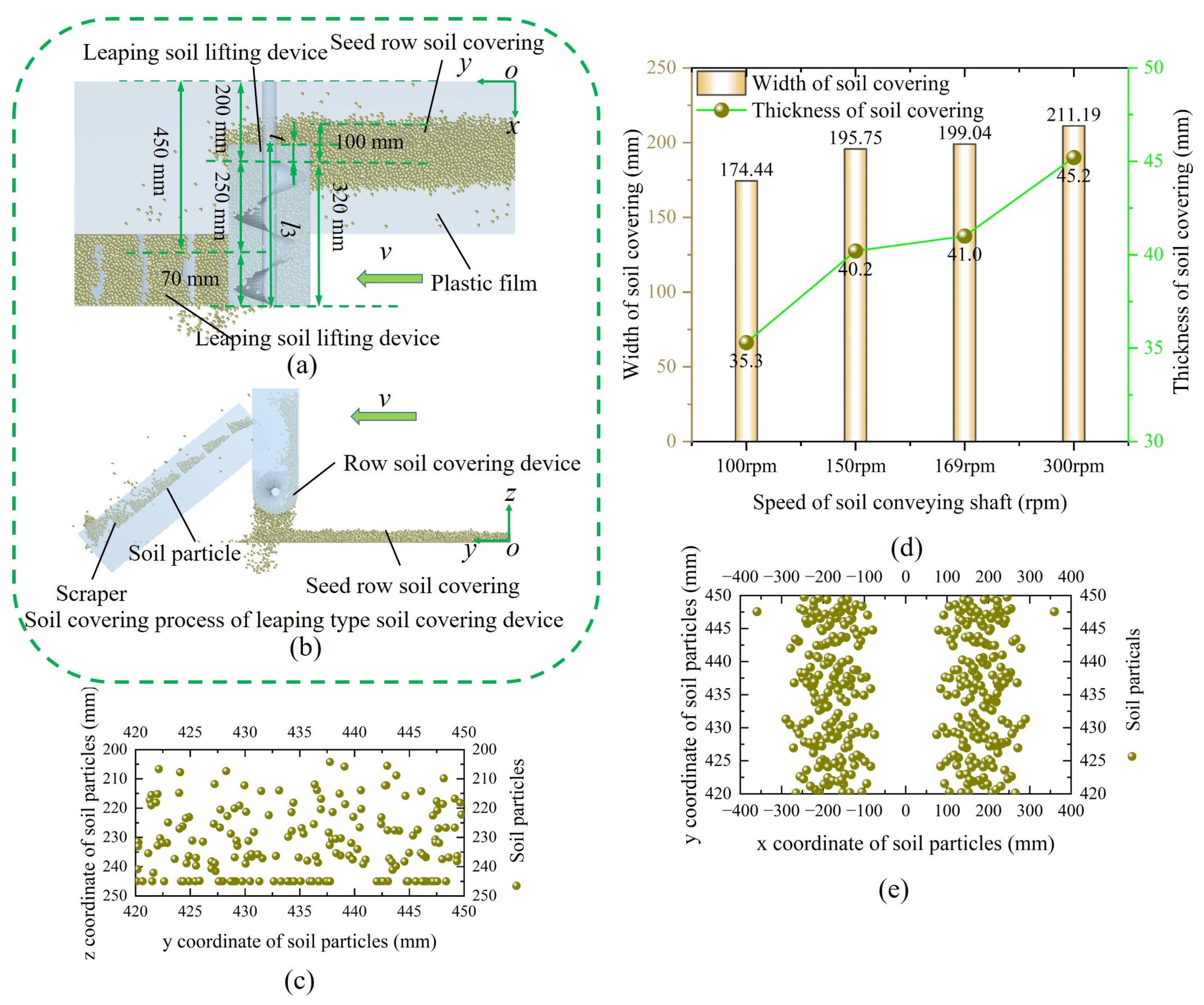
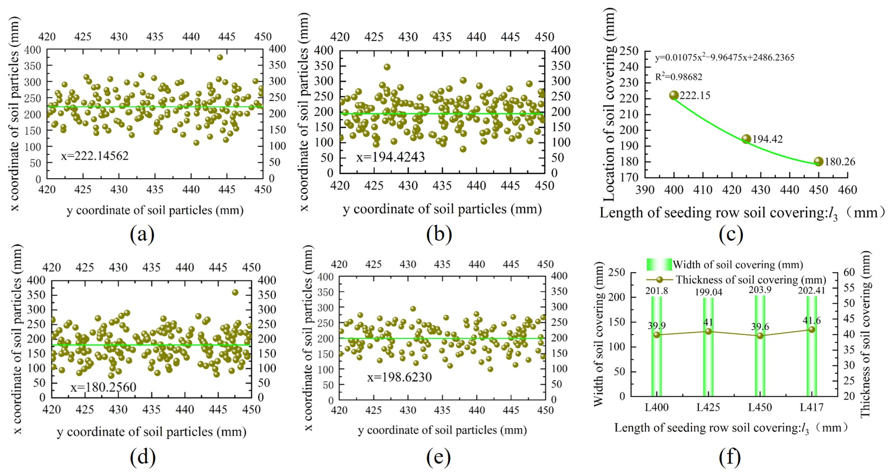
2.6.3. Cover Thickness and Width of Seeding Row

To ensure the stability of covering soil on the plastic film, it is required that the soil conveying efficiency Q of the leaping soil-lifting device should be matched to the soil conveying efficiency Qt of the screw soil conveyor device. The complexity of the soil volume efficiency makes the theoretical calculation of the soil conveying efficiency of the screw soil conveyor device difficult. The above theoretical analysis shows that the width, thickness of covering soil, and volume efficiency of the screw soil conveyor device are related to the rotation speed of the screw conveyor shaft. Therefore, in order to search for a reasonable rotation speed of the screw conveyer, the soil-covering process of leaping type soil-covering device is simulated based on the EDEM software.

Simulation Parameter Settings

The simulation parameters (see Table 1) are set based on reference [23], and the motion of a single scraper is divided into four movements, namely, linear motion along the scraper motion direction, rotational motion around the driving wheel, linear motion along the scraper motion direction, and rotational motion around the driven wheel. The rack is set to be fixed, and the movement of the film is set to be opposite to the actual movement of the unit. The simulation time is set to 4 seconds.

The Result of Soil-Covering Simulation

The simulation results are shown in Figure 9a–e. The results show that when the planter’s movement forward velocity is 0.6 m/s, the diameter of the spiral blade is 150 mm, the diameter of the soil conveying shaft is 45 mm, the half diameter of the row soil-covering device is 160 mm, the vertical distance of the seed row soil-covering device from the plastic film is 200 mm, and other operating parameters are fixed. As the rotation speed of screw conveyor changes from 100 to 300 rpm, the width and thickness of covering soil on seeding row increase (see Figure 9d). When the rotation speed of the screw conveyor is 169 rpm, the width of the covering soil on the seeding row is 199.04 mm, and the thickness of the covering soil on the seeding row is 41 mm, which meets the requirements of soil covering on the seeding row. Therefore, the rotation speed of the screw conveyor shaft is 169 rpm, which is selected as the operation parameter of the leaping type soil-covering device.

2.6.4. Analysis of the Dislocation Rate between Covering Soil on Seeding Row and Seedling Belt
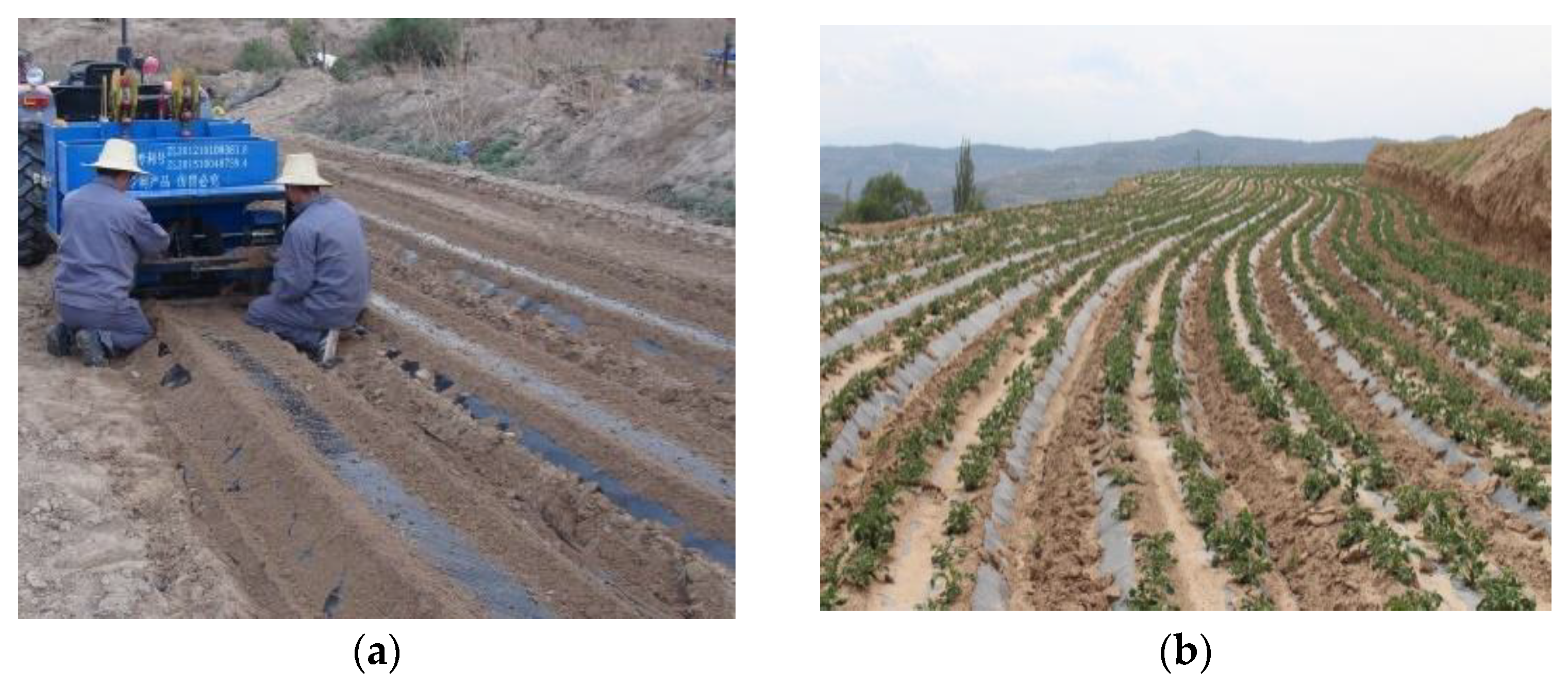
The length of the seeding row soil-covering device greatly affects the position of the seeding row soil covering and dislocation rate between the seeding row covering and seedling belt. According to the agronomic requirements, the width at the bottom of the potato ridge is 900 mm, the width of the covering soil on the film side of the single ridge is 70 mm, and the horizontal distance of the covering soil on the seeding row is 200 mm (see Figure 2), and the critical maximum length of seeding row soil-covering device is 420 mm. The critical maximum length is selected based on the criteria that the inner boundary of the seeding row soil covering and the inner projection of the seeding row soil-covering device on the xoy plane are collinear (see Figure 9a,b). The t refers to the horizontal distance between the inner projection of the seeding row soil-covering device on the xoy plane and seedling belt. However, the soil will cross the projection in the actual work process, and the value of t must be less than 100 mm.
When the lateral soil-covering device is used to cover the soil, it would transport the soil into the seed row, so it is particularly difficult to calculate the value of t because of the uncertainty of the soil particles movement. Therefore, the coordinates of the seed row covering soil particles are extracted in the EDEM software, and the position coordinates of the seed row soil-covering particles are fitted by the constant value function x = x0 (see Figure 10a,b,d). The quadratic function is used to fit the relationship between the length and the x0 value (see Figure 10c), and it is predicted that the length of the covering soil is 417 mm when the central coordinate of covering soil is 200 mm. The corresponding x0 value is 198.6 mm through the virtual simulation of the covering soil (see Figure 10e), and the dislocation rate between seeding row covering soil and seedling belt is 0.7%. At the same time, the analysis of Figure 10f shows that the length of seeding row soil-covering device has no effect on the width and thickness of covering soil on seed belt. Therefore, the length of seeding row soil-covering device is selected as 417 mm.

2.7. Field Test

2.7.1. Overview of Test Site

The experiment was conducted in Xiaokangying Township, Yuzhong County, Lanzhou City (N 35°47′18.37″, E 104°09′7.50″, altitude: 2005.75 m) on 20 June 2022 (see Figure 11). The test field is 50 m long and 10 m wide, and the main soil types are calcareous soil and yellow soil with water content of 16.8% and bulk density of 1.20~1.35 g/cm3, and firmness is less than 250 × 103 Pa. The supporting power is 22.1 kW. The emergence situation is shown in earlier Figure 1.

2.7.2. Experimental Scheme and Method

With reference to the standards NY/T 1415-2007 Technical Specifications for Quality Evaluation of Potato Planters [29] and NY/T 987-2006 Operation Quality of Film-laying Hole Planters [30], the working performance parameters of planter is measured. The test field is divided into four blocks, and the diagonal two blocks can be selected at random as the detection samples. In the sample plot, select five test area in diagonal direction. The measurement parameters are the qualified rate of thickness of covering soil, the qualified rate of width of covering soil, the dislocation rate between seeding row covering soil and seedling belt, the damage degree of lighting surface of plastic film, and the emergence rate and burning rate of potato.

2.7.3. Test Index

Qualified Rate of Thickness of Covering Soil

The qualification criterion is a thickness of covering soil between 30~50 mm. The qualified rate of the thickness of covering soil is measured by randomly selecting 10 sampling points in each test plot to measure the thickness of covering soil, and the qualified rate of the covering thickness is calculated according to the following Formula (12).
η 1 = m 1 m 1 + m 2 × 100 %
where, η1 is the qualified rate of thickness of covering soil, %, m1 is the number of points with soil cover thickness ranging from 30 to 50 mm, and m2 is the number of points outside the range of 30–50 mm.

Qualified Rate of Width of Covering Soil

The qualification criterion is a width of covering soil between 160~200 mm. The qualified rate of the width of covering soil is measured by randomly selecting 10 sampling points in each test plot to measure the width of covering soil, and the qualified rate of the covering width is calculated according to the following Formula (13).
η 2 = m 3 m 3 + m 4 × 100 %
where, η2 is the qualified rate of width of covering soil, %, m3 is the number of points with soil cover width ranging from 160 to 200 mm, and m4 is the number of points outside the range of 160–200 mm.

Dislocation Rate (DR) between Seeding Row Covering Soil and Seedling Belt

The ratio is calculated by measuring the distance from the center of covering soil to the center of mulching film, then dividing the theoretical central value of seedling belt, which is 200 mm. One test point is randomly selected in each test area. The dislocation rate (DR) between seeding row covering soil and seedling belt is calculated with the following formula:
D R = l 4 200 200 × 100 %
where, l4 is the distance from the center of covering soil to the center of mulching film, and DR is dislocation rate between seeding row covering soil and seedling belt, %.

Damage Degree of Lighting Surface of Plastic Film

The damage degree of the plastic film is measured by randomly selecting 10 sampling areas with a ridge length of 5 m, and the seam length or side length of the mechanical damage of plastic film is also measured. The specific calculation method is shown in the following Formula (15):
η = l i l b
where, η′ is the mechanical damage degree of the plastic film, mm/m2, li is the length of the damaged seam or side length of plastic film in the test area, mm, l′ is the length of plastic film in the test area (m), and b′ is the width of plastic film in the test area (m).

Natural Emergence Rate and Burning Rate of Potato Seedlings

The emergence rate and burning rate of potato seedlings are statistically calculated according to the reference [20] using the following formulas:
η 3 = m 5 m 7 × 100 %
η 4 = m 6 m 7 × 100 %
where, η3 and η4 are emergence rate and burning rate of potato seedlings, respectively, %, m5 is the number of natural emergence of potato seedlings, m6 is the number of burning rate of potato seedlings, and m7 is the total number of potato seedlings.

3. Experimental Results

The soil-covering test results are shown in Figure 9, and the emergence situation is shown in Figure 10. According to the above method for determining the indicators of potato planter, test index is measured and is shown in Table 2. After the operation of the potato planter with leaping type soil-covering device, the qualified rate of the thickness of the seeded soil cover is 92%, the qualified rate of the width of the seeded soil cover is 91%, dislocation rate between seeding row covering soil and seedling belt is 90%, and damage degree of plastic film is 49.2 mm/m2. The results showed that the designed potato planter with leaping type soil-covering device met agronomical requirements [16] for potato planter and film-mulching planter. At the same time, the natural emergence rate of potato seedlings reached 92%, and the seedling burning rate was 7%.

4. Discussion and Conclusions

In order to meet the agricultural requirements of potato planting with whole-film mulching and soil covering in the row in the northwest arid area of China, a leaping type of soil-covering device was designed. Compared to traditional soil-covering machines [16,17,18,19], this device can obtain soil from the front of the plastic film and lift it over the film-covering device. There is no bare soil belt between adjacent plastic films to ensure ground temperature. The working principle of the leaping type soil-lifting device and the lateral soil-covering device at seedling belt were analyzed, and the soil-covering process was simulated using EDEM software.
The rotational speed of the screw soil-covering shaft was determined to be 169 rpm. The relationship between the length of the covering soil and the position of the covering soil on the seeding belt was fitted based on the quadratic function. The dislocation rate between the covering soil on the seeding belt and the seeding belt was determined as the optimization objective. The length of the seeding row covering device was determined to be 417 mm.
After the simulation and comparison of the length of the covering soil designed by theory, the dislocation rate between the optimized seed row soil cover position and the seedling belt position was 0.7%. The height of the seedling belt is close to the position of seed row soil cover.
The field test showed that after the work of the leap-type potato whole-film-mulching and seed row soil-covering machine, the qualified rate of the thickness of the seeded soil cover was 92%. The qualified rate of the seed row soil-covering width was 91%. The dislocation rate of the seed row soil-covering and the seedling belt was 5%. The damage degree of the film day lighting surface was 49.2 mm/m2. These results showed that the designed whole-film-mulching and seed row soil-covering machine could meet the requirements of the national potato planter and the film-mulching planter. The natural emergence rate of potato seedlings reached 92%, and the seedling burning rate was 7%.

Author Contributions

Methodology, Q.L., W.S. and Y.M.; Software, Q.L. and W.S.; Formal analysis, H.W. and Y.M.; Resources, H.W.; Writing—original draft, Q.L.; Writing—review and editing, Q.L. and W.S.; Funding acquisition, W.S. All authors have read and agreed to the published version of the manuscript.

Funding

This work was supported by the National Natural Science Foundation of China grant NSFC (52165028, 51765004), Gansu Provincial University Industry Support Plan (2022CYZC-42), and the Key Scientific and Technological Program of Gansu Province (22ZD6NA046).

Institutional Review Board Statement

Not applicable.

Data Availability Statement

Data is reported within the article.

Acknowledgments

The authors wish to thank Simionescu, Petru A., at Texas A&M University-Corpus Christi, who helped improve the readability of the paper.

Conflicts of Interest

The authors declare no competing interest.

References

  1. Li, Z.H.; Wen, X.Y.; Lv, J.Q.; Li, J.C.; Yi, S.J.; Qiao, D. Analysis and prospect of research progress on key technologies and equipment of potato planting mechanization. Trans. Chin. Soc. Agric. Mach. 2019, 50, 1–16. [Google Scholar]
  2. Xu, L.T. Effect of Ridge-Furrow and Mulching on Root Exudates and Soil Chemical Properties in Potato Field under Continuous Cropping. Master’s Thesis, Gansu Agricultural University, Lanzhou, China, 2017. [Google Scholar]
  3. Duan, H.B.; Xu, T.; Cai, X.K.; Yao, F.H. Advance on key technology and equipment of mechanized production of virus-free seed potato. J. Huazhong Agric. Univ. 2021, 40, 54–62. [Google Scholar]
  4. Kang, W.Q.; Fan, M.S.H.; Ma, Z.H. Luxury absorption of potassium by potato plant. Am. J. Potato Res. 2014, 91, 573–578. [Google Scholar] [CrossRef]
  5. Chen, Y.N.; Li, Z.Q.; Xu, J.H. Changes and protection suggestions in water resources and ecological environment in arid region of Northwest China. Bull. Chin. Acad. Sci. 2023, 38, 385–393. [Google Scholar] [CrossRef]
  6. Chen, Y.Z.H. Effects of Mulching Patterns on Soil Hydrothermal Regimes and Yield Formation of Potato in Semiarid Rain-fed Ecosystem. Doctoral Dissertation, Gansu Agricultural University, Lanzhou, China, 2019. [Google Scholar]
  7. Tang, J.J.; Zhang, J.; Duan, Y.F.; Li, D.; Zhang, L.F. Study on the effects of eight kinds of crops spontaneously puncture of plastic-film. Chin. Agric. Sci. Bull. 2011, 27, 244–248. [Google Scholar]
  8. Zhou, J.H.; Tang, W.J.; Yang, Z.F.; Guo, H.C.H. The effects of growth, yield and quality of potato with covering soil on the plastic film cultivation in spring cropping of Yunnan. J. Yunnan Agric. Univ. Nat. Sci. 2017, 32, 999–1005. [Google Scholar]
  9. Li, M.J.; Liu, Y.; Zhou, Y.Y.; Zeng, L.Q. Effects of different kind of plastic film and mulching methods on economic trait and yield of potato. Farming Cultiv. 2013, 5, 37–38. [Google Scholar]
  10. Zhao, H.; Wang, R.Y.; Ma, B.L. Ridge-furrow with full plastic film mulching improves water use efficiency and tuber yields of potato in a semiarid rainfed ecosystem. Field Crops Res. 2014, 161, 137–148. [Google Scholar] [CrossRef]
  11. Yang, Z.H.N.; Tang, J.J.; Zhang, L.F. A Study on self-puncture effect of different crops in sub-soil planting with film mulching. Agric. Res. Arid Areas 2012, 30, 61–65. [Google Scholar]
  12. Tang, J.J.; Zhang, J.; Duan, Y.F.; Li, D.; Zhang, L.F. Study on the effect of automatic film breaking of eight crops. Chin. Agric. Sci. Bull. 2012, 30, 61–65. [Google Scholar]
  13. Chen, J.B.; Zhang, Z.T.; Hao, B.W.; Liu, H.Y.; Duan, W.W. Effect of film mulching soil on the growth of film mulched potato in dry farming. Bull. Agric. Sci. Technol. 2013, 4, 55–57. [Google Scholar]
  14. Liu, Q.; Sun, W.; Zhang, H.; Liu, X.; Li, H.; Simionescu, P.A. Numerical simulation and experiment of the emergence of young potato sprouts through soil-covered plastic mulching. Agron. J. 2023, 1–10. [Google Scholar] [CrossRef]
  15. Sun, W.; Liu, X.L.; Zhang, H.; Wang, H.C.; Tian, B. Design of potato casing soil planter in all-in-one machine combined with fertilizing, sowing, ridging, complete film mulching and planting line covering. J. Agric. Eng. 2017, 33, 14–22. [Google Scholar]
  16. Zhang, R.; Sun, W.; Shi, L.R.; Wu, J.M.; Gao, S.D.; Li, Y.L.; Liu, X.L.; Zhao, Z.W. Design and test of the weeding cultivator and hilling machine in double ridge furrow with whole film mulch. Agric. Res. Arid. Areas 2015, 33, 258–262. [Google Scholar]
  17. Li, K.; Li, S.; Teng, X.; Deng, Z.; Huang, W.; Gan, F.; Ma, F. Integrated Design and Evaluation of a Soil-Covering and Film-Mulching Device for Sugarcane Transverse Planters. Agronomy 2021, 11, 1382. [Google Scholar] [CrossRef]
  18. Zheng, Z.; Fu, Z.; Wang, C.; Huang, Y.; He, J. Design and Experimental Research on Soil Covering Device with Linkage and Differential Adjustment of Potato Planter. Agriculture 2021, 11, 665. [Google Scholar] [CrossRef]
  19. Zhang, X.L.; Li, Y.P.; Yang, J.F. Optimization and analysis of the parameters of the soil cover roller of the seeder based on discrete element method. J. Chin. Agric. Mech. 2020, 41, 43–48. [Google Scholar]
  20. Wang, M.; Liu, Q.; Ou, Y.; Zou, X. Numerical Simulation and Verification of Seed-Filling Performance of Single-Bud Billet Sugarcane Seed-Metering Device Based on EDEM. Agriculture 2022, 12, 983. [Google Scholar] [CrossRef]
  21. Fang, H.J.; Ni, S.H.P.; Zhang, L.Y. Introduction and Application of Potato Machinery on Earth Technology in Guyuan City. Trop. Agric. Eng. 2018, 42, 32–33. [Google Scholar]
  22. Yang, L.S.H.; Wang, C.H.; He, P.H.; An, Y.X. Optimum Thickness of Covering Soil on Plastic Films of Potato Cultivation. J. Agric. 2016, 6, 60–63. [Google Scholar]
  23. Dai, F.; Song, X.F.; Zhao, W.Y.; Wei, W.C.H.; Zhang, F.W.; Ma, H.J. Design and Experiment of Operation Machine for Filming and Covering Soil on Tiny Ridges. Trans. Chin. Soc. Agric. Mach. 2020, 51, 97–110. [Google Scholar]
  24. Li, G.; Ai Li, H.; Kang, X.S.H.; Yu, G.H.; Zhang, G.F. Parametric optimization of the spiral cylinder of a plastic-film mulch seeder. Trans. Chin. Soc. Agric. Eng. 2003, 19, 135–138. [Google Scholar]
  25. Chen, X.G.; Zhao, Y. Development of double-film mulch precision planter for cotton seeding. Trans. Chin. Soc. Agric. Eng. 2010, 26, 106–112. [Google Scholar]
  26. Liu, Y.; Li, Y.X.; Wang, T. Analysis and comparison of characteristics and performance of two kinds of soil covering mechanisms on membrane. Xinjiang Agric. Reclam. Technol. 2010, 3, 49–50. [Google Scholar]
  27. Srivastava, A.K.; Goering, C.E.; Rohrbach, R.P.; Buckmaster, D.R. Engineering Principles of Agricultural Machines, 2nd ed.; American Society of Agricultural and Biological Engineers: St. Joseph, MI, USA, 2006. [Google Scholar]
  28. Xiang, D.Z.H.; Xu, Y.W. Design Parameter Selection of Spiral Conveyer. Cem. Technol. 2010, 1, 29–33. [Google Scholar]
  29. NY/T 1415-2007; Technical Specification for Quality Evaluation of Potato Planter. Standards of China: Beijing, China, 2007.
  30. NY/T 987-2006; Operation Quality of Film Mulching Hole Seeder. Standards of China: Beijing, China, 2006.
Figure 1. Agricultural model of whole-area plastic mulching with planting rows covered in soil: (a) shows the morphology of potato sprouts during the growth of potato seedlings without being exposed to sunlight. (b,c) show the morphology of potato sprouts during the growth of potato seedlings being exposed to sunlight. (d) shows the agricultural model.
Agriculture 13 01680 g001
Figure 2. Cultivation pattern with film mulching and soil covering on the seeding row.
Agriculture 13 01680 g002
Figure 3. The potato full-film mulching and soil-covering cultivation prototype: (a) is a schematic diagram, and (b) is a field operation diagram.
Agriculture 13 01680 g003
Figure 4. Schematic of the leaping type soil-covering device on plastic film: (a) is working principle diagram of the leaping type soil-covering device, and (b) is internal structural diagram of the leaping type soil-covering device.
Agriculture 13 01680 g004
Figure 5. Schematic diagram of working principle of leaping type soil-lifting device.
Agriculture 13 01680 g005
Figure 6. Schematic diagram of lateral soil-covering device.
Agriculture 13 01680 g006
Figure 7. Filling diagram of soil particles.
Agriculture 13 01680 g007
Figure 8. Analysis diagram of soil particle movement of seeding row soil-covering device, where V0 is soil particles transport speed (m/s), Vf is soil particles absolute speed (m/s), and Vn is normal velocity at this point (m/s).
Agriculture 13 01680 g008
Figure 9. Relationship between the width and thickness of covering soil on each row and the rotation speed of the screw conveyor: (a) The top view of the simulation process of the leaping type soil-covering device. (b) The front view of the simulation process of the leaping type soil-covering device. (c) The location of soil particles in the direction of soil-covering thickness on the seed row. (d) The relationship between the width and thickness of covering soil on the seed row and the rotation speed of the soil screw conveying shaft. (e) The location of soil particles in the direction of soil-covering width on the seed row.
Agriculture 13 01680 g009
Figure 10. Simulation results of optimal soil cover parameters: (a,b,d,e) are the fitting lines between the x and y coordinate of soil particles when the length of the row soil-covering device is 400 mm, 425 mm, 450 mm, and 417 mm, respectively. (c) The fitting relation between the location of covering soil and length of seeding row soil-covering device. (f) The relationship between the thickness and width of covering soil on the seeding row and the length of seeding row soil-covering device.
Agriculture 13 01680 g010
Figure 11. Field test: Figure (a) is an experimental diagram of soil cover, and Figure (b) shows the emergence of seedlings covered with soil.
Agriculture 13 01680 g011
Table 1. Simulation material parameters and contact parameters [23].
ProjectCategoryPoisson’s ratioShear modulus (Pa)Density (kg/m3)
Material parametersSoil0.401 × 1061300
Steel0.283.5 × 10107850
Film0.496.1 × 1061000
ProjectCategoryRestitutionStatic friction coefficientDynamic friction coefficient
Contact parametersParticle–Particle0.210.680.27
Particle–Steel0.540.310.13
Particle–Film0.300.420.34
Table 2. Experimental results.
SampleTest Plotm1m2m3m4η1/(%)η2/(%)DR/(%)η′/(mm/m2)
Sample plot 119110090100854.5
291919090446.8
31009110090239.3
491919090648.9
591919090451.6
Sample plot 2191919090547.7
291919090351.1
391919090653.6
491919090745.2
51009110090553.3
Mean 9.20.89.10.99291549.2
Disclaimer/Publisher’s Note: The statements, opinions and data contained in all publications are solely those of the individual author(s) and contributor(s) and not of MDPI and/or the editor(s). MDPI and/or the editor(s) disclaim responsibility for any injury to people or property resulting from any ideas, methods, instructions or products referred to in the content.

