Article

Optimization of Potato Planter Soil Lifting Device Based on TRIZ Theory

College of Mechano-Electronic Engineering, Gansu Agricultural University, Lanzhou 730070, China
*
Author to whom correspondence should be addressed.
Agriculture 2024, 14(10), 1695; https://doi.org/10.3390/agriculture14101695
Submission received: 12 August 2024 / Revised: 20 September 2024 / Accepted: 25 September 2024 / Published: 27 September 2024
(This article belongs to the Section Agricultural Technology)

Abstract

:
Aiming at the problems of low soil cover and serious wear and tear of transmission parts in the soil lifting device of potato planters, this paper carries out innovative optimization design of its key parts based on TRIZ theory. The discrete element model of the soil model and the multi-body dynamic model of the soil lifting device are established, the upper scraping and lower scraping soil lifting devices are simulated respectively through the method of DEM-MBD coupling, and the working mechanism of the soil lifting device is further explored. The simulation results show that the lower scraping type lifting device has a large conveying capacity and a stable flow rate at the soil outlet. The results of the soil tank performance comparison test show that: the improved soil lifting device has a simple structure, large conveying capacity, stable flow rate, and fast flow speed and is not easily congested. It meets the standard requirements of dryland potato seedling strip mulching planting technology on mulching parameters and is of great significance for improving dryland food production on the Loess Plateau.

1. Introduction

Potato is an important non-cereal food crop widely cultivated in the world and occupies an important position in agricultural production planning. According to the statistics of the Food and Agriculture Organization of the United Nations (FAO), it is cultivated in 150 countries with a production area of more than 20 million hectares. Together with rice, wheat, and corn, it forms the world’s four major staple crops. Due to differences in natural conditions, cultivation requirements, and agronomy, the level of mechanization in different regions is also different.
According to the regional characteristics and planting mode of potato planting in Gansu Province, this paper develops a potato film burrowing planter suitable for the agronomic requirements of film mulching planting in dry land. By studying the mechanism and structure of the key devices of potato burrowing, the composite operation of film burrowing, precise sowing, soil lifting, and soil covering can be realized in mechanized potato planting. Through the designed potato planting machine, the precise planting and efficient operation of potato film seeding can be realized. The results and methods can reduce the labor intensity, improve the quality of operation, reduce the loss and waste in the sowing process, and enhance the comprehensive productivity of the industry, which is conducive to expanding the scale of potato industry in the northwest arid area, increasing potato yield, reducing the burden of human labor, and improving agricultural production efficiency. This will further promote high-quality and high-yield potato and industrial quality and efficiency and promote farmers’ income and rural revitalization industry development and is of great significance to ensuring food security.
The volatility of oil prices as a result of the Russian–Ukrainian situation has deeply affected the agricultural sector, which has led to an increase in the operating costs of mechanized implements, further pushing up the production costs of agricultural products [1,2]. Considering the seasonal demand and high environmental requirements that agricultural equipment faces during its service life, any design flaw or malfunction may trigger a reduction in efficiency and a downturn in profitability, which can seriously inhibit consumers’ willingness to purchase agricultural equipment. In this context, it is particularly important to utilize advanced design tools to find strategies to solve practical problems. Through the knowledge-based reasoning process, we can avoid blind guesses and randomized experiments, thus shortening the R&D cycle and reducing production costs. This provides a brand new perspective and idea for the research and development of modern agricultural machinery. TRIZ, as a systematic and knowledge-based innovation design methodology system, reveals to us the inherent laws and principles of innovation design [3]. It integrates innovative ways of thinking, analytical tools, and knowledge-based problem solving methods, effectively bridging the gap between the rapid updating of market demand and the innovative design capability of engineers. By applying TRIZ, enterprises can improve their ability of independent innovation and design and significantly shorten the cycle of product improvement and development.
At present, scholars at home and abroad have conducted a large number of studies around TRIZ theory and agricultural product design. In 2017, Wang Yunpeng et al. [4] designed four pepper picking tool solutions based on TRIZ theory and evaluated them using the triangular fuzzy number complementary judgment matrix. In 2018, Jianqiang Wang et al. [5] combined the eco-efficiency factor with TRIZ to optimize the design of key components of silage equipment. In 2019, Jian-wei Wang et al. [6] innovated the appearance and function of small rotary tiller products by constructing the TRIZ innovation design model, analyzing the contradiction between product appearance and function to achieve a good match. However, none of these research areas has dealt with potato mulching devices.
The potato mulching device plays a key role in agricultural production in arid regions. Under windy and atmospheric conditions, the device not only stabilizes the mulch and prevents it from being lifted but also protects potato seedlings from sunburn, thus significantly reducing the burden of manual seedling release. More importantly, the mulching device helps the soil in the seedling zone to absorb and collect rainfall on the film after sowing, providing the seeds with necessary moisture and enhancing the crop’s drought resistance. In response to the drought-resistant technology and agronomic requirements of Northwest China, researchers such as Dai Fei, Shi Linrong, and Sun Wei [7] have designed film laying mulching seeders for different crops. The mulching mechanism of this type of seeder consists of several components, such as soil picking shovel, scraper lifting chain, lifting chain tensioning mechanism, active and driven wheels, etc., which ensures the high efficiency and accuracy of mulching operation. In terms of theoretical analysis, researchers have established a theoretical soil delivery model from the characteristics of mulching and crop growth, which provides a theoretical basis for optimizing the design of mulching devices. However, existing research has not yet explored the reliability and stability of the devices sufficiently. In order to further promote the development of this field, future research should strengthen the application research of mulching devices in actual production. Through field tests and long-term tracking and evaluation, their performance and performance under different environmental conditions should be analyzed in depth to ensure that they play a greater role in agricultural production in arid regions. This will help improve crop yield and quality in arid regions and promote sustainable agricultural development.
Aiming at the unreliable problems of potato mulching devices in practice, this study carries out a systematic optimization analysis of the soil picking shovel and scraper lifting device with the help of “contradiction analysis” and “object field analysis” methods of TRIZ theory. The optimized design flow is shown in Figure 1. After in-depth research and innovative design, it aims to improve the overall working efficiency and stability of the device [8,9]. In order to verify the performance of key parameters of the improved device, discrete element simulation and soil trench tests were adopted to ensure the accuracy and reliability of the experimental data.

2. Materials and Methods

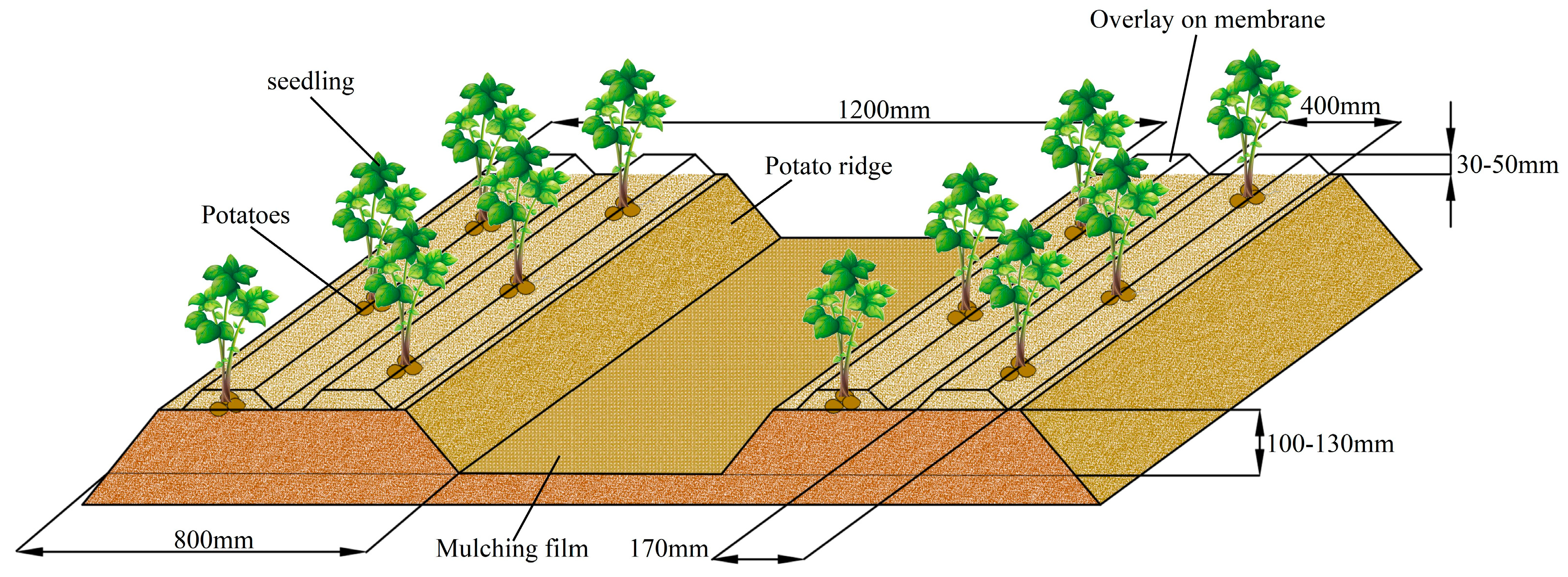
2.1. Agronomic Requirements

Potato sprouts have a unique ability to break the film automatically. After sowing, the film is covered with a layer of soil of 30–50 mm, and the interaction between this layer of soil and the young shoots, combined with the characteristics of potato germination buds avoiding light and cotyledons being tightly closed, means that seedlings can naturally break through the film and come out smoothly. It is based on this characteristic that we have integrated it into the high-yield cultivation technology of potato mulch. Figure 2 demonstrates the design of the ridge shape of potato full-film cover seed row mulch planting, and the model adopts the configuration of large and small ridges, with a total width of 1200 mm, a large ridge width of 80 cm, a small ridge width of 40 cm, and a height of 10–130 mm. Full coverage was carried out using mulch with a width of 1350 mm, and the large ridge was used for planting potatoes. The sowing depth was 130 m, and a layer of soil with a width of 170 mm and a thickness of 30–50 mm was placed above the seed rows. This configuration not only optimizes the soil structure but also significantly increases potato yields.

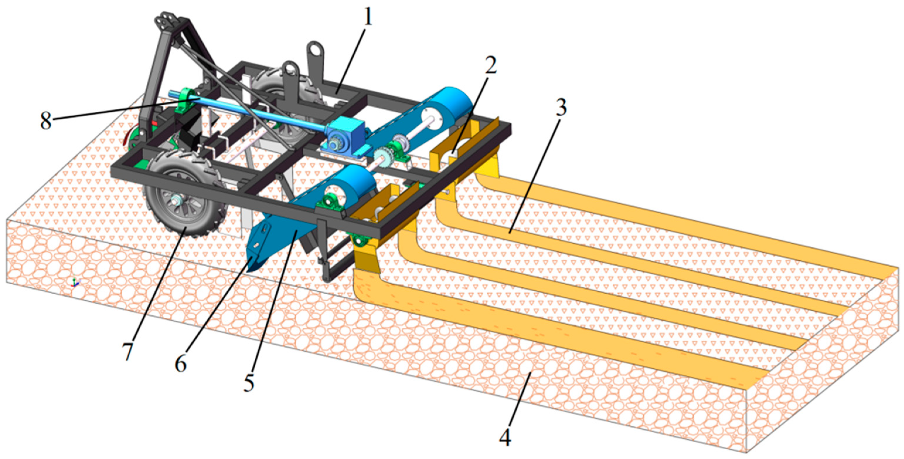
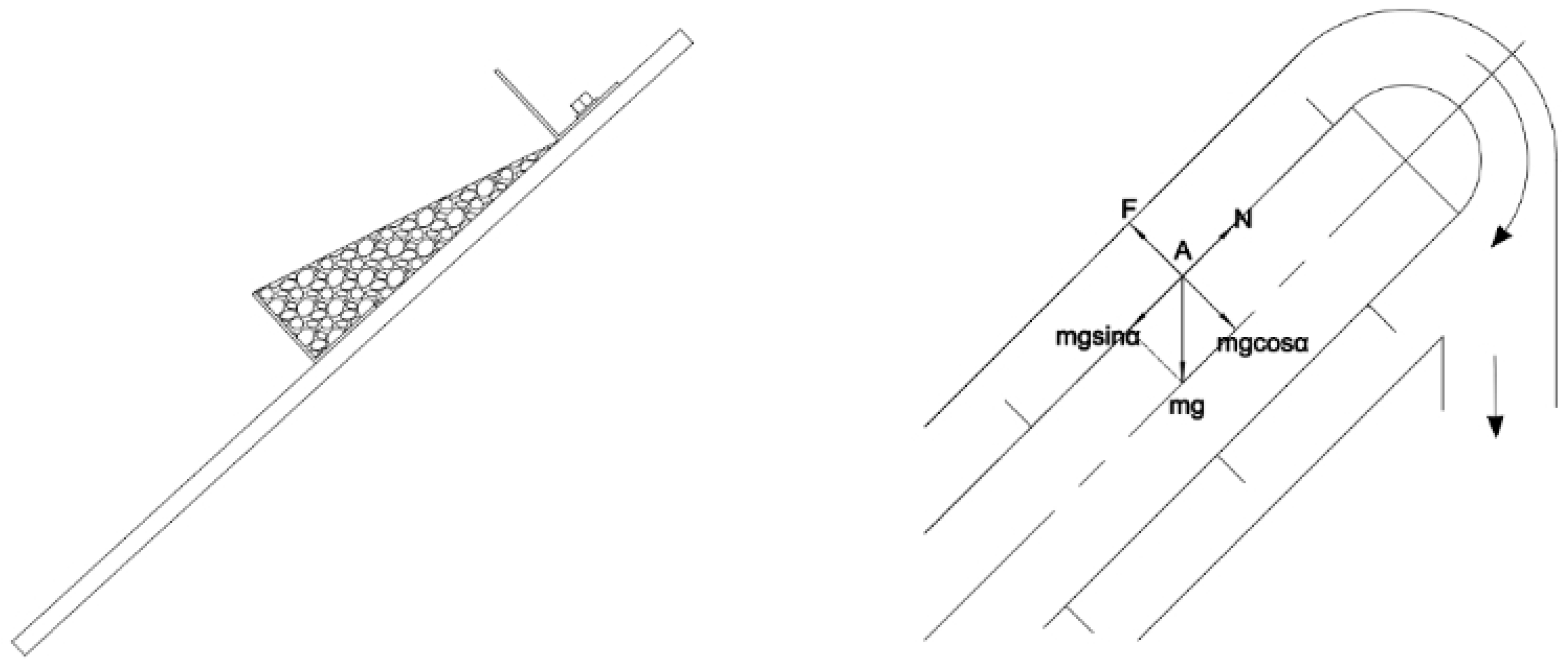
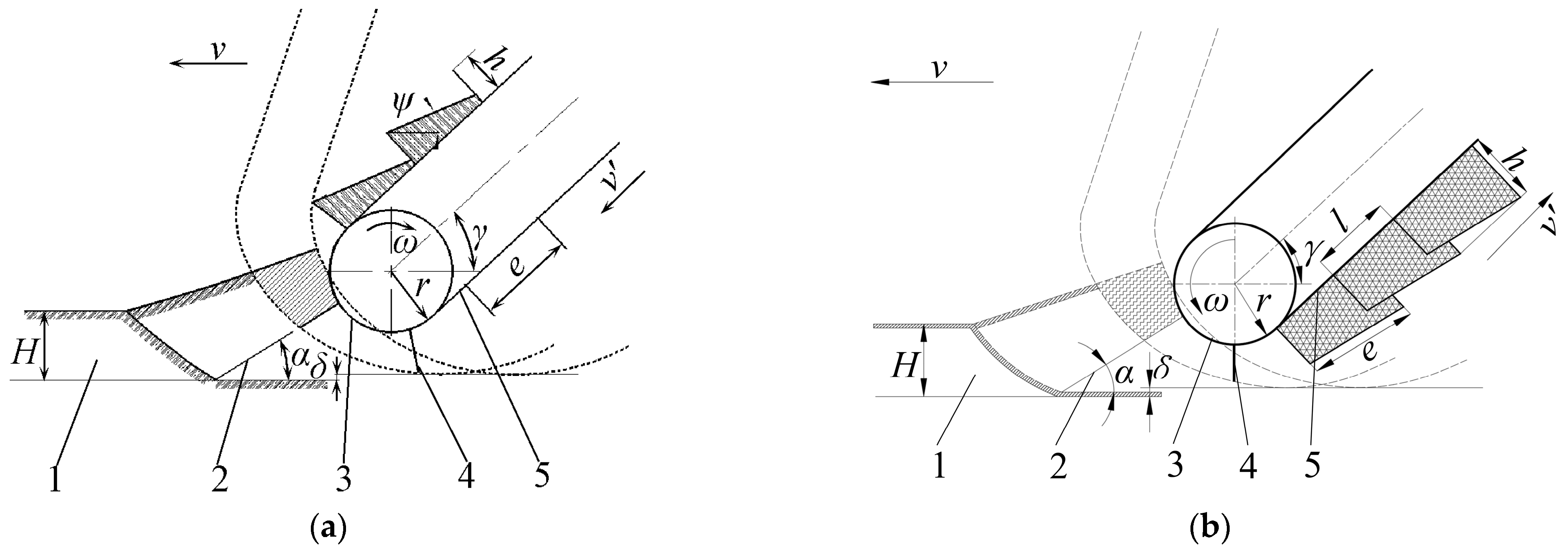
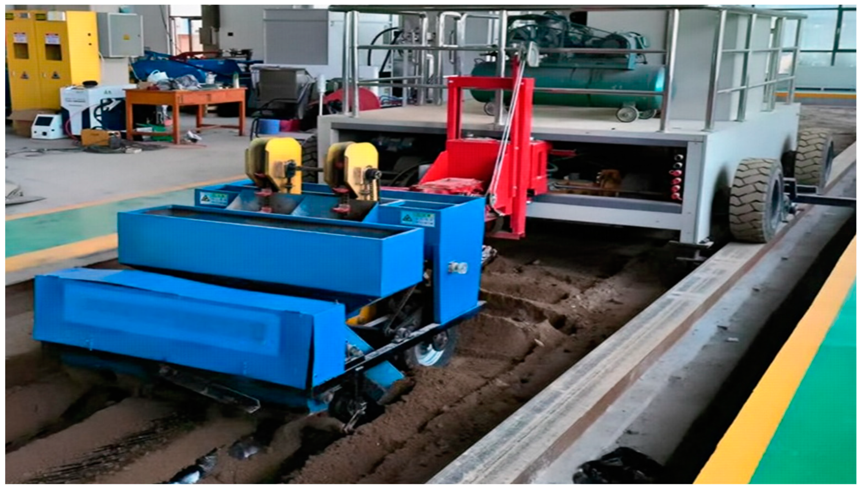
2.2. Principle of Operation

A cross type film mulching device is a mechanical device used for film mulching and planting in farmland, and its structure is shown in Figure 3. It includes components such as the soil pick-up shovel, the lifting chain tensioning mechanism, the follower wheel, the scraping plate, the lifting chain, the soil pick-up shovel depth adjuster, and the main wheel. The implement moves forward by tractor traction, the soil picking shovel (6) shovels up the soil, the soil is transported upward by the chain scraper (5), the screw conveyor transports (2) the soil to both sides, and the soil is evenly covered on the planting holes on the mulch according to the agronomic requirements to complete the mulching operation. The design of this device is based on the team’s existing scraper lifting belt type film mulching device, and after improvement and optimization, it improves the operational efficiency and mulching quality, and the holes are compacted by the mulching soil layer, which promotes the smooth emergence of seed potatoes, eliminates the need for manual mulching and other operational procedures at a later stage, and improves the production efficiency.

2.3. Issues to Be Addressed

The structure of the cross-film mulching device is shown in Figure 4. During mechanical operation, obstruction occurs between the soil picking shovel and the transport chain, which requires stopping the car or additional manpower to carry out the loosening and clearing work, thus causing interruption of the operation process and increasing the consumption of labor. When the scraper lifts the soil upwards, the chain and sprocket of the lifting chain are prone to soil accumulation, which leads to reduced lubrication of the sprocket–chain, and sometimes even the problem of skipping teeth. These two problems not only increase fuel consumption but also affect the operating speed and working efficiency, reduce the quality of operation, and may lead to the amount of mulching being unable to meet the agricultural demand. Therefore, in order to fundamentally solve the reliability problem of the mulching device, it is necessary to optimize the design of the structure of the soil extraction shovel and scraper lifting device.

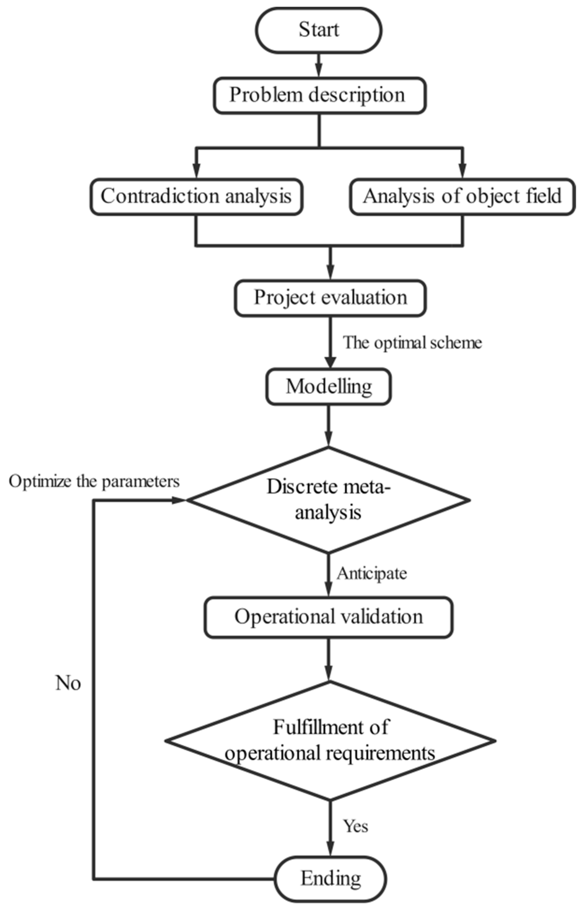
2.4. Application of TRIZ in Design

TRIZ, which stands for “Theoria Resheneyva Isobretatelskehuh Zadach”, originated from Russian, and its English translation is “Theory and Innovative Problem Solving”. As a well-structured and powerful set of innovative problem solving methods, TRIZ provides a systematic, reliable, and repeatable process for solving problems. TRIZ thinking tools have successfully replaced traditional unsystematic trial-and-error and brainstorming methods in many areas of engineering and business.
In the field of engineering, TRIZ provides a structured approach to guiding a designer or engineer towards systematic innovation. By applying tools such as the causal chain (CEC), TRIZ’s law of idealism helps designers identify and solve fundamental problems more effectively. Meanwhile, the application of the concept of contradiction enables designers to focus on their core ideas and utilize the contradiction matrix to obtain a series of practical and creative principles. In addition, the contradiction matrix, one of the core tools of TRIZ, is specifically designed to resolve conflicts between two different parameters. The matrix is based on 39 general engineering parameters and provides innovative perspectives for technical solutions through 40 inventive principles that resolve the corresponding contradictions. After screening and weighing, the optimal solution is selected according to the actual situation [10,11,12].

2.5. Innovative Design of Soil Extraction Shovel Based on “Contradiction Analysis”

The main function of the soil extraction shovel is to dig up the soil and send it to the scraper and then form a rainwater collection ditch on the surface after the soil is lifted. According to the agronomic requirements, two soil shovels are spaced 400 mm, and shovel surface width b and soil scraper are consistent at 150 mm. In order to reduce the resistance of the scraper lifting belt in the process and to prevent the soil scraper scraping the bottom of the ditch soil, when the scraper runs to the driven wheel directly in a vertical state, the soil shovel front should be lower than the apex of the scraper, with the two perpendicular distances δ being 20 mm, the general soil angle θ being 17°–35°, with a length of 80 mm. In the time interval of two scrapers successively taking soil, the soil quantity q is:
q 0 = v Δ t b 0 H
where
  • q0 is the amount of soil extraction;
  • v is the forward speed of the unit;
  • Δ t is the working time of the unit;
  • b0 is the width of the shovel surface of the soil extraction shovel;
  • H is the depth of soil extraction.
The force situation of the shovel is shown in Figure 5, and the general design angle of the shovel is 17°~35°. The following equation can be established from the force diagram of the shovel:
P cos θ T G sin θ = 0 R G cos θ P sin θ = 0
where
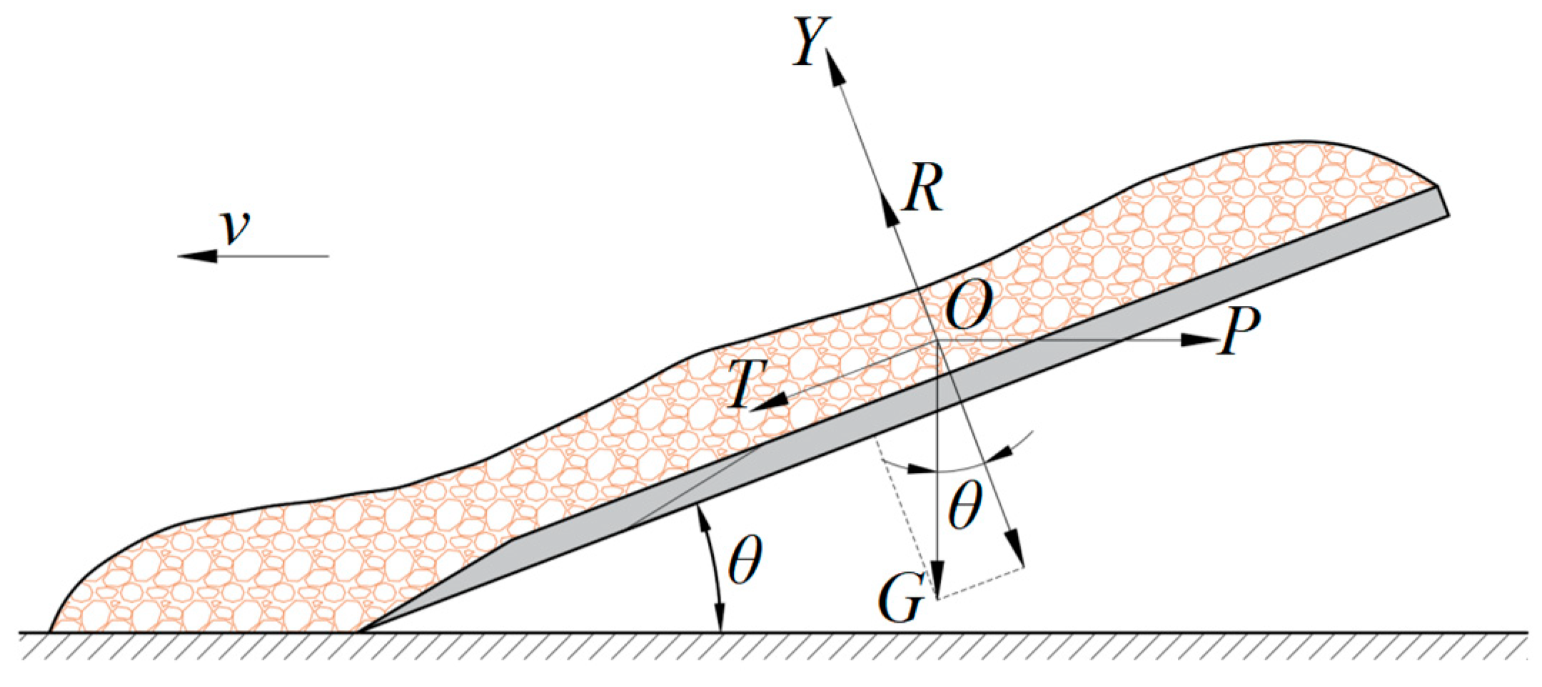
  • P is the force required to move the earth extraction shovel to dig up the soil;
  • R is the reaction force of the earth extraction shovel on the soil;
  • θ is the inclination angle of the shovel;
  • μ is the coefficient of friction of the soil on the earth extraction shovel.
  • G is the acceleration of gravity.
  • T is the friction of the shovel on the soil.
From this it can be deduced that the inclination angle of the earth extraction shovel is:
θ = arctan P μ G μ P + G
The angle of inclination of the earth moving shovel directly affects the force it is subjected to. The smaller the angle of inclination, the less soil is lifted and the less resistance is generated. Therefore, the tilt angle of the shovel should be as small as possible in order to ensure the soil extraction performance.
The soil undergoes changes in state such as plastic flow and disintegration as the earth removal shovel works. As the machine advances, the mixture of soil and weeds is prone to form a blockage above the earth extraction shovel. As can be seen from Equation (1), reducing the width of the shovel surface b and the digging depth H reduces the amount of soil lifting q, which reduces the resistance and ensures that the soil flows smoothly over the soil extraction shovel to avoid accumulation. However, if the area of action of the soil extraction shovel is reduced, the amount of soil cover will be reduced again. By describing the key problem of the earth extraction shovel, the problem is transformed into a technical contradiction of TRIZ (i.e., when improving one parameter or characteristic of a technical system, it will cause the deterioration of another parameter or characteristic of the system at the same time), and the basic model for solving the problem of the technical contradiction is shown in Figure 6.
Thus, the above paradoxical conflict can be summarized as follows: while improving the force, the quantity of the substance or thing deteriorates. By finding the contradiction matrix, we can obtain the specific solution applicable to the sub-matrix of this problem. The specific solutions are shown in Table 1.
The following innovation principle tips can be obtained.
Innovation Principle 14—Surfacing Principle, which advocates the use of shapes such as curves, spheres, and spheroids to replace traditional straight lines and flat surfaces in design. Examples include the use of forms such as rollers, spheres, or spirals or the use of centrifugal force to achieve non-linear motion by rotating an object. This approach offers multiple advantages, including reduced friction, optimized material flow, and enhanced overall system performance.
Innovation Principle 29—Pneumatic and Hydraulic Structural Principle, which advocates the use of air or hydraulic technology to replace traditional system components. By utilizing the properties of gases or liquids, especially expandable or inflatable objects, the application of pneumatic and hydraulic principles can be realized. This approach has a wide range of applications in many fields, such as aerospace, vehicles, and robotics, and can significantly improve the efficiency and performance of systems.
Innovation Principle 18—Mechanical Vibration Principle, which advocates the excitation of mechanical vibration of an object in order to increase the vibration frequency or utilize the resonance frequency. This method can produce a regular, periodic change that realizes some effect or system change within a specific interval. The principle of mechanical vibration is used in many engineering fields, such as vibrating screens and vibrating motors, to improve the stability and efficiency of a system.
Innovation Principle 36—Phase Change Principle, which utilizes the effect or system change produced by a substance in the process of phase change. Through the rational use of phase change, energy conversion and control can be achieved to optimize the performance of the system. The phase change principle has a wide range of applications in energy conversion, materials science, aerospace, and other fields. For example, the use of phase change materials to absorb and release heat to achieve temperature control, or the use of volume changes in the phase change process to create new structures or functions.
Referring to the description of the innovation principles, the innovation principles in Table 2 were analyzed and screened to find specific solutions based on specific problems.
Innovation Principle 14 (Surfacing Principle) is used to suggest that the shovel surface of the earth extraction shovel is designed as a curved surface, i.e., a bionic shovel. According to the bionic test, it is shown that the curved surface has both better drag reduction performance and can have the effect of breaking up the soil with less soil disturbance. Prompted by Innovation Principle 29 (Pneumatic and Hydraulic Structure Principle), with air as the medium, a blower is proposed to be used to blow the soil into the scraper lifting chain, so as to solve the problem of soil congestion. Prompted by Innovation Principle 18 (Mechanical Vibration Principle), by the crank linkage mechanism to drive the soil extraction shovel for reciprocating motion to realize the vibration, the use of vibration technology of the shovel working resistance is low, power consumption is low, the viscosity reduction effect is obvious, and the effect of soil crushing is good. However, it is necessary to add an additional driving device to the earth moving shovel, which will increase the complexity of the mechanism. Or, according to the tips, by the vibration motor as a soil shovel excitation source and power source, the soil shovel makes an up and down reciprocating motion, so that the soil shovel above the soil is relatively loose and has good mobility with smooth transportation.
In summary, through the program analysis and combined with practical applications, the structure and object of the soil extraction shovel designed in Program 1 are screened out, and the innovative design of the soil extraction shovel is as follows: improve the traditional flat shovel into a curved shovel and shorten the length of the shovel, and then carry out carburizing and quenching of the shovel in order to improve the hardness and abrasion resistance of the shovel (spraying resistance reducing materials). The design of the shovel is expected to fulfill the following functions during joint planting operations: at a certain angle of entry, the shovel blade effectively cuts the soil and drives the soil upward along the shovel face. The advantage of the curved surface design is that it can produce the effect of crushing the soil during the movement of the soil along the shovel surface. This design not only improves the smoothness of operation of the entire machine but also helps to reduce the resistance between the soil and the shovel surface, thus improving the economy of operation.

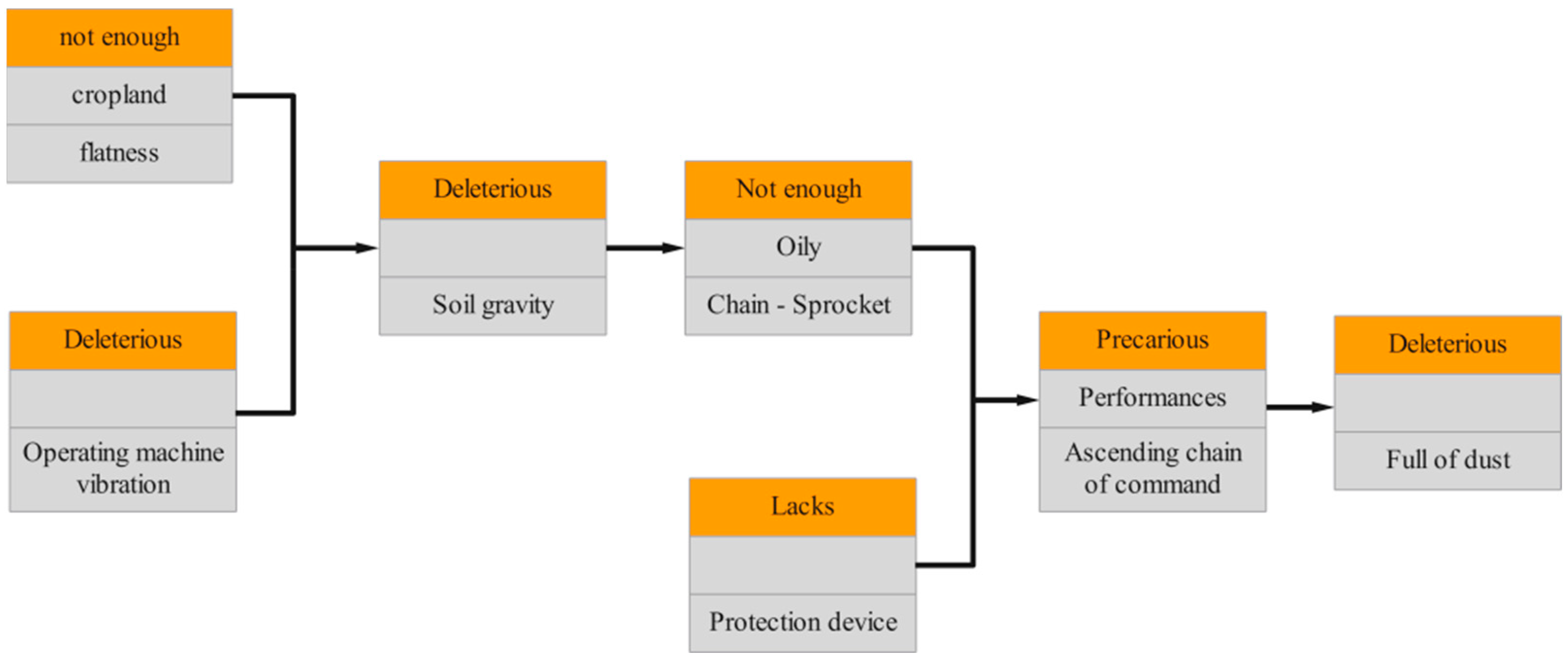
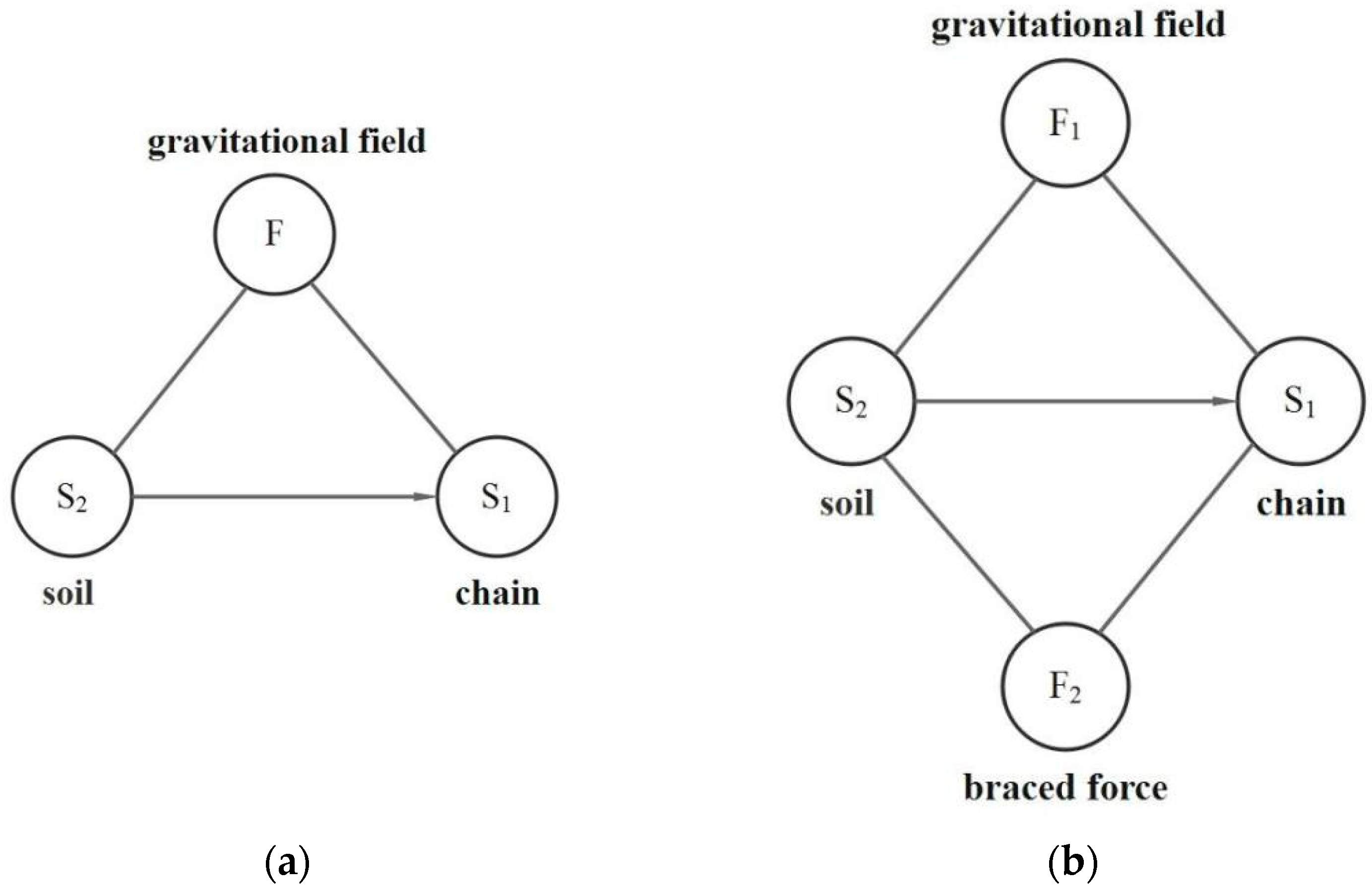
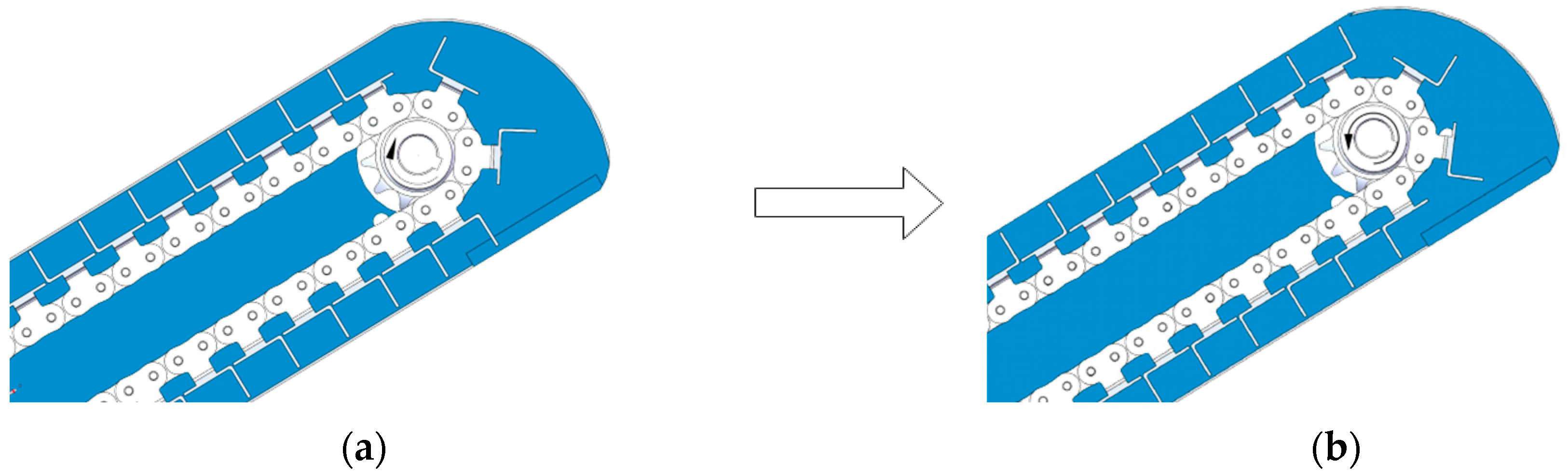
2.6. Innovative Design of Scraper Lifting Device Based on “Object Field Analysis”

The scraper lifting device serves as the core component for the task of efficiently lifting and transferring soil [13]. During operation, the device gathers the soil with the soil lifting shovel and subsequently transports it to the soil distributor, driven by the lifting chain. After precise distribution by the soil distributor, the soil is evenly spread on the corresponding film strip, thus ensuring the efficient implementation of the film mulching operation, as shown in Figure 7.
Occasionally, in complex operating environments, soil can build up inside chains and sprockets. This situation leads to a decrease in the lubrication effect of the sprocket–chain, and the normal rotation of the lifter is impeded, further affecting the overall soil covering effect. In order to accurately analyze the cause of the degraded lubrication performance, an in-depth study was conducted using the cause-and-effect analysis method, as shown in Figure 8.
In the causal analysis of the scraper lifting device, the main causes were the lack of appropriate protection devices and the insufficient effectiveness of the lubrication system, which led to frequent damage to the chain–sprocket assembly. In order to describe and solve the problem more precisely, the causal analysis model was transformed using the object field model. Based on the steps applied to the standard solution, it was determined that this was a system problem that needed improvement. Specifically, the problem occurs when the soil accumulated on the chain clogs the sprocket, thus affecting the efficiency of the entire unit.
Obviously, the object field model of the problem according to the causal analysis in Figure 8 is of the type that produces a harmful effect, and the standard solution 1.2.4—counteracting the harmful effect with the field F2—is applied. Therefore balancing the soil gravity (harmful) requires the introduction of a force in the opposite direction to the soil gravity, thus eliminating its detrimental effect, so the object field model of the solution is shown in Figure 9b, i.e., the supporting force FN. Combined with the specifics of this system and evaluating the solution according to the dimensions of technical difficulty, reliability, desirability, and economy, the final solution is presented—change from the original clockwise rotation of the main wheel (Figure 10a) to counterclockwise rotation, i.e., change the conveyor from the original upper scraping type to the lower scraping type, as shown in Figure 10b.
The movement of the lowest point of the scraper across the membrane mulching device is the synthesis of two kinds of movement, namely, the lowest point of the scraper around the center of the driven wheel of the uniform speed rotary movement and the forward movement of the unit operation, shown in Figure 11, to establish the lowest point of the scraper displacement equation (see Equation (4)), which indicates that when the machine’s other parameters are fixed, the smaller the ratio of the linear velocity of the transport chain to the forward speed of the unit, the longer the time to take the soil and the time of the maximum soil taking capacity limitations. Within the scope of the maximum soil extraction capacity, the greater the soil extraction capacity of the mulching device; the line speed of the scraper type soil transfer device conveying material is generally 1–2 m/s, the line speed of the lifting chain of the mulching device was selected to be 1.5 m/s, and the forward operating speed of the potato film planter was 0.8 m/s.
x = r ϕ v v + ( r + h ) sin ϕ y = ( r + h ) ( 1 cos ϕ )
where
  • x is the horizontal displacement of the scraper end;
  • y is the vertical displacement of the scraper end;
  • r is the radius of the driven wheel;
  • h is the height of the scraper;
  • v is the speed of the ascending chain;
  • v is the forward speed of the unit;
  • ϕ is the turning angle of the scraper.
Figure 11a,b are the working principles of the upper scraper and lower scraper lift mechanism, respectively, and the angle between the scraper and the horizontal plane reflects the angle of internal friction of the soil. The volume of soil transported is controlled by the length l of the lifting chain, and the volume is determined by multiplying the area of the scraper end with the width. When the advancing length of the machine is l′, the soil lifting amount Q of the upper scraper lifting mechanism is
Q = η i b l 2 tan ( γ ψ ) l l h / tan ( γ ψ ) η b l i [ h l tan ( γ ψ ) 2 ] l < h / tan ( γ ψ )    
The length of the machine forward movement is l′. The soil lifting quantity Q of the lower scraper lifting mechanism is (γ = ψ):
Q = η b l i [ h l tan ( γ ψ ) 2 ]
where η is the conveying efficiency in Equations (5) and (6), mainly related to the fullness coefficient; γ is the angle between the lifting chain and the horizontal plane; h is the height of the scraper; b is the width of the scraper; i is the ratio of the speed of the lifting chain to the forward speed [14].

3. Simulation Test

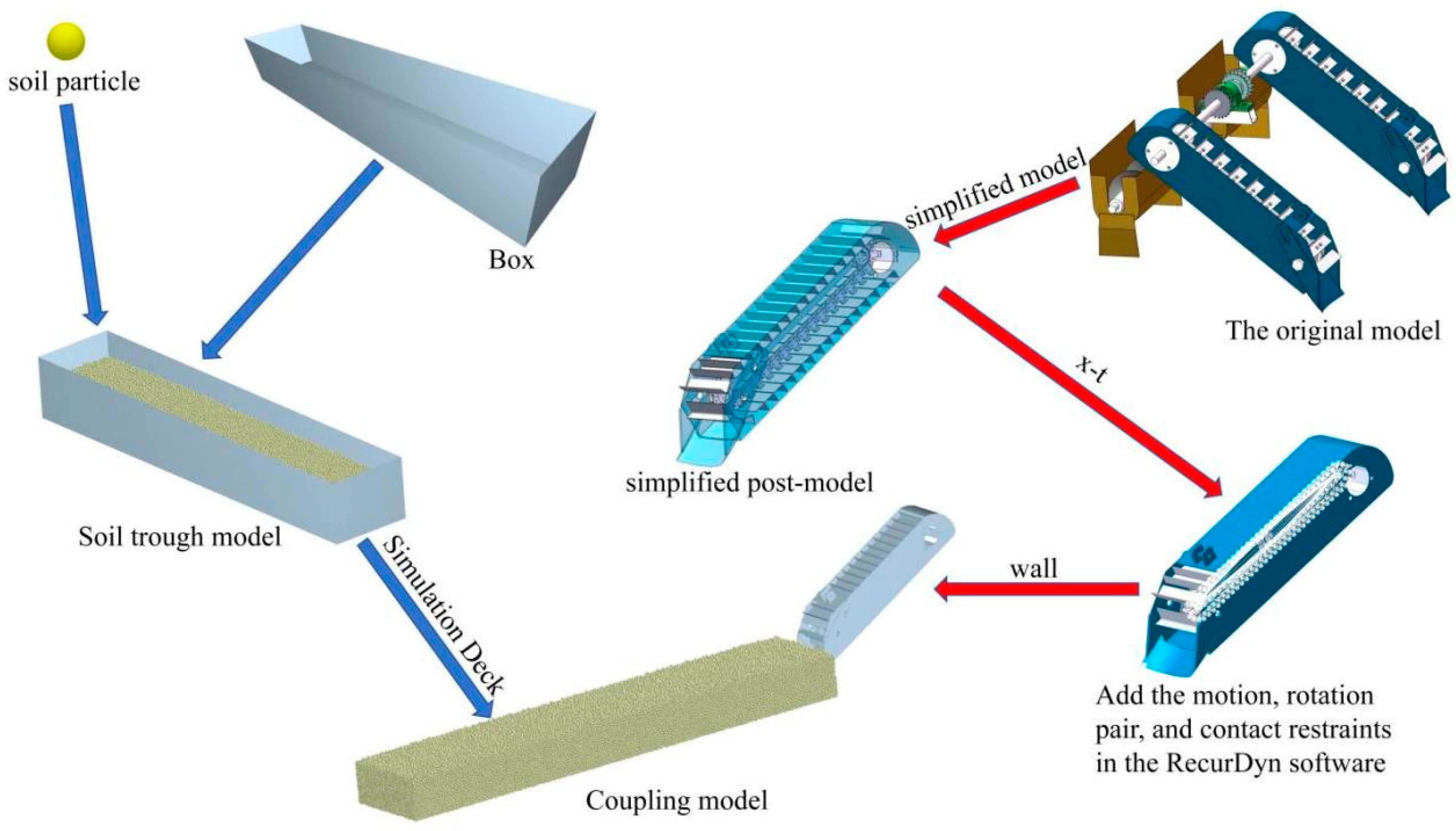
3.1. Discrete Element Modeling

In order to verify the feasibility of the design, the discrete distinct element method (DEM) was introduced to simulate the optimized design. EDEM was used to establish a soil model to simulate the mulching process, and the design with good mulching effect was selected for the experiment by counting the number of actual mulching particles and the resistance of the soil lifting shovel before and after optimization.
The default Hertz–Mindlin non-sliding contact model of EDEM software 2022.3 was used to simulate the soil used in the mulching device. Since most of the soil used in the mulching mechanism is surface soil, in order to highlight the experimental effect and improve the efficiency of the simulation and calculation, no bonding was set between the particles in the mulching process. When establishing the soil model with the help of discrete unit method software, due to the complexity of the soil structure, it is necessary to characterize its properties with several soil contact model parameters, such as the radius of soil particles, density, Poisson’s ratio, shear modulus, elasticity recovery coefficient, and coefficient of static and dynamic friction. The parameters obtained with reference to relevant literature [15] are shown in Table 3 below. To establish the soil model, a rectangular soil tank with a length of 2100 mm, width of 400 mm, and height of 300 mm is firstly established, and the soil tank is filled with 230,000 round particles placed inside the soil tank, which is exported as Figure 12 after the generation is completed.
In order to simulate the actual operation of the device in the plot, a virtual soil tank is created and it is imported into the EDEM software for simulation together with the optimized device. In order to improve the efficiency of the simulation calculation, the device model is simplified, which will not affect the operation effect. In this study, the subject material property of the simulation model is set to 65Mn steel, because of the soil abrasion caused by the soil shovel is larger, and the specific parameters are shown in Table 3. Also, taking into account the efficiency of the simulation calculations, the soil particles are with a diameter of 5 mm and the material properties of the soil particles are as follows: Poisson’s ratio is 0.31, the density is 2600 kg/m3, the shear modulus is 1.0 × 10⁷ Pa, and the contact model between soil particles is Hertz-Xtra, which is the same as that in the simulation. The Hertz–Mindlin with bonding model was used to simulate the bonding between soil particles. To ensure that the simulation is carried out accurately, it is also necessary to set the contact parameters between soil and soil and between steel and soil particles, referring to the literature [16,17,18]. The bonding parameters for the simulated model contact are shown in Table 4.

3.2. Multi-Body Dynamics Modeling

In accordance with the above innovative design scheme, SolidWorks software 2023 was used for 3D modeling to obtain the 3D model of the earth extraction shovel and scraper lifting device as shown in Figure 13.
After saving the three-dimensional model of the soil lifting device as x_t, it is imported into RecurDyn software, and in accordance with the actual motion characteristics of the chain drive, a rotating vice is added between every two adjacent inner and outer links, and the contact constraints are added between every inner link and the active sprocket and follower sprocket [19,20,21], as shown in Figure 14.
After establishing the multi-body dynamics model, according to the theoretical analysis and pre-test, the simulation contact parameters were adjusted to determine the forward speed of the unit to be 400 mm/s, the linear speed of the soil lifting device to be 1.5 m/s, and the angle of the soil removing shovel to be 30°.

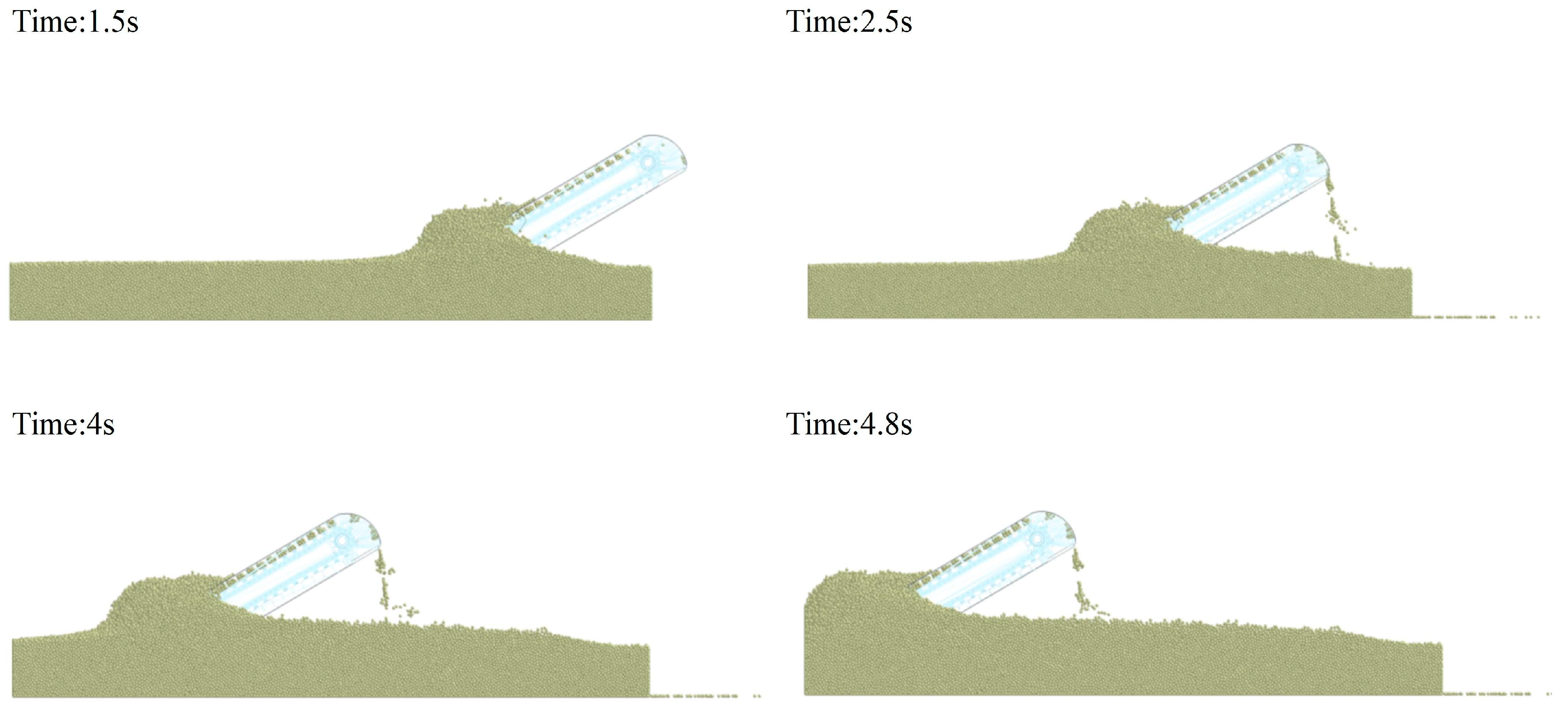
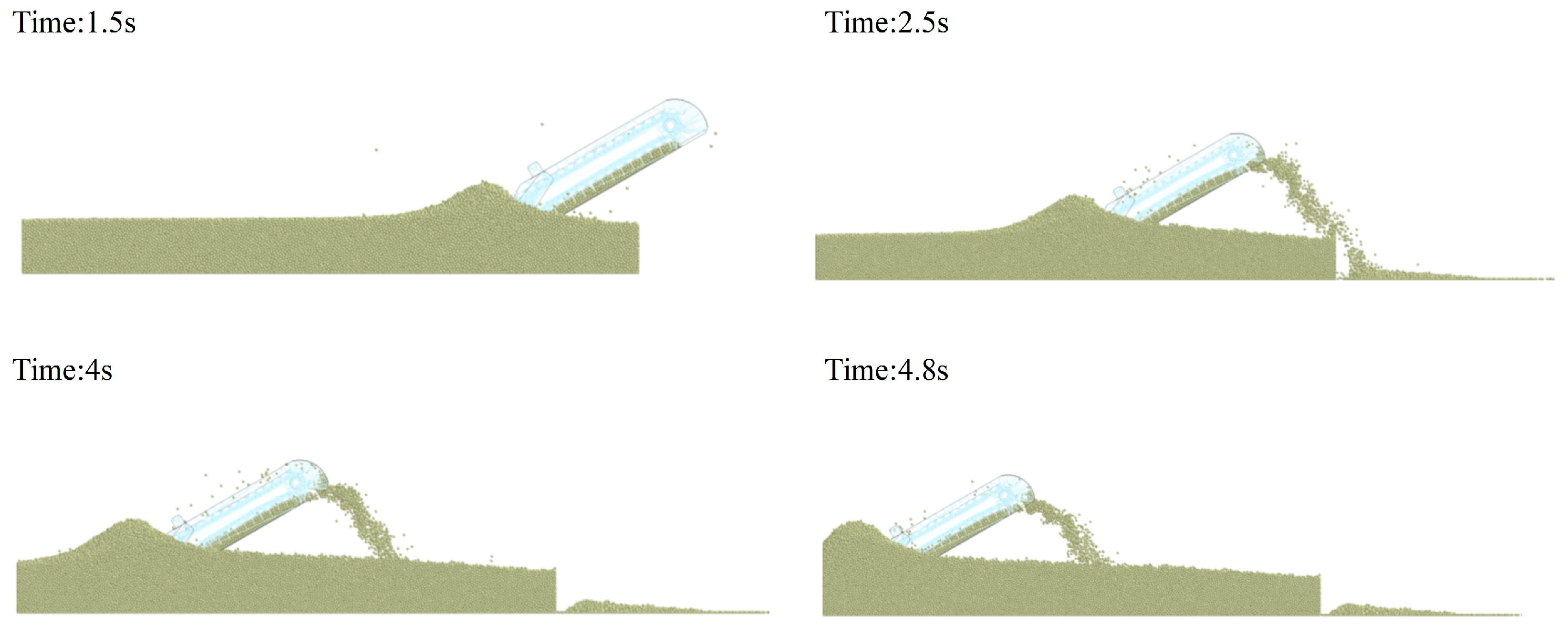
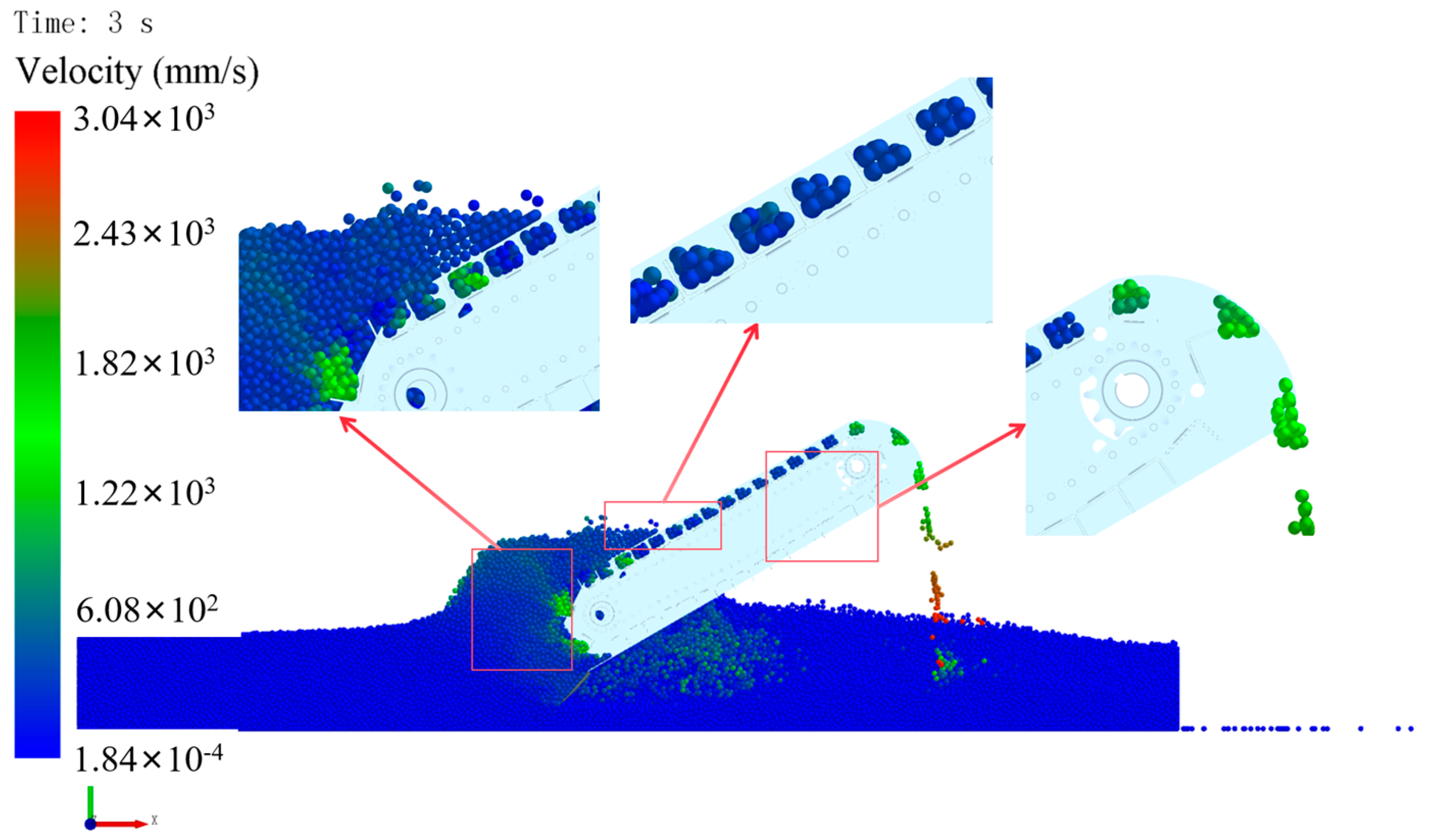
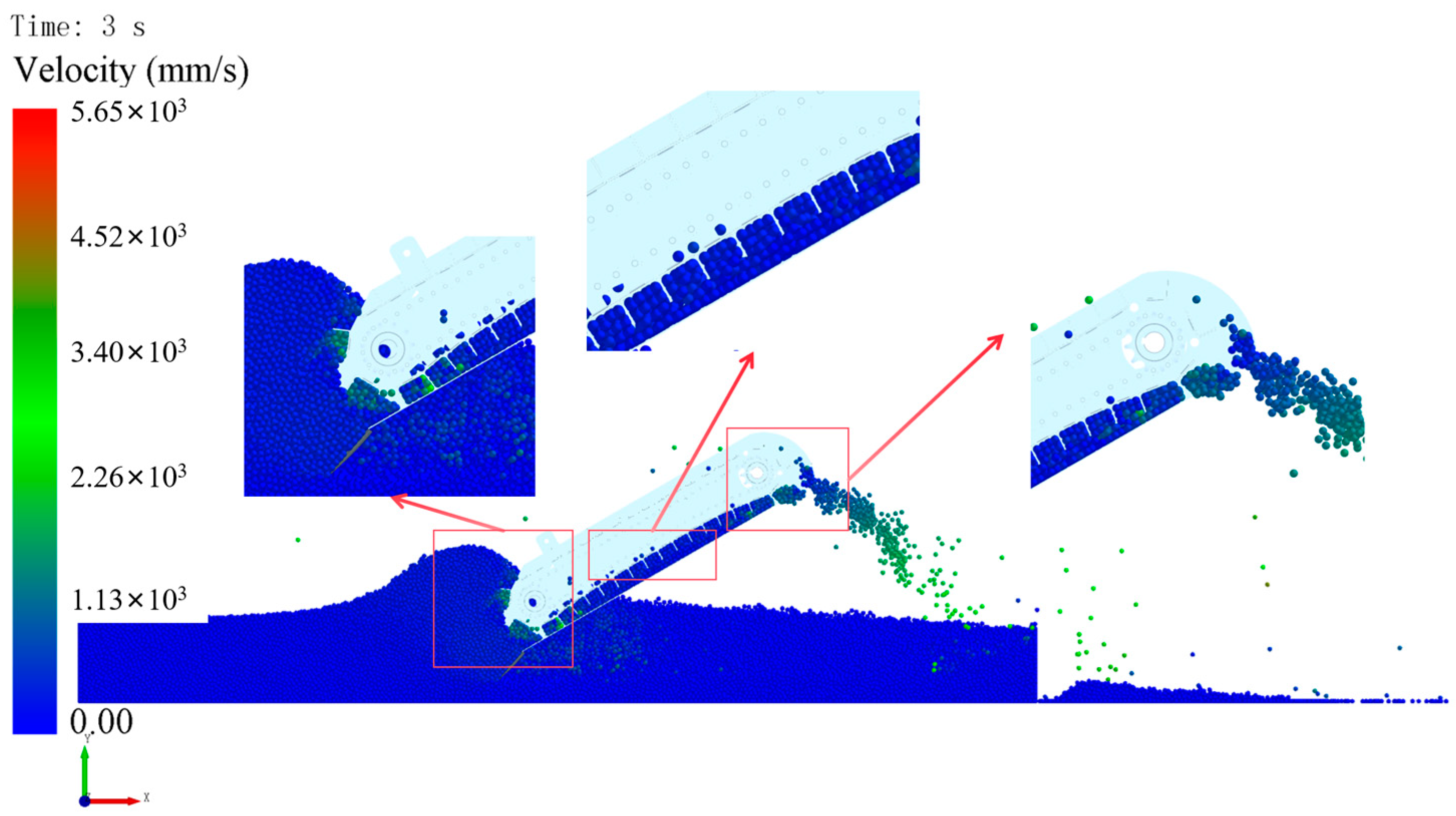
3.3. Simulation Tests and Results

The multi-body dynamics model generates a wall file which is exported and saved, then the established discrete element model is opened and exported to a Simulation Deck file in the Analyst module, the simulation time is set to start from 0 s, then the exported Simulation Deck file is opened, and the exported wall file is imported into the discrete element model. Adjusting the relative positions of the simulation model [22,23], the modeling process is shown in Figure 15.
The simulation results of the upper scraping soil lifting device are shown in Figure 16. From the simulation results of the upper scraping soil lifting device, it can be seen that at the beginning of the simulation, after 1.5 s, the ascending chain scraper will lift the soil particles from the top to the soil outlet with smooth operation, the number of soil particles of the conveyor is small, the flow rate of the outlet is unstable, and the congestion curve formed with the soil particles in the advance is high. It is easy to cause soil accumulation and blockage at the soil inlet of the soil lifting device.
The simulation results of the lower scraping soil lifting device are shown in Figure 17. From the simulation results of the lower scraping soil lifting device, it can be seen that after 1.2 s, at the beginning of the simulation, the scraper lifts the soil particles from the bottom to the soil outlet. Throughout the simulation process, the lower scraping soil lifting device conveys a large amount of soil particles during the whole working process, and the flow rate of the soil outlet is stable.
Comparing the simulation results of the upper and lower soil lifting devices at different times, the soil particle conveying volume and conveying efficiency of the lower scraping soil lifting device are significantly higher than that of the upper scraping soil lifting device, and the particle flow of the lower scraping outlet is also more stable. This shows that the lower scraping soil lifting device is more in line with the agronomic requirements of potato mulching operation.

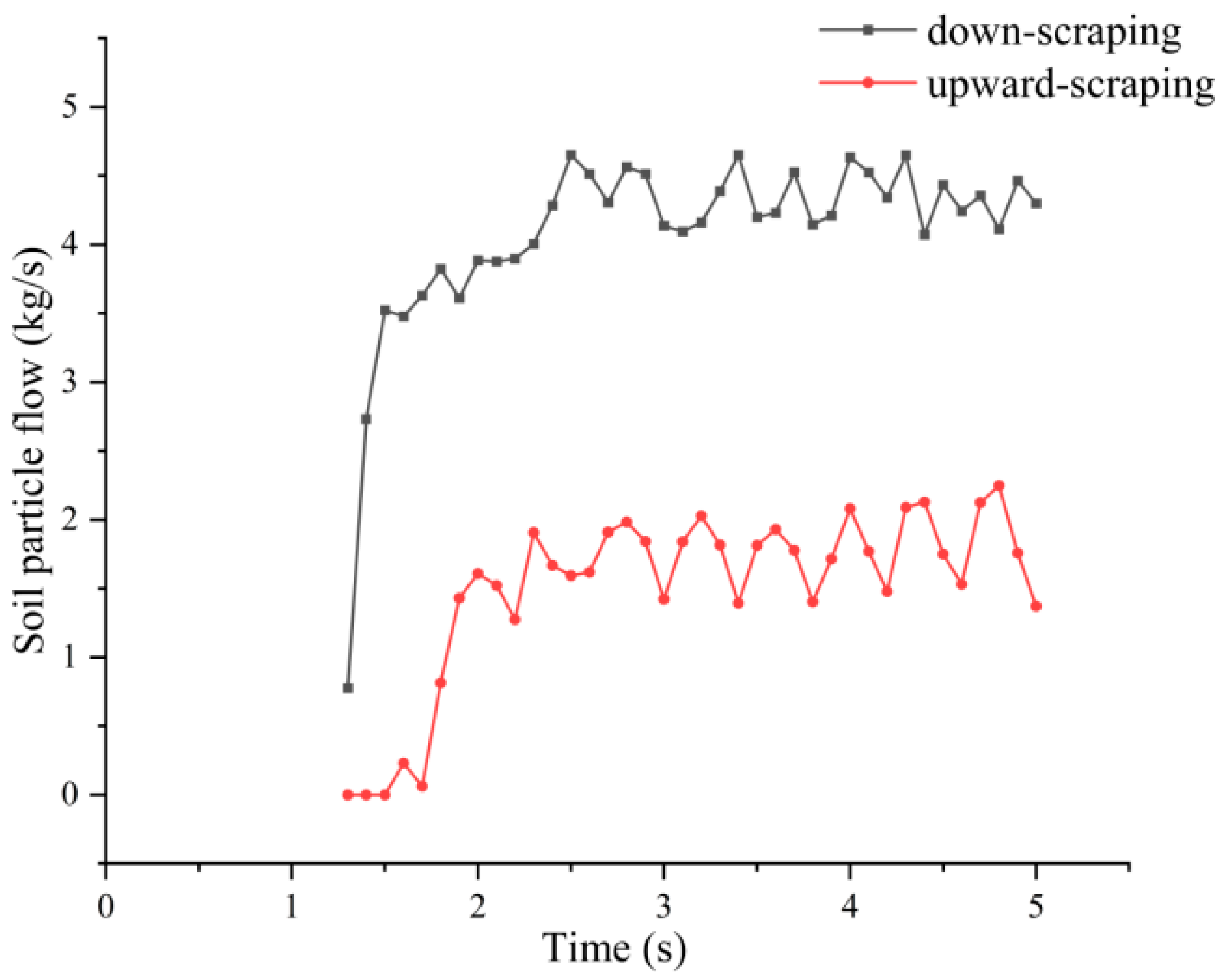
3.4. Analysis of Simulation Test Results

In order to further analyze the working process of the two soil lifting devices and investigate the root cause of the above phenomenon, the simulation model was dissected along the middle plane and the soil particle velocity cloud of the soil lifting device was obtained in the EDEM post-processing module.
The soil particle velocity cloud diagram of the upper scraping soil lifting device is shown in Figure 18. The working process of the whole soil lifting device is analyzed through the local zoomed-in diagram. When the soil lifting device starts to work, the active sprocket of the upper scraping soil lifting device runs clockwise, the ascending chain scraper plate starts to move under the action of the active sprocket and chain, and the space for conveying soil is formed between two adjacent scraper plates. As the machine moves forward, the soil particles are shoveled up by the soil lifting shovel, and under the joint action of the soil lifting shovel and the soil particles in front, the soil particles are transported upward from the bottom under the action of the scraper, then they enter the space formed between the two neighboring scraper plates and are transported upward by the ascending chain scraper. When transported to the top, the soil scraping plate makes a circular movement around the sprocket wheel, and the soil particles transported by the soil scraping plate are thrown to the soil lifting shell under the action of centrifugal force and finally leave the soil lifting device by the soil outlet below the soil lifting shell under the guidance of the soil lifting shell.
The soil particle velocity cloud diagram of the lower scraping soil lifting device is shown in Figure 19. The working process of the whole lower scraping soil lifting device is analyzed through the local zoomed-in diagram. When the soil lifting device starts to work, the active sprocket of the lower scraping soil lifting device runs counterclockwise. With the forward movement of the machine, soil particles are shoveled up by the soil shovel, and under the joint action of the soil shovel and the soil particles in front, the soil particles are transported by the scraping plate from the top to the bottom and then enter into the space formed between two neighboring scraping plates and are transported upward by the ascending chain scraping plate. When conveyed to the top of the soil lifting device, the soil particles leave the soil lifting device along the soil outlet below the soil lifting shell.
Taking two kinds of speed direction cloud diagrams of the soil lifting device’s soil picking shovel portion and the upper scraping soil particle movement direction cloud diagram shown in Figure 20, it can be seen in the upper scraping soil lifting device, after the soil picking shovel shovels up the soil particles and due to the sprocket rotating clockwise, when the soil particles come into contact with the scraping boards, that some of the soil particles will be driven by the scraping boards from the downward and upward movements. Due to inertia, the soil driven by the scraping plate does not all enter the space formed between two adjacent scraping plates, so the number of soil particles lifted by the lifting chain is limited, resulting in a decrease in the lifting efficiency of the upper scraping soil lifting device.
The lower scraping soil particle movement direction cloud diagram is shown in Figure 21. The lower scraping soil lifting device in the soil picking shovel shovels up the soil particles and, due to the sprocket counterclockwise rotation, when the soil particles and the scraping plate contact, the soil particles will be in the scraping board under the drive from the top due to the downward movement and due to the direction of the movement of soil particles with the soil lifting shell as well as the soil picking shovel support, resulting in a majority of soil particles in the scraping plate entering the two adjacent scraping boards. The soil particles are supported by the soil lifting shell and the soil lifting shovel in the direction of the soil particles. Therefore, the working efficiency of the lower scraper is higher than that of the upper scraper.
To further analyze the conveying efficiency of the two soil lifting devices, a flow sensor was added at the soil outlet of the soil lifting hood to measure the flow of soil particles at the soil outlet of the two soil lifting devices at different times as shown in Figure 22.
The flow rates of the soil outlet of the upper scraping and lower scraping soil lifting devices were measured separately, starting from 0 s with a time interval of 0.1 s, and the flow rate graph is shown in Figure 23.
As shown through the flow–time curve, the upper scraping soil lifting device works stably in 2 s. The flow rate fluctuates around 1.5 kg/s, the conveying volume is small, and the flow rate fluctuates greatly, which will cause the uneven thickness of soil on the membrane mulching area in the actual mulching operation, which is not in line with the agronomic requirements of potato mulching and will affect the growth of potato seedlings in the later stage. The lower scraping soil lifting device starts to work at 1.5 s, and the flow rate is maintained at about 4.5 kg/s. Compared with the upper scraping soil lifting device, the flow rate of the lower scraping soil lifting device is higher and more stable.
In summary, the lower scraping soil lifting device has a large soil conveying capacity, high conveying efficiency, and stable flow rate at the soil outlet, which is more in line with the requirements of potato mulching operation on the membrane.

4. Test Validation

In order to verify the actual operational performance of the improved soil extraction shovel and scraper lifting chain membrane mulching device, a working performance test was conducted in March 2022 on the soil trough of the School of Mechanical and Electrical Engineering of Gansu Agricultural University, and the test apparatus and equipment included a soil trough, soil trough truck, 2 cm−2 potato seedling strip mulching planting machine, soil moisture content tester, tape measure, balance, stopwatch, tachometer, etc. The test site is shown in Figure 24. The length of the soil trough is 10 m, the width is 1.2 m, and the maximum traction force of the soil trough truck is 15,000 N, which can realize stepless speed regulation in the speed range of 0.3–9 km/h. The power of the planting machine is obtained from the soil tanker, and the power is transmitted to the prime mover of the mechanism through the belt drive and chain drive, with a total transmission ratio of 1:30. According to the required speed of planting, the speed of the soil tanker is set at 1 m/s, and the test soil is yellow sheep’s soil, with a soil moisture content of 13.2–15.9%, a soil capacity of 1300 kg/m3, and a soil solidity of less than 0.16 MPa. Under the working conditions, with reference to GB/T 25417-2010 [24] “Technical conditions of potato planting machine”, NY/T 1415-2007 [25] “Technical specification for quality evaluation of potato planting machine”, NY/T 987-2006 [26] “Quality of film spreading and hole seeding machine operation”, and relevant requirements of agricultural machinery test methods, the probability of congestion and the amount of soil cover on the entire film surface are determined.
Potato planting machine congestion refers to the phenomenon of soil aggregation caused by the operational performance of the soil extracting shovel during the operation of the machine, resulting in congestion of the operating device and a reduction in the amount of mulch, which impedes the normal traveling operation of the planting machine. In order to determine the operating performance of the soil extraction device, the operating processes strictly control other variable factors, namely, field performance test, the total number of tests nz (times), the number of times of congestion in the test process nyt (times), and the probability of planting machine congestion n (%) is calculated as follows:
n = n y t n z × 100 %
When the potato planter is working stably in the soil tank, a distance of 1 m in length is randomly selected in the test area, all the soil on the whole membrane surface is collected, and its weight is measured by using an electronic scale and recorded as the amount of soil covering the whole membrane surface. The test was repeated 10 times, and the mean value of soil cover was calculated, then
X = m 1 m 0 × 100 %
where X is the whole membrane surface soil covering quantity qualified rate, %, m1 is the average value of the soil covering quantity of the planter, kg, m0 is the weight calculated according to the standard, kg.
As shown in Table 5, the soil shovel and scraper lifting chain membrane mulching device were improved to a certain extent. This provides a reference for the improvement of the planting machine operating performance for a self-developed potato full-film cover membrane seedling with mulching planting machine and enhancement of joint operation.

5. Conclusions

(1)
Using TRIZ theory to carry out “contradiction analysis” on the soil extraction shovel and putting forward a structural form that can realize the effective coupling of multi-schemes according to the characteristics of the scraper lifting and transporting chain-type film mulching device provides a guarantee for the smoothness, high efficiency, and reliability of the potato planting machine’s operation process. Based on the “object field analysis”, the cause-and-effect analysis of the scraper lifting device, through the invention of the principle of the final solution, improves the smoothness and economy of the whole machine and solves the problem of poor lubrication of the sprocket–chain in the lifting system in the process of operation.
(2)
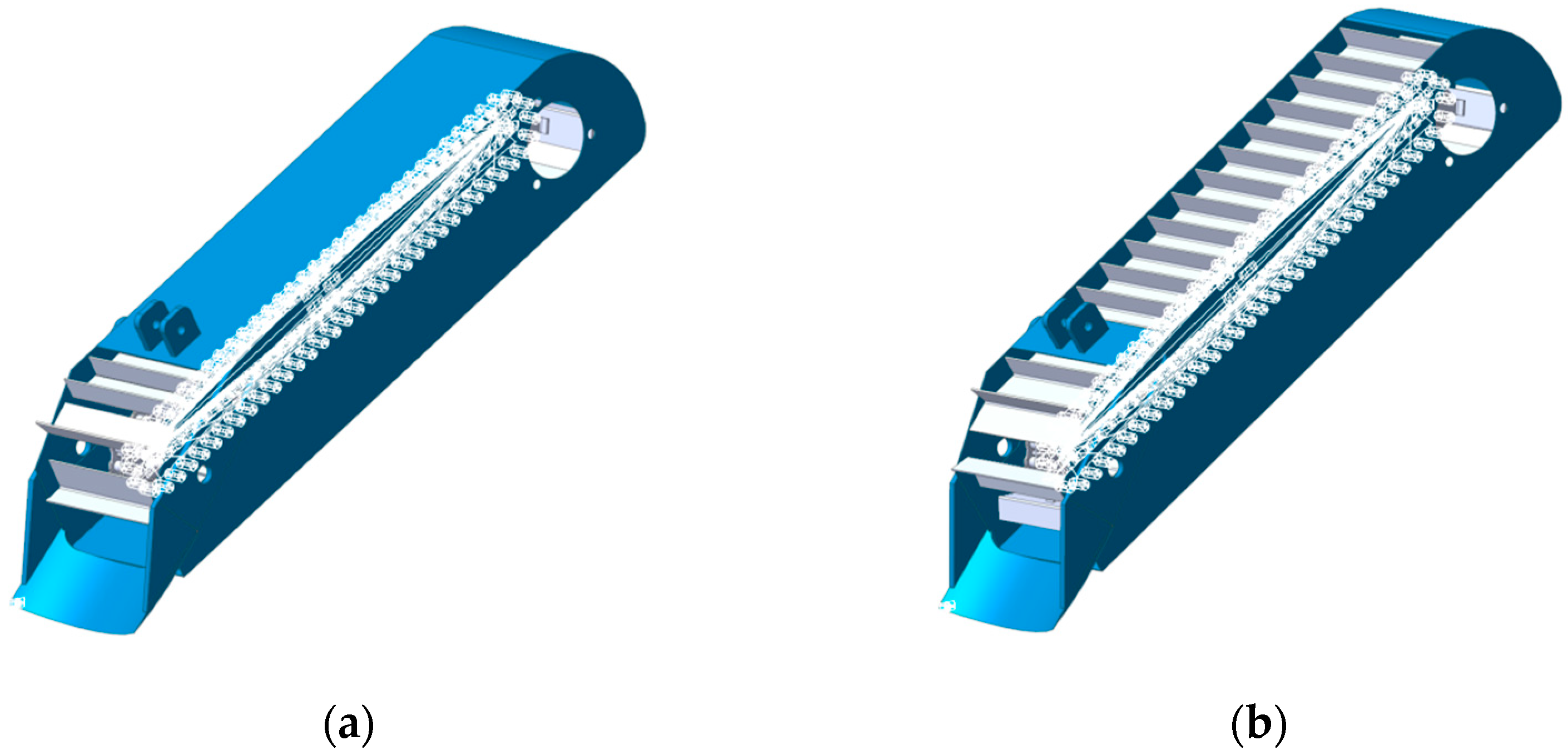
Combined with EDEM to simulate the soil covering simulation of the scraper lifting chain membrane mulching device before and after optimization, from the starting shovel crushing performance and soil quality to analyze and measure the effect of the improvement, the simulation results show that: the innovative design of the curved surface shovel soil upgrading effect is good. Applying the EDEM post-processing Selection module, it was calculated that the lower scraper conveyor soil flow rate was increased by a factor of three.
(3)
The results of the soil tank performance comparison test show that under the same soil conditions and operating parameters, the improved membrane mulching device has a simple structure, low power consumption, good working performance of all components, good soil crushing effect during planting operations, fast flow speed, test probability of congestion of about 10%, and low congestion, and the whole membrane surface mulching quantity has been improved by 47.5%. After optimization and improvement, the standard requirements of dryland potato seedling strip mulching planting technology on mulching parameters have been reached, and the innovative and optimized working structure combination is of great significance for dryland potato yield on the Loess Plateau.

Author Contributions

Methodology, H.Z. and W.S.; investigation, Y.L., Y.C. and W.X.; software, H.Z. and H.L. (Hongling Li); formal analysis, H.Z., X.L. and H.L. (Hui Li); resources, H.Z., W.S. and H.L. (Hongling Li); writing—original draft, Y.L., G.S. and W.X.; writing—review and editing, Y.L., H.Z. and H.L. (Hongling Li); funding acquisition, H.Z. and H.L. (Hui Li). All authors have read and agreed to the published version of the manuscript.

Funding

This work was supported by the National Natural Science Foundation of China Grant NSFC (52165028), the Gansu Provincial University Industry Support Plan (2022CYZC-42), the Self-Propelled Root and Tuber Harvester in Hilly and Mountainous Areas (GSAU-JSZR-2024-004), the Development and Demonstration of Transplanting and Harvesting Technology and Equipment for Long-Rooted Medicinal Herbs (2024CYZC-32), the Experimental Demonstration of Mechanized Planting and Harvesting Technology for Roots and Tubers of Chinese Medicinal Materials in Northwest Hilly Mountains (701-0722045), Gansu Provincial Education Department Innovation Fund Project (2022A-050), Northwest Chinese Herbal Medicine Whole Mechanization Research Base Project (2109-000000-20-01-199092), Agricultural Mechanization Science and Technology Project of Gansu Provincial Department of Agriculture and Rural Affairs (njyf2023-21-1), School-level Teaching Research Project of Gansu Agricultural University (GAU-JXYJ-2023-05), Self-listed Projects of Gansu Agricultural University (GSAU-ZL-2020-01, 02, 03), Modern Silk Road Cold and Arid Agriculture Science and Technology Support Project (GSLK-2022-12).

Institutional Review Board Statement

Not applicable.

Data Availability Statement

The original contributions presented in the study are included in the article.

Conflicts of Interest

The author declares no conflict of interest.

References

  1. Adekoya, O.B.; Oliyide, J.A.; Yaya, O.S.; Al-Faryan, M.A.S. Does oil connect differently with prominent assets during war? Analysis of intra-day data during the Russia-Ukraine saga. Resour. Policy 2022, 77, 102728. [Google Scholar] [CrossRef]
  2. Pereira, P.; Bašić, F.; Bogunovic, I.; Barcelo, D. Russian-Ukrainian war impacts the total environment. Sci. Total Environ. 2022, 837, 155865. [Google Scholar] [CrossRef]
  3. Khodadadi, A.; von Buelow, P. Design exploration by using a genetic algorithm and the Theory of Inventive Problem Solving (TRIZ). Autom. Constr. 2022, 141, 104354. [Google Scholar] [CrossRef]
  4. Wang, Y.; Wang, W.; Liu, J.; Li, Y.; Zhao, Y.; Liu, X.; Guan, L.; Liu, G. Chinese pepper picking tool designs and evaluations based on the TRIZ theory and the triangular fuzzy number. In Proceedings of the 2017 10th International Congress on Image and Signal Processing, BioMedical Engineering and Informatics (CISP-BMEI), Shanghai, China, 14–16 October 2017. [Google Scholar]
  5. Wang, J. Ecological Design of Silage Equipment Based on Innovative Method. Ph.D. Thesis, University of Jinan, Jinan, China, 2019. [Google Scholar]
  6. Wang, J.W.; Zhang, J.M. Gil-Lafuente. Research on Innovative Design and Evaluation of Agricultural Machinery Products. Math. Probl. Eng. 2019, 2019, 8179851. [Google Scholar] [CrossRef]
  7. Sun, W.; Liu, X.; Zhang, H.; Wang, H.; Tian, B. Design of potato casingsoil planter in all-in-one machine combined with fertilizing, sowing, ridging, complete film mulching and planting line covering. Trans. Chin. Soc. Agric. Eng. (Trans. CSAE) 2017, 33, 14–22, (In Chinese with English Abstract). [Google Scholar]
  8. Putri, N.T.; Sutanto, A.; Bifadhlih, N. The improvement of thresher design by using the integration of TRIZ and QFD approach. Int. J. Product. Qual. Manag. 2018, 25, 459–479. [Google Scholar] [CrossRef]
  9. Gao, G.; Ma, S. Improvement of transplanting manipulator for potted flower based on discrete element analysis and Su-field analysis. Editor. Off. Trans. Chin. Soc. Agric. Eng. 2017, 33, 35–42. [Google Scholar]
  10. Chen, S.; Kamarudin, K.M.; Yan, S. Analyzing the Synergy between HCI and TRIZ in Product Innovation through a Systematic Review of the Literature. Adv. Hum.-Comput. Interact. 2021, 2021, 6616962. [Google Scholar] [CrossRef]
  11. Luo, B.; Zhang, J. Design and Research of Prickly Pear Picking Machine Based on TRIZ and AD Theory. J. Agric. Mech. Res. 2023, 45, 24–29. [Google Scholar]
  12. Sauli, S.A.; Ishak, M.R.; Mustapha, F.; Yidris, N.; Hamat, S. Hybridization of TRIZ and CAD-analysis at the conceptual design stage. Int. J. Comput. Integr. Manuf. 2019, 32, 890–899. [Google Scholar] [CrossRef]
  13. Xing, H.; Gang, H.; Jia, D. Improved design and test on collecting wagon of rectangular bale based on ARIZ algorithm. Trans. Chin. Soc. Agric. Mach. 2016, 47, 254–260. [Google Scholar]
  14. Liu, A.; Lu, S.; Zhang, Z.; Li, T.; Xie, Y. Function recommender system for product planning and design. CIRP Ann.-Manuf. Technol. 2017, 66, 181–184. [Google Scholar] [CrossRef]
  15. Qu, H.; Shi, L.; Xin, S. Design and experiment of flax precision hole-seedind combined operation machine with soil storage device. J. China Agric. Univ. 2022, 27, 186–197. [Google Scholar]
  16. Shi, L.; Sun, W.; Zhao, W.; Yang, X.; Feng, B. Parameter determination and validation of discrete element model of seed potato mechanical seeding. Trans. Chin. Soc. Agric. Eng. (Trans. CSAE) 2018, 34, 35–42, (In Chinese with English Abstract). [Google Scholar]
  17. Shi, L.; Zhao, W.; Sun, W. Parameter calibration of soil particles contact model of farmland soil in northwest arid region based on discrete element method. Trans. Chin. Soc. Agric. Eng. (Trans. CSAE) 2017, 33, 181–187, (In Chinese with English Abstract). [Google Scholar]
  18. Liu, W.; He, J.; Li, H. Calibration of Simulation Parameters for Potato Minituber Based on EDEM. Trans. Chin. Soc. Agric. Mach. 2018, 49, 125–135+142. [Google Scholar]
  19. Dun, G.; Chen, H.; Ji, W. Finite element analysis of chisel-type deep shovel based on EDEM and SolidWorks Simulation. J. Henan Agric. Univ. 2017, 51, 678–682. [Google Scholar]
  20. Wang, X.; Hu, H.; Wang, Q. Calibration Method of Soil Contact Characteristic Parameters Based on DEM Theory. Trans. Chin. Soc. Agric. Mach. 2017, 48, 78–85. [Google Scholar]
  21. Sun, H. Design and Experimental Research on Transporting and Separating Device of Lifting Chain Potato Digger. Ph.D. Thesis, Northeast Agricultural University, Harbin, China, 2019. [Google Scholar]
  22. Wei, Z.; Han, M.; Su, G.; Zhang, H.; Li, X.; Jin, C. Design and Experiment of a Bagging and Unloading Potato Combine Harvester. Trans. Chin. Soc. Agric. Mach. 2023, 54, 92–104. [Google Scholar]
  23. Wang, X.; Yang, D.; Liu, M.; Li, Y.; Chen, X.Y.; Cheng, Z.W. Parameter Optimization and Experiment of Picking Device of Self-propelled Potato Collecting Machine. Trans. Chin. Soc. Agric. Mach. 2023, 54, 20–29. [Google Scholar]
  24. GB/T 25417-2010; Technical Specification of Quality Evaluation for Potato Planter. National Standards of the Republic of China: Beijing, China, 2010.
  25. NY/T 1415-2021; Technical Specification for Quality Evaluation of Potato Planters. National Agricultural Machinery Standardization Technical Committee Agricultural Mechanization Sub-Technical Committee: Beijing, China, 2021. Available online: https://www.chinesestandard.net/PDF/English.aspx/NYT1415-2021 (accessed on 1 April 2024).
  26. NY/T 987-2006; Operation Quality Grain Film-Covering Hill-Drop Dril. National Agricultural Machinery Standardization Technical Committee: Beijing, China, 2006. Available online: https://www.chinesestandard.net/PDF/English.aspx/NYT987-2006 (accessed on 1 April 2024).
Figure 1. Optimization flow chart.
Agriculture 14 01695 g001
Figure 2. Agronomic effect.
Agriculture 14 01695 g002
Figure 3. Schematic diagram of the working principle of the covering device on the spanning membrane: 1. Frame; 2. Screw conveyor; 3. Mulching on film; 4. Monopoly body; 5. Soil lifting mechanism; 6. Soil picking shovel; 7. Ground wheel; 8. Input axis.
Agriculture 14 01695 g003
Figure 4. Structure of spanning membrane mulching device: (a) axonometric drawing: 1. soil shovel; 2. scraping board; 3. transmission chain; 4. guide wheel; 5. soil lifting shell; 6. soil lifting device drive shaft; 7. soil transport box; 8. screw conveyor. (b) Starboard view.
Agriculture 14 01695 g004
Figure 5. Sketch of the force on the earth extraction shovel.
Agriculture 14 01695 g005
Figure 6. Flow of solving technical contradictions.
Agriculture 14 01695 g006
Figure 7. Working process diagram of the earth scraper.
Agriculture 14 01695 g007
Figure 8. Causal analysis.
Agriculture 14 01695 g008
Figure 9. “Object field model” analysis of soil shovel: (a) General Model; (b) Improved model.
Agriculture 14 01695 g009
Figure 10. Standard solution application for scraper lifting device: (a) upper scraping; (b) lower scraping.
Agriculture 14 01695 g010
Figure 11. (a) Upper scraping. 1. Soil; 2. Lifting shovel; 3. Driven wheel; 4. Scraper; 5. Lifting chain; (b) Lower scraping: 1. Soil; 2. Lifting shovel; 3. Driven wheel; 4. Scraper; 5. Lifting chain. Working principle of scraper lifting mechanism where ω is the angular velocity of the driven wheel, rad/s−1; v is the forward speed, ms−1; H is the depth of the soil, mm; γ is the angle between the ascending belt and the horizontal plane, (°); ψ is the angle of internal friction of the soil, (°); r is the radius of the driven wheel, mm; h is the height of the scraper, mm; l is the pitch of the scraper, mm; v′ is the speed of the ascending chain, m/s−1.
Agriculture 14 01695 g011
Figure 12. Model drawing of soil trench.
Agriculture 14 01695 g012
Figure 13. The 3D model of soil lifting device: (a) upper scraping; (b) lower scraping.
Agriculture 14 01695 g013
Figure 14. Multi-body dynamics model: (a) upper scraping; (b) lower scraping.
Agriculture 14 01695 g014
Figure 15. Modeling the coupling.
Agriculture 14 01695 g015
Figure 16. Simulation results of upper scraping soil lifting device.
Agriculture 14 01695 g016
Figure 17. Simulation results of lower scraping soil lifting device.
Agriculture 14 01695 g017
Figure 18. Velocity cloud of soil particles of upper scraping soil lifting device.
Agriculture 14 01695 g018
Figure 19. Velocity cloud of soil particles of lower scraping soil lifting device.
Agriculture 14 01695 g019
Figure 20. Cloud view of the direction of motion of soil particles in the upper scraping type.
Agriculture 14 01695 g020
Figure 21. Direction of movement of soil particles in the lower scraping soil lifting device.
Agriculture 14 01695 g021
Figure 22. Adding a flow sensor: (a) upper scraping; (b) lower scraping.
Agriculture 14 01695 g022
Figure 23. Flow–time plot.
Agriculture 14 01695 g023
Figure 24. Soil tank experiment.
Agriculture 14 01695 g024
Table 1. Conflict matrix for earth extraction shovels.
Improved ParametersDeteriorating Parameters
26 Quantity of a Substance or Thing
10 Force14 The principle of surfacing
29 Pneumatic and hydraulic construction principles
18 Principle of mechanical vibration
36 Phase change principle
Table 2. Summary ranking table of scenarios.
Program NumberProgram DescriptionSchemaProgrammatic EvaluationOrder
1The surface of the shovel is designed as a curved surface, which improves the damping performance and provides the effect of breaking up the soil.Agriculture 14 01695 i001Easy to implement, low cost.1
2Blowers are used to blow the soil into the scraper lift chain.Agriculture 14 01695 i002
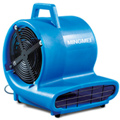
Replaced the source of the problem—earth extraction shovel—easy to implement, introduces new problems.3
3Vibrating motor to provide the excitation source for the shovel.Agriculture 14 01695 i003Easy to implement, slightly more expensive.2
4The vibration is realized by a crank linkage mechanism that drives the earth moving shovel in a reciprocating motion.Agriculture 14 01695 i004Relative complexity and introduction of new issues.4
Table 3. Mechanical properties of materials.
MaterialMaterial ParametersContact Parameters
Poisson RatioShear Modulus/MPaDensity
/(kg·m−3)
Collision FormRestitution
Coefficient
Static Friction
Coefficient
Dynamic Friction
Coefficient
Soil0.31002680Particle–Particle0.30.50.3
65Mn0.283.5 × 1047850Particle–Steel0.30.30.2
Steel0.251.0 × 1077800
Table 4. Soil particle cohesion parameters.
ParametersNumerical Value
Normal contact stiffness/(N·m2)108
Tangential contact stiffness/(N·m2)5 × 107
Critical normal stress/Pa30,000
Critical tangential stress/Pa15,000
Bonding radius/mm5.4
Table 5. Field trial results.
Test IndicatorsImproved Device Value/Mean DeviationOriginal Installation Value/Mean Deviation
Probability of machine congestion10%30%
Mulching of the entire membrane surface21.06 kg/1.06 kg14.27 kg/1.12 kg
Disclaimer/Publisher’s Note: The statements, opinions and data contained in all publications are solely those of the individual author(s) and contributor(s) and not of MDPI and/or the editor(s). MDPI and/or the editor(s) disclaim responsibility for any injury to people or property resulting from any ideas, methods, instructions or products referred to in the content.

