Review

Core Technologies of Sugarcane Chopper Harvester Extractor: A Critical Review

1
State Key Laboratory of Intelligent Agricultural Power Equipment, China Agricultural University, Beijing 100083, China
2
Sanya Institute, China Agricultural University, Sanya 572025, China
*
Author to whom correspondence should be addressed.
Agriculture 2024, 14(10), 1730; https://doi.org/10.3390/agriculture14101730
Submission received: 24 July 2024 / Revised: 18 September 2024 / Accepted: 26 September 2024 / Published: 1 October 2024
(This article belongs to the Section Agricultural Technology)

Abstract

:
This review has systematically assessed the critical technologies of impurity removal fans in segmental sugarcane harvesters, highlighting their impact on minimizing harvester impurity rates. The analysis was conducted from three perspectives: Firstly, the physical properties of flexible sheet-like materials were thoroughly examined, including the methodologies for material parameter measurement, the utilization of technical approaches, and the constraints of existing methods. Secondly, the operational mechanisms of impurity removal fans were elucidated, encompassing their working principles, research subjects, and technical methodologies, and compared with the mechanisms of analogous fluid machinery. Lastly, a review of the structural design and parameters of impurity removal fans was undertaken, analyzing the interplay between operational modes, structural optimization designs, and aerodynamic characteristics. The review identified key issues in the design and performance of impurity removal fans and recognized the challenges in technological advancement. Through this triadic analytical framework, the review has identified salient design and performance deficiencies within existing impurity expulsion fan technologies and has underscored the formidable challenges confronting technological evolution in this domain. Synthesizing these insights, the review proffered prospective research vectors and avant-garde technological interventions poised to augment the operational efficacy of impurity expulsion fans, with the overarching goal of enhancing the operational proficiency of sugarcane harvesting machinery.

1. Introduction

Sugarcane serves as the principal feedstock for sugar production in China, predominantly cultivated in regions such as Guangxi, Guangdong, Hainan, and Yunnan. The annual planting area spans approximately 1.33 million hectares, constituting over 85% of the total sugarcane cultivation area. Consequently, the sucrose yield from sugarcane represents more than 90% of the nation’s total sugar output [1,2,3]. The cultivation of sugarcane not only provides income for over 40 million farmers but also generates significant tax revenues for local governments in the major producing areas [4,5]. Furthermore, the Chinese government has placed a strong emphasis on the mechanization of sugarcane production. In recent years, the No. 1 Central Document has highlighted and directed the advancement of mechanized sugarcane harvesting, with the Ministry of Agriculture and Rural Affairs and other relevant ministries and commissions issuing guidelines to foster the development of mechanization in this sector [6,7,8].
In the context of mechanized sugarcane harvesting, achieving a high stripping rate is challenging, resulting in raw cane with a significant number of inclusions. The impurity rate of such harvested cane can reach 7% to 10%. In contrast, the domestic sugar industry mandates a stringent impurity rate for mechanically harvested raw cane, stipulating that it must not surpass 5.0%. Consequently, the elevated impurity rate of raw cane obtained through mechanical harvesting significantly influences the production costs of sugar manufacturing. This issue diminishes the enthusiasm of both sugar mills and cane farmers for adopting mechanized harvesting techniques, thereby hindering the widespread adoption of mechanized sugarcane harvesting in China. Consequently, reducing the inclusion content in mechanically harvested raw cane and enhancing its quality are pivotal for the successful implementation of mechanized sugarcane harvesting [9,10].
During the impurity removal process, both the cane sections and the cane leaves are simultaneously directed toward the impurity exhaust fan. Due to their lower suspension velocity, the leaves are propelled along the fan outlet direction by the wind pressure, whereas the sugarcane, with its higher suspension velocity, succumbs to gravity and descends directly into the collection box positioned beneath the excavator. The efficiency of the impurity exhaust fan is critical, as it significantly influences the impurity content and loss rate of the sugarcane, as well as the overall performance and adoption of the harvesting machinery. This mechanism is illustrated in Figure 1.
Currently, research on the impurity exhaust fan in sugarcane harvesters faces several challenges and gaps. The theoretical frameworks pertaining to these fans are underdeveloped. The dynamics of impurities within the fan are highly intricate, with the motion characteristics of the impurities and the aerodynamic properties of the internal flow field being key contributors to the elevated impurity content. This paper aims to provide a systematic review of the existing research on impurity exhaust fans, thereby offering a theoretical foundation for the optimization of their performance.

2. Research Ideas

As a pivotal component of sugarcane harvesters, the trash exhaust fan’s performance exerts a substantial influence on the impurity content and loss rate of sugarcane, which in turn directly affects the quality of the sugar produced and the income of farmers [11,12]. Numerous scholars have conducted research on the internal material characteristics and the parameters influencing the fan’s operation. However, the literature on the exhaust fan system as a whole is relatively scarce, resulting in a dearth of theoretical support for the structural enhancement of these fans. This paper aims to provide a comprehensive discussion, building upon the findings of previous research, as depicted in Figure 2.
The overall research ideas of the review are introduced:
(i)
Research on material characteristics: The development of a cleaning scheme and the establishment of an appropriate cleaning speed range are foundational for the structural design of impurity exhaust fans. Sugarcane leaves are classified as flexible flake materials, which are prevalent in the realm of agricultural material cleaning. The cleaning process predominantly employs the principle of gas–solid two-phase flow to facilitate the entry and removal of impurities. The CFD-DEM coupling method is widely utilized to address these dynamics, with the prerequisite of conducting parameter determination. Given the limitations inherent in this approach, several scholars have proposed innovative methods to overcome these challenges, thereby paving the way for further mechanistic research. This discussion will delve into these advancements and their implications for the design and optimization of impurity exhaust fans.
(ii)
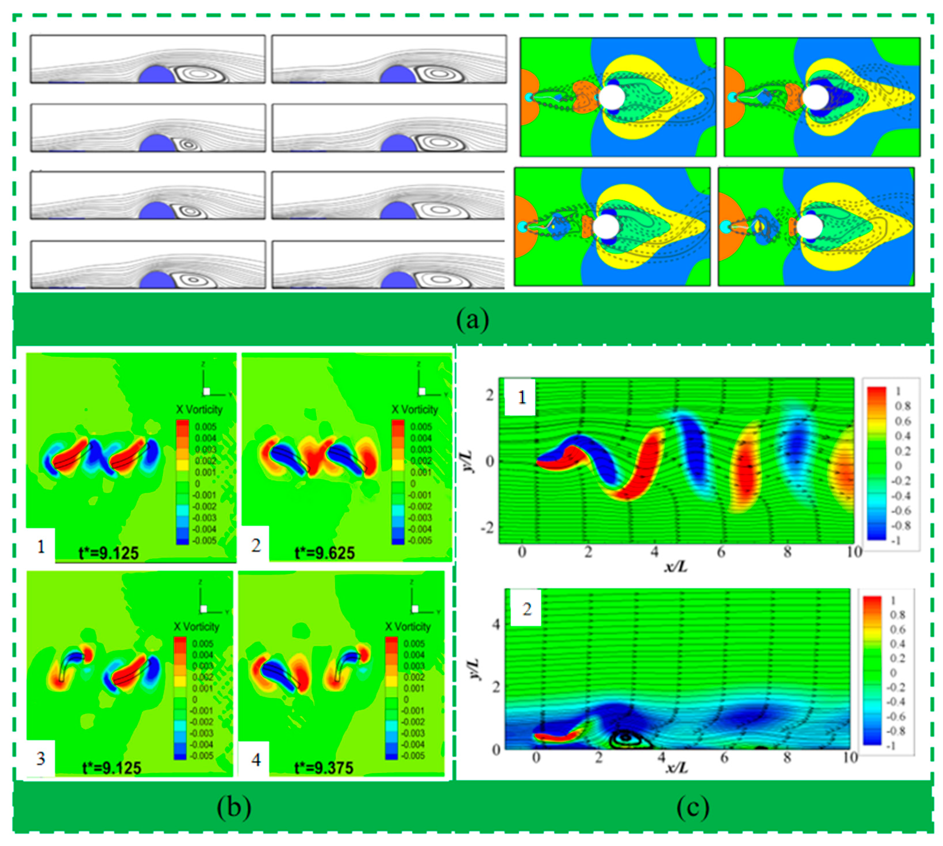
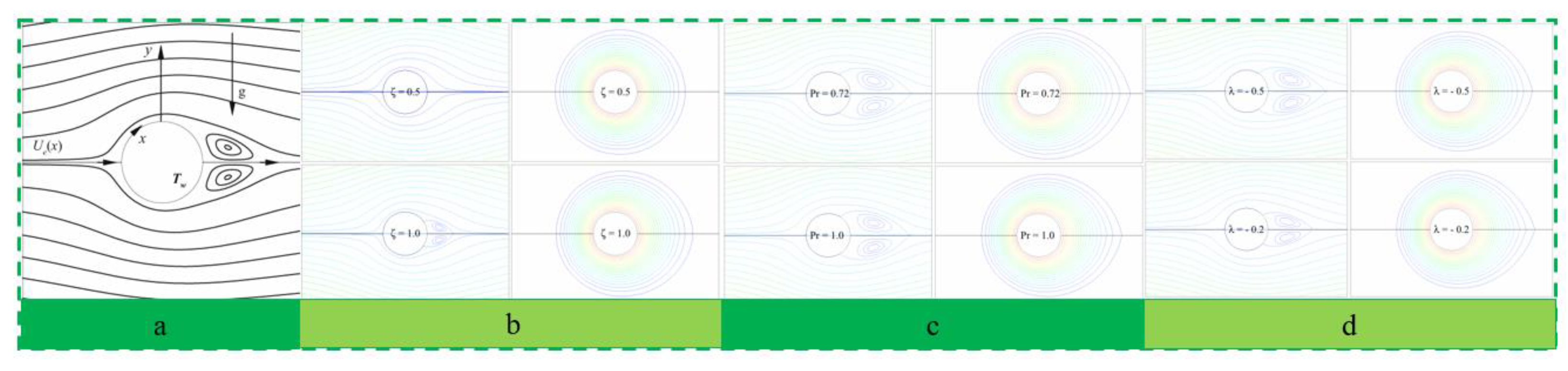
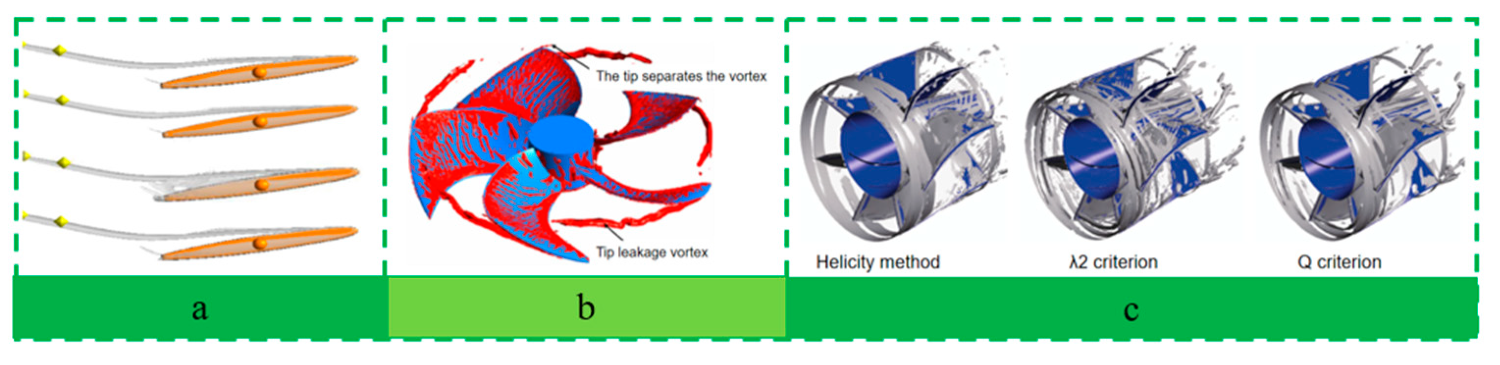
Mechanistic research on impurity emission: The impurity exhaust fan, a quintessential piece of fluid machinery, has received less mechanistic investigation compared to other fluid machinery such as industrial fans and aero engines, and it lacks a robust theoretical foundation. The foundation for defining the operating conditions and establishing optimal usage parameters for fluid machinery is a comprehensive understanding of its fluid mechanical characteristic curves. The flow state is an essential research subject in the optimization process of fluid machinery, with the boundary layer flow separation phenomenon being a key research focus. When examining the performance mechanisms of fluid machinery, eddy identification technology emerges as a principal investigative tool. The third segment of this study, which pertains to the structural and operational parameters of the fan, is informed and directed by the insights gained from mechanistic research. This approach ensures that the design and operational strategies for the impurity exhaust fan are grounded in a thorough understanding of its fluid dynamics and performance characteristics.
(iii)
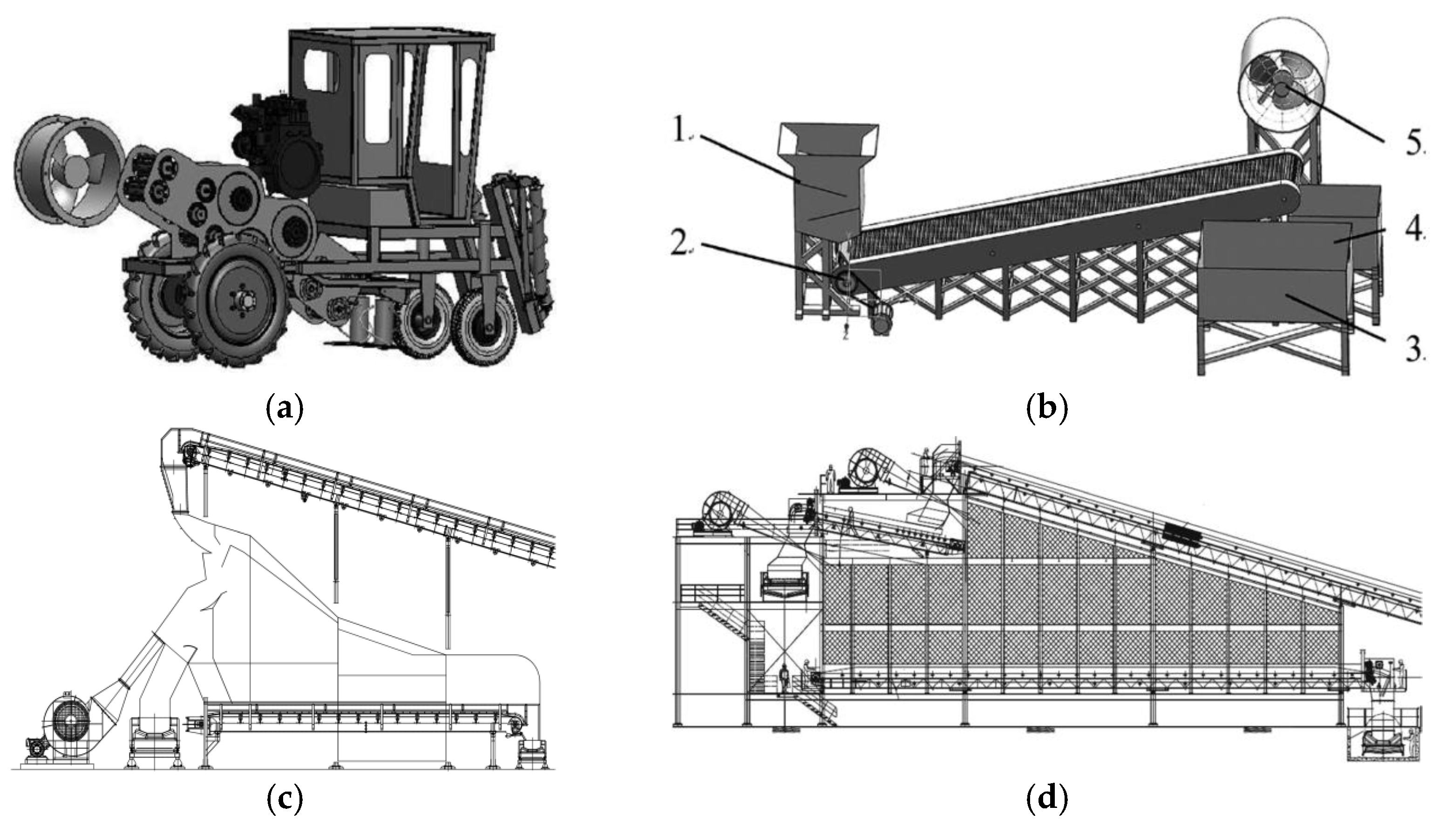
Investigation of fan structure and operating parameters: This study synthesizes the significant impact of the impurity exhaust fan’s structure and operating parameters on its impurity removal efficiency. The analysis is conducted from three perspectives: operating mode, structural parameters, and airflow field. The research on structural parameters primarily encompasses structural optimization, investigation of the airflow field, and comparative assessments of performance before and after structural modifications. The overarching goal of these investigations is to minimize the impurity content.
Finally, the study identifies existing challenges and proposes future research directions for the development of the sugarcane combine harvester, with a focus on enhancing the efficiency and effectiveness of impurity removal systems.

3. Material Characteristics

3.1. Material Research Methodology

Characterization of Sugarcane Impurities: Sugarcane impurities are classified as flexible heterotrophic materials, a category that is prevalent in agricultural production. Examples include the sorting of machine-harvested fresh leaves, separation of rice straw, drying of preserved fruits, tobacco curing, peel cleaning, forage grading, and more. The gas–solid two-phase flow dynamics of flexible, irregularly shaped materials present technical challenges and represent frontier issues in the advancement of agricultural machinery. Accurately predicting the trajectory and deformation of these materials in multiphase flows is crucial for the development of pneumatic separation, hot air drying, and pneumatic conveying technologies. Technological Approaches: Particle Image Velocimetry (PIV, Beijing, China) and high-speed camera technology (London, UK) have emerged as vital tools for examining the gas–solid two-phase flow of agricultural materials. Furthermore, the discrete element method (DEM) (EDEM 2022 Simulation Ltd., Edinburgh, UK), computational fluid dynamics (CFD) (Fluent 2022R1, ANSYS Inc., Canonsburg, PA, USA), and the coupled DEM-CFD approach have proven to be effective methodologies for studying the two-phase flow characteristics of flexible, irregularly shaped materials. These methods are instrumental in advancing the understanding and optimization of agricultural processes involving such materials.
However, in the field of sugarcane impurity removal, the CFD + DEM coupling method is rarely used to study the two-phase flow characteristics and operation mechanism, and the calibration and verification of the simulation parameters of materials is a prerequisite for studying the working effect of sugarcane impurity removal fan. The range of material suspension speed is the main basis for whether wind cleaning can be selected. When there is a large difference between the suspension velocity of impurities and the collected substances, it can effectively play the role of wind cleaning. At the beginning of the development of the cleaning equipment, the levitation speed was also used as a reference to set the wind speed range of the device. At present, the research on the determination of suspension velocity of agricultural materials mainly focuses on feed, grains, residual films, etc. [13,14,15]. In 2017, Yuan Chengyu et al. improved the sugarcane material suspension velocity measurement device (South China Agricultural University, Guangzhou, Guangdong, China), and added an auxiliary pull wire for suspending the cane section, and judged whether the material reached the suspension speed by measuring the tensile force of the pull wire under different wind speeds [16].
In 2018, Wang et al. engineered a device for measuring the suspension velocity of sugarcane materials (refer to Figure 3a). The measurement area of this device is strategically positioned upstream of the impeller to mitigate the rotational disturbances caused by air flow passing through the impeller, as depicted in Figure 3b. The authors categorized sugarcane impurities based on the ease with which they can be removed using wind cleaning methods. Among these, cane leaves were identified as the most readily removable, with light cane tips following suit, while heavy cane tips posed the greatest challenge for removal [17].
Wen Xiang et al. employed stacking angle testing and regression model predictions to calibrate parameters, which were subsequently utilized in simulations to estimate an impurity rate of 7.4%. This figure was found to be in close agreement with the 6.8% impurity rate observed in field experiments [18]. Guo Wuji et al. developed a simplified geometric model of the impurity removal device using Solid Works (2022) and ICEM (ANSYS ICEM Inc., Canonsburg, PA, USA), categorized the sugarcane material post-harvester cutting, and applied EDEM discrete element software for modeling and calibrating the discrete element parameters. They constructed a simulation model that integrates the impurity removal device, cane section, and crushed cane (cane tail) using the CFD + DEM + DE coupling method, which was subsequently validated through field trials [19]. Huang Shenchuang et al. utilized PRO/E software (5.0) to create a 3D model of sugarcane, which was then imported into ANSYS/LS-DYNA for finite element simulation. Based on the measured and inversely determined material parameters, they defined the material model for sugarcane and meshed the model to produce a finite element simulation model of the sugarcane stem and leaves [20]. Pu Minghui et al. suggested that the development of a sugarcane flexible body model is crucial for studying the virtual prototype of a small sugarcane harvester, which is a rigid–flexible coupled multi-body dynamic system. They established the sugarcane flexible body model using three methods within the multi-body dynamics framework of ADAMS software (I2.0): the discrete beam method, Flex method, and Auto Flex method. Their results indicated that the sugarcane model developed using the Flex method most closely approximated the theoretical values and experimental conditions [21].
Zhang Tao et al. applied orthogonal methods to determine the contact parameters essential for the discrete element simulation of corn stalks, calibrating these parameters based on their relative error in the radial packing angle, as depicted in Figure 4a [22]. In a similar vein, Liu Wenzheng et al. created a miniaturized potato model tailored to the material’s characteristics, utilizing a combination of experimental data and simulation to refine its discrete element parameters, as shown in Figure 4b [23]. They calibrated these parameters by adjusting independent variables within their simulation models to yield evaluation index values, which were then used to generate a curve equation. The experimentally measured values from various factors in their physical models were input into this equation to derive discrete element simulation parameters specific to the miniaturized potato model. These parameters were ultimately validated through simulated experiments.
For materials characterized by low density and small size, local features such as surface irregularities and nodes can significantly affect suspension velocity. Zewdu et al. observed that residual straw after grain cleaning typically possesses nodes and, thus, investigated the impact of node positioning on the suspension velocity of grain straw surfaces. Their findings revealed that straw with nodes exhibited higher suspension velocities than node-free straw, with the highest velocities occurring in straws with nodes at the end, followed by those with nodes in the middle, and straws without nodes registering the lowest suspension velocities [24]. In the context of walnut processing, Khir et al. examined the effect of walnut shells on suspension velocity to facilitate wind separation. Their study demonstrated a marked difference in suspension velocities between shelled and unshelled walnuts. Utilizing a wind speed of 10 m/s effectively achieved separation between the two types of walnuts [25]. These findings underscore the importance of considering material characteristics when designing wind separation processes for agricultural products.

3.2. Problems of Retention and New Approaches

In recent years, advancements in computational power and numerical calculation techniques have enabled researchers to model and numerically simulate the dynamics of tree canopies, flexible fibers, and flexible flake materials. Investigating the aerodynamic and fluid–structure interaction characteristics of leaves is particularly relevant for tree conservation, the design of biomimetic antennas, and the development of innovative technologies. Vogel S. [26] conducted experiments on leaves from acacia, black walnut, glossy hickory, red maple, tulipwood, and oak, observing that most leaves exhibited the capacity to shrink and deform under higher wind speeds (as illustrated in Figure 5b). The computational fluid dynamics software XFLOW (2022), which employs the lattice Boltzmann method, was utilized to analyze the drag characteristics of tree canopies at varying leaf area indices and wind speeds, as depicted in Figure 5a [27]. Yang Hui integrated numerical calculations with experimental tests to examine the flow field and aerodynamic characteristics of canopies, as shown in Figure 5c [28]. Jin Yuzhen et al. applied the compatible time integral and iterative coupling algorithm to investigate the tensile and bending motion characteristics, as well as the stress and motion behavior of fibers within the main nozzle of an air-jet loom [29]. Wu Zhenyu et al. explored the movement and joint formation mechanisms of flexible yarns during pneumatic yarn splicing. They numerically simulated the airflow field within the twisting cavity using a turbulence model, thereby elucidating the influence of airflow intensity on the deformation and motion patterns of single-ended free flexible yarns [30]. These studies collectively contribute to a deeper understanding of the complex interactions between materials and their environments in fluid dynamics contexts.
The Immersion Boundary–Lattice Boltzmann Method (IB-LBM) possesses several advantageous characteristics, including explicitness, scalability, parallel computation capabilities, model precision, and high efficiency. These attributes position the IB-LBM as a potent alternative to conventional computational fluid dynamics (CFD) methods, particularly in the numerical simulation of material deformation and motion. Rojas R. et al. [31] employed the immersion boundary-finite difference lattice Boltzmann method to numerically simulate the free-falling of a cylinder and assessed the feasibility of using IB-LBM for the numerical simulation of moving objects under high Reynolds numbers. Xia Z. et al. [32] combined the block structure lattice Boltzmann method with finite element techniques to numerically simulate the sedimentation process of a single elliptical particle in a gaseous fluid. This approach demonstrates the versatility of the IB-LBM in handling complex fluid–structure interaction problems, offering a robust framework for advancing the study of material dynamics in fluid environments.
The interaction between flexible sheet materials, such as flags and wings, and airflow represents a quintessential fluid–structure interaction challenge. Investigating these dynamics is particularly significant for the application of biomimicry principles. Hua R. et al. [33] utilized the Immersion Boundary–Lattice Boltzmann Method (IB-LBM) to analyze the behavior of circular flexible sheets in viscous fluids, uncovering a variety of deformation modes. Tang C. et al. [34] employed the Lattice Boltzmann Method (LBM) to examine the autonomous propulsion of a three-dimensional flapping flexible board, deriving the interplay between the aspect ratio, bending stiffness, and the propulsion speed and efficiency of the board. Wu J. et al. [35] numerically dissected the motion characteristics between a stationary cylinder and a flexible plate, mimicking the movement of a fish. Luo Y. et al. [36] applied the IB-LBM to numerically calculate the cruising speed, propulsion, and deformation traits of a self-oscillating flexible plate. Wang L. et al. [37] combined the IB-LBM with the Finite Element Method (FEM) to study the dynamics of parallel flags within a two-dimensional numerical solution domain. In their approach, the fluid and flag interactions were resolved using LBM and FEM, respectively, with the IB method addressing the fluid–structure interactions. Connell B. S. H., Kim H., and Kim D. et al. [38,39,40] explored the motion characteristics of flag-like structures actuated by a uniform incompressible viscous fluid in an unbounded domain. They established correlations between the Reynolds number, aspect ratio, dimensionless bending stiffness, and the system’s dynamics, flutter stability, and response characteristics. These collective studies underscore the distinctive advantages of LBM in numerically calculating gas–solid interactions involving flexible fibers, flags, and sheet structures, offering valuable insights for the numerical simulation of two-phase flow in applications such as cane leaf separation (Figure 6).

4. Mechanism of Impurity Removal

Currently, the research approaches for sugarcane harvester impurity exhaust fans primarily encompass the measurement and testing of impurity content, loss rate, wind speed, and other relevant indicators. While some scholars have delved into the mechanisms of impurity removal, the theoretical rigor of these studies is insufficient to robustly inform the design of impurity exhaust fans. Consequently, it is imperative to draw upon the relevant research findings from the broader field of fluid mechanics to enhance the understanding and development of these fans.
In the realm of fluid machinery selection and design, the operational conditions are typically established first, followed by the formulation of the most suitable usage parameters. The foundation of this process is a comprehensive fluid mechanical characteristic curve [41]. The flow pressure curve assists engineers in selecting the appropriate equipment based on predefined operating conditions. Concurrently, the flow efficiency curve directs the fluid machinery to operate at near-optimal efficiency [42]. Consequently, examining the characteristic curve of the exhaust fan is essential. Zhang Peng investigated the impact of various parameters, such as the hub-to-tip ratio, blade tip radial clearance, and blade installation angle, on the aerodynamic performance of fans, plotting the characteristic curves for each parameter [43]. Yang Mao et al. provided a comprehensive overview of wind speed power curve plotting methods, encompassing stochastic, parametric and non-parametric, and discrete approaches, to inform the modeling of wind turbine characteristic curves [44]. Ye et al. focused on the blade tip design of axial fans in power plants, comparing the performance implications of different blade tip shapes through flow efficiency and total pressure curves [45]. These studies collectively contribute to the understanding and optimization of fluid machinery performance.
The flow state is an essential research subject in the optimization of hydromechanical systems, with particular emphasis on the phenomenon of boundary layer flow separation [46,47,48]. In the flow regime, the velocity of fluid far from the wall is minimally influenced by viscosity and represents the velocity of the primary flow zone. In contrast, the fluid velocity near the wall is zero due to the viscous effects of the surface, necessitating the existence of a region between the wall and the main stream dominated by viscosity and characterized by a significant velocity gradient normal to the flow, known as the boundary layer [49]. As depicted in Figure 7, as viscous stress acts on the fluid flowing downstream along the wall, the velocity within the boundary layer diminishes, and the pressure increases. Under the influence of an adverse pressure gradient, the flow velocity further decreases, and eventually, the kinetic energy within the boundary layer is insufficient to sustain the fluid’s original flow direction. This results in a reversal of flow velocity in a region near the wall, leading to the formation of counterflow [50,51]. Concurrently, the countercurrent compresses the boundary layer into the main flow region, either increasing the boundary layer’s thickness or causing it to detach from the wall. The separated fluid is then entrained from its position near the wall and mixed with the main stream, with the pressure in the entire mixing region remaining essentially uniform [52,53].
To investigate the influence of fluid mechanical properties, Guo et al. focused on the side gap eddy current of a hydraulic mechanical airfoil, employing the Q isosurface, λ2, rotational strength, and helicity methods to analyze the eddy structure [54]. Liu Gang et al. examined the impact of blade tip winglets on the aerodynamic performance of axial fans by calculating the vortex distribution and strength around the impeller using the Q isosurface method. They elucidated the influence of blade tip winglets on aerodynamic characteristics, such as pressure gradients and flow separation, through the analysis of blade tip leakage vortex and separation vortex distributions [55]. Zhao Binjuan et al. applied the second-generation vortex identification method to study internal vortices in mixed-flow pumps. Their findings indicated that the second-generation method provides more detailed eddy structures than the first-generation approach. The Q isosurface was particularly effective and accurate in capturing vortex structures, minimizing the influence of shear layers [56]. The vortex structure, once freed from shear layer interference near the wall surface, was uniformly distributed across each flow channel. The leakage vortex at the blade tip matched the actual scenario with a clear boundary, demonstrating the Q criterion’s utility in identifying vortices within the internal flow field of rotating machinery, such as mixed-flow pumps. Wang Chen evaluated the eddy characteristics of the three-dimensional hydrofoil blade roof gap using various eddy identification methods. The vorticity estimation method and the pressure criterion method accurately depicted the leakage vortex and separation vortex near the blade roof gap but fell short of capturing the induced vortex. In contrast, the Q criterion and λ2 criterion yielded highly similar results and accurately captured the induced vortex [57]. Wang Bo et al., with the aid of the Q isosurface, revealed the relationship between the vortex structure near the compressor blade tip and unsteady flow. Their study showed that the blade tip’s leakage vortex could induce a new vortex post-rupture, indirectly affecting the adjacent channel. Under specific angles of attack, the leakage vortex may undergo spiral fragmentation or reverse vortex phenomena, leading to unsteady disturbances and periodic oscillations of the blade [58]. Yan et al. underscored the benefits of the second-generation eddy identification method, particularly in studying the vortex structure of the angular separation zone of airfoils. Initially, they used streamlined distribution mapping near the blade’s flow field, which incompletely revealed the angular vortex and wake vortex structures. Subsequent use of the Q equivalent for vortex identification in this region revealed complex three-dimensional structures near and downstream of the airfoil trailing edge, along with high-speed, large-scale turbulent coherent structures outside the angular separation zone [59]. Small-scale turbulent coherent structures were observed in the corner regions with lower velocities. Figure 8 synthesizes the eddy current identification methods from the aforementioned literature.

5. Structure and Parameter Optimization

5.1. Mode of Operation

Sugarcane extractors are divided into two main forms: “suction” and “blowing”. However, the existing impurity exhaust fans may struggle to effectively separate impurities during the “suction” process due to inadequate wind power, stemming from suboptimal structural design or air leakage. Consequently, researchers have explored alternative exhaust fan selections and exhaust modes. As depicted in Figure 9a, Wang Haibo et al. introduced a side-blown exhaust fan design, which reduces the travel distance of impurities and aligns their movement direction perpendicular to gravity. This design obviates the need for the fan to counteract the gravitational force on impurities, thereby promoting energy efficiency [60]. Zeng Lingchao et al. developed a platform for impurity removal, tailored for a segmented harvesting approach. In this method, the harvester initially performs root cutting and segment cutting, followed by the platform’s role in purging impurities from the sugarcane mixture post-segmentation [61]. As illustrated in Figure 9b, the platform’s central component is an axial flow fan similar to that in Wang Haibo’s research. Utilizing this “blow air” type fan for impurity removal minimizes the damage caused by collisions between cane segments and the fan impeller. However, the airflow behind the fan outlet may become turbulent due to the impeller’s rotation, potentially leading to non-uniform air distribution. Soares et al. investigated the segmented sugarcane impurity removal devices commonly utilized in Brazil, as shown in Figure 9c,d. These devices feature both upward and downward air blast configurations, employing centrifugal fans for impurity removal [62]. The downward air blast removal equipment, in particular, is more powerful, with the capacity to process over 500 tonnes per hour and achieve impurity rates between 15% and 20%.

5.2. Structural Parameters

The operational and structural parameters of the exhaust fan exert a significant influence on the airflow field, subsequently impacting the performance of impurity removal. Consequently, examining this relationship is of considerable importance. An increasing number of scholars have focused on optimizing and enhancing fan structures, including the impeller (with considerations for the blade’s tip structure and clearance, the presence of winglets, and the impeller’s front and rear edge parameters), the shroud, and the support frame. These efforts primarily aim to analyze the structural impact on the internal airflow dynamics, thereby ascertaining the optimal structural parameters.
Wang, Li, Ma, and Li examined the basic structure and design parameters of the extractor blades. However, the effect of extractor casing was not considered in the study [60]. Zhong et al. examined the stress and vibration of the impeller during the operation of the extractor, but the problem of reducing the impurity content and loss rate was not addressed [63]. The effect of the extractor casing was comprehensively considered by Xing, Ma, Wang, Bai, and Hu, whose study was aimed at reducing the impurity content and loss rate in Figure 10. The leading and trailing edges of the extractor blades were smoothly transitioned and the outlet chamber was designed in a cylindrical shape, which aligned the main shaft with the main stream direction of the airflow as a way to reduce energy losses. The design allowed the sugarcane billets to be less likely to collide with the blades, which reduced the loss rate by 6.48%, 14.77%, and 28.08% with low, medium, and high speeds, respectively [64].
Tip structure and clearance: Ye Xuemin et al. utilized Fluent for three-dimensional numerical simulations to assess fan performance across various tip designs. They analyzed how different tip structures affect the flow field and loss distribution within and adjacent to the clearance region. Their findings indicate that tip grooves disrupt the vorticity distribution in the gap, suppress the leakage flow development, diminish the mixing between the leakage flow and the main stream, and consequently reduce leakage losses [65]. In the same year, Ye Xuemin et al. introduced a double-fluted structure at the tips, which was found to effectively curb tip leakage flow and enhance impeller performance. They simulated fan performance under the original tip design and the double-fluted tip with three varying grooving depths, examining the alterations in the leakage flow field and loss distribution within the clearance [66]. These results are illustrated in Figure 11.
Apical winglets: To mitigate the aerodynamic losses and noise induced by leakage flow at the tips of axial fans, Liu et al. [55] employed biomimetic principles. Drawing inspiration from the wing’s fused tip winglet structure, they integrated the tip winglet design into the axial fan’s tip flow control. Their research, as depicted in Figure 12, concluded that the tip winglet structure significantly suppresses the growth of tip leakage vorticity and tip separation vorticity, thereby enhancing the fan’s aerodynamic performance.
Optimization of impeller parameters and blade edges: Xing Haonan et al. [67] employed the SST k-ω and realizable k-ε models to compute turbulence in two-dimensional (2D) and three-dimensional (3D) flow fields, respectively. Their findings revealed that the original blade design, characterized by a sharp profile from the leading edge to the trailing edge, resulted in higher energy losses. In contrast, a redesigned blade with a more streamlined leading and trailing edge profile led to enhanced total pressure efficiency, as demonstrated in Figure 13. Furthermore, Xing Haonan et al. [68] developed a computational fluid dynamics (CFD) model for the exhaust fan. They considered the blade installation angle (β), the number of blades (N), and the clearance ratio (G) as variables. Using the fan’s no-load wind speed at 1650 revolutions per minute (rpm) as a benchmark, they designed a Box–Behnken simulation test with three factors at three levels each. This approach facilitated the optimization of the impeller parameters, aiming to maximize the fan’s performance.
Serrated leading edge blade: Zhang Xin [69] developed a serrated leading-edge structure by material removal from the tip to one-third of the blade root of the prototype fan’s blade. This modification aimed to optimize the blade design. Numerical simulations were conducted at the rated flow point, comparing the performance of the serrated leading-edge blades with varying serration sizes to that of the prototype fan. These simulations were applied to the impellers at different stages of the fan. Employing the Q criterion, vortex strength analysis, broadband noise analysis, and entropy generation analysis, Zhang Xin evaluated and compared the effects of the serrated leading-edge structure on the internal flow field and acoustic field within the fan. The study also delved into the underlying causes of any observed changes. Ultimately, the structural integrity of the blade was verified through fluid–structure interaction analysis, as illustrated in Figure 14.
Through the fusion of a leading-edge sawtooth design with winglet characteristics, a novel sawtooth blade configuration has been engineered. Subsequent to this design, the aerodynamic flow field, acoustic characteristics, and mechanical stress of the blades were analyzed. The research findings indicate that the introduction of a zigzag leading-edge significantly diminishes the vortex core distribution associated with trailing edge vortex shedding when compared to traditional straight-edge blades. This design modification is thus shown to be effective in reducing the aerodynamic losses and noise generation typically associated with such vortices.
Fairing Optimization: Huang Haihong et al. [70] conducted simulations and experimental tests to determine the optimal radial clearance between the fan blades and the fan casing, as well as the distance between the end face of the fan outlet hub and the fan outlet end face. Their findings confirmed that an outlet blade tip clearance of 2 mm maximizes the flow rate at the axial fan outlet while minimizing aerodynamic losses. Shen Jiang et al. [71] developed an enhanced inlet and outlet shape model for simulation analysis. They investigated the variation in axial fan air volume with respect to the radial dimensions of the inlet and outlet deflector, comparing the effects of two different outlet shapes on the fan’s air volume. Furthermore, they dissected the reasons behind the improved performance of the axial fan following the optimization of the deflector design. This research underscores the importance of fairing in enhancing fan efficiency and performance.

6. Conclusions and Recommendations

6.1. Research Status and Problems

In the domain of material characteristics research, the physical attributes of sugarcane have been subject to scrutiny, with a focus on parameters such as suspension velocity, relaxation time, slip rate, and mechanical equilibrium. Despite advancements, there remains a significant gap in the development of comprehensive models and in the integration of CFD-DEM simulations. The calibration of simulation parameters is an area that is underexplored, and there is a recognized need for refinement of contact and material models to enhance the accuracy and applicability of these models.
Regarding the study of fan structure and parameters, the preponderance of research has concentrated on the positioning of the impeller, the geometric characteristics of the blade’s leading and trailing edges, and the operational mechanisms of the primary and secondary stages of impurity removal. In contrast, there is a paucity of research pertaining to the fan’s top structure, clearance dimensions, and blade configuration. The operational modes of the fans are predominantly singular, typically employing a combination of suction and blowing functions.
In the investigation of the impurity emission mechanism, it is noted that while the impurity expulsion fan is a quintessential piece of fluid machinery, its mechanistic research is not as extensive as that of other fluid machinery, such as industrial fans and aero engines. There is a dearth of theoretical frameworks, particularly in the realms of eddy identification technology, boundary layer flow dynamics, and bidirectional coupling phenomena, which are critical for advancing the understanding and performance of these systems.

6.2. Research Development and Recommendations

The construction of robust contact and material models for sugarcane is essential, necessitating an in-depth investigation into the parameters that govern these models. Advancing the frontiers of modeling and achieving a seamless integration with CFD-DEM simulations will be pivotal for enhancing the predictive capabilities and accuracy of these models.
To diversify the operational modalities of the impurity exhaust fan, it is imperative to transcend the conventional paradigms of “suction” and “blowing” configurations. The exploration of innovative impurity removal mechanisms should be pursued, potentially drawing inspiration from biomimetic principles. This could involve the optimization of the blade top structure, clearance dimensions, and blade geometry to enhance the fan’s efficiency and adaptability.
Incorporating state-of-the-art turbulent down-vortex structures and eddy identification technologies is crucial for the field of sugarcane material impurity discharge. The adoption of advanced vortex identification methodologies, such as the third-generation LUTEX technology, will provide a more nuanced understanding of flow dynamics. Additionally, the application of boundary layer flow mechanisms and bidirectional coupling mechanisms will be instrumental in refining the theoretical underpinnings of impurity expulsion processes, leading to more effective design and operational strategies for sugarcane harvesting equipment.

Author Contributions

Conceptualization, W.L. (Weiqing Li) and S.M.; methodology, W.L. (Weiqing Li) and S.M.; software, W.L. (Weiqing Li) and W.L. (Wenzhi Li); validation, B.Z. and W.L. (Weiqing Li); formal analysis, W.L. (Weiqing Li) and J.Q.; investigation, W.L. (Weiqing Li) and P.H.; resources, W.L. (Weiqing Li) and B.Z.; data curation, W.L. (Weiqing Li) and S.M.; writing—original draft preparation, W.L. (Weiqing Li) and S.M.; writing—review and editing, W.L. (Weiqing Li) and P.H.; visualization, W.L. (Weiqing Li) and S.M.; supervision, W.L. (Weiqing Li); project administration, S.M.; funding acquisition, S.M. All authors have read and agreed to the published version of the manuscript.

Funding

The research presented in this paper was partially supported by the Portable Sugarcane Harvester Research and Development (NK2022160504), the National Natural Science Foundation of China (Grant No. 32071916), the Guangxi Sugarcane Science and Technology Project (2022AA01010), the Guangxi Innovation-Driven Development Project (Guike AC22080001), the Hainan Natural Science Foundation Innovative Research Team Project (322CXTD521), the 2115 Talent Development Program of China Agricultural University Yunnan Zhenkang Professor Workstation Grant, and the Chinese Universities Scientific Fund (2022TC169). Any opinions, findings, and conclusions expressed in this paper are those of the authors and do not necessarily reflect the views of the CAU (China Agricultural University).

Institutional Review Board Statement

Not applicable.

Data Availability Statement

The data presented in this study are available on request from the corresponding author.

Conflicts of Interest

The authors declare no conflicts of interest.

References

  1. Liu, Q.; Mo, J.; Li, T.; Ou, Y.-G. Current situation of sugarcane planter and its key technical issues in China. Sugarcane Canesugar 2011, 5, 52–58. [Google Scholar]
  2. Wei, F.; Wei, J.; Du, G. Analysis of the development status and countermeasures of mechanization of sugarcane production. China Agric. Inf. 2015, 11, 148–149. [Google Scholar]
  3. Liu, X.; Zhang, C.; Zheng, C. Policy Development and Enlightenment of Brazilian Sugar Industry. In Proceedings of the 15th Symposium of the Sugarcane Committee of the Crop Science Society of China, Haikou, China, 1 August 2014; pp. 238–244. [Google Scholar]
  4. Zhang, H.; Luo, J.; Yang, Y.; Lin, Z. An Analysis of the Labor Force in the Sugarcane Region of Guangxi. Sugarcane Canesugar 2011, 4, 87–90. [Google Scholar]
  5. Tan, J.; Yang, S. Research on the development of mechanization of sugarcane production in Guangxi. J. South Agric. Sci. 2018, 391, 194–199. [Google Scholar] [CrossRef]
  6. Zhang, Z. Ministry of Agriculture: Implement the No. 1 Document of the Central Committee to improve the level of agricultural mechanization. South China Agric. Mach. 2016, 2, 4. [Google Scholar]
  7. Wang, W. Research on the Trend of China’s Three Rural Policies since the 21st Century: A Review and Prospect of 14 “Central No. 1 Documents”. Jiangxi Soc. Sci. 2017, 7, 51–58. [Google Scholar]
  8. Chen, W. Changes and future trends of the “three rural” policies in the No. 1 document of the Central Committee. Rural Econ. 2017, 8, 13–19. [Google Scholar]
  9. Mo, J.; Liu, Q. Discussion on mechanization technology of sugarcane harvesting in China. Agric. Mech. Res. 2013, 3, 12–18. [Google Scholar] [CrossRef]
  10. Tang, X. Effect of Leaf Stripping Drum Speed on Sugarcane Leaf Stripping Machine with Spring Leaf Stripping Element. Mach. Tool Hydraul. 2018, 46, 29–33. [Google Scholar] [CrossRef]
  11. Xie, F.; Ou, Y.; Liu, Q.; Feng, J.; Huang, S. High-speed photographic analysis of internal logistics and impurity removal in a whole straw sugarcane harvester. J. Agric. Mech. Res. 2015, 37, 203–206. [Google Scholar] [CrossRef]
  12. Wen, X.; Yang, J. Analysis of the current situation and problems of impurity removal devices in sugarcane harvesting machinery in China. Agric. Mach. Use Maint. 2019, 2, 80. [Google Scholar] [CrossRef]
  13. Shao, K.; Niu, Z.; Yu, C.; Wu, W. Determination and analysis of suspension velocity of aquatic pellet feed. Rev. Agric. Sci. Technol. 2022, 24, 120–129. [Google Scholar] [CrossRef]
  14. Kang, J.; Zhang, H.; Zhang, G.; Du, H.; Peng, Q.; Song, Y. Aerodynamic Characteristics of Residual Film Materials and Test of Membrane Miscellaneous Separation Device. Chin. J. Agric. Mach. 2020, 41, 167–172. [Google Scholar] [CrossRef]
  15. Hu, C.; Fang, X.; Shi, Y. Design and test of pneumatic fertilization device in paddy field. Chin. J. Agric. Mech. Chem. 2022, 43, 14–19+32. [Google Scholar] [CrossRef]
  16. Yuan, C.; Ou, Y.; Liu, Q.; Huang, Z. Suspension properties of a sliced sugarcane mixture. Jiangsu Agric. Sci. 2017, 45, 166–168. [Google Scholar] [CrossRef]
  17. Wang, F.; Yang, G.; Ke, W.; Ma, S. Studies on suspension property of sugarcane components. IFAC-PapersOnLine 2018, 51, 526–531. [Google Scholar] [CrossRef]
  18. Wen, X.; Yang, W.; Guo, W.; Zeng, B. Calibration and verification of simulation parameters of discrete element discharge of segmented sugarcane harvester. Chin. J. Agric. Mech. 2020, 41, 12. [Google Scholar] [CrossRef]
  19. Guo, W.; Yang, W.; Wen, X.; Yang, J.; Mo, J.; Zeng, B.; Nong, H. Research on simulation modeling method of impurity discharge of segmented sugarcane harvester. Agric. Mech. Res. 2020, 8, 6–12. [Google Scholar] [CrossRef]
  20. Huang, S.; Yang, W.; Yang, J.; Liang, L. Study on finite element modeling method of sugarcane stem-cane leaf system. Agric. Mech. Res. 2018, 40, 19–23. [Google Scholar] [CrossRef]
  21. Pu, M.; Wu, J. Modeling of sugarcane flexible body model based on ADAMS. J. Syst. Simul. 2009, 7, 1930–1932. [Google Scholar] [CrossRef]
  22. Zhang, T.; Liu, F.; Zhao, M.; Ma, Q.; Wang, W.; Fan, Q.; Yan, P. Determination of physical parameters of corn straw contact and calibration of discrete element simulation. J. China Agric. Univ. 2018, 23, 120–127. [Google Scholar] [CrossRef]
  23. Liu, W.; He, J.; Li, H.; Li, X.; Zheng, K.; Wei, Z. Parameter calibration of micro-potato simulation based on discrete elements. Trans. CSAM 2018, 49, 125–135. [Google Scholar] [CrossRef]
  24. Zewdu, A.D. Aerodynamic properties of tef grain and straw material. Biosyst. Eng. 2007, 98, 304–309. [Google Scholar] [CrossRef]
  25. Khir, R.; Pan, Z.; Atungulu, G.G.; Thompson, J.F. Characterization of physical and aerodynamic properties of walnuts. Trans. ASABE 2014, 57, 53–61. [Google Scholar] [CrossRef]
  26. Vogel, S. Drag and reconfiguration of broad leaves in high winds. J. Exp. Botany. 1989, 40, 941–948. [Google Scholar] [CrossRef]
  27. Zhang, K.; Fu, H. Resistance characteristics of three-dimensional virtual canopy based on lattice-Boltzmann method. J. Donghua Univ. (Nat. Sci. Ed.) 2019, 45, 306–312. [Google Scholar]
  28. Yang, H.; Fu, H. Numerical Simulation and Experimental Study of Tree Canopy Flow Resistance Characteristics. J. Cent. South Univ. (Nat. Sci. Ed.) 2016, 47, 4292–4300. [Google Scholar] [CrossRef]
  29. Jin, Y.; Li, J.; Lin, P.; Wu, J. Numerical Simulation of Coupling of Fiber and Airflow. J. Text. Res. 2015, 36, 152–157. [Google Scholar] [CrossRef]
  30. Wu, Z.; Shi, P.; Hu, X. Study on the filament motion and joint forming mechanism in the pneumatic yarn splicing process. Text. Res. J. 2016, 86, 2000–2012. [Google Scholar] [CrossRef]
  31. Rojas, R.; Hayashi, K.; Seta, T.; Tomiyama, A. Numerical simulation of flows about a stationary and a free-falling cylinder using immersed boundary-finite difference lattice Boltzmann method. J. Comput. Multi. Flow 2013, 5, 27–41. [Google Scholar] [CrossRef]
  32. Xia, Z.; Connington, K.; Rapaka, S.; Yue, P.; Feng, J.J.; Chen, S. Flow patterns in the sedimentation of an elliptical particle. J. Fluid Mech. 2009, 249, 249–272. [Google Scholar] [CrossRef]
  33. Hua, R.; Zhu, L.; Lu, X. Dynamics of fluid flow over a circular flexible plate. J. Fluid Mech. 2014, 759, 56–72. [Google Scholar] [CrossRef]
  34. Tang, C.; Lu, X. Self-propulsion of a three-dimensional flapping flexible plate. J. Hydrodyn. Ser. B 2016, 28, 1–9. [Google Scholar] [CrossRef]
  35. Wu, J.; Shu, C.; Zhao, N. Numerical study of flow control via the interaction between a circular cylinder and a flexible plate. J. Fluid. Struct. 2014, 49, 594–613. [Google Scholar] [CrossRef]
  36. Luo, Y.; Wu, T.H.; Qi, D. Lattice-Boltzmann lattice-spring simulations of flexibility and inertial effects on deformation and cruiing reversal of self-propelled flexible swimming bodies. Comput. Fluids 2017, 87, 87–102. [Google Scholar] [CrossRef]
  37. Wang, L.; Tian, F. Numerical simulation of flow over a parallel cantilevered flag in the vicinity of a rigid wall. Phys. Rev. E 2019, 99, 053111. [Google Scholar] [CrossRef]
  38. Connell, B.S.H.; Yue, D.K.P. Flapping dynamics of a flag in a uniform stream. J. Fluid Mech. 2007, 581, 33–67. [Google Scholar] [CrossRef]
  39. Kim, H.; Kang, S.; Kim, D. Dynamics of a flag behind a bluff body. J. Fluid. Struct. 2017, 71, 1–14. [Google Scholar] [CrossRef]
  40. Kim, D.; Cossé, J.; Cerdeira, C.H.; Gharib, M. Flapping dynamics of an inverted flag. J. Fluid Mech. 2013, 736, R1. [Google Scholar] [CrossRef]
  41. Zhang, K. Principles of Fluid Mechanics; China Machine Press: Beijing, China, 2000. [Google Scholar]
  42. Han, J. Surge analysis and preventive measures of mine axial flow fan. Min. Equip. 2020, 1, 100–101. [Google Scholar]
  43. Zhang, P. Optimization Design of Structural Parameters of Axial Fan; Yanshan University: Qinhuangdao, China, 2016. [Google Scholar]
  44. Yang, M.; Yang, Q. A review on the modeling of wind speed-power characteristic curves of wind turbines. Electr. Power Autom. Equip. 2018, 38, 34–43. [Google Scholar] [CrossRef]
  45. Ye, X.; Zhang, J.; Li, C. Simulation of blade tip grooving effect on performance of twin-stage variable-pitch axial fan. J. Syst. Simul. 2018, 30, 1511–1519. [Google Scholar] [CrossRef]
  46. Wangsawijaya, D.D.; Hutchins, N. Investigation of unsteady secondary flows and large-scale turbulence in heterogeneous turbulent boundary layers. J. Fluid Mech. 2022, 934, 440. [Google Scholar] [CrossRef]
  47. Mehmood, A.; Shah, B.H.; Usman, M.; Raza, I. Calculation of flow separation in a retarded boundary-layer over a moving continuous sheet. Phys. Scr. 2021, 96, 12. [Google Scholar] [CrossRef]
  48. Hanif, H. A computational approach for boundary layer flow and heat transfer of fractional Maxwell fluid. Math. Comput. Simulat. 2022, 191, 1–13. [Google Scholar] [CrossRef]
  49. Loper, D.E. Turbulent boundary-layer flow beneath a vortex. Part 1. Turbulent Bödewadt flow. J. Fluid Mech. 2020, 892, A12. [Google Scholar] [CrossRef]
  50. Schrichtin, X.Y.; Kestin, J. Boundary Layer Theory; McGraw-Hill: New York, NY, USA, 1961. [Google Scholar]
  51. Wen, S. Microfluidic Boundary Layer Theory and Its Application; Metallurgical Industry Press: Beijing, China, 2002. [Google Scholar]
  52. Qu, X.; Zhang, Y.; Lu, X.; Zhu, J.; Zhang, Y. Unsteady fluidic oscillators for active controlling boundary layer separation in an ultra-high-lift low-pressure turbine. Aerosp. Sci. Technol. 2021, 119, 1071300. [Google Scholar] [CrossRef]
  53. Nepal, C.R.; Rahman, T.; Parvin, S. Boundary-Layer Separations of Mixed Convection Flow Past an Isothermal Circular Cylinder. Int. J. Appl. Comput. Math. 2019, 5, 3. [Google Scholar] [CrossRef]
  54. Guo, C.; Huang, X.; Qiu, B.; Feng, X. Application and evaluation of eddy criterion in eddy current analysis of wing end clearance. J. Huazhong Univ. Sci. Technol. (Nat. Sci. Ed.) 2018, 46, 23–28. [Google Scholar] [CrossRef]
  55. Liu, G.; Wang, L.; Liu, X. Numerical study on the effect of bladelet winglets on the aerodynamic performance and noise characteristics of axial fans. J. Xi’an Jiaotong Univ. 2020, 54, 104–112. [Google Scholar] [CrossRef]
  56. Zhao, B.; Xie, Y.; Liao, W.; Han, L.; Fu, Y.; Huang, Z. Applicability analysis of the second-generation vortex identification method in the internal flow field of mixed-flow pumps. J. Mech. Eng. 2020, 56, 216–223. [Google Scholar] [CrossRef]
  57. Wang, C. Analysis and Control of Flow Characteristics of Three-Dimensional Hydrofoil Blade Top Gap. Master’s Thesis, Xi’an University of Technology, Xi’an, China, 2019. [Google Scholar]
  58. Wang, B.; Wu, Y. Vortex dynamics mechanism of unsteady flow at the tip of a diffused blade grid. Acta Aeronaut. Sin. 2020, 41, 246–262. [Google Scholar] [CrossRef]
  59. Yan, H.; Liu, Y.; Li, Q.; Lu, L. Turbulence characteristics in corner separation in a highly loaded linear compressor cascade. Aerosp. Sci. Technol. 2018, 75, 139–154. [Google Scholar] [CrossRef]
  60. Wang, H.; Li, S.; Ma, F.; Li, Z. Pneumatic design of impurity removal fan for small sugarcane harvester. Agric. Mech. Res. 2015, 37, 103–107. [Google Scholar] [CrossRef]
  61. Zeng, L.; Cao, Y.; Zhong, X.; Wang, W.; Huang, W. Design of sugarcane stem and leaf separator. South China Agric. Mach. 2021, 52, 36–38+44. [Google Scholar]
  62. dos Santos Penteado Soares, C.C.; Okuno, F.M.; Garbellini Duft, D.; Carvalho, D.J.; Morandi, J.; Guizelini Júnior, P.C.; Trez, C.R.; Eduardo, P.; Mantelatto Lima Verde Leal, M.R. Commercial Sugarcane Dry Cleaning Systems in Brazil: Progress and Challenges. BioEnergy Res. 2019, 12, 920–929. [Google Scholar] [CrossRef]
  63. Zhong, J.; Li, S.; Ma, F.; He, Y.; Pan, Y.; Sun, T.; Li, Z. Stress-strain and model analysis on impurity removal fan based on fluid-structure interaction. J. Agric. Mech. Res. 2017, 39, 6. [Google Scholar] [CrossRef]
  64. Xing, H.; Ma, S.; Wang, F.; Bai, J.; Hu, J. Structure optimization and experiment of sugarcane chopper harvester extractor. Trans. CSAE 2020, 36, 67–75. [Google Scholar] [CrossRef]
  65. Ye, X.; Li, P.; Li, C. Numerical study on the effect of blade top slotting on the performance of axial fans. Chin. J. Electr. Eng. 2015, 35, 652–659. [Google Scholar] [CrossRef]
  66. Ye, X.; Li, P.; Li, C. Study on the performance and vibration characteristics of axial fans under double-groove blade top structure. J. Mech. Eng. 2015, 51, 167–174. [Google Scholar] [CrossRef]
  67. Xing, H.; Ma, S.; Li, W.; Wang, F.; Bai, J.; Hu, J. Improving the performance of a sugarcane harvester extractor using design changes validated by computational fluid dynamic modelling and experiment. Biosystems Eng. 2022, 218, 124–138. [Google Scholar] [CrossRef]
  68. Xing, H.; Ma, S.; Mo, J.; Zeng, B.; Liang, W.; Li, W.; Wang, F.; Bai, J.; Ding, Z. Optimization and experiment of parameters for the impeller structure of extractor in a sugarcane chopper harvester. Trans. CSAE 2021, 37, 12–19. [Google Scholar] [CrossRef]
  69. Zhang, X. Study on the Influence of Blade Shape on the Performance of Axial Fan. Master’s Thesis, Taiyuan University of Technology, Taiyuan, China, 2021. [Google Scholar]
  70. Huang, H.; Lu, Y. Research on Effect of Blade Tip Clearance and Installation Position of Guide Vane on Flow Field of Axial-flow Fan. Fluid Mach. 2018, 46, 34–39. [Google Scholar]
  71. Shen, J.; Wang, B.; Li, K. Simulation study on the influence of shallow structure parameters on the performance of axial fans. Low Temp. Superconduct. 2019, 2, 91–95. [Google Scholar] [CrossRef]
Figure 1. Schematic diagram of the structure of the sugarcane chopper harvester extractor: (a) concrete figure; (b) process of impurity removal.
Agriculture 14 01730 g001
Figure 2. Overall research ideas for the extractor.
Agriculture 14 01730 g002
Figure 3. Measuring device and material suspension speed designed by [17]: (a) Measuring device, (b) Sugarcane material suspension rate.
Agriculture 14 01730 g003
Figure 4. Material research methodology: (a) Corn modeling [22], (b) Potato modeling [23], (c) Sugarcane modeling [19].
Agriculture 14 01730 g004
Figure 5. Numerical computational study of motion characteristics: (a) Influence of tree canopy on air flow resistance characteristics [27], (b) The drag-reducing capacity of leaves [26], (c) Internal flow characteristics of the canopy [28].
Agriculture 14 01730 g005
Figure 6. Typical fluid–solid coupling phenomenon for flexible sheet materials: (a) Motion characteristics between a cylinder and a flexible plate [35], (b) Self-excited oscillating flexible boards [36], (b1): The vorticity contours in the X-direction at t = 9.125. (b2): The vorticity contours in the X-direction at t = 9.625. (b3): The vorticity contours perpendicular to the X-direction at t = 9.125. (b4): The vorticity contours perpendicular to the X-direction at t = 9.375. (c) Fluid–solid coupling between fluids and flags [37], (c1): Far field boundary condition and (c2): rigid wall on the bottom with d/L = 0.5.
Agriculture 14 01730 g006
Figure 7. Boundary layer flow separation [53]: (a) physical model with coordinate system: Ue(x): the external velocity of the fluid; g: gravity; T: temperature; x is the direction of air movement, y is the direction perpendicular to the air movement, and Tw is the temperature; (b) ξ: heat transfer rate; (c) Pr: Prandtl number; (d) λ: the local friction.
Agriculture 14 01730 g007
Figure 8. Comparison of different eddy identification methods: (a) hydraulic mechanical airfoil side clearance eddies, (b) Leaf tip vortex, (c) Vortex inside the mixed-flow pump.
Agriculture 14 01730 g008
Figure 9. Sugarcane impurity separation device: (a) Wang Haibo designed the impurity exhaust fan; (b) Zeng Lingchao designed a miscellaneous fan. 1. Sugarcane diversion box; 2. Chain delivery device; 3. Sugarcane stem storage box; 4. Sugarcane leaf storage box; 5. Fan; (c) Upper blowing type sugarcane cleaning equipment; (d) Lower blowing type sugarcane cleaning equipment.
Agriculture 14 01730 g009
Figure 10. Effect of turbulent coherent structure on the pressure distribution on the blade surface (Q = 4 1 × 10⁵): (a) before improvement and (b) after improvement [64].
Agriculture 14 01730 g010
Figure 11. Different leaf top grooved structures.
Agriculture 14 01730 g011
Figure 12. Fusion bladelet winglets.
Agriculture 14 01730 g012
Figure 13. Optimization scheme of the overall structure of the impeller.
Agriculture 14 01730 g013
Figure 14. Leading-edge serrated blade.
Agriculture 14 01730 g014
Disclaimer/Publisher’s Note: The statements, opinions and data contained in all publications are solely those of the individual author(s) and contributor(s) and not of MDPI and/or the editor(s). MDPI and/or the editor(s) disclaim responsibility for any injury to people or property resulting from any ideas, methods, instructions or products referred to in the content.

