Abstract
To address the issues of high labor intensity, excessive manpower requirements, low planting spacing qualification rates, low planting depth qualification rates, and low operational efficiency associated with sweet potato transplanting, a sweet potato seedling belt transplanter has been designed. This machine can perform multiple processes: precision tillage and ridge shaping, orderly seedling feeding from rolls, the efficient separation of seedlings from the belt, flexible gripping and shaping, precise soil covering and the mechanism of exposing seedling tips. A three-factor, three-level orthogonal test was carried out using the forward speed of the machine, the pitch of the screw belt and the rotational speed of the screw as the influencing factors of the performance test, and the qualified rate of planting spacing and the qualified rate of planting depth as the evaluation indexes. The test results indicated that the significance order of the factors affecting the qualification rate for planting spacing with the optimal combination of factors was as follows: a forward speed of 0.3 m·s−1, a ribbon spacing of 60 mm, and a screw speed of 160 rpm. Field trials confirmed that under optimal conditions, the average qualification rate for planting spacing was 90.37%, meeting relevant technical standards and agronomic requirements.
1. Introduction
China is the largest producer of sweet potatoes globally, with an annual planting area of approximately 2.2 million hectares, accounting for about 30% of the world’s total, and an annual output of 48 million tons, approximately 53% of global production [1]. In recent years, with rising living standards and growing health awareness, the demand for fresh sweet potatoes has increased significantly, placing higher quality requirements on sweet potato production and consumption [2]. With the rapid development of social and economic as well as rural labor transfer, labor costs increase year by year, and the mechanized transplanting technology and equipment needs in sweet potato production areas urgently need more and more machinery to replace the dependence on many workers [3]. Currently, sweet potato transplanting accounts for about 23% of the labor used in the entire production process. Consequently, a substantial amount of transplanting is still carried out by labor, which is costly and uneven in quality, resulting in poor product marketability and low planting efficiency, thereby hindering the healthy and high-quality development of China’s sweet potato industry [4]. Due to the requirement of bare-root transplanting, the morphology of sweet potato seedlings is complex, with tangled vines and inconsistent shapes, which complicates the mechanization of horizontal transplantation. Currently, transplantation primarily relies on manual labor or semi-automatic methods involving manual single-seedling placement. Semi-automatic transplanting requires two to three workers per row, with an average planting spacing pass rate of 85%, a planting depth pass rate of 80%, and an average transplanting machine operating efficiency of 35 plants per minute. The transplanting link has become an urgent issue in sweet potato production.
In order to solve the above problems, the author developed a sweet potato belt transplanter based on artificial seedling feeding, which solved the problem of a low qualified rate of planting distance and planting depth of transplanter. In terms of employment, the single-line operation has changed from the original two to one. In the production process, it is found that although the working efficiency of the transplanter is improved by 10% compared with the existing transplanter, it is difficult to popularize it. On this basis, in order to improve the working efficiency of the transplanter, an innovative technical solution has been proposed, incorporating “seedling belt feeding from rolls + automatic seedling belt separation + adaptive speed matching for the belt + flexible grip adjustment + stable shaping of seedlings”. This technological approach involves breakthroughs in key techniques such as tension stability control, adaptive speed matching, seedling feeding from rolls, the automatic separation of seedlings, flexible gripping, and the shaping of seedlings. The design of the sweet potato seedling belt transplanter effectively reduces production costs, lessens labor intensity, enhances product quality, and increases economic efficiency. This development is significant for stabilizing planting scales, improving comprehensive benefits, enhancing market competitiveness, and promoting the green and efficient development of the sweet potato industry in China. Furthermore, it also provides an effective solution for the efficient transplantation of seedling cuttings.
2. Sweet Potato Seedling Transplanting Agronomy
2.1. Sweet Potato Seedling Mechanization Cultivation Model
In terms of cultivation methods, both ridge and flat systems are practiced in sweet potato production, predominantly with ridges. Various ridge configurations are used depending on production scenarios [5]. To address the compatibility issues related to suitable mechanized production operations, this proposal encompasses various stages, including ridging, transplanting, tillage, vine shredding, and harvesting. The approach emphasizes cost-effectiveness while integrating diverse operational scenarios and existing tractor availability across different regions, fostering the integration of agricultural machinery and agronomy. The recommended mechanized cultivation modes include single-ridge single-row, single-ridge double-row, and large-ridge double-row cultivation. From the perspective of mechanization, a single-ridge single-row cultivation model is recommended, as illustrated in Figure 1.
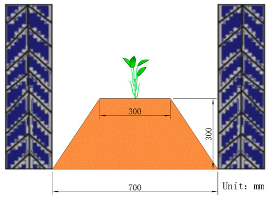
Figure 1.
Single-ridge single-row cultivation model.
This model allows for the full mechanization of tillage, planting, management, and harvesting using a single tractor. It offers advantages such as high economic efficiency, simplicity in setup, broad adaptability, and low investment requirements, making it suitable for medium- and small-plot operations in most regions. In flat lowland areas, it can be paired with medium-sized four-wheeled tractors, while in hilly or small plots, walking tractors or mini tillers can be utilized. However, for larger fields, the machinery can be configured for multi-row operations to enhance efficiency.
2.2. Sweet Potato Seedling Transplanting Methods
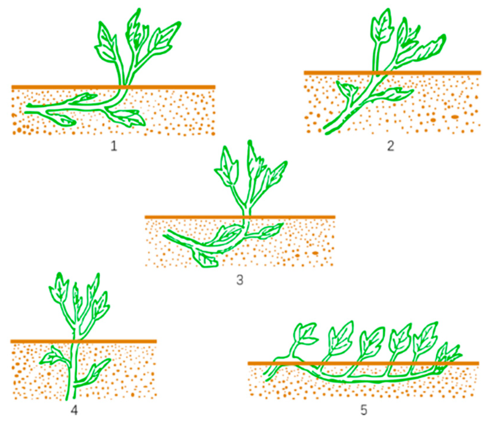
Due to the tuber formation characteristics of sweet potatoes, sweet potato seedlings cannot be transplanted in soil-covered plug trays like vegetables. Instead, they must undergo a seedling cultivation process followed by cutting and then bare-root transplantation. Sweet potato mainly has five traditional planting methods: horizontal planting, diagonal planting, boat-bottom shaped planting, straight planting, and vine-pressing planting [6], as shown in Figure 2. The horizontal planting method requires the seedling to be planted in the soil part of the horizontal posture in the basic conditions of the potato, where each section is mostly occupied by rooting potato, with a less empty section having more potatoes, potato size uniformity, and other advantages. The oblique planting method requires the seedling to be planted in the soil part of the vertical direction at a certain angle, where the number of single-plant potatoes compared with the horizontal planting method is less than the number of larger potatoes in the upper nodes, and the lower nodes have smaller potatoes or even no potatoes. The ship-bottom-shaped planting method requires the seedling to be planted in the soil part of the middle of the pressure, where the head and tail ends of the two thus resemble the bottom of a ship. The seedling is implanted into the soil section more, causing more nodes to be close to the soil surface, which is conducive to the potatoes and leads to higher yields; however, at the central part of the seedling in the soil, the deeper nodes tend to be small and have fewer potatoes, or they can even become empty nodes. The direct planting method requires that the seedling be inserted directly into the soil. Due to the deeper direct insertion into the soil, only a few nodes are distributed in the topsoil layer of the potato species; the general number of single-plant potatoes is small; the potato has more than a few kinds of nodes in the upper part of the plant; expansion is fast; and the rate of large potatoes is high. The pressure vine planting method requires the top of the potato seedlings to be buried in the soil at both ends. The leaves are all exposed to the ground and results in more potatoes that are large; the stems and leaves are not easy to grow. It has high yield advantages, but poor drought resistance, and requires more planting labor with only a small area of high-yield cultivation.
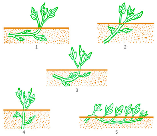
Figure 2.
Five traditional methods of planting sweet potato: 1. horizontal planting; 2. inclined planting; 3. boat-shaped planting; 4. vertical planting; and 5. layering planting.
A comparative analysis of these five different planting methods, in conjunction with high-yield cultivation techniques, indicates that the current predominant practices involve horizontal, inclined, and vertical planting methods. Horizontal and inclined planting methods are primarily suitable for fresh sweet potato seedlings, while vertical planting is mainly used for waxy sweet potato seedlings. Horizontal planting has advantages over inclined planting, including higher tuber yield, uniformity in tuber size, better marketability, and an overall higher productivity, making it the leading method for fresh sweet potato seedling transplantation. For horizontal planting, the seedling length should be approximately 30 cm, with a horizontal planting depth of about 15 cm and a planting depth of 5~8 cm.
3. Design of the Sweet Potato Seedling Belt with Compound Transplanter
3.1. General Structure of the Machine
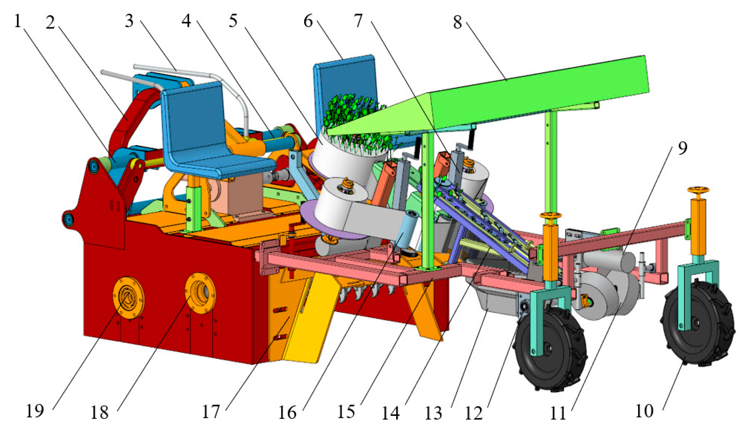
The overall structure of the sweet potato seedling belt with compound transplanter is schematically shown in Figure 3, which mainly consists of key components such as sliding rail, suspension device, hydraulic oil pipe, hydraulic cylinder, seedling roll belt, seat, angle adjustment, seedling tray, motor, support wheel, suppression wheel, mulching screw, furrow opener, seedling conveyor belt, frame, tension roller, monopoly shaping plate, soil crushing roller, rotary tillage cutter shaft and so on.

Figure 3.
Structural diagram of the sweet potato seedling belt with compound transplanter: 1. sliding rail; 2. suspension device; 3. hydraulic oil pipe; 4. hydraulic cylinder; 5. seedling roll belt; 6. seat; 7. angle adjustment; 8. seedling tray; 9. motor; 10. support wheel; 11. suppression wheel; 12. mulching screw; 13. furrow opener; 14. seedling conveyor belt; 15. frame; 16. tension roller; 17. monopoly shaping plate; 18. soil crushing roller; and 19. rotary tillage cutter shaft.
3.2. Working Principle
During operation, the machine is connected to the rear of a tractor via a three-point hitch and coupled to the tractor’s power output shaft using a universal joint. The rotary tillage part cuts and pulverizes the soil and throws it to the crusher rollers, which further crush the soil before the ridge shaping plate shapes it, completing the ridge-making operation. Manually, the rolled seedling belt is loaded onto the carrying device, and the dual-layer seedling belt is initially separated and bonded to the separation roller. A motor drives the separation roller to separate and collect the seedling belt. Once separated, the seedlings belt enters a conveyor belt driven by a motor, which transports the seedlings diagonally downward into the prepared seedling ditch. Once the roots touch the bottom of the ditch, the seedlings continuously bend and take a horizontal position. After the seedlings detach from the conveyor belt, the soil covering device performs soil covering and exposes the seedling tips to complete the seedling transplantation. Simultaneously, the bidirectional offset mechanism can be adjusted, allowing the equipment to operate along the edges of the field, between ridges, and in “S”-shaped operations.
3.3. Main Technical Parameters
According to the appropriate mechanization mode of operation and sweet potato horizontal planting agronomic requirements in sweet potato production, the design of the transplanting machine needs to meet the operation requirements of a ridge height of 300 mm and a distance between the center of the two ridges (ridge spacing) of 900 mm. According to the requirements of the planting of fresh potatoes, a planting spacing of 200~300 mm, a planting depth of 50~80 mm, and a planting spacing qualification rate of ≥90% are needed. In order to adapt to small-field operations, the machine needs to be compact and have low power consumption. The main technical parameters of sweet potato seedling with the compound transplanter are shown in Table 1.

Table 1.
Main parameters of sweet potato seedling with compound transplanter.
4. Design of Key Component Parameters
4.1. Design of Key Parameters for Seedling Belt Carrying Device
4.1.1. Design of Seedling Belt Loading Program
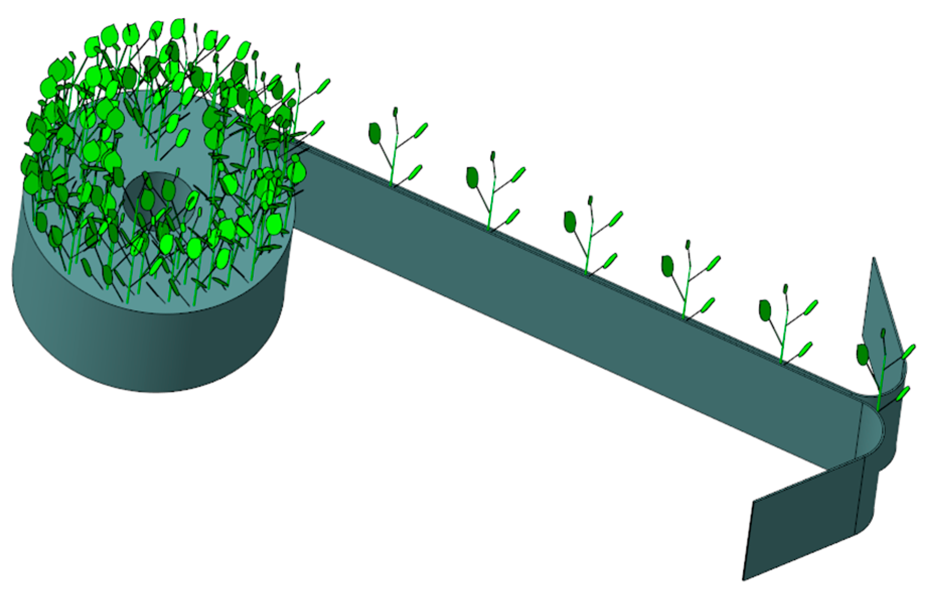
Currently, sweet potato seedling transplanting machines primarily operate as semi-automatic systems with manual seedling feeding. The single-row operational efficiency of the equipment is limited by the manual feeding efficiency, resulting in relatively low overall productivity. Without improvements in feeding efficiency, significant enhancements in the machine’s single-row operation efficiency are unlikely. To address these challenges, this section focuses on improving seedling feeding efficiency by innovatively proposing a seedling belt feeding technology solution. This approach constrains irregular and unordered sweet potato seedlings to the seedling belt in a standardized, orderly manner, allowing for specification and organization of the seedlings. The feeding method transitions from individual manual feeding to feeding entire rolls of the seedling belt. These seedling belt carrying devices can accommodate 50, 100, 200, or more seedlings as needed, leading to substantial improvements in feeding efficiency. Based on the previously measured geometric parameters and mechanical characteristics of sweet potato seedling plants, the seedling belt design was developed, as illustrated in Figure 4.
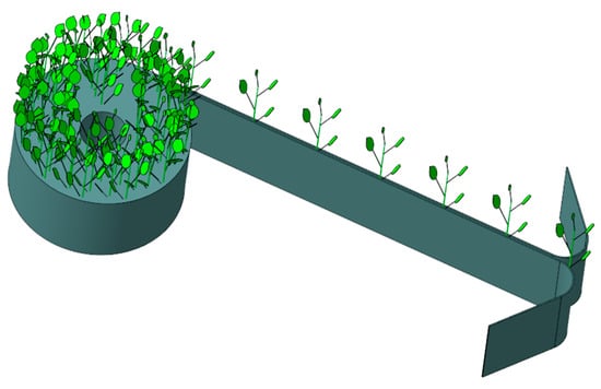
Figure 4.
Design of the sweet potato seedling belt carrying device.
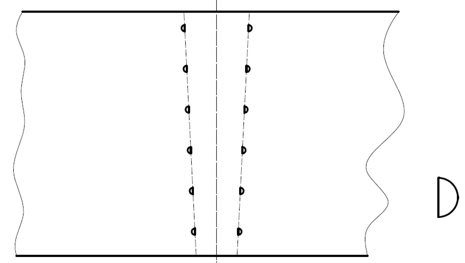
The designed seedling belt carrying device consists of two layers with a width of 150 mm, featuring designated planting positions at specified intervals. To facilitate manual planting, the upper openings of these positions have a width of 40 mm, while the lower openings measure 20 mm. The seedlings are placed from the upper opening to the lower opening, with roots positioned at the bottom of the lower opening, ensuring a spacing of 200 mm between seedlings. The preliminary selection of the seedling belt’s materials includes paper-based and polymer-based dual-layer belts. The bonding methods for the seedlings belts can be continuous, intermittent, or dot-style. Experimental research has shown that under the same temperature, pressure, and sealing time conditions, the dot-style structure is easier to separate. Therefore, the bonding points of the seedling belt are designed as semicircular structures, with bonding methods chosen based on the materials used—either adhesive or point-sealing techniques. In conclusion, the differing sizes of the upper and lower openings and the semicircular design of the bonding points facilitate manual seedling placement. Additionally, the dual-layer seedling belt requires only minimal separation force during detachment. The specific structural design of the seedling belt carrying device is shown in Figure 5.
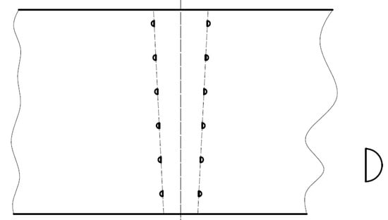
Figure 5.
Structural configuration of the sweet potato seedling belt carrying device.
4.1.2. Experimental Research on Seedling Belt Carrying Device
To verify the suitability of different materials for the seedling belt carrying device and to determine the optimal material, experiments were conducted on paper-based carrier belts and polymer-composite carrier belts for sweet potato seedlings.
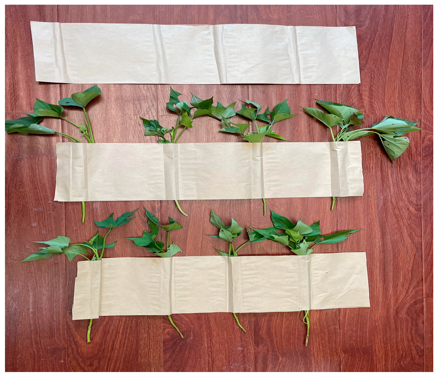
The paper-based carrier belt is constructed by bonding two layers of paper with adhesive, allowing for the manual insertion of the sweet potato seedlings into the designated slots of the belt. Experimental results indicate that sweet potato seedlings tend to lose moisture and wilt after a period when placed in the paper-based carrier belt. Additionally, the paper belt can easily break when exposed to water, making it unsuitable for watering or moisture-retaining operations, ultimately failing to maintain the freshness of the seedlings. Furthermore, the separation of the two layers of the paper carrier belt post-bonding is challenging, the bonding process is complex, and the cost of paper belts is relatively high, as shown in Figure 6.
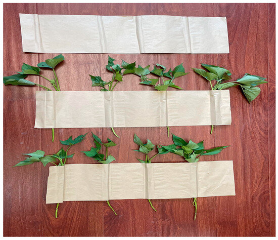
Figure 6.
Paper seedling carrier.
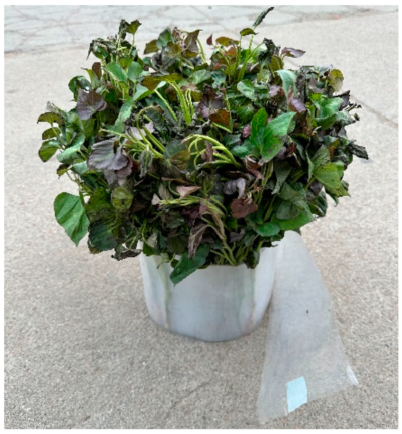
In contrast, the polymer-composite carrier belt is bonded using a thermal pressing technique to secure the two layers at specified points and distances. This method also allows for the manual insertion of the seedlings into the carrier belt’s designated slots before rolling into rolls of polymer-composite carrier belts. To ensure the vitality of the seedlings, these polymer-composite rolls can be placed in a water tray or nutrient solution; however, care must be taken not to submerge them for too long, as prolonged exposure can lead to root bending, negatively affecting the subsequent growth of the tubers. Experimental findings demonstrate that the polymer-composite belts exhibit high strength, excellent flexibility, and low cost. When planting at a density of 3000~4000 seedlings per acre, the cost of the carrier belt is estimated to be between 40 and 50 RMB per acre, which aligns well with user production requirements. Consequently, polymer-composite carrier belts are preferred, as illustrated in Figure 7.
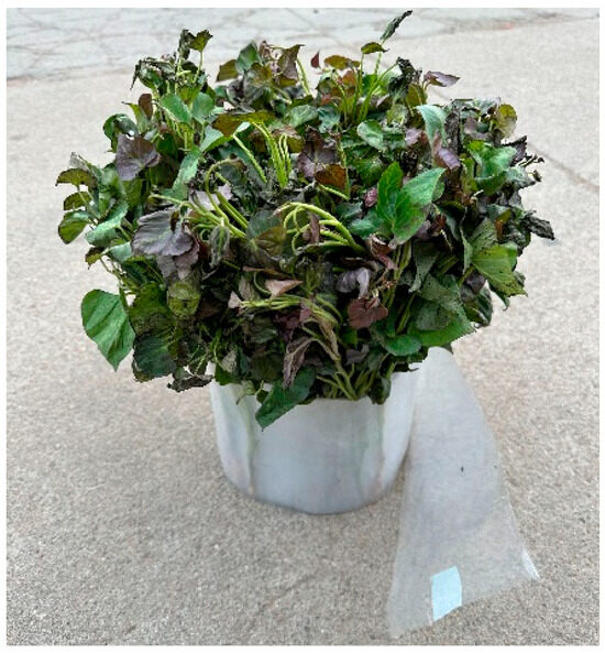
Figure 7.
Polymer seedling carrier.
4.2. Design of Key Parameters for Offset Tillage and Ridge Formation
4.2.1. Design of the Bidirectional Offset Device
To address issues such as the mismatched wheel spacing of tractors, incomplete coverage in hilly or small plots, and difficulties in switching rows during ridge cultivation operations [7], a hydraulic bidirectional offset mechanism has been designed. This mechanism allows the equipment to operate close to field edges and rows, as well as execute “S”-shaped movements. Furthermore, it enables the equipment to align with the ridge edges during the end-of-row operations, minimizing the distance between neighboring ridges, improving equipment adaptability, and enhancing plot utilization.
The hydraulic bidirectional offset mechanism derives its power from the tractor. During operation, a hydraulic oil line connects to the tractor’s hydraulic interface. Depending on the specific offset operation required, a manual directional valve controls the flow of hydraulic oil in and out of the left and right hydraulic cylinders, enabling lateral movement of the hydraulic rod, which is connected to the frame. This configuration allows the bidirectional offset mechanism to pivot around the three-point hitch to achieve lateral offset, as depicted in the schematic in Figure 8.
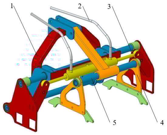
Figure 8.
Structural diagram of the bidirectional offset mechanism: 1. linking device; 2. hydraulic oil hose; 3. hydraulic cylinder; 4. slide guide; and 5. connection plate.
Based on the parameters of tractors with power ratings between 50 and 70 horsepower, the left and right offset length of the mechanism is set at 20 cm, facilitating edge and aligned operations [8]. The hydraulic cylinder’s body length is approximately 60 cm, while the stroke of the single-sided hydraulic rod is 20 cm. The load capacity of the hydraulic cylinder mainly arises from the sliding friction between the unit during translational movement and the frame. Based on trials of the initial prototype, the equipment weight is around 320 kg, translating to a gravitational force of approximately 3200 N. The installation position of the bidirectional offset mechanism is centrally located within the width of the three-point hitch with no imbalanced forces set for operation. The load force can be calculated using the following formula:
In the formula, F is load force, N; is the coefficient of sliding friction; and is the weight of the individual unit, N.
According to the Mechanical Design Handbook, the inner diameter of a hydraulic cylinder can be calculated using the following formula:
In the formula, —inner diameter, m; —rod diameter, m; and —actual load pressure, Mpa.
During actual operation, when the coefficient of sliding friction is 0.1, the rated output pressure of a hydraulic system on a 50~70 horsepower tractor is 16 MPa. Based on the Mechanical Design Handbook, if the gear ratio is taken as 1.46, can be determined using the following formula:
From this, Formula (3) can be expressed as follows:
By solving Equation (4), the result is calculated to be 6.09 mm. This indicates that a hydraulic cylinder inner diameter of 6.09 mm is sufficient to meet the operational requirements for bidirectional offset. Based on commonly used hydraulic cylinder specifications, a double-rod hydraulic cylinder with equal speed and stroke is selected. The main working parameters of the hydraulic cylinder are shown in Table 2.
Table 2.
Hydraulic cylinder working parameters.
4.2.2. Design of the Precision Tillage Device
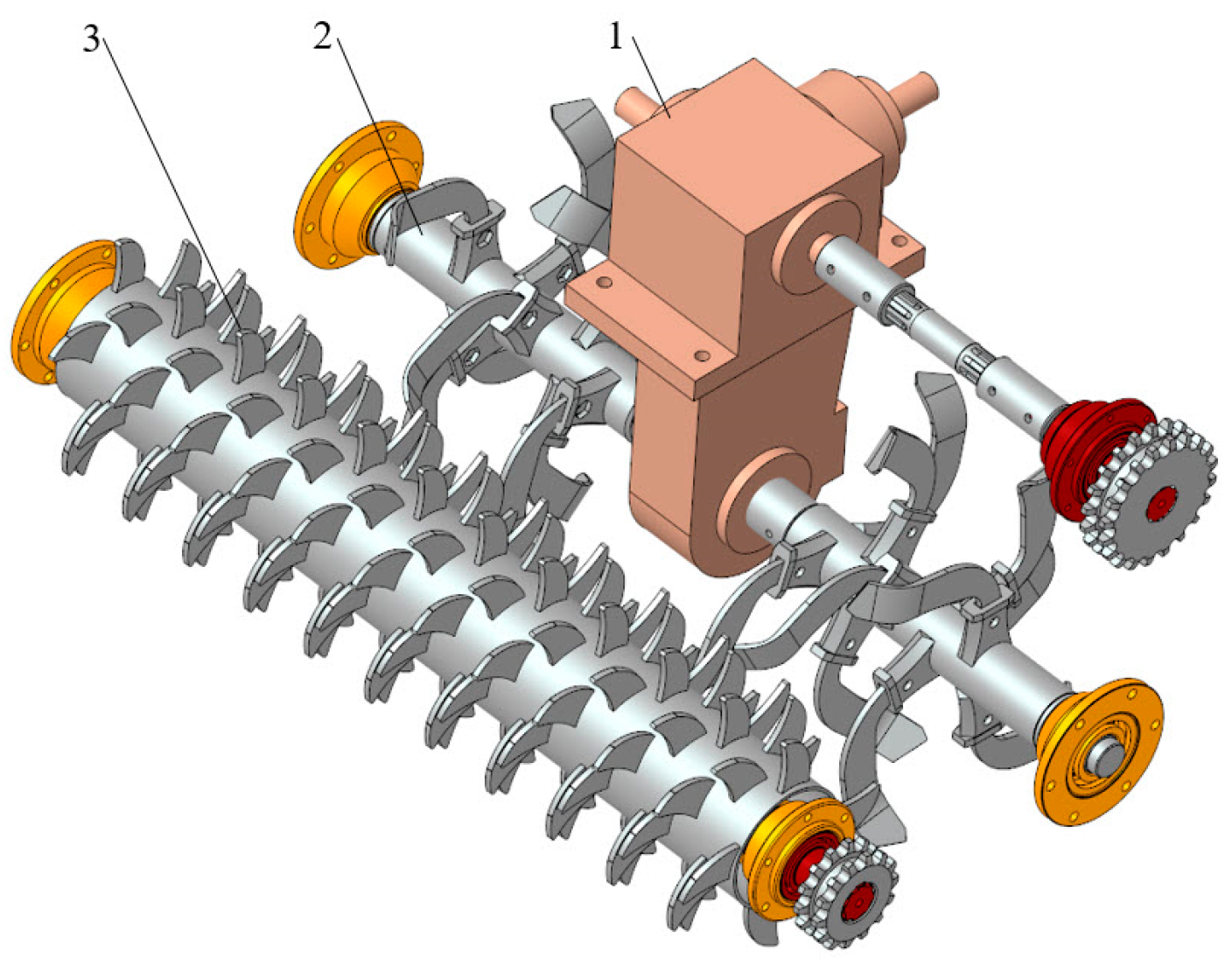
Soil fragmentation is a critical factor affecting the quality of ridge shaping and transplanting [9,10]. To enhance soil fragmentation and improve the quality of ridge shaping and transplanting, this study utilizes a dual-structured “rotary tillage + soil crushing“ precision tillage device. The dual-rotation mechanism is also effective in minimizing the effect of root stubble in the soil on the quality of starting and transplanting, as demonstrated in Figure 9.

Figure 9.
Structural schematic of the precision tillage device: 1. gearbox; 2. rotary tillage device; 3. soil crushing device.
The power for the fine tillage device is provided by the tractor, with a universal joint connecting the tractor’s rear power output shaft to the gearbox of the rotary tiller. The gearbox, through gear transmission, supplies power to the rotary tillage device, while the side axle of the gearbox provides power to the soil crushing mechanism. During operation, the rotary tillage device throws the soil and root residues into the crushing device, where the soil clumps and residues are further cut into finer pieces. To optimize the soil crushing rate, the crushing blades of the device are arranged in an interleaved spiral configuration. Based on the preliminary transplanting test results, the lateral spacing for the crushing blades is designed to be 30 mm, satisfying the demands of the transplanting operations.
4.2.3. Design of the Ridge Shaping Device
The ridge shaping device primarily consists of a ridge shaping plate and an adjustment mechanism, as shown in Figure 10.
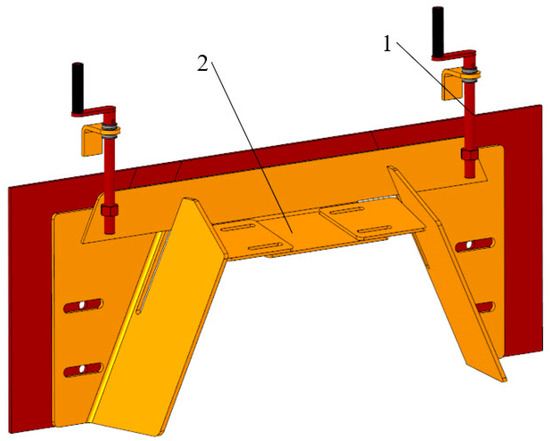
Figure 10.
Structural diagram of the ridge shaping device: 1. ridge shaping plate and 2. adjustment mechanism.
To ensure soil permeability and ridge compaction, the formation plate is designed with a “trumpet” shape, with dimensions configured according to mechanized operational modes. The entrance of the ridge shaping plate is designed for a ridge height of 350 mm, a bottom width of 800 mm, and a top width of 350 mm, while the exit plate is designed for a ridge height of 300 mm, a bottom width of 700 mm, and a top width of 300 mm. Furthermore, to enhance the adaptability of the equipment, the ridge shaping plate can be adjusted laterally, and its height can be modulated via an adjustment lever.
4.3. Design of Key Parameters for Seedling Separation
4.3.1. Design of the Seedling Separation System
The seedling separation process refers to the stable separation and recovery of the double-layer seedling belt, allowing the sweet potato seedlings to be extracted from the roll and transferred in a single, orderly manner to the seedling transport belt. The key components of the seedling separation apparatus mainly include the active separation mechanism, the seedling holding mechanism, and the seedling belt tensioning mechanism, as shown in Figure 11.
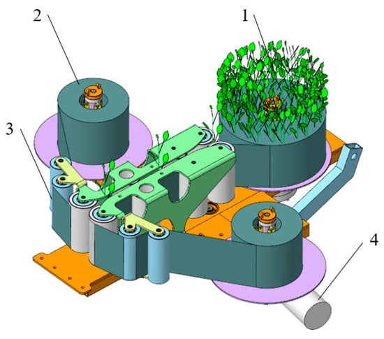
Figure 11.
Structural diagram of the seedling separation device: 1. sweet potato seedling belt; 2. seedling separation device; 3. tensioning device; and 4. drive motor.
During operation, a motor drives the separation mechanism to perform a rotational motion. Through this rotational movement, the double-layer seedling belt is separated and collected into a roll. The seedling holding mechanism rotates around the axis of rotation to facilitate the seedling separation operation. To ensure an orderly and precise transfer of the separated seed potatoes to the transport device, it is essential to maintain continuous tension in the seedling belt throughout the process. This requires that both the active separation mechanism and the seedling holding mechanism rotate without self-rotation during their movements under the tensioning condition. Additionally, to enable the rapid loading and unloading of the rolled seedling belt and facilitate the quick detachment of the collected rolls by the separation mechanism, research on rapid replacement devices needs to be conducted.
4.3.2. Design and Selection of the Constant Tension Device
Seedling separation refers to the process of stably separating and recovering the double-layered seedling belt, allowing the sweet potato seedlings to be extracted from the carrier and conveyed individually and orderly onto the seedling delivery belt.
The seedling carrying mechanism produces a rotational motion under the influence of the separation mechanism. In the absence of a damping device, the rotational axis may easily self-rotate due to inertia, preventing the seedling belt from remaining in a tensioned state. To eliminate this issue and ensure that the seedling belt maintains constant tension during the separation process, a magnetic particle brake is designed, as illustrated in Figure 12.

Figure 12.
Magnetic particle brake.
The magnetic particle brake utilizes a magnetic particle clutch, which transmits torque using magnetic particle clutches under the effect of electromagnetic force. When current flows through the coil, a magnetic field is generated, magnetizing the internal powder and causing it to attract itself, forming a strong magnetic coupling surface. As the current increases, the powder is activated in the magnetic field, which increases the friction of the clutch and enhances torque transmission between the input and output shafts. Conversely, when the current decreases or is cut off, the magnetization of the powder decreases, reducing the coupling force and thereby decreasing or disconnecting torque transmission. Therefore, by adjusting the current intensity, one can accurately control the friction and torque output of the clutch, enabling adjustments to the tension or rotational speed.
The constant tension is related to the characteristics of the seedling belt material, calculated using a specific formula:
In the formula, is the tension coefficient; is the yield strength, MPa; is the width of the seedling carrier, mm; and h is the thickness of the seedling carrier, mm. Here, < 1; when = 1, the tension in the carrier reaches the yield limit. After field adjustments, is set to 0.4; = 21 MPa = 21 N·mm−2; = 150 mm, = 0.07 mm, leading to a calculated constant tension = 88 N.
According to the definition of torque, the maximum torque for the film unwind roll can be calculated using the following formula:
In the formula, is the torque of the film unwind roll, N·m; is the tension in the seedling carrier, N; and is the diameter of the film unwind roll, m. With the maximum seedling carrier roll diameter being 0.5 m, the calculated maximum torque for the film unwind roll is 22 N·m. Therefore, when selecting a dual-shaft magnetic particle clutch, its rated torque must not be less than 22 N·m. The FL-25-S dual-shaft magnetic particle clutch is selected, with its performance parameters listed in Table 3 below.
Table 3.
Magnetic particle clutch performance parameters.
This paper selects the FL-25-S dual-shaft magnetic particle clutches, which allows adjustable torque ranging from 0 to 25 N·m and a rotational speed of 0~1400 rpm, meeting the requirements for maintaining constant tension in the seedling belt during roll operations.
Experimental studies indicate that the electromagnetic damping device maintains stable tension during the rotation of the seedling belt, keeping it in a tensioned state. The damping device ensures constant tension, which can also be adjusted based on need, possessing advantages of convenience, stability, and reliability.
4.3.3. Design of the Quick-Change Device
Through research, it has been found that the core shaft of the seedling roll production companies is commonly a cylindrical shape with a certain wall thickness, in accordance with relevant standards. The square coordinate fit for the core shaft is relatively rare. When using a cylindrical core shaft, a hinged quick replacement device has been designed to achieve the rapid switching of the rolled seedling belt and separation mechanism after coiling, while also preventing the rolling of the seedling belt and the coiled collection belt, as shown in Figure 13.
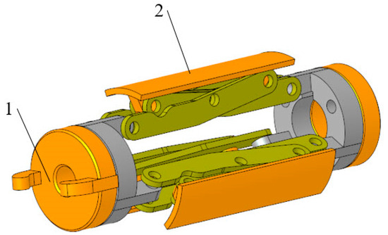
Figure 13.
Structural diagram of the quick-change device: 1. locking mechanism and 2. support device.
The inner diameter of the seedling core shaft is 60 mm, and to standardize dimensions, the inner diameter of the collection belt shaft is also set to 60 mm. The design of the quick replacement device allows for a contraction and expansion range of 59~61 mm. During operation, the cylindrical core shaft is fitted into the replacement device, and by rotating the adjustment mechanism, the hinged structure is raised to facilitate quick replacement, which also prevents self-rotation. Conversely, the hinged structure can be contracted for rapid disassembly.
4.4. Design of Key Parameters for Horizontal Positioning and Shaping
4.4.1. Principle of Horizontal Positioning and Shaping
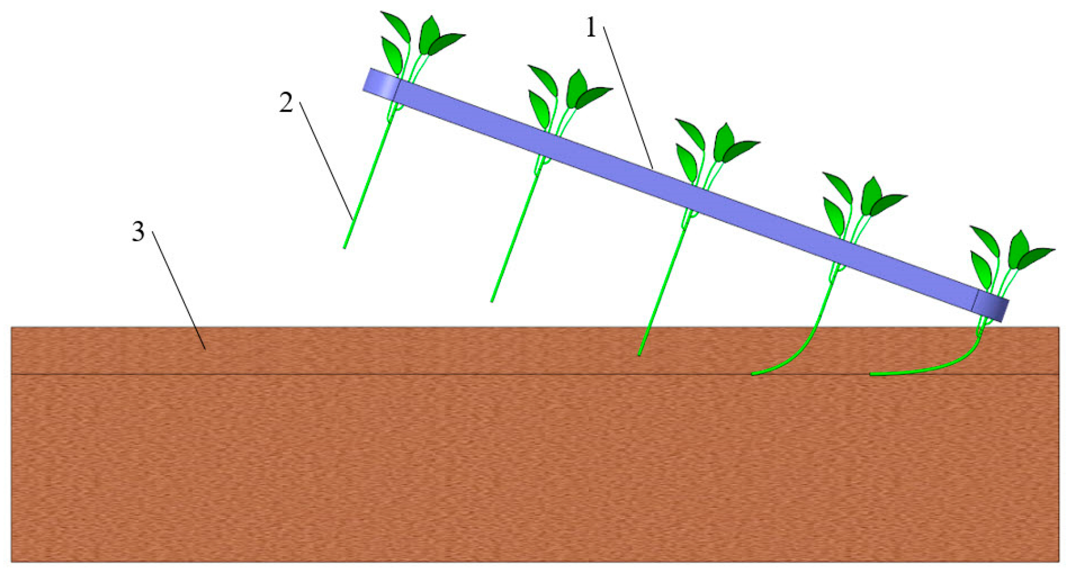
The process of achieving a horizontal posture of the seedlings refers to the horizontal positioning of the portion of the seed potatoes that is planted in the soil, as illustrated in Figure 14. During this horizontal positioning process, it is crucial to avoid damage to the seedling caused by the gripping components, as well as to prevent bending damage to the seedling roots when they touch the ground. To minimize gripping damage to the seedlings, the gripping component employs a flexible design made with double-layer sponge belts. Based on the previous experiments on seedling bending, it was determined that when the bending angle of the seedlings exceeds 90 degrees, bending damage is likely to occur. To avoid this, after achieving a horizontal posture, it is optimal for the angle between the seedling tip and the horizontal direction to be around 80 degrees. Furthermore, considering the physical characteristics of the seedlings, the width of the gripping component should not be excessively wide, as a wider grip may lead to the phenomenon where the stem separates from the transport belt while the leaf petiole and leaves remain attached. Through experimental research on different widths of the seedling belt, a width of 30 mm has been determined as suitable.
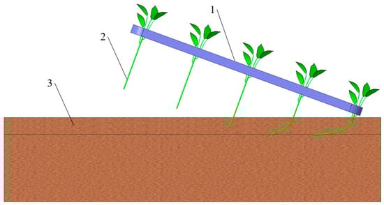
Figure 14.
Schematic diagram of horizontal positioning and shaping: 1. seedling delivery belt; 2. sweet potato seedlings; and 3. ridge body.
After the seedlings are separated from the seedling belt, they are conveyed downward at an angle by the grabbing component until the seedling roots touch the ground and bend to meet the horizontal planting requirement. To ensure a smooth transition of the seedlings onto the transport belt, the transport belt must simultaneously grip the seedlings before separation. Additionally, during the angled downward transportation of the seedlings, to guarantee the stability of the gripping posture and prevent the seedlings from falling during transport, an elastic pressing device should be added to the inner side of the transport belt to maintain stable gripping on the seedlings.
4.4.2. Motion Analysis for Horizontal Positioning and Shaping
The movement relationships during the downward transportation of the seedlings on the transport belt are illustrated in Figure 15.
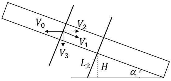
Figure 15.
Motion analysis diagram for horizontal positioning and shaping.
In the figure, represents the forward speed of the machinery, is the speed of the transport belt, is the horizontal component speed of the transport belt, and is the vertical component speed of the transport belt. The length from the seedling root to the edge of the transport belt is , and the distance from the edge of the transport belt to the bottom of the ditch is . Once the machinery is operating stably, for the seedlings to achieve a horizontal posture when the roots touch the ground, the seedlings must exhibit a tendency to move in the opposite direction of the machinery’s forward motion. The following conditions must be met:
If the specified planting distance for the seedlings is , and the spacing between seedlings on the belt is , the time required to plant the next seedling after the previous one is . The transplanting machine must maintain stable planting spacing throughout the process, then
is the vertical speed of the transport belt, then
Substituting Equation (9) into (8) yields
Based on the characteristics of horizontal posture formation, the planting distance can be expressed as
After simplification,
When the seedlings separate from the transport belt, the conditions to achieve a horizontal posture must also be satisfied:
That is,
After simplification,
In summary, the angle between the transport belt and the horizontal is ; this paper designates the angle between the transport belt and the horizontal to be .
4.5. Design of Key Parameters for Planting Upright Seedlings
4.5.1. Design of the Ditching and Depth-Fixing Part
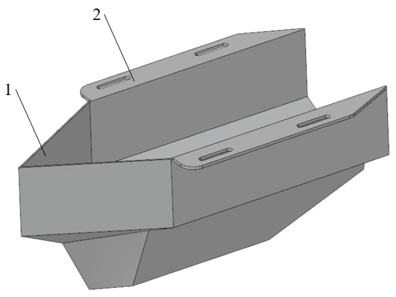
The main function of the grooving and depth setting parts is to open the seedling groove to prepare for the potato seedling to land on the bed, mainly including the grooving piece, connecting plate, etc. According to the potato seedling and seedling conveyor belt, the groove opener is designed as a large upper and small lower structure, as shown in Figure 16. The ditching and depth-fixing part is firmly attached to the frame through connecting plates. According to the agronomic requirements for sweet potato seedling planting, the ditch depth is designed to be 80 mm, with an adjustable ditch depth range of 0~80 mm. According to the physical characteristics of the potato seedlings, in order to minimize the collision of the seedlings with the side wall of the groove opener when they are transported diagonally downward, the width of the groove is designed to be 50 mm. To allow the seedling transport component to be submerged into the ditch opener, the upper opening of the ditch device is designed to be 190 mm wide. In order to make the trenching and depth setting parts have better soil breaking performance, after trenching to form a “clean zone” inside the trenching and depth setting parts, the design of the two trenching pieces into the soil at an angle of 35° can effectively reduce the impact of the soil, weeds, etc., on the transplanting [11,12,13], and the position of its position before and after is adjustable, with an adjustable range of 0~50 mm.
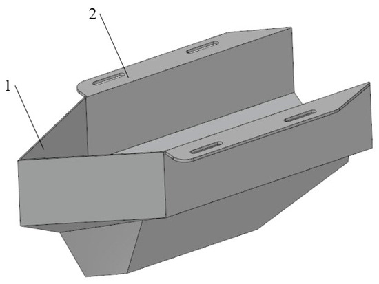
Figure 16.
Structural diagram of the ditching and depth-fixing mechanism: 1. opening blade and 2. connection plate.
4.5.2. Design of Key Parameters for Soil Covering and Exposing Seedling Tips
Once the seedlings have achieved a horizontal posture and are about to be released from the seedling transport belt, soil covering of the seedling roots is required while ensuring that the seedling tips remain exposed above the soil surface, referred to as the “soil covering and exposing seedling tips”. To achieve this operation, an active screw soil covering and tip exposure mechanism has been designed.
The active screw soil covering and exposing seedling tip mechanism mainly consists of a driving motor, connecting plate, screw mechanism, transmission shaft, chain case, and position adjustment plate, as shown in Figure 17. The motor drives the screw mechanism to perform the soil covering and exposes the seedling tips via chain transmission. The position of the screw mechanism can be adjusted both vertically and horizontally using the adjustment plate.
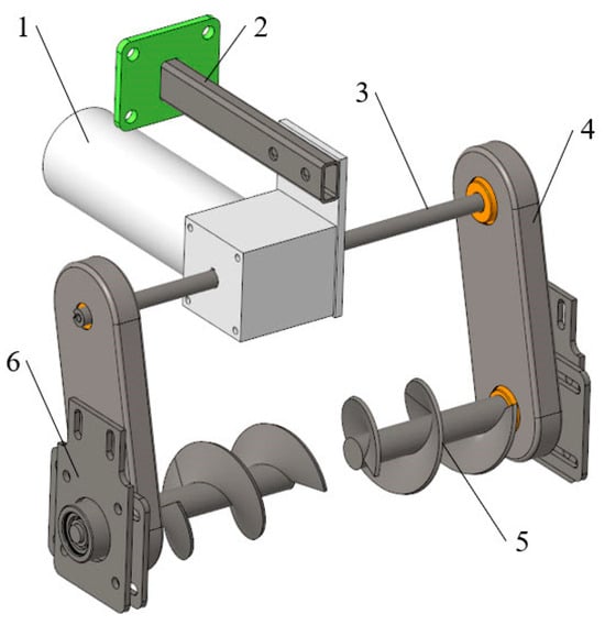
Figure 17.
Active spiral soil covering and exposing seedling tip components: 1. drive motor; 2. connection plate; 3. drive shaft; 4. chain cover; 5. spiral mechanism; and 6. position adjustment plate.
Parameter Design of the Screw Mechanism
The soil covering process requires soil particles to move outward along the axial direction, meaning that the velocity vector of the particles must move from the inside toward the outside (with a friction angle relative to the normal of the screw surface) [14,15,16,17]. The conditions for this are as follows:
In the formula, is the screw angle (°) and is the friction angle between the soil and the steel plate (°). Since the screw angle varies at different points along the blade, with the maximum screw angle at the minimum radius, it is sufficient for the screw angle at the inner diameter to meet the conditions.
The theoretical volume of soil moved by the screw mechanism in the ditch can be considered as the volume of the furrow created, which can be modeled as a rectangular prism. The volume of soil required to cover the ditch can be expressed as
where is the working width (m); is the forward speed (m·s−1); and is the tillage depth (m). Based on the agronomic requirements for the sweet potato seedling transplanter and to improve transplanting efficiency, the operational speed of the tractor is set to be between 0.1 and 0.4 m·s−1. With a ditch width of 50 mm and a ditch depth of 80 mm, the volume of soil required to cover the ditch is calculated to be approximately 4 × 10⁻⁴~1.6 × 10⁻³ m3·s−1.
Referencing the design methods for open screw conveyors, to ensure stable soil movement and prevent clogging, the screw covering mechanism must meet the following requirements:
The conveying capacity of the screw mechanism must exceed the soil input rate, or sludging may occur.
The soil must not exhibit vertical jumping or rolling perpendicular to the direction of conveyance.
The soil must be conveyed axially, meaning that both axial forces and axial velocity must be greater than 0.
Based on the design principles of screw conveyors, the formulas for the design parameters of the screw mechanism are as follows:
Spiral outer diameter:
Shaft diameter:
Spiral speed:
Screw pitch:
In the formula, is the amount of mud transported, m3·s−1; is the comprehensive characteristic coefficient of the mud; is the filling coefficient; is the slope coefficient; is the bulk density of the conveyed material, t·m−3; and is the comprehensive characteristic coefficient of the material.
Since the left and right soil covering screws are arranged symmetrically, the mud transport capacity of each screw mechanism should be half of the total soil required to fill the seedling ditch, and thus is set to range between 2 × 10⁻⁴ and 0.8 × 10⁻³ m3·s−1. The topsoil for sweet potato seedling transplanting has a certain fluidity, referring to the design standards for screw conveyors, and the estimated comprehensive characteristic coefficient for the soil is taken as 0.0415. The filling factor is set to 0.4; since the spirals are positioned horizontally, the inclination coefficient is set to 1.0; the comprehensive characteristic coefficient for the soil is taken as 75; and the bulk density of the soil is set at 1.8 t·m−3.
From Equation (19), the outer diameter of the screw is calculated to be mm. Considering the overall mass of the machine and its compatibility with the tractor, the outer diameter is determined to be . From Equation (20), the screw shaft diameter is determined to be between 20 and 35 mm. To minimize the entanglement of grass on the shaft and to enhance soil transport capacity, the screw shaft diameter is chosen as mm. The pitch from Equation (22) is determined to be in the range of 50 to 220 mm. To ensure smooth soil transport within the screw and to prevent mud accumulation, the soil transport amount of each pitch section must exceed the combined mud input from the current and previous pitch sections. Therefore, this study adopts a variable-pitch, constant-diameter screw, where the pitch increases along the helices towards the furrow, with the largest pitch closest to the furrow. Based on the structure and configuration dimensions of the machine, the maximum operational rotational speed from Equation (21) is calculated to be 237 rpm.
5. Performance Testing and Analysis
To achieve efficient and sustainable sweet potato seedling planting, the performance of the sweet potato seedling belt transplanter is evaluated.
5.1. Testing Conditions and Equipment
In May 2023, a sweet potato seedling transplanting test was conducted in Qingzhou City, Shandong Province, where the test site was an idle winter field, consisting of sandy soil with a moisture content of approximately 16% to 18% (0~100 mm). The sweet potato seedlings used in the test were 300 to 350 mm in length and 4 to 6 in diameter. The test equipment primarily consisted of a Dongfanghong 504 tractor, sweet potato seedling belt transplanter, moisture meter, calculators, ruler, tape measure, tachometer, etc.
5.2. Experimental Design and Methods
To improve planting quality, achieve horizontal planting of the sweet potato seedlings, and enhance yield, quality, and uniformity of sweet potato seedling tubers, several key parameters affecting the whole machine’s performance and operational effectiveness were selected as test factors: the forward speed of the machine , the screw speed , and the spacing of the ribbons (the distance between the centerline of the screw shaft and the end of the conveyor belt, hereinafter referred to as the pitch of the screw belt). The planting spacing Z was taken as the evaluation index to characterize the operation quality of the machine. According to the above experimental plan, single-factor tests were conducted to identify the factors influencing the qualified rate of planting spacing and their respective ranges. A three-factor, three-level orthogonal test (L9(34)) [18,19] was designed, with factor levels shown in Table 4.
Table 4.
Factors and levels of the orthogonal test.
During the tests, different combinations of forward speed, spacing of the ribbons, and screw speeds were adjusted to calculate the qualified rate of planting spacing , thus analyzing and evaluating the operational performance of the machine. Each experimental group was repeated three times to take an average value [20]. The assessment criteria for the experiments were based on GB/T 5262 standards [21]. Three measurement areas were randomly selected within the test site, where each area must contain two adjacent operational widths. In each area, one row was chosen, and 120 consecutive planting spacings were measured [22]. A standard planting spacing of D = 200 mm was established, with measured spacings considered qualified if they fell within D(1 ± 10%). The percentage of qualified spacings relative to the total measured count was calculated to determine the qualified rate of spacings [23,24], based on Equations (23) and (24):
In the above formulas, the following notations are used:
—The number of qualified plant spacings in the testing area;
—Total number of samples determined in the detection area, = 120;
—The qualified rate of planting spacing in the detection area (%);
—The qualified rate of planting spacing (%);
—The number of detection areas, = 3.
5.3. Test Results and Analysis
The experimental results obtained from the orthogonal performance tests are presented in Table 5, where A, B and C represent the levels of the parameters , and , respectively.
Table 5.
Results and orthogonal test.
An analysis of the range values for each factor in Table 5 indicates that [25], regarding the evaluation indicators, the order of significance for each factor’s influence is as follows: , , with the optimal combination of factor levels identified as .
Using SPSS 21.0 data processing software, a variance analysis was performed on the experimental results, as shown in Table 6 [26]. As can be seen from Table 6, the value of the sum of squares of the error terms is much smaller than the sum of squares of the influencing factors, indicating that the interaction between the test factors does not have a significant effect on the test assessment indicators [27,28]. When analyzing the qualified rate of planting spacing , it is evident from the -value that the experimental factors and have a significant impact on the evaluation indicator . From , it is evident that the experimental factor has the greatest impact on the evaluation indicators, followed by factor , while factor has the least influence, which is consistent with the results of the range analysis.
Table 6.
Analysis of variance.
Combining the results of the range analysis and the variance analysis, it can be concluded that the best parameter combination for transplanting performance was , which corresponds to a forward speed of 0.3 m·s−1, a ribbon spacing of 60 mm, and a screw speed of 160 rpm.
5.4. Field Experiment
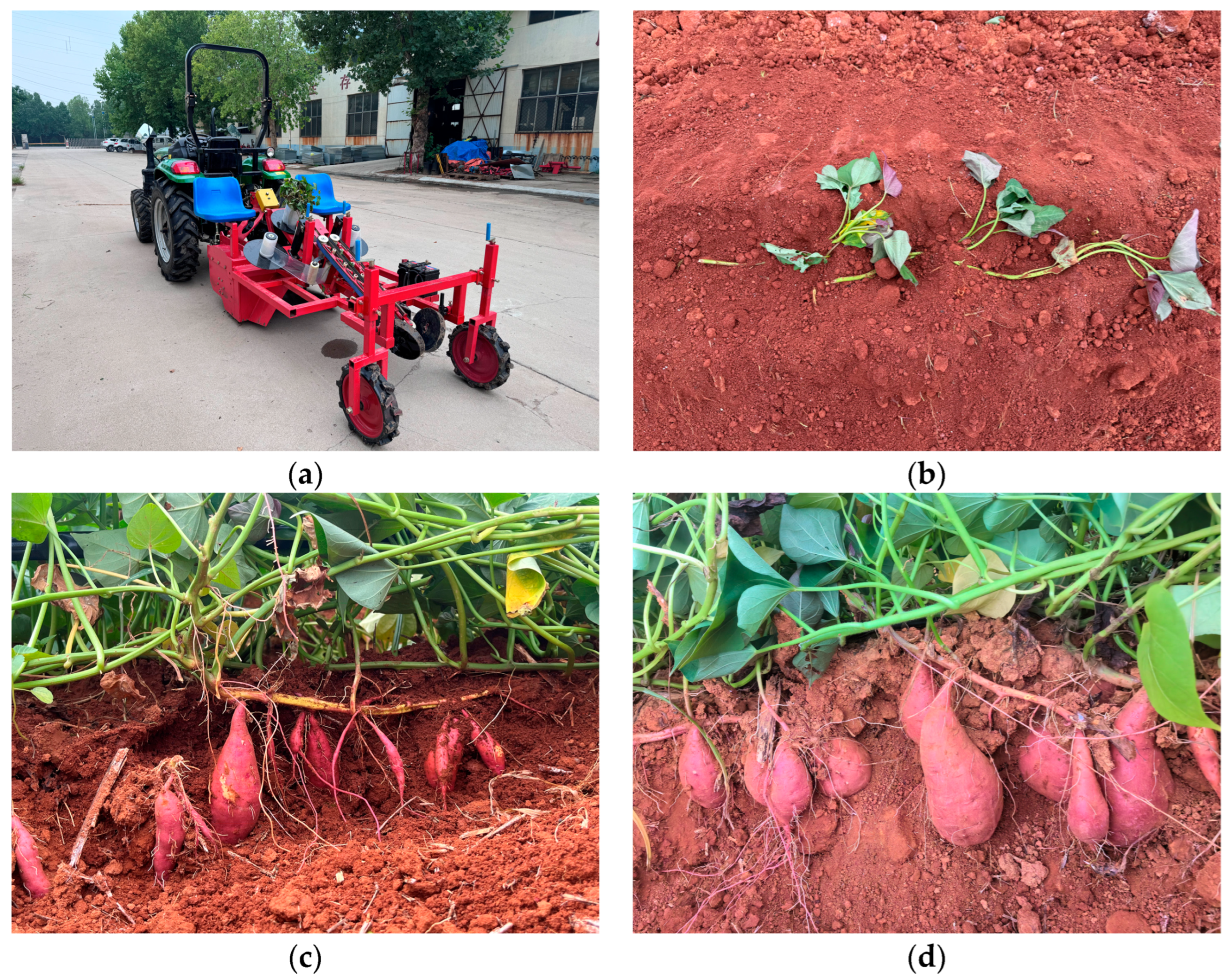
In order to verify the working performance of the transplanter in the above results, a field trial was conducted in May 2023 at the sweet potato planting base in Qingzhou City, Shandong Province, China. Prior to the experiments, the machine’s operational parameters were adjusted to the optimal combination: a forward speed of 0.3 m·s−1, a ribbon spacing of 60 mm, and a screw speed of 160 rpm. A total of six sets of repeated experiments were conducted, with each set containing 120 measured planting spacings. The results of these experiments are presented in Table 7 and in Figure 18.
Table 7.
Results of the field test.
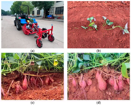
Figure 18.
Field experiment results: (a) field experiment equipment; (b) experiment result; (c) growth situation; and (d) growth situation.
The test results show that the average planting distance of the sweet potato bare seedling horizontal transplanter is 90.37%, which is in line with the relevant agricultural machinery industry technology and standards and local agronomic production requirements. The horizontal planting of potato seedlings can be realized, which is beneficial to improve the uniformity and yield of sweet potato.
6. Discussion
In this paper, the effects of machine advance speed, spacing between spirals and the screw speed on the planting spacing qualification rate were studied. Further optimization and improvement of the machine is needed in later experiments for indexes such as the planting depth qualification rate and planting spacing variation coefficient.
Additionally, it was observed during the experiments that, with the planting spacing fixed, there is a need to match the seedling delivery speed with the forward speed. However, as the roll diameter of the seedling conveyor increases, the relationship between the seedling separation line speed and the forward speed changes continuously, which affects the planting spacing to some extent.
The sweet potato seedling belt transplanter has preliminarily achieved automation in sweet potato seedling transplanting; however, manual intervention is still required to thread the seedlings onto the conveyor belt. Future research could focus on developing key technologies for automatic seedling bundling.
7. Conclusions
The designed sweet potato seedling belt replica transplanter initially realizes automatic and horizontal planting of sweet potato. The machine saves the labor of one to two people, and at an operating speed of 0.3 m·s−1, the machine plants 90 plants per minute, which improves the efficiency by more than 40% compared with the semi-automatic transplanting machine.
The main parameters affecting the working performance and operational effectiveness of the whole machine were obtained. Tests on the main parameters affecting the working performance and operational effectiveness of the whole machine were carried out. The test results show that the primary and secondary orders of the significance of the qualified rate of planting spacing for the impact evaluation index are , and , the optimal level combination of influencing factors is , the forward speed of the machine is 0.3 m·s−1, the spacing of the ribbons is 60 mm, and the screw speed is 160 rpm.
Transplanters meet sweet potato production requirements. The field test results show that under the optimal combination of factor levels, the -average rate of planting spacing was 90.37%, which met the relevant technical standards and agronomic requirements.
Author Contributions
Conceptualization, W.Y. and M.H.; methodology, W.Y.; software, K.L.; validation, W.Y., M.H. and C.W.; formal analysis, W.Y.; investigation, K.L.; resources, Y.J.; data curation, W.Y.; writing—original draft preparation, W.Y.; writing—review and editing, W.Y. and Z.R.; visualization, C.W.; supervision, Z.R.; project administration, W.Z. All authors have read and agreed to the published version of the manuscript.
Funding
This research was funded by the Key R&D Plan of Jiangsu Province (Grant No. BE2021311) and China Agriculture Research System of MOF and MARA (Grant No. CARS-10-B19).
Institutional Review Board Statement
Not applicable.
Data Availability Statement
The datasets used and/or analyzed during the current study are available from the corresponding author on reasonable request.
Conflicts of Interest
The authors declare no conflicts of interest.
References
- Li, Q.; Zhao, H.; Jin, Y.L.; Zhu, J.C.; Ma, D.F. Analysis and perspectives of sweetpotato industry contributing to national food security in China. Jiangsu JOAS 2022, 38, 1484–1491. [Google Scholar]
- Ma, D.F.; Li, Q.; Cao, Q.H.; Niu, F.X.; Xie, Y.P.; Tang, J.; Li, H.M. Development and prospect of sweetpotato industry and its technologies in China. Jiangsu JOAS 2012, 28, 969–973. [Google Scholar]
- Hu, L.L.; Ji, F.L.; Wang, B.; Ling, X.Y.; Hu, Z.C.; Yu, X.T. Latest developments of sweet potato mechanical transplanting in China. J. Chin. Agric. 2015, 36, 289–291, 317. [Google Scholar]
- Yan, W.; Zhang, W.Y.; Hu, M.J.; Ji, Y.; Li, K.; Qi, B. Present situation of research and expectation on plant mechanization of sweet potato in China and abroad. J. Chin. Agric. 2018, 39, 12–16. [Google Scholar]
- Sarkar, P.; Upadhyay, G.; Raheman, H. Active-passive and passive-passive configurations of combined tillage implements for improved tillage and tractive performance. Span. J. Agric. Res. 2021, 19, e02R01. [Google Scholar] [CrossRef]
- Ma, D.F.; Liu, Q.C.; Zhang, L.M. China Sweet Potato. Jiangsu PSTP 2021, 3, 337–340. [Google Scholar]
- Upadhyay, G.; Raheman, H. Performance of combined offset disc harrow (front active and rear passive set configuration) in soil bin. J. Terramech. 2018, 78, 27–37. [Google Scholar] [CrossRef]
- Zhang, L.M.; Ma, D.F. Main Cultivation Modes of Sweet Potato in China, 1st ed.; China Agricultural Science and Technology Press: Beijing, China, 2012; pp. 102–108. [Google Scholar]
- Zhao, H.; Liu, X.X.; Pan, Z.G.; Li, L.; Sun, Y. Agronomic characteristics and mechanized planting technology of sweet potato. J. Chin. Agric. 2021, 42, 21–26. [Google Scholar]
- Shao, Y.Y.; Xuan, G.T.; Hou, J.L.; Hu, Z.C.; Wang, Y.X.; Liu, Y. Design and Simulation of sweet potato mulched transplanting mechanism with “boat”-shape. ASABE 2018, 39, 2–6. [Google Scholar]
- Zhao, S.H.; Gu, Z.Y.; Yuan, Y.W.; Lu, J.Q. Bionic Design and Experiment of Potato Curved Surface Sowing Furrow Opener. Trans. CSAM 2021, 52, 32–42. [Google Scholar]
- Zhao, S.H.; Yang, L.L.; Zhang, X.; Hou, L.T.; Yuan, Y.W.; Yang, Y.Q. Design and Experiment of Zigzag Opener for Double-row No-tillage Seeding on Soybean Ridge. Trans. CSAM 2022, 53, 74–84. [Google Scholar]
- Zeng, S.; Tang, H.T.; Luo, X.W.; Ma, G.H.; Wang, Z.M.; Zang, Y.; Zhang, M.H. Design and experiment of precision rice hill-drop drilling machine for dry land with synchronous fertilizing. Trans. CSAE 2012, 28, 12–19. [Google Scholar]
- Qi, J.T.; Meng, H.W.; Kan, Z.; Li, C.S.; Li, Y.P. Analysis and test of feeding performance of dual-spiral cow feeding device based on EDEM. Trans. CSAE 2017, 33, 65–71. [Google Scholar]
- Yang, W.W.; Luo, X.W.; Wang, Z.M.; Zhang, M.H.; Zeng, S.; Zang, Y. Design and experiment of track filling assembly mounted on wheeled-tractor for paddy fields. Trans. CSAE 2016, 32, 26–31. [Google Scholar]
- Meng, H.W.; Gao, Z.J.; Kan, Z.; Lin, H. Design and experiment on dairy cow precision-feeding device based on equal-diameter and variable-pitch. Trans. CSAE 2011, 27, 103–107. [Google Scholar]
- Dai, F.; Zhang, S.L.; Song, X.F.; Zhao, W.Y.; Ma, H.J.; Zhang, F.W. Design and Test of Combined Operation Machine for Double Width Filming and Covering Soil on Double Ridges. Trans. CSAM 2020, 51, 108–117. [Google Scholar]
- Chen, K. Experimental Design and Analysis, 2nd ed.; Tsinghua University Press: Beijing, China, 2015; pp. 172–188. [Google Scholar]
- Shao, Y.Y.; Liu, Y.; Xuan, G.T.; Hu, Z.C.; Han, X.; Wang, Y.X.; Chen, B.; Wang, W.Y. Design and Test of Multifunctional Vegetable Transplanting Machine. IFAC 2019, 52, 92–97. [Google Scholar] [CrossRef]
- Shi, Y.Y.; Luo, W.W.; Hu, Z.C.; Wu, F.; Gu, F.W.; Chen, Y.Q. Design and Test of Equipment for Straw Crushing with Strip-laying and Seed-belt Classification with Cleaning under Full Straw Mulching. Trans. CSAM 2019, 50, 58–67. [Google Scholar]
- GB/T 5262; Measuring Methods for Agricultural Machinery Testing Conditions-General Rules. SAC: Beijing, China, 2008.
- Dai, F.; Zhao, W.Y.; Song, X.F.; Xin, S.L.; Liu, F.J.; Xin, B.B. Operating Parameter Optimization and Experiment of Device with Elevating and Covering Soil on Plastic-film. Trans. CSAM 2017, 48, 88–96. [Google Scholar]
- Yan, W.; Hu, Z.C.; Wu, N.; Xu, H.B.; You, Z.Y.; Zhou, X.X. Parameter optimization and experiment for plastic film transport mechanism of shovel screen type plastic film residue collector. Trans. CSAE 2017, 33, 17–24. [Google Scholar]
- Yan, W.; Hu, M.J.; Li, K.; Wang, J.; Zhang, W.Y. Design and experiment of horizontal transplanter for sweet potato seedlings. Agriculture 2022, 12, 675. [Google Scholar] [CrossRef]
- Hu, L.L.; Wang, B.; Wang, G.P.; Yu, Z.Y.; You, Z.Y.; Hu, Z.C.; Wang, B.K.; Gao, X.M. Design and experiment of type 2ZGF-2 duplex sweet potato transplanter. Trans. CSAE 2016, 32, 8–16. [Google Scholar]
- Xiang, W.; Wu, M.L.; Guan, C.Y.; Xu, Y.J. Design and experiment of planting hole forming device of crawler transplanter for rape (Brassica napus) seedlings. Trans. CSAE 2015, 31, 12–18. [Google Scholar]
- Xu, H.B.; Hu, Z.C.; Zhang, P.; Gu, F.W.; Song, W.L.; Wang, C.C. Optimization and Experiment of Straw Back-Throwing Device of No-Tillage Drill Using Multi-Objective QPSO Algorithm. Agriculture 2021, 11, 986. [Google Scholar] [CrossRef]
- Yang, H.G.; Yan, J.C.; Wei, H.; Wu, H.C.; Wang, S.Y.; Ji, L.L.; Xu, X.W.; Xie, H.X. Gradient Cleaning Method of Potato Based on Multi-Step Operation of Dry-Cleaning and Wet Cleaning. Agriculture 2021, 11, 1139. [Google Scholar] [CrossRef]


Disclaimer/Publisher’s Note: The statements, opinions and data contained in all publications are solely those of the individual author(s) and contributor(s) and not of MDPI and/or the editor(s). MDPI and/or the editor(s) disclaim responsibility for any injury to people or property resulting from any ideas, methods, instructions or products referred to in the content. |
© 2024 by the authors. Licensee MDPI, Basel, Switzerland. This article is an open access article distributed under the terms and conditions of the Creative Commons Attribution (CC BY) license (https://creativecommons.org/licenses/by/4.0/).