Article

Design and Testing of an Electric Side-Mounted Cabbage Harvester

1
School of Agricultural Engineering, Jiangsu University, Zhenjiang 212013, China
2
Key Laboratory of Modern Agricultural Equipment and Technology, Ministry of Education, Jiangsu University, Zhenjiang 212013, China
*
Author to whom correspondence should be addressed.
Agriculture 2024, 14(10), 1741; https://doi.org/10.3390/agriculture14101741
Submission received: 9 September 2024 / Revised: 29 September 2024 / Accepted: 30 September 2024 / Published: 2 October 2024
(This article belongs to the Section Agricultural Technology)

Abstract

:
To address the limitations of current cabbage harvesters in China, which are often designed for a single variety and lack adaptability to different cabbage varieties, we developed an electric side-mounted cabbage harvester suitable for field operations in the Jiangsu region of China. This design is informed by the statistical analysis of the physical and agronomic parameters of major cabbage varieties. The harvester consists of key components, including an extraction device, a leaf-stripping device, a clamping and conveying device, and a root-cutting device. Powered by a 120 Ah direct current (DC) power source, it is capable of performing cabbage extraction, feeding, clamping, conveying, root cutting, and boxing in a single operation for three hours. Through theoretical analysis of the key components, specific parameters were determined, and field tests were conducted to verify the design. The results of the field experiments indicate that all components of the cabbage harvester operated effectively. Optimal performance was observed when the extraction roller speed was set between 100 and 110 RPM, the conveyor belt speed at 60 RPM, and the cutter speed between 160 and 220 RPM, resulting in a low cabbage harvest loss rate. The harvest loss rates from the three experiments were 11.3%, 13.3%, and 12%, respectively, which meets the mechanical harvesting requirements for cabbage.

1. Introduction

Cabbage, also known as Chinese cabbage or head cabbage, is one of the major vegetables in China. According to the United Nations Food and Agriculture Organization (FAO), China ranks first globally in cabbage cultivation area, covering approximately 900,000 hectares. China’s annual cabbage production accounts for 50% of the world’s total, amounting to approximately 35 million tons [1]. More than 20 provinces in China cultivate cabbage, with Hebei, Gansu, Yunnan, Hubei, and Shandong being the major producers. As urbanization accelerates and the challenges of an aging population become more pronounced, rural labor forces have significantly dwindled, leading to a sharp rise in the production costs of vegetables like cabbage. Consequently, the mechanized harvesting of cabbage has become an urgent necessity [2].
Research on cabbage harvesters has been ongoing for some time, particularly by foreign scholars. In the United States, Fluck developed a dual-helical rod extraction device for cabbage harvesting. The harvesting of cabbage is completed using a spiral rod in conjunction with dual transverse conveyor belts [3]. Emanuel and Samuel, also from the United States, experimented with shovel and chain mechanisms for cabbage harvesting, further advancing the development of these machines [4,5]. In recent years, companies such as Hortech, Asa-lift, and Univerco have commercialized cabbage harvesters. However, these machines generally require large tractors for operation or are themselves large and expensive, making them unsuitable for China’s agricultural conditions [6]. Japan’s Yanmar Company along with the National Institute of Agricultural Engineering have developed small to medium-sized self-propelled harvesters that are suitable for local cabbage varieties and cultivation practices. However, these machines have low harvesting efficiency, mediocre cutting performance, and typically require two to three workers for further processing [7,8,9].
Compared to developed countries, the research and development of cabbage harvesting machinery in China began relatively late. However, by incorporating advanced foreign technologies into our design process, we have largely achieved mechanized cabbage harvesting. Du, D.D. designed a tracked self-propelled cabbage harvester, but experimental results indicated that the shovel-type extraction mechanism was suboptimal and negatively impacted subsequent root-cutting performance [10]. Tong, W.Y. et al. developed a walk-behind cabbage harvester, with experiments showing a cabbage harvest success rate of 92.8%, and all performance indicators meeting the design requirements and relevant standards [11]. Zhang, J.F. et al. designed a double-row cabbage harvester, the 4GCSD-1200, capable of harvesting two rows of cabbage simultaneously. Field tests demonstrated a harvest qualification rate of 96.3%, fulfilling the requirements for mechanized harvesting [12]. Both of these designs feature fixed structures, simplifying the mechanisms and improving the harvest success rate for specific cabbage varieties. However, their adaptability to different varieties and sizes of cabbage is relatively limited.
As the scale of cabbage cultivation in China continues to expand, domestic universities and various research institutes have begun developing cabbage harvesting machinery tailored to China’s specific conditions while assimilating advanced foreign technologies [13,14]. Although some prototype results have been produced, the complex diversity of cabbage varieties and the lack of standardized planting practices in China mean that the aforementioned models cannot fully meet the harvesting needs of different cabbage varieties. Therefore, this paper focuses on the cabbage varieties cultivated in the Jiangsu region, combining their planting agronomy and characteristics, and presents the design of a side-mounted cabbage harvester with multiple adjustable devices. This design aims to address the current issues of limited adaptability to different cabbage varieties and improve the overall efficiency of cabbage harvesting in China.

2. Overall Structure and Working Principle

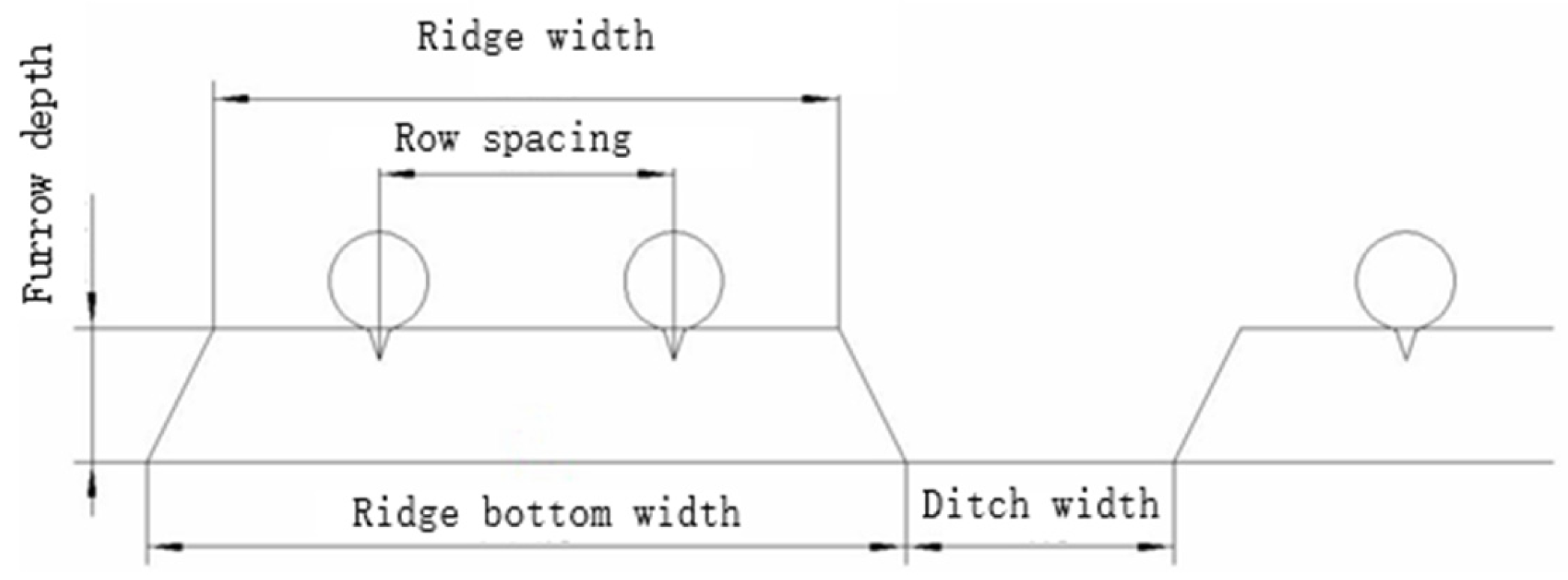
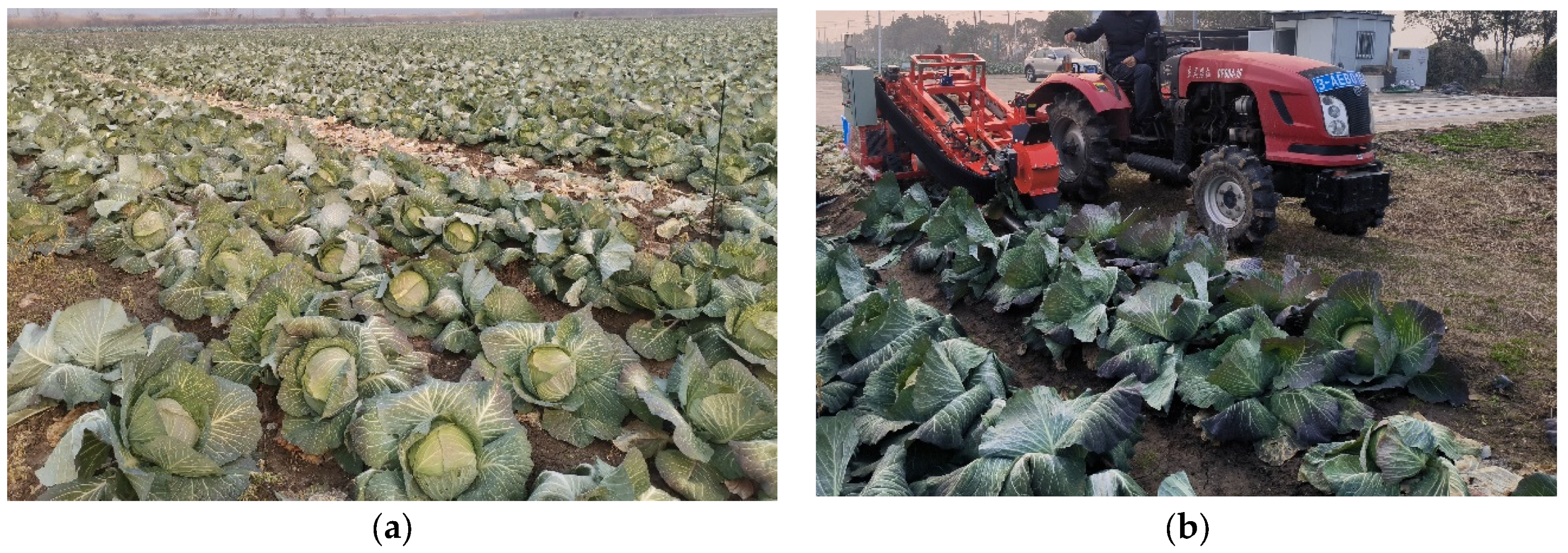
2.1. Main Cultivation Methods and Mechanization Requirements

Cabbage thrives in warm, cool, and moist climates, with an optimal growth temperature range of 15–25 °C. The leaves are low in fiber, tender, and juicy. Cabbage is widely cultivated across China, with the most concentrated planting areas in Jiangsu, Shandong, Henan, and Hebei provinces, which together account for approximately 55% of the total cabbage cultivation area in the country [15]. In Jiangsu, the early stages of cabbage cultivation—such as land preparation, transplanting, and field management have largely been mechanized. However, harvesting is still primarily carried out manually. To enhance the versatility of the designed cabbage harvester, standardized and commonly used ridge cultivation methods and agronomic parameters in Jiangsu were selected as the design basis. The typical planting method, shown in Figure 1, involves a dual-row ridge pattern with a row spacing of 400–500 mm, plant spacing of 400–500 mm, furrow depth of 150–200 mm, ditch width of 200–300 mm, ridge width of approximately 700 mm, and ridge bottom width of approximately 850 mm. The planting density ranges from 48,000 to 55,500 plants per hectare [1].
The mechanized cabbage harvesting process primarily comprises five stages: extraction, clamping and conveying, root-cutting, and packaging. These stages operate in coordination to complete the overall harvesting process. Due to the uneven ridge surfaces and irregular plant spacing, a single-row harvesting method was selected. To balance design costs and promote wider adoption, a tractor-mounted, side-hanging design was chosen, which helps reduce both design and purchase expenses. Furthermore, to minimize environmental impact and lower harvesting costs, the system is powered electrically.

2.2. Overall Structure

Based on the characteristics of both domestic and international cabbage harvesters, as well as the planting methods prevalent in Jiangsu Province, a harvesting method involving extraction followed by clamping, conveying, and root cutting was identified. A side-mounted, single-row cabbage harvester, designed for use with a 50-horsepower tractor, was subsequently developed. The overall structure is shown in Figure 2. The machine consists of a three-point hitch device, a battery, a collection frame, and a harvesting section. The harvesting section includes a leaf-stripping device, an extraction device, a clamping and conveying device, and a root-cutting device. The DC power supply and the collection frame are mounted on the three-point hitch device. The entire harvesting section is also installed on the three-point hitch device and is connected to two electric push rods, which are used to control the lifting and lowering of the harvesting section. The three-point hitch device is connected to the tractor. The power is entirely provided by a 48 V–120 Ah DC power supply, which allows for the complete execution of operations such as pulling, clamping, conveying, root cutting, and boxing of cabbage in a single process. According to calculations, the cabbage harvester can operate continuously for three hours in a single session, meeting the requirements for harvesting experiments.

2.3. Working Principle and Technical Parameters

During operation, the cabbage harvester uses an electric actuator to adjust the inclination angle of the harvesting unit relative to the ground to 20–30° [10]. This adjustment ensures that the lower surface of the extraction rollers maintains close contact with the ground and aligns with the cabbage row. Prior to beginning the experiment, adjustments must be made based on the size of the cabbage to be harvested. These adjustments include the spacing and angle of the extraction rollers, the spacing of the clamping and conveying device, and the vertical and horizontal positions of the leaf-stripping wheel and cutting device.
As the machine advances, a pair of extraction rollers penetrates the base of the cabbage, lifting it and conveying it backward. When the cabbage reaches the end of the extraction rollers and enters the clamping and conveying device, it is clamped by the clamping and conveying device under the continuous pressure exerted by the leaf-stripping device. The root-cutting device then completes the root-cutting process while the cabbage is held by the clamping and conveying device. Finally, the cabbage falls into the collection frame at the end of the clamping and conveying device, completing the entire harvesting process. The extraction rollers, clamping and conveying device, leaf-stripping device, and root-cutting device can be flexibly adjusted to accommodate different operating conditions, making the machine adaptable to the mechanized harvesting requirements of various cabbage varieties and sizes. The main parameters are listed in Table 1.

3. Key Component Structure Design and Motion Analysis

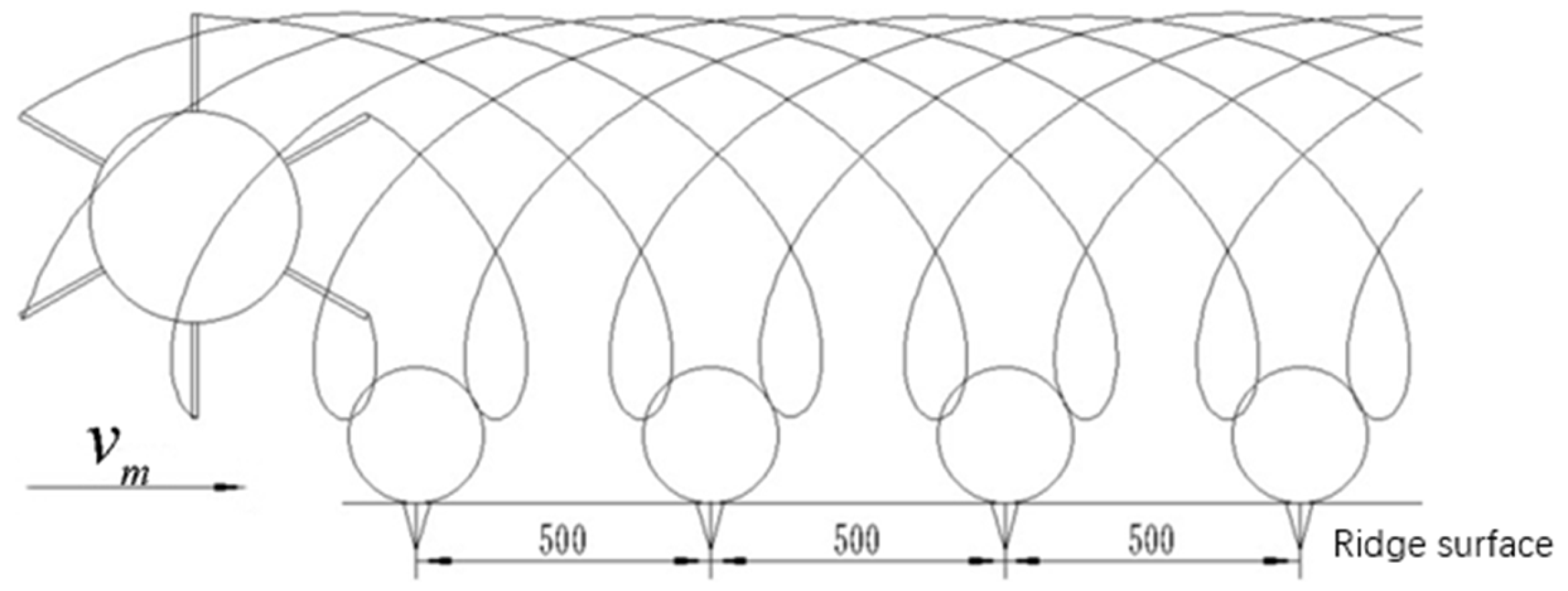
3.1. Extraction Device

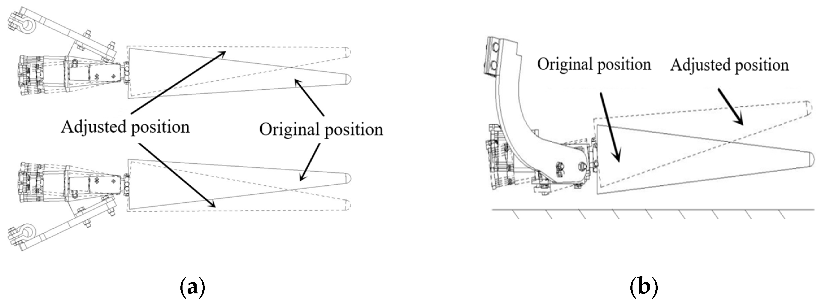
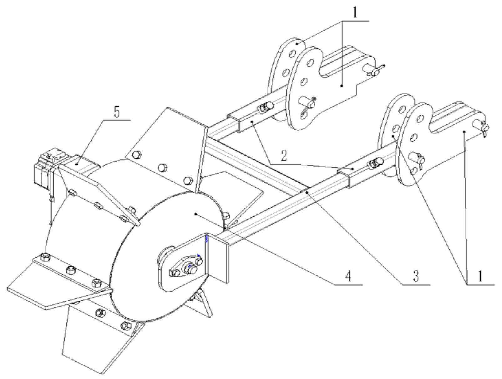
3.1.1. Extraction Device Structure Design

The extraction device primarily comprises a pair of extraction rollers, roller connectors, positioning mounts, and a roller adjustment plate. During cabbage harvesting experiments in various planting scenarios with different cabbage sizes, the angle of the extraction rollers can be modified by adjusting the relative position between the positioning mounts and the roller adjustment plate, as depicted in Figure 3a. The designed adjustable range for the extraction rollers’ opening angle is 0–13°. Furthermore, the inclination angle of the extraction rollers can be adjusted by altering the relative position between the roller connector and the roller adjustment plate, as shown in Figure 3b. The designed adjustable range for the rollers’ inclination angle is 0–15°.

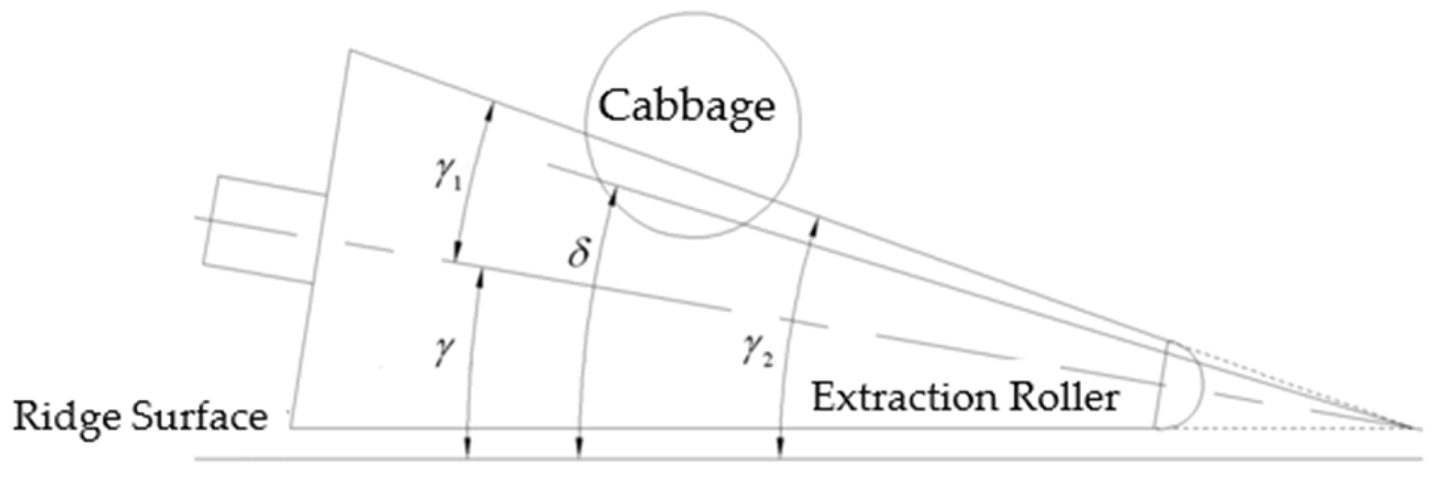
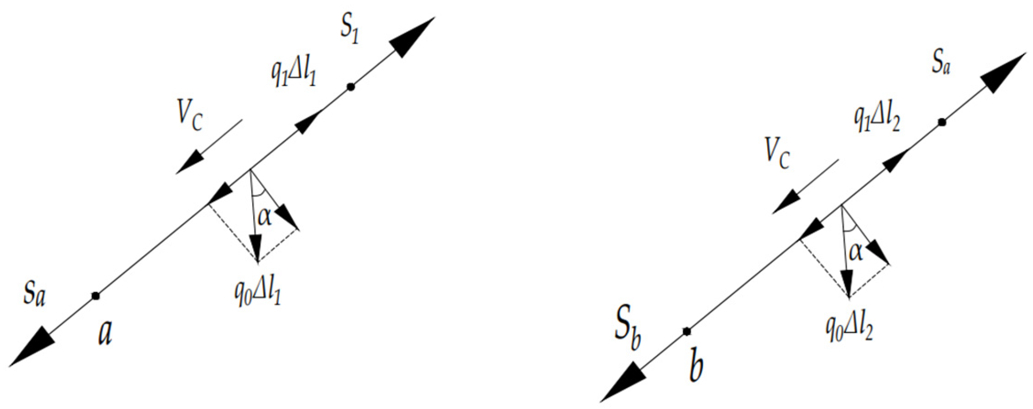
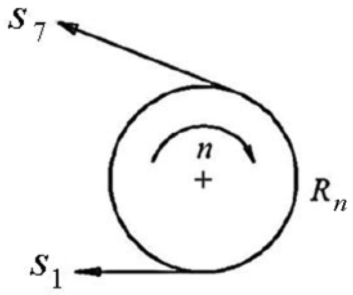
3.1.2. Extraction Device Motion Analysis

To facilitate calculations and analysis, the system comprising the extraction rollers and the cabbage is modeled as a rigid body system. For simplification, the rigid body model is further refined by assuming that the cabbage’s center of mass remains constant throughout the extraction process. Based on this assumption, the interaction between the cabbage and the extraction device during the extraction process is analyzed. The kinematic analysis of the system is illustrated in Figure 4. m represents the mass of the cabbage plant, m j represents the mass of the extraction rollers, a j represents the absolute acceleration of the harvesting test platform, a r represents the forward acceleration of the harvesting test platform, F M denotes the reaction force exerted by the ground on the extraction rollers, F j indicates the extraction force exerted by the rollers on the cabbage, f N represents the frictional force between the rollers and the surface of the cabbage, μ is the coefficient of friction between the cabbage and the rollers, K M represents the mass ratio between the extraction rollers and the cabbage plant, and δ is the angle between the line connecting the contact point of the cabbage and the extraction rollers and the tip of the rollers with the ground.
Based on the system’s center of mass motion theorem, the dynamic equations in the X and Z directions can be derived and established as follows [16,17]:
m a x = F X e m j a j + m a j a r cos δ = F j sin δ m a Z = F z e F M m j + m g F j cos δ = m a r sin δ
The force analysis diagram of the cabbage is shown in Figure 5.
By applying the center of mass motion theorem, the dynamic equations of cabbage in the X and Z directions can be derived as follows:
m a x = F X e m g sin δ μ F j = m a j cos δ a r m a Z = F Z e F j m g cos δ = m a j sin δ
From Equation (2), we obtain the following:
  a r = a j μ sin δ + cos δ g sin δ μ cos δ
From Equations (1) and (2), we obtain the following:
a r = a j m cos δ + m g sin δ cos δ m + m j m   sin 2 δ = a r cos δ + g sin δ cos δ K M + cos 2 δ
By combining Equations (3) and (4), we obtain the following:
a r = g μ K M cos δ sin δ + μ cos δ K M μ sin δ cos δ
To ensure that the cabbage moves upward along the surface of the extraction rollers during the extraction process, a r > 0 must be guaranteed. Given that δ is less than 45°, the condition for the cabbage to move upward along the surface of the extraction rollers during the extraction process, as derived from Equation (4), is as follows:
  μ K M + 1 > tan δ cos 2 δ
Based on Equation (6), the friction coefficient μ between the cabbage and the extraction rollers, the angle δ between the contact point of the cabbage and the extraction rollers, as well as the mass ratio K M between the extraction rollers and the cabbage, all influence the effectiveness of the cabbage extraction. A higher friction coefficient μ between the cabbage and the extraction rollers is more conducive to effective extraction. Therefore, when selecting materials for the extraction rollers, it is essential to choose materials that are smooth, rust-resistant, and wear-resistant. In this study, 304 stainless steel was selected as the roller surface material [18].
Moreover, the angle δ between the contact point of the cabbage and the extraction rollers also affects the extraction effectiveness. This angle δ is determined by the inclination angle and the design dimensions of the extraction rollers, as illustrated in Figure 6.
In the figure, γ 1 represents the inclination angle of the extraction roller, γ 2 denotes the angle between the extraction roller’s generatrix and the axis, and γ 2 indicates the angle between the extraction roller’s generatrix and the ridge surface. During actual operation, the contact point between the cabbage and the extraction roller is always located above the roller’s axis and below the generatrix, leading to the relationship γ < δ < γ 2 , where γ , γ 1 , and γ 2 satisfy the following equation:
γ 2 = γ 1 + γ
Based on the dimensions of the extraction roller designed in this study, γ 1 is 5°, and the adjustable range of the extraction roller’s inclination angle γ is 0–5°. According to Equation (7), the range of γ 2 is 5–10°. Since γ < δ < γ 2 , the range of δ is 0° < δ < 10°. The weight of the extraction roller, calculated using SolidWorks’ built-in mass calculation feature, is 3.83 kg.
Using Equation (6), the following function of δ can be established:
f ( δ ) = tan δ cos 2 δ
From Equation (6), it is evident that as δ increases within the range of 0° < δ < 10°, it becomes less favorable for cabbage extraction. The measured friction coefficient between the cabbage and the extraction roller is 0.8. The maximum weight of commonly cultivated cabbage varieties in Jiangsu Province, China, is 2.84 kg, resulting in a K M value of 1.35. Therefore, based on Equation (6), to ensure that the cabbage moves upward along the surface of the extraction roller during the extraction process, the design parameters of the extraction roller must satisfy the following conditions:
f ( δ ) = tan δ cos 2 δ < 0.34
Since f ( δ ) is an increasing function when 0° < δ < 10° and f ( 10 ° ) = 0.18 < 0.34, the structural parameters of the extraction roller designed in this study can effectively ensure that the cabbage moves upward along the surface of the roller during the extraction process, validating the design.

3.2. Leaf-Stripping Device

3.2.1. Leaf-Stripping Device Structure Design

As a key component of the adjustable extraction mechanism, the overall structure of the designed leaf-stripping device is illustrated in Figure 7. The adjustment plate for the leaf-stripping wheel is securely mounted at the front end of the main frame. The mounting tube for the leaf-stripping wheel is rotationally attached to the adjustment plate. By adjusting the relative position between the adjustment plate and the mounting tube, the inclination angle of the mounting tube can be altered, allowing the working height of the leaf-stripping wheel to be tailored to the size of the cabbage. This feature ensures that the mechanism can effectively handle the extraction process for cabbages of various sizes. The mounting frame for the leaf-stripping wheel is designed in a tubular form and is nested within the mounting tube. During the experiment, the protruding length of the mounting frame can be manually adjusted within a range of 0–25 mm to accommodate different cabbage varieties and sizes.

3.2.2. Leaf-Stripping Device Motion Analysis

When the cabbage harvesting test platform is operating normally, the forward motion of the platform, combined with the rotational motion of the leaf-stripping wheel, constitutes the overall movement of the leaf-stripping wheel [19]. The motion trajectory of the leaf-stripping wheel can be expressed by the ratio λ of the peripheral speed of the wheel v y to the forward speed of the harvesting platform v m [20]:
λ = v y v m
where v y is the peripheral speed of the leaf-stripping wheel, m s−1, and v m is the forward speed of the harvesting platform, m s−1.
The value of λ ranges from 0 to ∞; when the value of λ ranges from 0 to 1, the trajectory of the leaf-stripping wheel is a short-length cycloid; when λ is 0, the trajectory becomes a straight line. The cabbage can only be effectively aligned and pushed by the leaf-stripping wheel when the wheel has a backward component of velocity. When λ > 1 does the lower part of the leaf-stripping wheel generate a backward velocity component during operation. Therefore, in the parameter design of the leaf-stripping wheel, λ must be greater than 1. However, as the value of λ increases, the impact speed and frequency of the wheel’s blades on the cabbage also increase, which can lead to cabbage damage. Thus, in addition to ensuring the basic operational requirements of the leaf-stripping wheel, it is also necessary to consider minimizing damage to the cabbage [21].
Assuming the leaf-stripping wheel has m evenly distributed blades, the forward distance s covered by the harvesting platform for each blade rotation of the wheel is as follows:
s = v m 60 m n r
where m is the number of blades on the leaf-stripping wheel, blade, and n r is the rotational speed of the leaf-stripping wheel, RPM.
Taking the projection point 0 of the wheel’s axis on the ground as the origin of the coordinate system, with the positive direction of the X-axis being the forward direction of the cabbage harvesting platform and the Y-axis being vertically upward as the positive direction, the trajectory of a point A0 on the outer edge of the leaf-stripping wheel, starting from the horizontal position and rotating clockwise, can be expressed as follows:
x = v m t + R r cos ω r t y = H r R r sin ω r t
where R r is the radius of the leaf-stripping wheel, m; ω r is the angular velocity of the leaf-stripping wheel, rad s−1; and H r is the vertical distance from the leaf-stripping wheel to the ground, m.
To ensure that the blades of the leaf-stripping wheel effectively push the cabbage towards the floating flexible clamping and conveying mechanism at the feed inlet, the distance between two adjacent blades of the leaf-stripping wheel during normal operation must be sufficient to accommodate the next cabbage. Therefore, the diameter of the leaf-stripping wheel should be determined using the following formula:
2 π R r m > D b
where D b is the diameter of the cabbage head, mm.
For the common cabbage variety in Jiangsu Province, China, the number of blades on the leaf-stripping wheel is set to 6, and the radius of the wheel is 360 mm.
To achieve continuous operation in the cabbage harvesting experiment, the blades of the leaf-stripping wheel need to act on the cabbage head continuously or at regular intervals. To meet this requirement, the pitch S r between the cycloid hooks of the leaf-stripping wheel should satisfy the following equation [22,23]:
S r = 2 π R r m λ = S p z
where S r is the pitch between the cycloid hooks of the leaf-stripping wheel, mm; S P is the cabbage plant spacing, mm; and z is the interval quantity of the leaf-stripping wheel blades, generally set to 1, 2, or 3 [11].
Given a cabbage plant spacing of 400–500 mm, with the number of blades set to 6, the leaf-stripping wheel radius at 360 mm, and z value of 2, the value of λ is calculated to be between 1.51 and 1.89, with all λ values greater than 1. Based on the determined dimensions of the leaf-stripping wheel, the rotational speed n r can be determined by the following formula:
n r = 30 λ v m π R r
To verify the accuracy of this calculation, the working diagram of the leaf-stripping wheel was plotted using λ = 1.51 and v m = 0.1 m s−1 as an example. As shown in Figure 8, the motion trajectory of the designed leaf-stripping wheel forms a long cycloid, demonstrating a reasonable design that can successfully achieve the tasks of aligning and pushing the cabbage.

3.3. Clamping and Conveying Device

3.3.1. Clamping and Conveying Device Structure Design

As shown in Figure 9, the clamping and conveying device developed in this study primarily comprises a main frame, a tensioning arm assembly, and additional mechanisms. The tensioning arm assembly, which forms the core of the device, includes a tensioning arm mounting tube, a tensioning arm, a tensioning arm end cap, a tensioning wheel, an outer guard for the tensioning wheel, and a tension spring for the tensioning arm. To facilitate adjustable clamping force and distance, the tension spring is connected to the tensioning arm at one end and to an adjustment piece mounted on screw rods located on both sides of the main frame at the other end. By adjusting the position of this adjustment piece along the screw rod, the preload exerted by the tensioning wheel on the conveyor belt can be modified. Given that the diameter of commonly cultivated cabbage varieties in the Jiangsu region of China ranges from 120 to 240 mm, the clamping and conveying device has been designed with an adjustable clamping distance ranging from 80 to 280 mm.

3.3.2. Clamping and Conveying Device Motion Analysis

To determine the tension in both the working and non-loaded sections of the conveyor belt, this study employs the point-by-point tension method for mechanical analysis, thereby establishing a mechanical model for the clamping and conveying mechanism [24]. For simplicity in the calculation, the following assumptions were made during the mechanical analysis of the floating flexible clamping and conveying device: (1) the force exerted by the tensioning wheel on the conveyor belt is assumed to be equal in magnitude and uniformly distributed across the working section of the belt; (2) the influence of the swing of the driven roller assembly on the mechanical model is neglected; and (3) the elastic sliding of the conveyor belt within the guide slots of the main and driven rollers, as well as the tensioning wheel, is ignored.
The simplified schematic diagram of the clamping and conveying device is shown in Figure 10. In the working section of the conveyor belt, a tensioning wheel is positioned between the driving and driven rollers, while in the non-loaded section, a support and limiting mechanism with carrier rollers and support wheels is present.
During the operation of the clamping and conveying system, the conveyor belt can be divided into two sections based on its working state: the working section and the non-loaded section. The non-loaded section refers to the conveyor belt between points 1 and 2, while the working section covers the belt between points 3 and 7. The tension in the non-loaded section is first analyzed and calculated: In Figure 11, within the non-loaded section, two adjacent points a and b are arbitrarily selected in the middle portion, with Δ l 1 representing the length from point a to point 1, Δ l 2 representing the length from point a to point b, and s representing the tension experienced at various points along the conveyor belt.
The tension at points a and b can be derived using the point-by-point tension method for the segment from point 1 to point a. The tension at points a and b can be expressed as follows:
s a = s 1 + q 1 Δ l 1 q 0 Δ l 1 sin α
s b = s a + q 1 Δ l 2 q 0 Δ l 1 sin α
where q 0 is the weight of the conveyor belt per unit length, N m−1; q 1 is the friction force per unit length between the conveyor belt and the carrier roller in the non-loaded section, N m−1; and α is the inclination angle of the conveyor belt relative to the ground, °.
From Equations (16) and (17), we obtain the following:
s b = s 1 + q 1 Δ l 1 + Δ l 2 q 0 Δ l 1 + Δ l 2 sin α
s b = s 1 + q 1 l 1 b q 0 l 1 b sin α
Similarly, the tension at point 2 in the non-loaded section can be expressed as follows:
s 2 = s 1 + q 1 l 12 q 0 l 12 sin α
Neglecting the effects of bearing friction, the swing of the driven roller assembly on the mechanical model, and the elastic sliding of the conveyor belt in the guide slots of the main and driven rollers and the tensioning wheel, the tension at point 2 is equal to the tension at point 3, so we have the following:
s 3 = s 2 = s 1 + q 1 l 12 q 0 l 12 sin α
For the force analysis at point 4 on the conveyor belt, the tension at point 4 is as follows:
s 4 = s 3 + q 0 l 34 sin α
Substituting Equation (21) into Equation (22), we obtain the following:
s 4 = s 1 + q 0 l 34 l 12 sin α + q 1 l 12
To analyze the conveyor belt between points 4 and 5, select two points, c and d. Let the distance from point c to point 4 be denoted as Δ l 3 , and the distance from point c to point d be denoted as Δ l 4 . The force analysis of the conveyor belt between points 4 and 5 is illustrated in Figure 12. Using the point-by-point tension method, the force balance equations at points c and d can be derived and established as follows:
s c = s 4 + q 0 Δ l 3 sin α + q 3 Δ l 3 sin α + q 2 Δ l 3
s d = s c + q 0 Δ l 4 sin α + q 3 Δ l 4 sin α + q 2 Δ l 4
where q 2 is the friction force between the conveyor belt and the tensioning wheel in the segment from point 4 to point 6, N m−1, and q 3 is the gravitational force of the cabbage on the conveyor belt in the segment from point 4 to point 6, N m−1.
Using Equations (23)–(25), the tension at point d can be expressed as follows:
s d = s 1 + q 1 l 12 + q 0 l 34 l 12 sin α + q 0 + q 3 l 4 d sin α + q 2 l 4 d
Similarly, the tension at point 5 on the conveyor belt in the working section is given by the following:
s 5 = s 1 + q 1 l 12 + q 0 l 34 l 12 sin α + q 0 + q 3 l 45 sin α + q 2 l 45
By following the same approach, the tensions at points 6 and 7 on the conveyor belt in the working section can be determined as follows:
s 6 = s 1 + q 1 l 12 + q 0 l 34 l 12 sin α + q 0 + q 3 l 46 sin α + q 2 l 46
s 7 = s 6 + q 0 l 67 sin α
s 7 = s 1 + q 1 l 12 + q 0 l 34 l 12 + l 67 sin α + q 0 + q 3 l 46 sin α + q 2 l 46
The force analysis of the driving roller is shown in Figure 13. Let R n represent the radius of the driving roller. The maximum tension experienced by the conveyor belt occurs at point 7 in Figure 10, while the minimum tension occurs at point 1 in Figure 10. The driving torque of the roller can be expressed as follows:
T 1 = R n q 1 l 12 + q 0 l 34 l 12 + l 67 sin α + q 0 + q 3 l 46 sin α + q 2 l 46
The conveyor belt consists of a two-layer structure: the outer side is made of 45D high-density foam, and the inner side is a canvas and nylon belt with two rubber guide strips.
The reason for choosing this sponge is due to its high density, strong toughness, and quick rebound ability. After calculation, the gravity per unit length of the conveyor belt, q 0 , is 19.26 N m−1. According to the design manual, the simulated friction coefficient between the conveyor belt and the carrier roller is 0.022, so the friction force per unit length in the non-loaded section between the conveyor belt and the carrier roller, q 1 , is 0.42 N m−1 [25,26].
The cabbage planting spacing is set to 400 mm, and the floating flexible clamping and conveying device can hold up to five cabbages. The crushing force of a cabbage head is approximately 1200 N, so the maximum clamping force is set to 1200 N. With a simulated friction coefficient of 0.022, the maximum friction force per unit length between the conveyor belt and the tensioning wheel in this section from point 4 to point 6, q 2 is 62.86 N m−1. The maximum weight of the widely cultivated cabbage in Jiangsu Province is 2.84 kg, and the clamping and conveying device can hold up to 5 cabbages. Thus, the maximum gravitational force per unit length on the conveyor belt in this section from point 4 to point 6, q 3 is 33.13 N m−1.
In summary, according to Equation (17), the driving torque of the roller is calculated to be 16.15 Nm. Based on available data, and referring to the current clamping and conveying mechanisms used for cabbage harvesting in China with dual transverse conveyor belts, the maximum rotational speed of the driving roller in this design is determined to be 57 RPM [27,28]. With a mechanical efficiency of 0.9, the required power for the driving roller motor is 107.1 W. A 300 W DC brushless motor with a reducer, rated at 60 RPM, is selected to meet the power requirements of the clamping and conveying device.

3.4. Root-Cutting Device

3.4.1. Root-Cutting Device Structure Design

Root cutting is a crucial step in the mechanized harvesting of cabbage. The adjustable root-cutting device designed in this study primarily consists of a cutter frame, screw lifter, cutter motor, cutter mounting plate, and cutter, as illustrated in Figure 14. The screw lifter is secured between the main frame and the cutter mounting frame, allowing for the adjustment of the cutter mounting plate’s position relative to the main frame. This adjustable root-cutting mechanism can achieve a variable distance between the cutter and the conveyor belt within a range of 8 to 40 mm, facilitating the effective cutting of roots for different cabbage varieties and sizes.

3.4.2. Root-Cutting Device Motion Analysis

To analyze the forces involved in the root-cutting process of the adjustable root-cutting device designed in this study, refer to Figure 15 [29,30,31].
When the cabbage is clamped and conveyed by the clamping and conveying device to the cutter of the root-cutting mechanism, the primary forces acting on the cabbage roots by the cutter include the cutting force Q x and the clamping force P y . In the diagram, ω p represents the rotational speed of the cutter. The force balance equations are given as follows:
Q x = F N x + T x P y = T y F N y T = F N f T y = F N f cos α F N y = N sin α
where T is the frictional force between the cutter and the cabbage root, N; F N is the normal force exerted by the cutter on the cabbage root, N; f is the coefficient of friction between the cutter and the cabbage root, generally taken as 0.7; and α is the angle between the normal force of the cutter on the cabbage root and the X-axis, °.
The condition for the cabbage root to be effectively clamped by the double-disk cutter is as follows:
P y > 0
In summary, for the double-disk cutter to achieve an optimal clamping effect, the following conditions must be met:
f > tan α
That is:
F N f cos α F N sin α > 0
The angle α can be calculated using the following formula:
α = arccos A D + d
where A is the center distance between the two disk cutters, mm; D is the diameter of the disk cutter, mm; and d is the diameter at the cutting position of the cabbage root, mm.
Since the coefficient of friction and the diameter of the cutter are fixed values, the key parameter affecting the clamping effect of the double-disk cutter mechanism is the center distance of the cutters. The optimal cutting position for cabbage roots is 10 to 15 mm above the base leaves, where the root diameter ranges from 30 to 32 mm [10]. From Equation (36), the range of cutter center distances that satisfies Equation (35) is 188–199 mm, corresponding to an overlapping region of 1–12 mm for the double-disk cutters. The adjustable root-cutting mechanism designed in this study allows for an adjustable cutter overlap region of 0–30 mm, enabling effective cutting of cabbage roots of varying diameters.

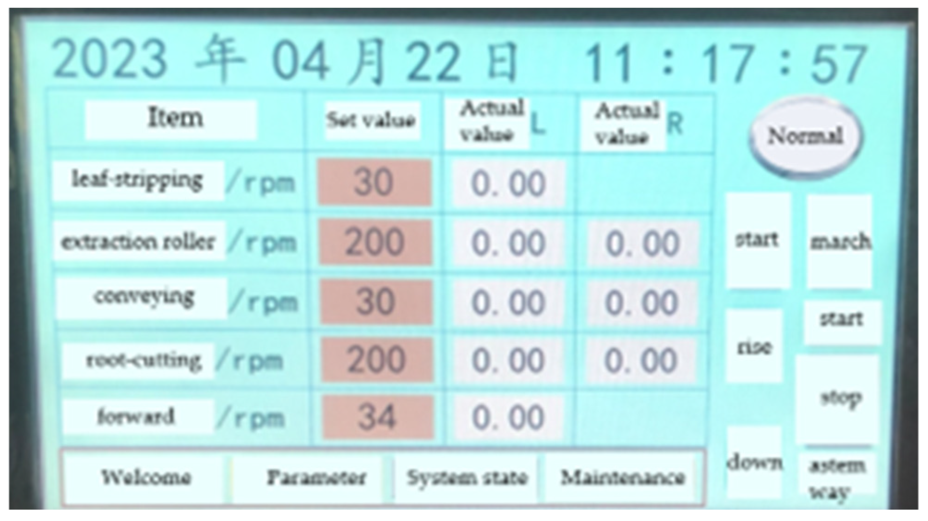
3.5. Selection and Design of the Control System

The harvesting operations on the test bench are a continuous process, requiring precise coordination between the various actuating mechanisms to ensure smooth execution. To address this need, a closed-loop control strategy was adopted in this study. The motor’s Hall sensor detects the rotor’s position and speed, generating pulse signals that transmit the current position and speed information to the controller. The controller calculates the current motor speed and compares it with the set speed. If there is a discrepancy between the actual and set speeds, the controller adjusts the motor current to bring the actual speed closer to the target value. This approach allows for precise control of the motor speed, ensuring that the motor consistently operates within the desired speed range, thereby improving motor performance and stability.
The control system of the harvesting test bench designed in this study has several key functions: it controls the start, stop, and real-time speed adjustment of the chassis motor, the start, stop, and real-time speed monitoring and adjustment of the harvesting motor, the raising and lowering of the electric push rod, error, and fault display, and an emergency stop function for the entire machine. The human–machine interface panel is shown in Figure 16.

4. Field Experiment

4.1. Experimental Conditions

The designed electric side-mounted cabbage harvester was field tested on 27 December 2023 at the agricultural machinery cooperative’s planting base in Hengtang, Changshu, Jiangsu Province (Figure 17a,b). The experimental site selected five rows of well-growing cabbages. The cabbage variety planted at this base was “Aojina”, which was grown using a two-row-per-ridge planting method. The ridge height ranged from 144 to 168 mm, the ridge base width from 1150 to 1250 mm, the furrow width from 214 to 246 mm, the row spacing from 480 to 580 mm, and the plant spacing from 380 to 470 mm. The cabbage heads were flattened and spherical, with a total mass ranging from 2.63 to 5.83 kg, a head diameter of 206 to 286 mm, a plant height of 194 to 326 mm, a root height of 50 to 112 mm, and an extraction force of 119 to 223 N.

4.2. Experimental Methods and Results

Due to the lack of relevant standards and regulations for mechanized cabbage harvesting, this field experiment was conducted based on GB/Z 26582-2011 “technical regulations for cabbage harvesting production” and JB/T 6276-2007 “test methods for beet and harvesting machinery” [32,33]. The performance evaluation indicators for the cabbage harvester include the success rate of extraction, the success rate of conveying, and the harvest loss rate.
To evaluate the performance of this cabbage harvester in the processes of extraction, clamping, and root cutting, the extraction roller speed, conveyor belt speed, and cutter speed were first identified as the experimental factors. The initial level of the extraction roller speed was set at 100 RPM, the initial level of the conveyor belt speed at 50 RPM, and the initial level of the cutter speed at 180 RPM [11,12]. By using the control variable method, one experimental factor was changed at a time, while keeping the others constant. Each group of experiments was repeated 5 times, with 60 cabbages harvested each time.
(1)
Single-factor experiment on extraction roller speed: During the experiment, the conveyor belt speed was fixed at 60 RPM, and the cutter speed was fixed at 180 RPM. The extraction roller speed started at 80 RPM, increasing by 10 RPM in each subsequent test. A total of five groups of experiments were conducted, with the maximum extraction roller speed reaching 120 RPM.
Single-factor experiment on conveyor belt speed: During the experiment, the extraction roller speed was fixed at 100 RPM, and the cutter speed was fixed at 180 RPM. The conveyor belt speed started at 40 RPM, increasing by 10 RPM in each subsequent test. A total of five groups of experiments were conducted, with the maximum conveyor belt speed reaching 80 RPM.
(2)
Single-factor experiment on cutter speed: During the experiment, the conveyor belt speed was fixed at 60 RPM, and the extraction roller speed was fixed at 100 RPM. The cutter speed started at 140 RPM, increasing by 20 RPM in each subsequent test. A total of five groups of experiments were conducted, with the maximum cutter speed reaching 220 RPM.
In this experiment, the success rate of extraction, the success rate of conveying, and the harvest loss rate were selected as performance evaluation indicators for the cabbage harvester. The definitions of each experimental indicator are as follows:
(1)
Success Rate of Extraction
The success rate of extraction refers to the proportion of cabbage plants that are successfully pulled by the double-helix extraction device and smoothly enter the clamping device. During the experiment, the number of successfully pulled cabbages is measured, with the calculation as follows:
Y C = Q C Q × 100
where Y C is the success rate of extraction, %; Q C is the number of successfully pulled cabbages; and Q is the total number of cabbages harvested.
(2)
Success Rate of Conveying
The success rate of conveying refers to the proportion of successfully pulled cabbages that are conveyed by the conveyor belt without falling and maintaining their posture during the clamping process. During the experiment, the number of successfully conveyed cabbages is measured, with the calculation as follows:
Y D = Q D Q C × 100
where Y D is the success rate of conveying, %, and Q D is the number of cabbages successfully conveyed.
(3)
Root-Cutting Qualification Rate
The root-cutting qualification rate refers to the proportion of cabbages that meet the criteria after root cutting by the cutting device. The criteria for qualified root cutting include the following: (1) the cutting surface must be smooth without breaking or having two cutting surfaces; (2) the cutting position must be 10–15 mm above the outer wrapper leaves, and the outer wrapper leaves should be cut off. During the experiment, the number of cabbages that meet the root-cutting qualifications is measured, with the calculation as follows:
Y K = Q K Q D × 100
where Y K is the root-cutting qualification rate, %, and Q K is the number of cabbages that qualify after root cutting.
(4)
Harvest Loss Rate
The harvest loss rate refers to the proportion of cabbages lost due to machine harvesting operations, including those that were not successfully pulled, and those damaged during clamping, conveying, root cutting, and boxing operations. During the experiment, the number of cabbages lost due to machine operations is measured, with the calculation as follows:
  Y L = Q L Q × 100
where Y L is the harvest loss rate, %, and Q L is the number of cabbages lost due to machine harvesting operations.
The results of the single-factor experiments are shown in Table 2, Table 3 and Table 4.
In the single-factor experiment, the types of cabbage harvesting damage and the successfully harvested cabbages are shown in Figure 18.

5. Discussion

Based on the test results from the three harvesting stages—extraction, conveying, and cutting—the average conveying success rates across the three sets of experiments were 99%, 99.3%, and 99.3%, respectively. Similarly, the average root-cutting qualification rates were 98.6%, 98.6%, and 98.3%, all of which are notably high. These results indicate that once the cabbage successfully enters the conveyor belt, it remains secure without falling off or shifting during the conveying process. Additionally, the stability provided by the conveyor belt’s clamping mechanism during root cutting prevents any tilting or damage, thus ensuring high cutting quality. The impact of the clamping and conveying stage on the root-cutting stage is minimal. It also validated the reliability of the previously designed clamping and conveying device as well as the root-cutting device. However, the average extraction success rate was less than ideal, recorded at 90%, 89.7%, and 90%, respectively. One contributing factor is that the cabbage variety harvested in this experiment had an average weight of 4 kg, with a maximum middle diameter of 286 mm, resulting in significant size variations. Larger cabbages exceeded the machine’s harvesting range of 80–280 mm. Additionally, the row spacing of the cabbages varied widely, between 480 and 580 mm, causing some cabbages to fall outside the extraction roller’s reach, making them unharvestable. This suggests a need for further refinement in agricultural practices. Moreover, parameters such as the angle and tension of the conveyor belt’s opening, and the relative position of the extraction roller to the conveyor belt, are critical at the transition point where the cabbage is about to enter the clamping and conveying device. However, due to design constraints, these parameters could not be optimally adjusted in the test field, leading to suboptimal harvesting outcomes. Further optimization of key mechanical structures is necessary. Additionally, the walking speed influences the success rate of cabbage entering the clamping and conveying device and should be considered as a parameter in future experiments.
Regarding the harvesting loss rate, the average results for the three groups were 11.3%, 13.3%, and 12%, which meet the design requirements of this cabbage harvester. The extraction stage was the most significant factor contributing to these losses. Cabbages that were not successfully pulled did not smoothly enter the clamping and conveying device, or they changed position before entering, which inevitably led to damage during the cutting process and, consequently, harvest losses.
Among the three experimental factors—extraction roller speed, conveyor belt speed, and cutter speed—variation in conveyor belt speed had the most significant impact on the test results, particularly on the extraction success rate. The maximum extraction success rate reached 93.3%, while the minimum was 86.7%, resulting in a difference of 6.6%. The main reason is that changes in conveyor belt speed, while the walking speed remains constant, significantly affect the success rate of cabbages entering the conveyor belt, which in turn impacts the extraction success rate. Therefore, walking speed must be included as an experimental parameter in the next test. Additionally, further experiments on different cabbage varieties are needed to verify the performance of the cabbage harvester.

6. Conclusions

(1)
A single-row electric side-mounted cabbage harvester was designed, utilizing a tractor-drawn operation method with a three-point hitch to connect to the tractor. The extraction device employs double helical rollers, and an adjustable clamping and conveying device was designed, where the clamping gap can be modified. The conveyor belt’s exterior is made of a 45D high-density sponge, which tightly wraps around the cabbage, preventing clamping damage and achieving a higher root-cutting qualification rate. The root-cutting device is adjustable within a range of 8 to 40 mm, allowing for flexible adjustments based on different cabbage varieties. The reliability of each component was verified through motion analysis.
(2)
Field tests demonstrated that this electric side-mounted cabbage harvester can complete the tasks of extraction, conveying, root cutting, and boxing in a single operation, proving the design scheme’s reliability. When the extraction roller speed is set between 100 and 110 RPM, the conveyor belt speed is at 60 RPM, and the cutter speed is between 160 and 220 RPM, the cabbage harvest loss rate is minimized. The single-factor tests yielded harvest loss rates of 11.3%, 13.3%, and 12%, respectively, meeting the design requirements of the cabbage harvester. Therefore, the design presented in this paper can serve as a reference for the design of cabbage harvesters, particularly those capable of harvesting different cabbage varieties.

Author Contributions

Conceptualization, Z.L. (Ze Liu) and H.M.; methodology, H.M.; software, Z.L. (Zhikang Li); validation, Z.L. (Ze Liu), E.W., Y.Y. and M.Z.; investigation, Z.L. (Ze Liu); resources, Z.L. (Ze Liu); data curation, Z.L. (Ze Liu) and E.W.; writing—original draft preparation, Z.L. (Ze Liu); writing—review and editing, Z.L. (Ze Liu) and H.M.; visualization, Z.L. (Ze Liu); supervision, H.P.; project administration, H.M. and Z.Z. All authors have read and agreed to the published version of the manuscript.

Funding

This research was funded by the China Agriculture Research System (CARS-23-D03), a project funded by the Priority Academic Program Development of Jiangsu Higher Education Institutions (Jiangsu Education Department, Grant No. PAPD-2023-87).

Institutional Review Board Statement

Not applicable.

Data Availability Statement

The data presented in this study are available on request from the corresponding author.

Conflicts of Interest

The authors declare no conflicts of interest.

References

  1. Tong, W.Y.; Zhang, J.F.; Song, Z.Y. Research status and development trend of cabbage mechanical harvesting equipment and technology. J. Chin. Agric. Mech. 2024, 45, 322–329. (In Chinese) [Google Scholar]
  2. Zou, L.L.; Liu, X.M.; Yang, J.; Dong, X.H. Research progress in mechanized harvesting technology and equipment of leafy vegetables. J. Chin. Agric. Mech. 2022, 43, 15–23. (In Chinese) [Google Scholar]
  3. Fluck, R.C.; Hensel, D.R.; Halsey, L.H. Development of a Florida mechanical cabbage harvester. Fla. State Hortic. Soc. 1986, 81, 140–147. [Google Scholar]
  4. Emanuel, F. Cabbage Harvester. U.S. Patent 3194318, 13 August 1965. [Google Scholar]
  5. Samuel, L. Cabbage Harvester. U.S. Patent 3227222, 4 January 1966. [Google Scholar]
  6. Chagnon, R.; Eng, P.; Charles, M.T. Development of a Cabbage harvester. In Proceedings of the 2004 ASAE/CSAE Annual International Meeting, Ottawa, ON, Canada, 1–4 August 2004. [Google Scholar]
  7. Murakami, N.; Otsuka, K.; Inoue, K. Robotic cabbage harvester. JSAM 1994, 56, 67–74. [Google Scholar]
  8. Sugimoto, I.M. Development of Robotic Cabbage Harvester (part 1). Operational speed of the designed robot. Pip. Device Interact. Technol. 1999, 61, 85–92. [Google Scholar]
  9. Jing, G.; Gan, X.; Shan, B. Development of a Chinese Cabbage Harvester (Part 2). Tractor Attached Type Experimental Harvester. J. Agric. Mach. Soc. 1993, 55, 121–128. [Google Scholar]
  10. Du, D.D.; Fei, G.Q.; Wang, J. Development and experiment of self-propelled cabbage harvester. Trans. Chin. Soc. Agric. Eng. 2015, 31, 16–23. (In Chinese) [Google Scholar]
  11. Tong, W.Y.; Zhang, J.F.; Cao, G.Q. Design and test of hand-held cabbage harvester. J. Chin. Agric. Mech. 2023, 44, 30–36. (In Chinese) [Google Scholar]
  12. Zhang, J.; Cao, G.; Jin, Y.; Tong, W.; Zhao, Y.; Song, Z. Parameter Optimization and Testing of a Self-Propelled Combine Cabbage Harvester. Agriculture 2022, 12, 1610. [Google Scholar] [CrossRef]
  13. Zhang, J.F.; Xiao, H.R.; Cao, G.Q. Cabbage harvester header design and test. J. Chin. Agric. Mech. 2020, 41, 39–44. (In Chinese) [Google Scholar] [CrossRef]
  14. Zhou, C.; Chen, H.T.; Li, L.X. Analysis of Research Status of Cabbage Harvesting Machinery. Mod. Agric. 2012, 6, 58–59. (In Chinese) [Google Scholar]
  15. Li, D.Y. Investigation on mechanized harvesting technology and equipment of cabbage in Jiangsu. Agric. Mach. Sci. Technol. Pop. 2024, 4, 55–56. (In Chinese) [Google Scholar]
  16. Gao, J.M.; Qu, G.Y. Theoretical study on spiral sugarcane lifting mechanism of sugarcane harvester and virtual prototype simulation. Trans. CSAE 2004, 20, 1–5. (In Chinese) [Google Scholar]
  17. Song, C.H.; Qu, Y.G.; Liu, Q.Y. Effect of friction between screw mechanism and sugarcane on lifting effect of sugarcane. J. Hunan Agric. Univ. (Nat. Sci. Ed.) 2012, 38, 330–332. (In Chinese) [Google Scholar]
  18. Zeng, Q.F.; Xu, Y.T.; Lin, N.M. Corrosion wear behavior of 304 stainless steel in artificial seawater environment was studied. Surfacing 2020, 49, 194–202. (In Chinese) [Google Scholar]
  19. He, S.Z. Study on Mechanical Properties of Rapeseed Pods at Mature Stage and Its Effect on Harvest Loss. Master’s Thesis, Hunan Agricultural University, Changsha, China, 2017. [Google Scholar]
  20. Yang, Y.; Li, Y.M.; Qing, Y.R. Insertion Trajectory Analysis and Experiment of Rape Combine Harvester Reel. J. Agric. Mech. Res. 2020, 42, 189–194. (In Chinese) [Google Scholar]
  21. Chen, C.Y.; Wang, X.Z.; He, Z.F. Design of rapeseed harvesting header for grain combine harvester. Trans. Chin. Soc. Agric. Mach. 2003, 5, 54–56. (In Chinese) [Google Scholar]
  22. Geng, R.Y.; Zhang, D.L.; Wang, X.Y. New Agricultural Mechanics; National Defense Industry Press: Beijing, China, 2011; pp. 54–76. [Google Scholar]
  23. Jia, W.; Tai, K.; Wang, X.; Dong, X.; Ou, M. Design and Simulation of Intra-Row Obstacle Avoidance Shovel-Type Weeding Machine in Orchard. Agriculture 2024, 14, 1124. [Google Scholar] [CrossRef]
  24. Li, Z.H.; Qu, G.Y. Power model of arc-track-type flexible holding and conveying device of sugarcane harvester. Trans. CSAE 2009, 25, 111–116. (In Chinese) [Google Scholar]
  25. Li, X.Q. 4YB-I Improved Design of Cabbage Harvester. Master’s Thesis, Gansu Agricultural University, Gansu, China, 2013. [Google Scholar]
  26. Yuan, L.; Tang, Z.; Liu, S.; Wang, T.; Ding, Z. Design for Copying Grouser and Bionic Convex Hull Patterns on Track Surfaces of Crawler Combine Harvesters. Agriculture 2024, 14, 1079. [Google Scholar] [CrossRef]
  27. Cao, Y.; Yu, Y.; Tang, Z.; Zhao, Y.; Gu, X.; Liu, S.; Chen, S. Multi-Tooth Cutting Method and Bionic Cutter Design for Broccoli Xylem (Brassica oleracea L. var. Italica Plenck). Agriculture 2023, 13, 1267. [Google Scholar] [CrossRef]
  28. Yue, R.; Yao, M.; Zhang, T.; Shi, J.; Zhou, J.; Hu, J. Design and Experiment of Dual-Row Seedling Pick-Up Device for High-Speed Automatic Transplanting Machine. Agriculture 2024, 14, 942. [Google Scholar] [CrossRef]
  29. Su, X.; Wang, D.W.; He, X.N. Development and analysis of double disc cutter cutting device for peanut plant. J. Agric. Mech. Res. 2020, 42, 104–108. (In Chinese) [Google Scholar]
  30. Zhang, Q.; Fang, H.; Xu, G.; Niu, M.; Li, J. Experimental and Numerical Analysis of Straw Motion under the Action of an Anti-Blocking Mechanism for a No-Till Maize Planter. Agriculture 2024, 14, 1001. [Google Scholar] [CrossRef]
  31. Guo, X.; Wang, S.; Chen, S.; Li, B.; Tang, Z.; Hu, Y. Impact of Structural Parameters on the Collision Characteristics and Coefficient of Restitution of Soybean Particles on Harvester’s Cleaning Screens. Agriculture 2024, 14, 1201. [Google Scholar] [CrossRef]
  32. GB/Z 26582-2011; Production Technical Practice for Cabbage. China National GB Standard Research: Shenzhen, China, 2011.
  33. JB/T 6276-2007; Test Method for Sugar Beet Harvesting Machinery. Ministry of Machinery and Electronics Industry of the People’s Republic of China: Beijing, China, 2007.
Figure 1. Common cabbage planting patterns in Jiangsu Province.
Agriculture 14 01741 g001
Figure 2. Schematic diagram of the electric side-mounted cabbage harvester: (1) collection frame; (2) DC power supply; (3) root-cutting device; (4) three-point hitch; (5) electric actuator; (6) clamping and conveying device; (7) extraction rollers; (8) leaf-stripping wheel.
Agriculture 14 01741 g002
Figure 3. Extraction rollers: (a) diagram of the extraction rollers’ opening angle adjustment; (b) diagram of the extraction rollers’ inclination angle adjustment.
Agriculture 14 01741 g003
Figure 4. Dynamic analysis of cabbage.
Agriculture 14 01741 g004
Figure 5. The force analysis diagram of the cabbage.
Agriculture 14 01741 g005
Figure 6. Schematic diagram of the extraction roller in operation.
Agriculture 14 01741 g006
Figure 7. Structure diagram of the leaf-stripping device: (1) adjustment plate for leaf-stripping wheel; (2) mounting tube for leaf-stripping wheel; (3) mounting frame for leaf-stripping wheel; (4) leaf-stripping wheel; (5) motor for leaf-stripping wheel.
Agriculture 14 01741 g007
Figure 8. Schematic diagram of the leaf-stripping wheel in operation.
Agriculture 14 01741 g008
Figure 9. Structure diagram of the tensioning arm assembly: (1) tensioning arm mounting tube; (2) tensioning arm; (3) tensioning arm end cap; (4) tensioning wheel; (5) outer guard for tensioning wheel.
Agriculture 14 01741 g009
Figure 10. Simplified structural diagram of the clamping and conveying device: (1) active roller position 1; (2) driven roller position 2; (3) driven roller position 3; (4) start the clamping phase; (5) during the clamping process; (6) leaving the clamping and conveying stage; (7) active roller position 7; (a) empty load stage a; (b) empty load stage b; (c) loading stage c; (d) loading stage d.
Agriculture 14 01741 g010
Figure 11. Tension analysis diagram of the conveyor belt in the non-loaded section.
Agriculture 14 01741 g011
Figure 12. Tension analysis diagram of the conveyor belt in the working section.
Agriculture 14 01741 g012
Figure 13. Force analysis diagram of the driving roller.
Agriculture 14 01741 g013
Figure 14. Structural diagram of the root-cutting device: (1) cutter frame; (2) screw lifter; (3) cutter motor; (4) cutter mounting plate; (5) cutter; (6) main frame; (7) driving roller assembly.
Agriculture 14 01741 g014
Figure 15. Force analysis diagram of the root-cutting process.
Agriculture 14 01741 g015
Figure 16. Human–machine interface panel of the self-propelled cabbage harvesting test bench control system.
Agriculture 14 01741 g016
Figure 17. Field experiment images: (a) image of the test field; (b) image of the machine during the field test.
Agriculture 14 01741 g017
Figure 18. Harvesting results images: (a) incomplete cutting, (b) cutting damage, (c) successfully harvested.
Agriculture 14 01741 g018
Table 1. Technical parameters of the cabbage harvester.
Cabbage VarietyUnitValue
Overall dimensions (L × W × H)mm3900 × 1680 × 1300
Required powerkW3.24
Number of harvesting rowsrow1
Suitable cabbage headsmm80–280
Extraction roller speedRPM0–500
Cutter speedRPM0–400
Cutter floating distancemm0–32
Conveyor belt speedRPM0–57
Operation loss rate%<15
Table 2. Analysis of single-factor experiment results for extraction roller speed.
Extraction Roller Speed (RPM)Number of Cabbages TestedNumber of Successfully Pulled CabbagesNumber of Successfully Conveying CabbagesNumber of Successfully Cut CabbagesNumber of Cabbages Lost during HarvestExtraction Success Rate (%)Conveying Success Rate (%)Root-Cutting Qualification Rate (%)Harvest Loss Rate (%)
806054595979098.398.311.7
906054595979098.398.311.7
1006054606069010010010
11060556059691.710098.310
12060535959888.398.398.313.3
Average Value909998.611.3
Table 3. Analysis of single-factor experiment results for conveyor speed.
Conveyor Speed (RPM)Number of Cabbages TestedNumber of Successfully Pulled CabbagesNumber of Successfully Conveying CabbagesNumber of Successfully Cut CabbagesNumber of Cabbages Lost during HarvestExtraction Success Rate (%)Conveying Success Rate (%)Root-Cutting Qualification Rate (%)Harvest Loss Rate (%)
4060525959986.798.398.315
506054595979098.398.311.7
6060566059693.310098.310
706054606089010010013.3
80605360591088.310098.316.7
Average Value89.799.398.613.3
Table 4. Analysis of single-factor test results for cutter speed.
Cutter Speed (RPM)Number of Cabbages TestedNumber of Successfully Pulled CabbagesNumber of Successfully Conveying CabbagesNumber of Successfully Cut CabbagesNumber of Cabbages Lost during HarvestExtraction Success Rate (%)Conveying Success Rate (%)Root-Cutting Qualification Rate (%)Harvest Loss Rate (%)
1406054595889098.396.713.3
16060535960788.398.398.311.7
1806054605979010010011.7
20060556060791.710098.311.7
2206054605979010098.311.7
Average Value9099.398.312
Disclaimer/Publisher’s Note: The statements, opinions and data contained in all publications are solely those of the individual author(s) and contributor(s) and not of MDPI and/or the editor(s). MDPI and/or the editor(s) disclaim responsibility for any injury to people or property resulting from any ideas, methods, instructions or products referred to in the content.

