Article

Multi-Span Greenhouse Energy Saving by External Insulation: System Design and Implementation

1
School of Agricultural Engineering, Jiangsu University, Zhenjiang 212013, China
2
Research Center of Intelligent Equipment, Beijing Academy of Agriculture and Forestry Sciences, Beijing 100097, China
3
Ningxia Academy of Agriculture and Forestry Sciences, Yinchuan 750002, China
4
Shouguang Agricultural Development Group Co., Ltd., Weifang 262700, China
*
Author to whom correspondence should be addressed.
Agriculture 2024, 14(2), 281; https://doi.org/10.3390/agriculture14020281
Submission received: 8 January 2024 / Revised: 5 February 2024 / Accepted: 6 February 2024 / Published: 8 February 2024
(This article belongs to the Section Agricultural Technology)

Abstract

:
To address the issues of excessive heat loss from the roofs of multi-span greenhouses and high energy consumption for heating during winter production, we propose an approach for the external insulation of the roof of multi-span glass greenhouses and have developed an external insulation system (EIS) to practice this approach. The system achieved full coverage of the greenhouse roof through mechanized unfurling and furling of external thermal blankets, thereby achieving energy-saving insulation. This paper describes the overall design and working method of the EIS, providing detailed design and structural parameters for critical components such as the traction rope transmission mechanism and the rail-type sealing structure. Through a system verification experiment, the specifications of the traction rope were determined and the rationality of the EIS’s thermal blanket unfurling and furling time was confirmed. An insulation performance experiment indicated that the average heat flux of the greenhouse roof covered with the external thermal blanket over 14 continuous nights was 54.2 W/m2, compared with 198.6 W/m2 for a single-layer glass roof. Covering the roof with the external thermal blanket reduced heat loss from the glass roof by 72.7%. The average heat flux of the roof of the Venlo-type multi-span greenhouse with double-layer internal insulation was 99.9 W/m2 during the same period, indicating that the heat loss from the roof using external insulation was only 50.3%. This study provides a novel thermal insulation approach and an energy-saving system for multi-span greenhouses.

1. Introduction

Controlled environmental agriculture (CEA) plays a crucial role in addressing agricultural production under adverse climatic conditions, prolonging the agricultural production cycle, and strengthening the efficiency and continuity of agricultural production. It is an important management method for achieving heat preservation and greenhouse energy savings in CEA [1,2,3,4]. An effective measure to improve the thermal insulation performance of greenhouses in low-temperature weather is to install thermal insulation coverings [5,6], such as the external thermal blankets of Chinese solar greenhouses (CSGs) [7,8] and the internal thermal screens of multi-span greenhouses [9]. By reducing external or internal heat loss from the greenhouse envelope structure, overwintering production in greenhouses in Northern China can be achieved with minimal or no heating in winter [10,11]. Simultaneously, the technology system of multi-span greenhouses, represented by the Venlo-type multi-span greenhouses in the Netherlands, has developed rapidly in China. However, the thermal insulation performance of a Venlo-type multi-span greenhouse is relatively poor, leading to high energy consumption for heating and cooling and elevated operational costs [12,13,14,15]. Additionally, in practical production, heat loss from the covering layer of the greenhouse envelope structure usually exceeds 60% of the total heat loss. The area of the greenhouse roof greatly exceeds the area of the side structure, and greenhouse roof insulation becomes essential [16,17].
The most commonly employed insulation method for the roofs of multi-span greenhouses is currently the use of internal thermal screens [18,19,20]. Akpenpuun et al. [21] reported that adopting two layers of cladding material in combination with a thermal screen produced an energy saving of 58.2%. Rasheed et al. [22] found that the heating load of a triple-layer screen greenhouse is 70% and 40% lower than that of a single-layer screen and a double-layer screen greenhouse, respectively. The maximum heating loads of non-screen greenhouses and single-, double-, and triple-screen greenhouses are 0.65, 0.46, 0.41, and 0.34 MJ·m−2, respectively. Rasheed et al. [23] reported that it is best use to triple-layer thermal screens in winter, as their analysis showed that the thermal energy used is reduced by 70% and 40%, respectively, compared to a single- and double-layer thermal screens. Rabiu et al. [24] used a TRNSYS model to estimate the thermal performance of 15 multi-span greenhouse energy screen materials; the study found that the multilayer aluminized ensemble screen (M3) achieved an exceptional energy retention rate of approximately 60%.
Taken together, previous studies on the energy-saving insulation technologies used in multi-span greenhouses have predominantly focused on the overall system description and performance evaluation and few have involved the detailed design of critical components, specific parameters, and implementation. Simultaneously, studies and applications related to multi-span greenhouse thermal screens have primarily concentrated on aspects such as increasing the number of thermal screen layers and the selection of thermal screen materials, and these studies have consistently adopted internal insulation methods, with relatively limited exploration of external insulation for the roofs of multi-span greenhouses. Moreover, the internal skeleton of a greenhouse is complex and intertwined, and adjacent internal screens often lack tight connections, leading to gaps that can easily cause upper and lower airflow and ineffective thermal insulation. In addition, internal thermal screens are typically folded and deployed using a push–pull mechanism. These are subject to the material folding process and are always placed on load-bearing lines. These thermal screens are generally made of light materials with low thermal resistance, thus limiting their insulation performance.
The thermal insulation and heat preservation capacity of CSGs is outstanding. Under normal conditions in Northern China, the difference between the outdoor temperature and the indoor temperature of a CSG can be maintained at 20~30 °C without artificial heating. This can effectively ensure overwintering production in the greenhouse [25]. One of the primary thermal insulation measures for CSGs is the use of external thermal blankets [26], which rely on external insulation to reduce greenhouse heat loss by approximately 60% [27]. The vast external space of the greenhouse is not restricted by the internal structures, allowing for flexible selection of the size and material of the insulation blanket. Thick thermal blankets can be rolled and closely fitted to the greenhouse roof, offering better effects than internal insulation and greater potential for improving the thermal insulation performance of greenhouses [28]. Based on these considerations, we propose an approach for the external insulation of the roofs of multi-span glass greenhouses and have developed an external insulation system (EIS) to implement this approach.
This study aimed to achieve the external insulation of a multi-span greenhouse roof. A multi-span greenhouse EIS based on thermal blankets was designed and developed. The operational methods and practical working parameters of the EIS were experimentally validated. Meanwhile, the thermal insulation performance and effectiveness of the EIS were analyzed in combination with greenhouse experimental data measurements, with the hope of reducing the heat loss of multi-span greenhouse roofs and providing a theoretical basis and application reference for the research and design of external insulation for multi-span greenhouses.

2. Materials and Methods

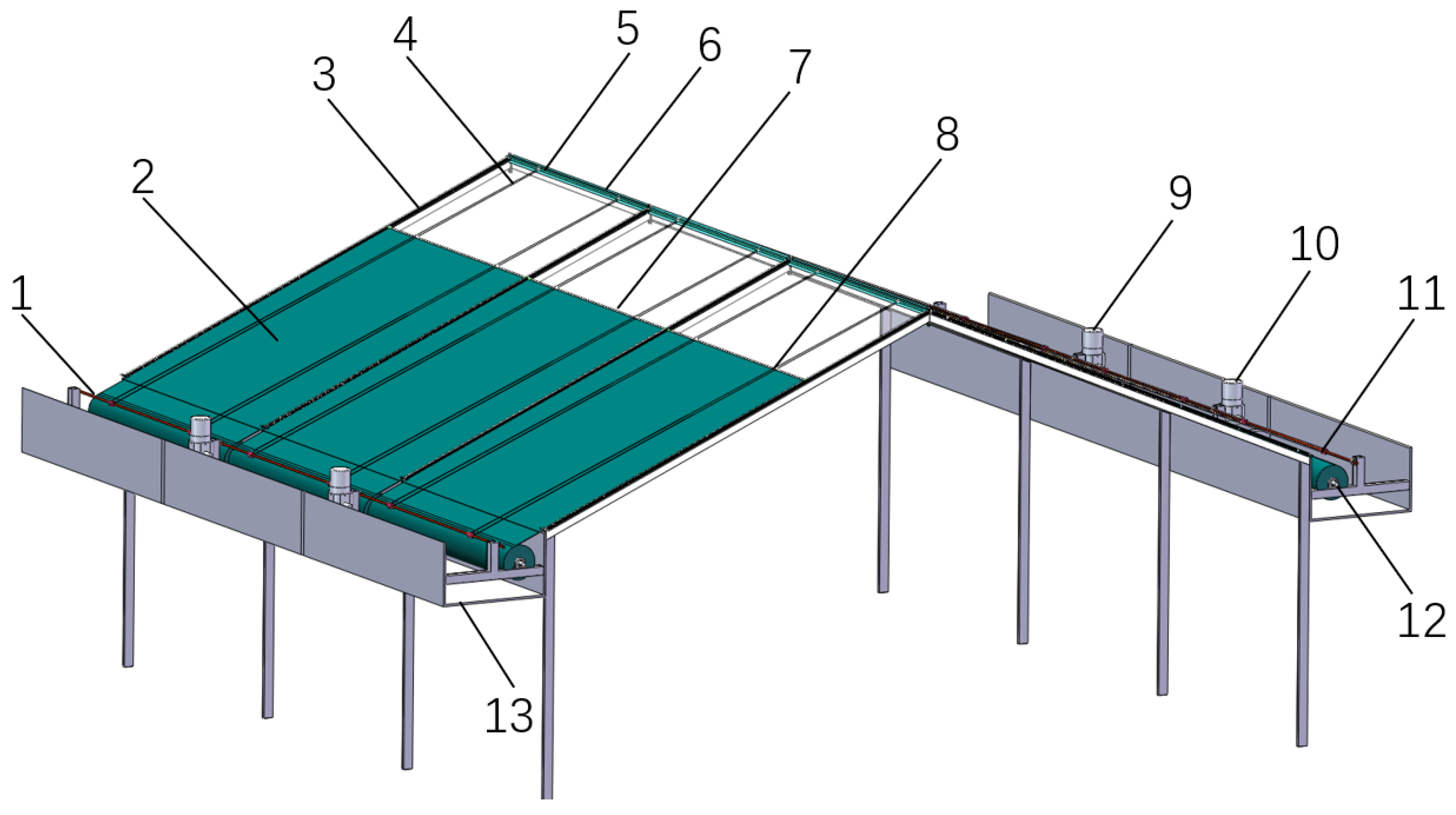
2.1. Overall Design and Working Method

An overall view of the EIS is shown in Figure 1. The guide rail was composed of a sealed track and bottom flaring fixed to the herringbone beam of the greenhouse roof. The external thermal blanket was embedded in the guide rail by wrapping soft nylon rope on both sides. The coil blanket shaft and the coil rope shaft were placed parallel in the gutter with bearing seat support and driven by their respective drive motors. The external thermal blanket was fixed on the coil blanket shaft at the bottom edge, and the coil blanket shaft was rolled up with the external thermal blanket and placed in the gutter. The drive rod was connected to the top edge of the external thermal blanket and drove the external thermal blanket to move on the greenhouse roof along the guide rail. A traction rope was fixed and connected to the drive rod through the drive clip. One end was wound in the thread groove of a coil bobbin on the coil rope shaft, and the other end was wound around the guide wheel in the top wind hood, thus making the traction rope form a closed-loop transmission.
The EISs were installed in the north–south direction according to the greenhouse trend, so that they could be used for insulation in winter and shading in summer. There are no internal insulation and shading structures that can effectively reduce the shading belt caused by the overlapping and intersecting shading and insulation structures installed east–west in Venlo-type multi-span greenhouses [28]. Moreover, the shading bands inside the greenhouse can move east–west in response to changes in the azimuth of the sun, ensuring an even distribution of light within the greenhouse. The working method of the EIS is illustrated in Figure 2. On winter mornings, as the sun rose from the east, to balance the greenhouse’s exposure to sunlight and coverage for insulation and to prevent abrupt changes in indoor temperature, the thermal blanket covering the east side of the greenhouse roof was first furled at 07:00–08:00. The east side of the greenhouse roof allowed light penetration, whereas the west side continued to be covered by a thermal blanket to reduce heat loss (Figure 2a). At 09:00, when the sunlight reached a certain angle, the thermal blanket on the west side was furled, allowing full light penetration through the entire roof (Figure 2b). In the afternoon, at 16:00–17:00, the EIS first covered the east side of the roof for insulation, whereas the west side continued to receive sunlight (Figure 2c). By 18:00, as the sun set, the thermal blanket covered the west side for insulation (Figure 2d). The EIS adjusted the furling and unfurling times of the thermal blankets on the east and west sides of the greenhouse roof according to seasonal weather changes. This modulation of light penetration and insulation was more conducive to the absorption and retention of heat in greenhouses, thereby enhancing the energy-saving efficiency.

2.2. Thermal Blanket

In the preliminary design phase, the material for the external thermal blanket of the multi-span glass greenhouse was determined by referencing and drawing upon the thermal blankets traditionally used in CSGs. The material comprised two layers of woven polyethylene (PE) fabric as the outer layer. It was lightweight, waterproof, abrasion-resistant, and had high tensile strength. It offered excellent weather resistance and protection for the middle insulating layer, with a final product weight of 220 g/m2. The middle insulation layer was composed of 8 mm polyethylene foam cotton combined with 200 g/m2 spray-bonded cotton, providing a soft, lightweight material with low thermal conductivity and good insulation properties. A thermal blanket can be joined by stitching or Velcro strapping. Considering the actual size of the greenhouse roof, each thermal blanket had a width of 3.8 m, a length of 6.8 m, and a unit area weight of 1200 g/m2.
Additionally, to ensure that the thermal blanket ran normally in the gutter and to determine the appropriate width of the gutter, we explored the relationship between the gutter width and the thickness of the thermal blanket. The thermal blanket was centered on the coil blanket shaft and rotated regularly with an Archimedes helix. The polar equation for the thermal blanket was as follows [29]:
R = R 0 + Δ 2 π θ
where R is the radius of the thermal blanket when rolled up, in mm; R 0 is the radius of the coil blanket shaft, in mm; ∆ is the thickness of the thermal blanket, in mm; and θ is the angle at which the coil blanket shaft is rotated about the polar origin, in rad.
By calculating the definite integral of the polar coordinate equation, the relationship between the thermal blanket radius, R, and the length of the thermal blanket when rolled up, L, can be obtained as follows:
L = 0 θ R d θ = 0 θ ( R 0 + Δ 2 π θ ) d θ
It was deduced that:
θ = 2 L R + R 0
Equation (3) was substituted into Equation (1) to obtain the relationship between the thickness of the thermal blanket, ∆, and the radius of the thermal blanket when rolled up, R:
Δ = ( R 2 R 0 2 ) π L .
The width of the gutter was set to D. Because two adjacent thermal blankets shared the same gutter, the following conditions must be satisfied for the thermal blanket to operate normally in the gutter:
D 4 R
In the experimental EIS, the thickness of the thermal blanket was 35 mm, the rolled-up length was 6200 mm, and the radius of the blanket roll shaft was 30 mm. From Equations (4) and (5), the minimum width of the gutter was Dmin = 1058.1 mm. The diameter of the rolled-up thermal blanket was 529 mm, with a maximum rolled-up diameter of 512.5 mm. Thus, a gutter width greater than 1058.1 mm would ensure that the two thermal blankets could be simultaneously rolled and placed in the gutter without additional shading. Considering the need to design and install a coil blanket shaft, coil rope shaft, and driving motor in the gutter, and to reserve sufficient space for the operation of the furling of the thermal blanket, the gutter width was designed to be 1600 mm. Based on this, the specific parameters of the related components of the traction rope transmission mechanism in the EIS were determined.

2.3. Critical Components Design

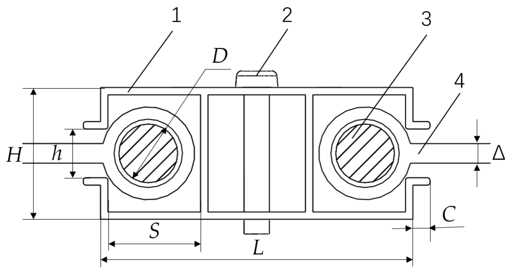
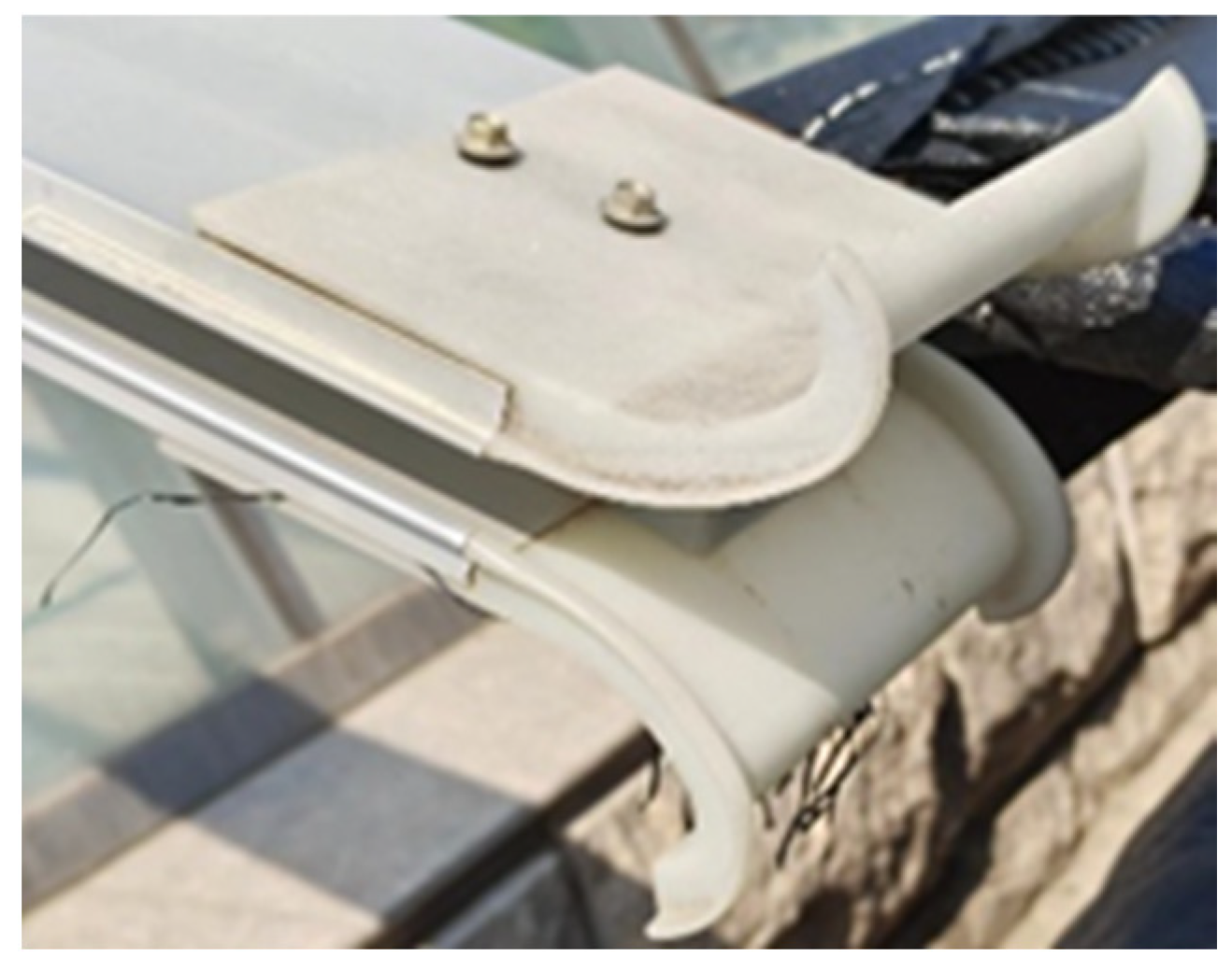
2.3.1. Seal Structure

Because the EIS was installed and operated on the outer roof of the greenhouse, considering the harsh environment outside the greenhouse and the unstable working conditions, the EIS needed to have excellent windproofing performance to ensure the stable operation of the system. In addition, after the EIS unfurled the thermal blankets, there were gaps between the two adjacent thermal blankets and the thermal blankets within the structural framework of the greenhouse, resulting in air convection in the gaps and a large amount of heat loss from the greenhouse. Therefore, enhancing the airtightness of the EIS is crucial for improving the thermal insulation performance of greenhouses and reducing their energy consumption.
The sealing structure consisted of a sealed insulation blanket, guide rails, and a top windproof cover, based on the sealing principle illustrated in Figure 3. To address the issues of airtightness and wind resistance along the sides of the insulation blanket, the edges of the blanket were wrapped around soft nylon ropes with diameters of 25 mm, which were then embedded in the guide rails. The guide rail had a double C-shaped cross-section with the structural parameters listed in Table 1. The inner cavity of the guide rail was 35 mm wide and 40 mm high, with an opening smaller than the diameter of the nylon rope at 16 mm, which ensured that the rope did not slip out of the guide rail and that the insulation blanket always slid along the rail. Additionally, a C-shaped windproof cover was installed at the top of the multi-span greenhouse roof. When the drive rod moved the insulation blanket to the top of the roof, it fit snugly into the top windproof cover, thereby achieving airtightness and wind resistance at the top edge of the insulation blanket.
In addition, a trumpet flare was set where the thermal blanket entered the bottom of the guide rail to ensure that the thermal blanket smoothly entered and left the guide rail. Owing to the irregular shape of the rail flaring, it was £D printed out of nylon. The actual object is shown in Figure 4.

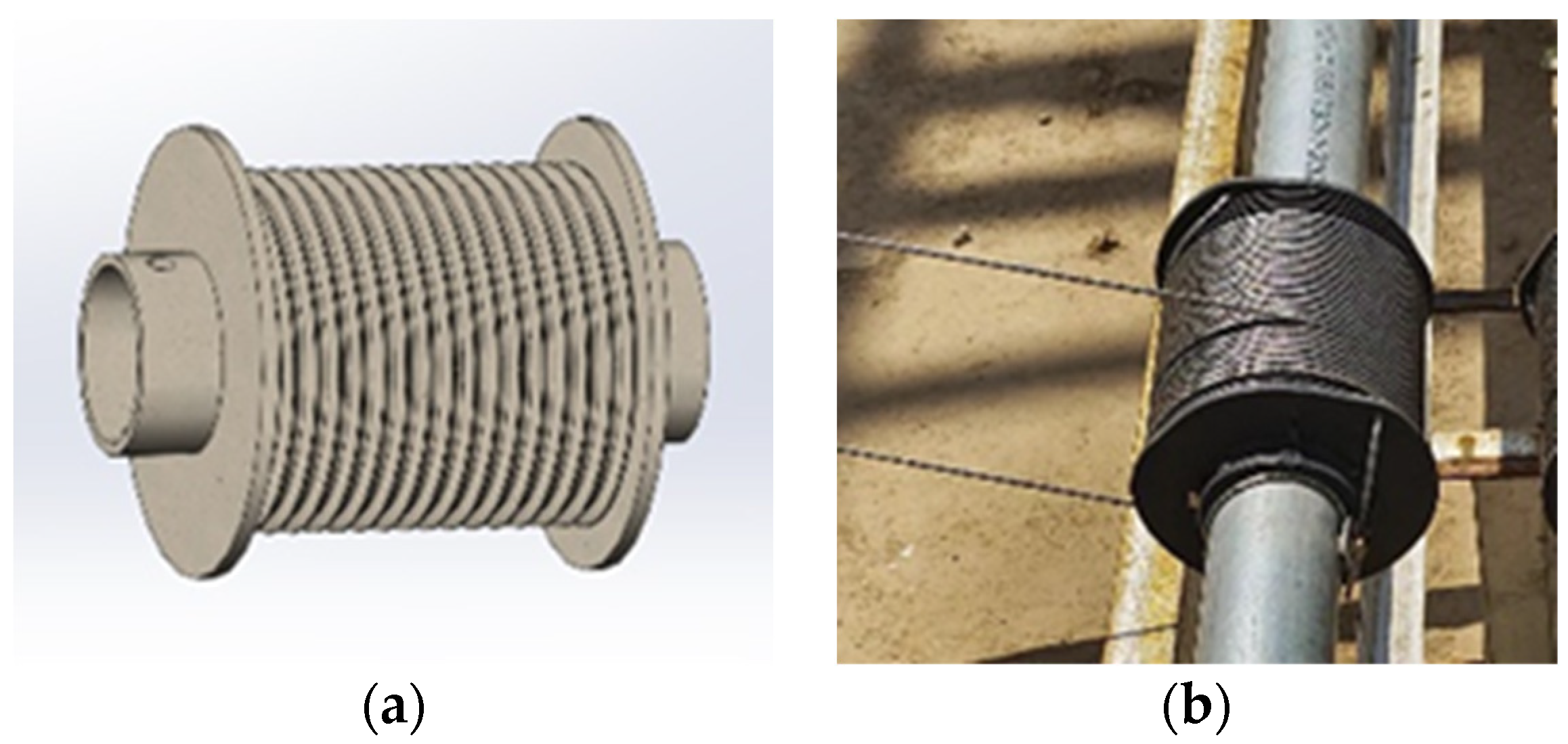
2.3.2. Traction Rope Transmission Mechanism

To meet the need for power transmission between the coil blanket shaft and the drive rod, and because the wire rope transmission has the advantages of simple structure, smooth transmission, long transmission distance, and high reliability and can work in a harsh outdoor environment [30,31], the stable operation of the system was achievable. The transmission mechanism mainly comprised a traction rope, guide wheel, drive rod, coil blanket shaft, and coil rope shaft. The structural parameters of the main components are listed in Table 2. In addition, a coil bobbin was placed on the coil rope shaft, as illustrated in Figure 5. Through the matching use of the coil bobbin and the wire rope, the wire rope can be wound on the coil bobbin in an orderly manner. It was not easy for these to overlap or deviate, which further ensured the stability and orderliness of the wire rope during transmission without deviating from the track. The structural parameters of the coil bobbin are listed in Table 2.
The working principle of the transmission mechanism was as follows. After turning on the drive motor on the coil rope shaft, the motor rotated anticlockwise to drive the coil rope shaft, so that the coil bobbin fixed on the coil rope shaft rotated simultaneously. The traction rope was gradually tightened and wound onto the coil bobbin, pulling the drive clips fixed on the drive rods, which then drove the thermal blankets to slide along the guide rails from the gutter to the top of the greenhouse roof to complete the process of covering the entire greenhouse glass roof with thermal blankets. When it was necessary to retract the thermal blankets, the drive motor on the coil blanket shaft was turned on, the motor rotated clockwise to drive the coil blanket shaft to rotate synchronously, the thermal blankets were gradually tightened and wound onto the coil blanket shaft, the drive rods were pulled from the top of the guide rail to the bottom of the guide rail, and the thermal blankets were rolled onto the coil blanket shaft in the gutter, thereby completing the furling process of the thermal blankets.

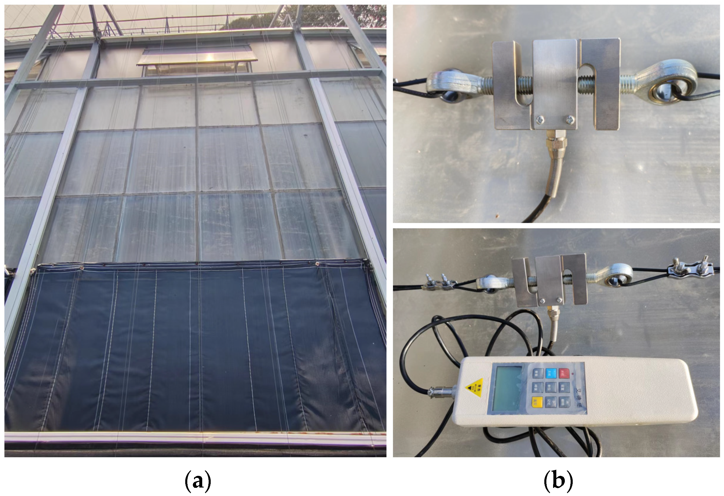
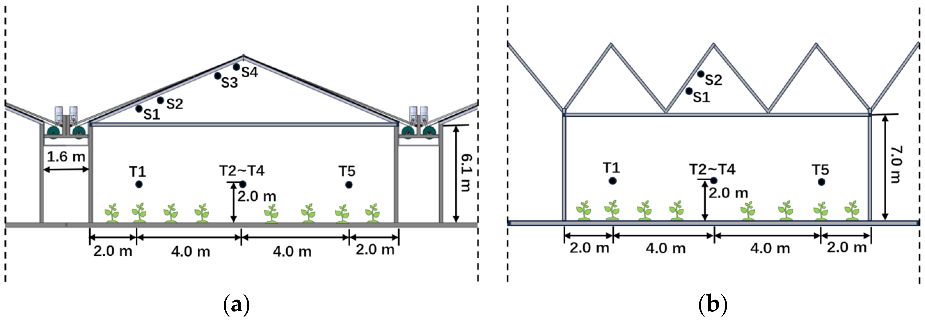
2.4. Experiment and Methods

To verify the feasibility of the working mode of the EIS, the reasonableness of the design of the components of the traction rope transmission mechanism, and the time taken to unfurl and furl the thermal blankets, a prototype of the EIS was built for the system verification test. The test prototype is shown in Figure 6a, and the test site was the Shouguang Smart Agriculture Science and Technology Park in Weifang, Shandong Province, China.
An S-type DYLY-103 tension sensor and an HP-2K digital tension meter were used to detect and record the tension of the traction rope in real time, with a measuring range of 2 KN and a data accuracy of ±0.1 N. The sensor and meter were set on the traction rope on the side of the thermal blanket. The test process involved first pulling the thermal blanket from the gutter to the set position on the top of the greenhouse roof through the driving motor and the traction rope transmission mechanism to achieve full coverage of the greenhouse roof. After the monitoring data were stable, the driving motor was reversed so that the thermal blanket was furled from the top of the roof to the gutter. The traction rope tension data were continuously monitored and collected throughout the process with a data collection interval of 4 s. The data were organized and analyzed using Microsoft Excel. Additionally, the actual time required by the EIS to furl and unfurl the insulation blanket was recorded. Figure 6b illustrates the installation of the tension sensors.
To verify the insulation performance of the EIS, an external insulation multi-span greenhouse (G1) installed with EISs was used, and a Venlo-type multi-span greenhouse (G2) equipped with double-layer internal insulation systems was used as a control. The experimental greenhouse (G1) was located in Shouguang Smart Agriculture Science and Technology Park, Weifang, Shandong Province, China. The greenhouse area was 8484.6 m2; the external thermal blankets covering the eastern roofs on G1 were furled between 07:30 and 08:00, the thermal blankets of the west roofs were furled between 08:00 and 09:00, and the external thermal blankets were unfurled between 16:30 and 17:00. The external thermal blankets were fitted closely to the greenhouse roof. When the indoor air temperature dropped to approximately 12 °C at night, an air source heat pump was used as the heat source, a surface air cooler was used for heat exchange to heat the air, and the heated air was sent into the greenhouse for heating by frequency conversion control using three groups of seven fans [32]. The opening period for the roof vent of G1 was from 09:00 to 10:00, with an approximate opening angle of 25°. The closing period was from 14:00 to 15:00. The control greenhouse (G2) was located in the town of Shouguang Vegetable, Shandong Province, China, approximately 11 km away from G1, and had an area of 3948 m2. G2 adopted automatic operation management. The double-layer internal thermal screens of the greenhouse were furled at 07:30 and unfurled between 17:00 and 17:30. The greenhouse used a natural gas boiler for pipeline heating, and the heating period was from 20:00 to 09:00 the next day. The heating duration was adjusted according to changes in the weather. The roof vent of G2 was open from 11:30 to 14:00, with an approximate opening angle of 25°. During the experimental testing period, both greenhouses cultivated tomatoes as the planted crop.
The thermal insulation performance of the greenhouses was tested from 29 November to 12 December 2022. The air temperature inside the greenhouses and the temperatures at the inlet and outlet of the fans were measured using a HOBO U14-001 temperature recorder (Onset Company, Bourne, MA, USA), with an accuracy of ±0.2 °C. The temperature sensors were placed at a height of 2 m from the ground in the center of the greenhouse. The outdoor temperature was measured using a HOBO U30 small automatic weather station (Onset Company), with a measuring accuracy of ±0.2 °C and a measuring range of −40~75 °C. The weather station was installed in the open area near the multi-span greenhouses. An HFP01SC heat flux sensor (Hukseflux Company, Delft, The Netherlands), was used to measure the heat flux on the roof and in the gutter of the greenhouse, with a sensitivity of 50 μV/W/m2 and a measuring range of −2000~2000 W/m2. The sensors were placed inside the glass roofs of the greenhouses. All sensor positions are illustrated in Figure 7.

3. Results

3.1. Traction Rope Tension

It can be seen from the test results that the coil ropes and coil blankets ran smoothly during the entire process of unfurling and furling the thermal blankets. The variation curve of the traction rope tension during the entire unfurling and furling processes is shown in Figure 8.
While unfurling the thermal blankets, the traction rope pulled the drive rod to drive the thermal blankets to slide along the guide rail to the top of the greenhouse roof to achieve coverage. At the beginning, owing to the start of the coil rope shaft motor, the traction rope tension reached the first peak value of 329.8 N, and then with the gradual increase in the unfurling length of the thermal blankets, the gravity of the thermal blanket needed to be balanced, and the friction between the thermal blanket and the glass roof also increased; thus, the traction rope tension gradually increased. Moreover, because the greenhouse roof was not entirely flat (due to the protrusion of an adjacent glass joint), the thermal blankets were wrinkled, their internal distribution was uneven, and the tension of the traction rope fluctuated [33]. When the drive rod drove the thermal blanket close to the top of the greenhouse roof, the traction rope tension reached a maximum value of 586.8 N, and the maximum tension of the wire rope, with a diameter of 2 mm, was 2296 N. Therefore, the wire rope met the required strength. When the thermal blankets were furled, the coil blanket shaft rotated and wound the thermal blankets, causing the traction rope to move passively with the drive rod. The tension of the traction rope rapidly decreased to a minimum value of 175 N. Subsequently, it increased slightly and fluctuated around 180 N until the thermal blanket was fully furled.

3.2. Operation Time

The average value obtained from three measurements was adopted for the actual unfurling and furling times of the thermal blankets for the prototype EIS. The specific results are shown in Table 3.
As shown in Table 3, the average unfurling time was 4.303 min, and the average furling time was 3.682 min. Therefore, it can be seen from the actual production that the EIS met the requirements of the current standard (NY/T 2205-2012, “Quality Evaluation Technical Specifications for Greenhouse Curtain Machines”) [34]. This specification mandates that the unfurling and furling times for thermal blankets installed in greenhouses with a span of 8 m or less (inclusive) should be between 3 min and 8 min [35].
The test demonstrated that the entire EIS operated smoothly and steadily and possessed good airtight and wind-resistant properties. The designed traction-rope transmission mechanism effectively furled and unfurled the thermal blanket. The tensile strength of the selected traction rope satisfied the maximum strength requirements of the test. The actual operational times for furling and unfurling the thermal blanket complied with the relevant technical specifications. The EIS fully covered the external roof of a multi-span greenhouse with thermal blankets.

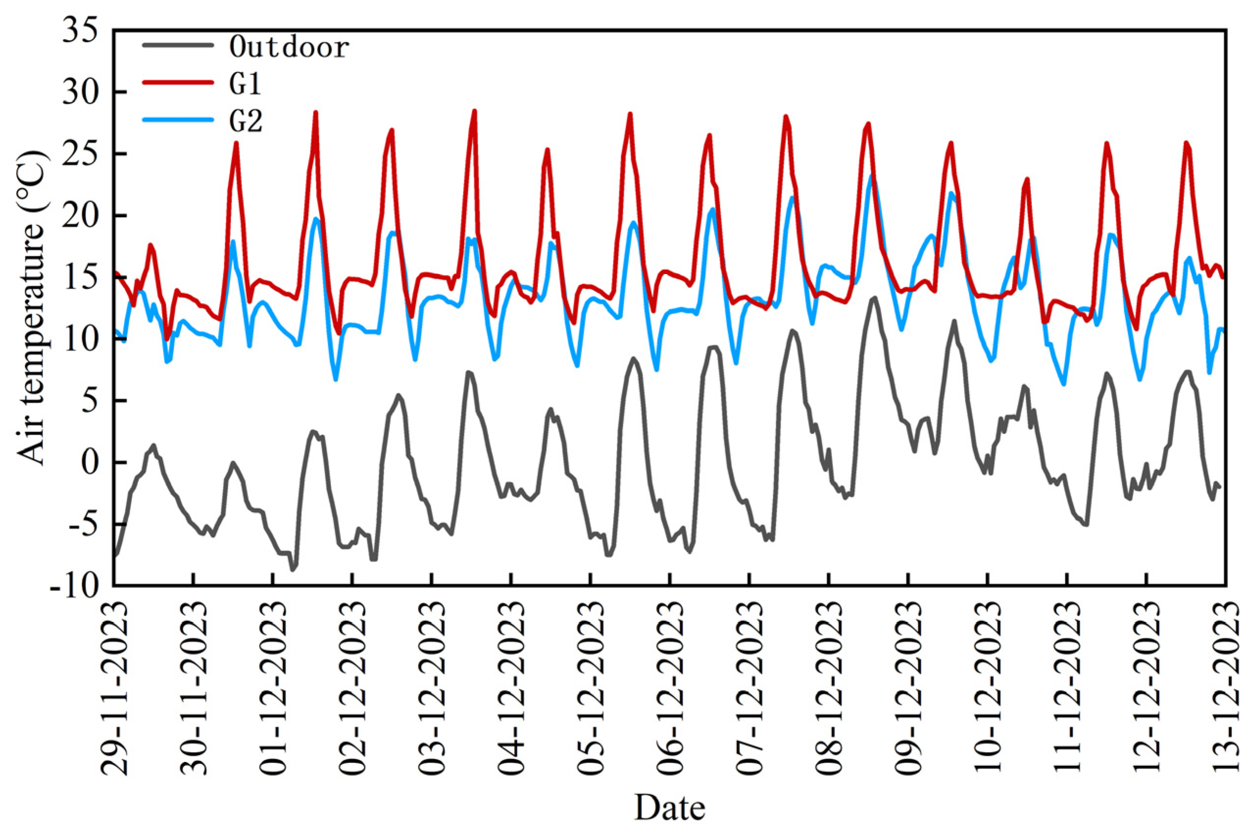
3.3. Greenhouse Air Temperature

3.3.1. Indoor Temperature Analysis

Over a continuous 14-day period, the hourly temperature changes in the greenhouse were recorded, as shown in Figure 9. During this period, the outdoor temperature ranged from −8.7 °C to 13.3 °C, with an average outdoor temperature of 0 °C. The temperatures in the externally insulated multi-span greenhouse (G1) and the Venlo-type multi-span greenhouse (G2) varied from 9.9 °C to 28.5 °C and 6.4 °C to 23.2 °C, respectively, with average temperatures of 16.2 °C for G1 and 13.4 °C for G2.
At night, G1 utilized its EIS to unfurl and cover the greenhouse roof with an external thermal blanket, resulting in an average nighttime temperature of 13.8 °C, which met the temperature requirements for nighttime greenhouse production. In G2, a double-layer internal insulation curtain was used at night, maintaining an average nighttime temperature of 12.6 °C. The average nighttime temperatures of the two greenhouses were not significantly different. However, the average temperatures during the day were 17.8 °C for G1 and 14.5 °C for G2. Although the insulation covers of both greenhouses were fully furled, and the greenhouses were sealed during the day, there was a notable difference in their average daytime temperatures. This can be attributed to the higher light transmittance of the externally insulated greenhouse, which allowed it to receive more solar radiation.

3.3.2. Typical Weather Temperature Changes

Figure 10a illustrates the temperature variation in a greenhouse on a typical sunny day. At 07:30, the thermal blankets on the east side of the roof were furled, resulting in an indoor temperature of 13.3 °C. Within 15 min, the temperature rose by 0.1 °C, without a sudden drop. This stability can be attributed to the unfurling of the thermal blankets on the western roof, allowing solar radiation to enter through the east side of the roof and minimize heat loss, thus achieving a net heat gain within the greenhouse. From 07:30 to 09:00, as the solar radiation gradually intensified, the indoor temperature steadily increased at a rate of 2.9 °C/h. At 09:00, when the western side’s thermal blankets were furled, the entire roof became exposed to solar radiation, raising the indoor temperature to 17.7 °C. The peak temperature of 28.5 °C was reached at 12:40. From 09:00 to 12:40, when the thermal blankets were completely furled, the rate of temperature increase remained consistent at 2.9 °C/h. At 16:30, the thermal blankets were unfurled, leading to a gradual decline in the indoor temperature, reaching its lowest at 12.3 °C by 20:00. During this interval (16:30 to 20:00), the rate of decrease in temperature in the external insulated multi-span greenhouse (G1) was 1.5 °C/h, compared to 2.0 °C/h in the Venlo-type greenhouse (G2), indicating that the EIS effectively decelerated the temperature decrease, thereby enhancing the greenhouse’s thermal insulation. By 20:00, with heating initiated, the indoor temperature gradually increased and stabilized at approximately 15 °C.
On a typical cloudy day (Figure 10b), at 07:30, G1 furled the thermal blankets on the east side of the roofs, and the indoor temperature of the greenhouse remained stable at 13.8 °C within 15 min, for the same reason as on a typical sunny day. From 08:00 to 09:30, the indoor temperature of G1 gradually increased, with a rate of increase of 2.0 °C/h, and a decrease in the indoor temperature occurred during this time period due to the fully furled double-layer inner insulation curtains of G2, with a rate of temperature decrease of 1.2 °C/h. At 09:30, G1 furled the thermal blankets on the west side of the roof. The indoor temperature reached a peak value of 23.0 °C at 12:00, and the temperature increased at a rate of 3.2 °C/h during the period from 09:30 to 12:00, which was faster than the temperature increase during the time when the thermal blankets were not fully furled. After that, the temperatures of the two greenhouses gradually converged and continued to decline. After heating was initiated, the temperature of G1 stabilized at approximately 13.0 °C, while the temperature of G2 gradually decreased until the greenhouse temperature reached a minimum of 6.4 °C at 22:00. At this time, the difference in temperature between the two greenhouses was 6.6 °C.

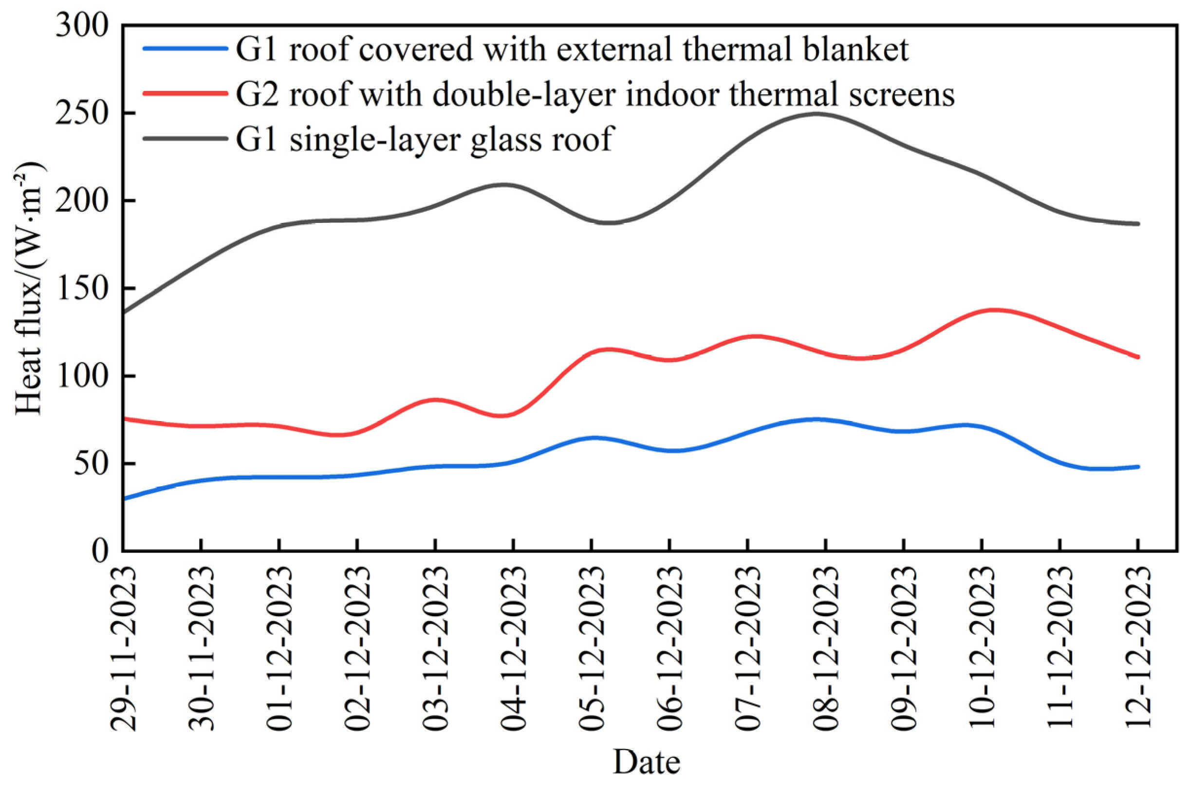
3.4. Heat Flux of the Greenhouse Roofs

Over a continuous 14-day period, the daily variation in the nighttime thermal flux of the greenhouse roof with external insulation was measured and analyzed, as shown in Figure 11. The daily range of roof thermal flux for greenhouses with external insulation was 30.0 to 75.1 W/m2, compared to 136.2 to 249.3 W/m2 for single-layer glass roofs. The average thermal fluxes during this period were 54.2 W/m2 and 198.6 W/m2, respectively, indicating that external insulation reduced heat loss through the glass roof by 72.7%. Meanwhile, greenhouses using double-layer internal insulation exhibited thermal flux ranging from 67.7 to 136.9 W/m2, with an average of 99.9 W/m2. The heat loss from roofs with external insulation was only 50.3% of that from roofs with internal insulation. Considering the negligible difference in the average nighttime temperatures between the two greenhouses, the externally insulated multi-span greenhouse in this study demonstrated superior insulation performance compared to traditional internally insulated continuous greenhouses. Fan et al. [12] reported an average heat input of 74.5 W/m2 over 30 d during the heating period in a Shouguang external insulation greenhouse, maintaining an average indoor–outdoor temperature difference of 17.4 °C, which is indicative of lower energy consumption. Furthermore, owing to the design flaws in the top windows of the external insulation greenhouse, which pose a risk to the movement of the thermal blanket, the actual coverage area of the external insulation during the experiment was approximately 60–80% of the roof area. It can be anticipated that, when the greenhouse’s external insulation fully covers the roof, the thermal insulation and energy-saving effects of a multi-span greenhouse equipped with EIS will be even more pronounced.

4. Conclusions

(1)
This study proposes an approach for the external insulation of the roofs of multi-span glass greenhouses, The EIS was designed and built to practice this approach. The system achieved full coverage of the greenhouse roof through the mechanized unfurling and furling of external thermal blankets, thereby achieving energy-saving thermal insulation. The experimental analysis shows that the EIS runs stably, and the insulation effect is remarkable.
(2)
This paper provides detailed design and structural parameters for critical components such as the traction rope transmission mechanism and the rail-type sealing structure. Through a system verification experiment, the specifications of the traction rope were determined. The maximum tension of the traction rope was 719.1 N, which is less than the minimum breaking strength of 2296 N for the selected 2 mm steel wire rope. The average unfurling time for the thermal blanket was 4.303 min, and the average furling time was 3.682 min, meeting the current performance requirements for the time required to furl and unfurl thermal blankets in greenhouses.
(3)
The insulation effect of the EIS was analyzed via an insulation performance experiment. The results indicate that the average temperatures in the external insulation multi-span greenhouse and the Venlo-type multi-span greenhouse were 13.8 °C and 12.6 °C over a continuous 14-day period, respectively. The average thermal flux of the greenhouse roof with external insulation was 54.2 W/m2, compared to 198.6 W/m2 for the single-layer glass roof, indicating a 72.7% reduction in heat loss through the glass roof with external insulation. During the same period, the average thermal flux of the double-layer internally insulated Venlo-type multi-span greenhouse was 99.9 W/m2. In comparison, the heat loss from roofs with external insulation was only 50.3% of the heat loss from roofs with internal insulation. On the basis of maintaining the required temperature for normal greenhouse production, the external insulation multi-span greenhouse demonstrates superior energy-saving thermal insulation effect.
(4)
The above research provides a new solution for energy-saving insulation in multi-span greenhouses, and the external thermal blankets used in EIS show favorable thermal insulation performance. However, the material that these thermal blankets are made out of is relatively thick and heavy, which imposes certain requirements on the load-bearing capacity of the roofs of multi-span greenhouses, increasing greenhouse construction costs. Further research could explore the adoption of lighter, thinnerandbetter thermal insulation performance materials to alleviate the load pressure on the greenhouse’s structure.

5. Patents

Wenzhong Guo, Bo Zhou, Dongdong Jia, Hong Chen, Weituo Sun, Fan Xu, Chao Shang, Youli Li—Performance of multi-span greenhouse structure with external insulation. Application Number: ZL 201910721585.9, China National Intellectual Property Administration.

Author Contributions

Conceptualization, W.G. (Wenzhong Guo), W.S., Q.Z. (Qian Zhao) and D.J.; methodology, W.G. (Wenzhong Guo) and W.G. (Wenfei Guan).; software, X.H.; validation, W.S. and H.W.; formal analysis, W.G. (Wenfei Guan); investigation, W.G. (Wenfei Guan) and F.C.; resources, H.W. and Q.Z. (Qingzhen Zhu); data curation, W.G. (Wenfei Guan) and F.C.; writing—original draft preparation, W.G. (Wenfei Guan); writing—review and editing, W.G. (Wenzhong Guo); visualization, W.G. (Wenfei Guan); supervision, W.G. (Wenzhong Guo), W.S., Q.Z. (Qian Zhao), D.J. and X.W.; project administration, W.G. (Wenzhong Guo) and X.W.; funding acquisition, W.G. (Wenzhong Guo). All authors have read and agreed to the published version of the manuscript.

Funding

This research was funded by Ningxia Hui Autonomous Region Key Research and Development Program (2023BCF01047), the Natural Science Foundation of Jiangsu Province (Grant No. BK20230548).

Institutional Review Board Statement

Not applicable.

Data Availability Statement

Data are contained within the article.

Conflicts of Interest

The authors declare no conflicts of interest.

References

  1. Ahamed, M.S.; Guo, H.; Tanino, K. Energy saving techniques for reducing the heating cost of conventional greenhouses. Biosyst. Eng. 2019, 178, 9–33. [Google Scholar] [CrossRef]
  2. van Beveren, P.J.M.; Bontsema, J.; van Straten, G.; Van Henten, E.J. Minimal heating and cooling in a modern rose greenhouse. Appl. Energy 2015, 137, 97–109. [Google Scholar] [CrossRef]
  3. van Beveren, P.J.M.; Bontsema, J.; van Straten, G.; van Henten, E.J. Optimal control of greenhouse climate using minimal energy and grower defined bounds. Appl. Energy 2015, 159, 509–519. [Google Scholar] [CrossRef]
  4. Cuce, E.; Harjunowibowo, D.; Cuce, P.M. Renewable and sustainable energy saving strategies for greenhouse systems: A comprehensive review. Renew. Sustain. Energy Rev. 2016, 64, 34–59. [Google Scholar] [CrossRef]
  5. Gupta, M.J.; Chandra, P. Effect of greenhouse design parameters on conservation of energy for greenhouse environmental control. Energy 2002, 27, 777–794. [Google Scholar] [CrossRef]
  6. Papadakis, G.; Briassoulis, D.; Scarascia Mugnozza, G.; Vox, G.; Feuilloley, P.; Stoffers, J.A. Review paper (SEdstructures and environment). J. Agric. Eng. Res. 2000, 77, 7e38. [Google Scholar] [CrossRef]
  7. Xue, F.; Zhang, Y.; Fu, Y.; Li, P.; Guo, S. Effect of Four Kinds of Thermal Insulation Quilts on the Thermal Insulaation of Ningxia Winter Solar Greenhouse. North. Hortic. 2019, 14, 66–72. [Google Scholar]
  8. Liu, H.; Lu, L.; Sun, D.; Liu, P.; Li, Y.; Li, T.; Liu, X. A Two-Factor Thermal Screen Control Strategy for Chinese Solar Greenhouses in High-Latitude Areas. Agronomy 2023, 13, 821. [Google Scholar] [CrossRef]
  9. Adesanya, M.A.; Na, W.; Rabiu, A.; Ogunlowo, Q.O.; Akpenpuun, T.D.; Rasheed, A.; Yoon, Y.; Lee, H. TRNSYS Simulation and Experimental Validation of Internal Temperature and Heating Demand in a Glass Greenhouse. Sustainability 2023, 14, 8283. [Google Scholar] [CrossRef]
  10. Cao, X.B.; Wang, S.X. Development and prospect of energy-saving technology of multi-span greenhouse in northern China. Modern Agric. Sci. Technol. 2014, 23, 212–213+218. [Google Scholar]
  11. Li, D.X.; Zhou, Z.C.; Yu, L.H.; Lan, L.B.; Li, X.G.; Li, L. Exploring the status quo and trend of smart greenhouse development. Vegetable 2019, 05, 12–17. [Google Scholar]
  12. Anifantis, A.S.; Colantoni, A.; Pascuzzi, S. Thermal energy assessment of a small scale photovoltaic, hydrogen and geothermal stand-alone system for greenhouse heating. Renew. Energy 2017, 103, 115–127. [Google Scholar] [CrossRef]
  13. Rorabaugh, P.; Jensen, M.; Giacomelli, G. Introduction to Controlled Environment Agriculture and Hydroponics; Controlled Environment Agriculture Center: Tucson, AZ, USA, 2002; pp. 1–130. [Google Scholar]
  14. Runkle, E.; Both, A. Greenhouse energy conservation strategies. Mich. State Univ. Ext. Bul. 2012, 1, 1–16. [Google Scholar]
  15. Kristinsson, J. The Energy-Producing Greenhouse. In Proceedings of the PLEA2006, the 23rd Conference on Passive and Low Energy Architecture, Geneva, Switzerland, 6–8 September 2006; pp. 6–8. [Google Scholar]
  16. Zhou, B.; Sun, W.; Guo, W.; Zhou, B.; Shi, L.; Li, G. Analysis and optimization of greenhouse gutter effect on radiation distribution inside multi-span greenhouses based on dynamic model. Trans. Chin. Soc. Agric. Mach. 2021, 52, 286–292. [Google Scholar]
  17. Hee, W.J.; Alghoul, M.A.; Bakhtyar, B.; Elayeb, O.; Shameri, M.A.; Alrubaih, M.S.; Sopian, K. The role of window glazing on daylighting and energy saving in buildings. Renew. Sustain. Energy Rev. 2015, 42, 323–343. [Google Scholar] [CrossRef]
  18. Frangi, P.; Piatti, R.; Amoroso, G. Evaluation of different screens for energy saving in the greenhouse. Acta Hortic. 2011, 893, 275–280. [Google Scholar] [CrossRef]
  19. Rasheed, A.; Lee, J.W.; Lee, H.W. Evaluation of Overall Heat Transfer Coefficient of Different Greenhouse Thermal Screens Using Building Energy Simulation. Prot. Hortic. Plant Fact. 2018, 27, 294–301. [Google Scholar] [CrossRef]
  20. Kim, H.K.; Kang, G.C.; Moon, J.P.; Lee, T.S.; Oh, S.S. Estimation of thermal performance and heat loss in plastic greenhouses with and without thermal curtains. Energies 2018, 11, 578. [Google Scholar] [CrossRef]
  21. Akpenpuun, T.D.; Na, W.H.; Ogunlowo, Q.O.; Rabiu, A.; Adesanya, M.A.; Addae, K.S.; Kim, H.T.; Lee, H.-W. Effect of glazing configuration as an energy-saving strategy in naturally ventilated greenhouses for strawberry (“Seolhyang” sp.) cultivation. J. Agric. Eng. 2021, 52, 1–8. [Google Scholar] [CrossRef]
  22. Rasheed, A.; Kwak, C.S.; Na, W.H.; Lee, J.W.; Kim, H.T.; Lee, H.W. Development of a Building Energy Simulation Model for Control of Multi-Span Greenhouse Microclimate. Agronomy 2020, 10, 1236. [Google Scholar] [CrossRef]
  23. Rasheed, A.; Kwak, C.S.; Kim, H.T.; Lee, H.W. Building Energy an Simulation Model for Analyzing Energy Saving Options of Multi-Span Greenhouses. Appl. Sci. 2019, 10, 6884. [Google Scholar] [CrossRef]
  24. Rabiu, A.; Adesanya, M.A.; Na, W.; Ogunlowo, Q.O.; Akpenpuun, T.D.; Kim, H.T.; Lee, H. Thermal performance and energy cost of Korean multispan greenhouse energy-saving screens. Energy 2023, 285, 129514. [Google Scholar] [CrossRef]
  25. Yao, X. Study on Thermal Insulation Performance and Energy-Saving Effect of Ultra-Low Energy Solar Greenhouse. Master’s Thesis, Taiyuan University of Technology, Taiyuan, China, 2011. [Google Scholar]
  26. Ge, Q. Research on the Properties of Agricultural Heal Preservation Quilt for Greenhouse. Master’s Thesis, Northwest A&F University, Xianyang, China, 2018. [Google Scholar]
  27. Li, J.Y.; Qin, H.; Ma, C.W. Requirements of greenhouse heat preservation quilt in gobi desert in Xinjiang. Xinjiang Agric. Sci. 2015, 52, 931–939. [Google Scholar]
  28. Chen, F.; Sun, W.T.; Yu, W.Y. Analyzing light and thermal environment and insulation performance of a multi-span greenhouse with external insulation. Trans. CSAE 2023, 39, 194–203. [Google Scholar]
  29. Zhan, Z.P.; Yang, Q.C.; Zhang, Y. Design and simulation test of an over-the-top rolling system for external insulation of arch-shaped greenhouse. J. China Agric. Univ. 2020, 25, 102–112. [Google Scholar]
  30. Yin, X.; Bowling, A.P. Dynamic performance limitations due to yielding in cable-driven robotic manipulators. J. Mech. Des. 2006, 128, 311–318. [Google Scholar] [CrossRef]
  31. Arikawa, K.; Hirose, S. Mechanical design of walking machines. Philos. Trans. Math. Phys. Eng. Sci. 2007, 365, 171–183. [Google Scholar] [CrossRef]
  32. Sun, W.; Wei, X.; Zhou, B.; Lu, C.; Guo, W. Greenhouse heating by energy transfer between greenhouses: System design and implementation. Appl. Energy 2022, 325, 119815. [Google Scholar] [CrossRef]
  33. Sun, H.; Teng, G.H.; Zhang, X.F. Design and test on real-time measurement system of mat foller workload for sunlight greenhouse. Trans. CSAE 2014, 30, 138–145. [Google Scholar]
  34. NY/T 2205-2012; Quality Evaluation Technical Specifications for Greenhouse Curtain Machines. National Agricultural Machinery Standardization Technical Committee: Beijing, China, 2012.
  35. Zhang, G.X.; Fu, Z.T.; Li, X.X. Design and experiment of rear fixed type rolling shutter device in solar greenhouse. Trans. Chin. Soc. Agric. Mach. 2016, 47, 299–308. [Google Scholar]
Figure 1. Overall view of the single-span external insulation system (EIS). 1. Coil rope shaft. 2. External thermal blanket. 3. Guide rail. 4. Traction rope. 5. Guide wheel. 6. Top wind hood. 7. Drive rod. 8. Drive clip. 9, 10. Drive motor. 11. Coil bobbin. 12. Coil blanket shaft. 13. Gutter.
Agriculture 14 00281 g001
Figure 2. Working mode of the EIS. (a) Thermal blankets on the eastern roof are furled; (b) thermal blankets are furled; (c) thermal blankets on the eastern roof are unfurled; (d) thermal blankets are unfurled.
Agriculture 14 00281 g002
Figure 3. Seal structure: 1. Guide rail. 2. Fixing bolt. 3. Nylon rope. 4. Thermal blanket.
Agriculture 14 00281 g003
Figure 4. Flared rail bottom.
Agriculture 14 00281 g004
Figure 5. Coil bobbin. (a) 3D model; (b) physical map.
Agriculture 14 00281 g005
Figure 6. EIS operation test. (a) Test prototype of the EIS; (b) tension sensor.
Agriculture 14 00281 g006
Figure 7. Dimension of a single span and sensor [S (heat flux), T (temperature)] positions in the experimental greenhouse. (a) External insulation multi-span greenhouse (G1); (b) Venlo-type multi-span greenhouse (G2).
Agriculture 14 00281 g007
Figure 8. Variation curve of traction rope tension.
Agriculture 14 00281 g008
Figure 9. Temperature variation of the greenhouse from 29 November to 12 December 2022.
Agriculture 14 00281 g009
Figure 10. Temperature variation of the greenhouse in typical weather. (a) Sunny day (5 December 2022); (b) cloudy day (10 December 2022).
Agriculture 14 00281 g010aAgriculture 14 00281 g010b
Figure 11. Daily variation in nighttime thermal flux of the greenhouse roof.
Agriculture 14 00281 g011
Table 1. Structural parameters of the seal.
ItemsParameters
Height of the guide rail, H (mm)40
Opening size of the guide rail, h (mm)16
Diameter of the nylon rope, D (mm)25
Width of the cavity of the guide rail, S (mm)42
Width of the guide rail, L (mm)150
Width of the guide rail opening edge, C (mm)4
Thickness of the thermal blanket at the guide rail, Δ (mm)15
Table 2. Structural parameters of the transmission mechanism.
ItemsParameters
Diameter of the wire rope (mm)3
Length of the wire rope (m)13.5
Outside diameter of the drive rod (mm)20
Wall thickness of the drive rod (mm)1.5
Outside diameter of the coil rope shaft (mm)58
Wall thickness of the coil rope shaft (mm)2
Outside diameter of the coil blanket shaft (mm)58
Wall thickness of the coil blanket shaft (mm)2
Thinnest wall thickness (mm)4
External diameter of the coil bobbin (mm)115
Screw pitch of the coil bobbin (mm)6
Thread turns of the coil bobbin27
Thread groove width (mm)4
Thread groove depth (mm)3
Locating hole diameter of the coil bobbin (mm)5
Table 3. Actual unfurling and furling times of the thermal blankets for the EIS.
Test NumberUnfurling Time of Thermal
Blankets/Min
Furling Time of Thermal
Blankets/Min
14.3533.59
24.2713.787
34.2853.665
Average value4.3033.682
Disclaimer/Publisher’s Note: The statements, opinions and data contained in all publications are solely those of the individual author(s) and contributor(s) and not of MDPI and/or the editor(s). MDPI and/or the editor(s) disclaim responsibility for any injury to people or property resulting from any ideas, methods, instructions or products referred to in the content.

