Article

Design and Experiment of a High-Clearance Mid-Tillage Weeder for Dryland Farming

1
College of Agricultural Engineering, Shanxi Agricultural University, Jinzhong 030801, China
2
State Key Laboratory of Sustainable Dryland Agriculture (In Preparation), Shanxi Agricultural University, Taiyuan 030031, China
3
Dryland Farm Machinery Key Technology and Equipment Key Laboratory of Shanxi Province, Jinzhong 030801, China
*
Author to whom correspondence should be addressed.
Agriculture 2024, 14(3), 435; https://doi.org/10.3390/agriculture14030435
Submission received: 31 January 2024 / Revised: 26 February 2024 / Accepted: 5 March 2024 / Published: 7 March 2024
(This article belongs to the Section Agricultural Technology)

Abstract

:
Mechanical weeding is an important technical means for organic and regenerative agricultural systems. Current weed control equipment has a variety of problems, such as difficulty adapting to high-stalk crops and poor operational quality. A high-clearance mid-tillage weeder (HMTW) has been developed to meet the mechanical weed control needs of high-stalk crops. The weeder mainly comprises a suspension device, a frame, parallel four-rod profiling mechanisms, weeding operation components, and depth-limiting soil-cutting devices. Based on the agronomic requirements of dryland flat planting, the overall structure of the HMTW was determined, and the weeding unit and flat shovel hoe were designed. Theoretical analysis was conducted on the depth stability of the HMTW, and an optimization mathematical model of the HMTW was established to further improve its tillage depth stability for agronomic requirements. The optimization objective was to minimize the deflection angle (∆β) of the profiling rod on a vertical plane, and the parameters of the parallel four-rod profiling mechanism were optimized. Based on the optimized structural parameters, a prototype of the HMTW was developed and evaluated. The test results show that the optimized HMTW exhibited a good weeding effect, and the tillage depth stability was within the design operating range. When the driving speed was 1.0 m/s and the tillage depth was 8 cm, the weed removal rate, seedling injury rate, seedling burial rate, and qualified rate of tillage depth were 90.8%, 3.2%, 4.1%, and 94%, respectively. The proposed HMTW successfully meets the weeding agronomic requirements of high-stalk crops for dryland farming, and the performance analysis and optimization models provide technical references for the design and development of such structures.

1. Introduction

Weed control during crop growth is an indispensable and effective measure to ensure stable and high yields [1,2,3]. Currently, chemical methods are mostly used for weed control worldwide [4,5]. Chemical weed control has the advantages of being fast, efficient, and low in cost, providing thorough removal [6]. However, it also brings a series of problems, such as changes in weed communities, increased resistance to pesticides, an expanded resistance spectrum, pollution in the soil, additional water, and atmospheric environment changes, as well as introducing pesticide residues into agricultural products [7,8]. Currently, chemical weed control does not meet the requirements of modern organic green agricultural production development [9]. Therefore, organic and renewable agricultural systems are becoming increasingly valued. However, due to the lack of chemical control measures, the types and density of weeds in organic farmlands are higher than in conventional farmlands [10]. Effectively controlling weeds on farmlands poses significant challenges to developing organic agriculture [11]. Compared with chemical methods, mechanical weeding does not pollute the environment; moreover, it loosens the soil, stores water, preserves moisture, increases soil temperature, and promotes crop seedling growth [12,13,14]. Therefore, mechanical weeding exhibits great application prospects in global dryland agricultural production [15,16].
In dryland organic agriculture production, the existing mechanical weeding equipment is mostly matched with ordinary tractors with low ground clearance, which can only meet the weeding needs of crops at low growth heights [17]. However, when high-stem crops, such as corn, sorghum, and buckwheat, grow to higher heights, there is a need for intercropping and weeding. At this time, developing a high-clearance mid-tillage weeder (HMTW) is particularly important. For the HMTW, the unit must have a high ground clearance to ensure the passability of field operations and a stable tillage depth, small coefficient of variation, good surface leveling, and strong soil loosening performance after tillage in order to meet the requirements of weeding agronomy for dryland high-stem crops [18]. The stability of the tillage depth directly affects the operational quality of the weeding machine, and its influencing factors include the structural parameters of the working components, the soil’s physical properties, the shape of the weeding shovel, and the operating speed [19,20,21]. Therefore, it is particularly important to solve the tillage depth stability problem of the weeding machine for high-stalk crops.
To improve the stability of the tillage depth in agricultural machinery operations, researchers have conducted extensive research, mainly on the structural layout of the unit, parameter optimization, and automatic monitoring of the control system for tillage depth [22,23]. In terms of the structural layout and parameter optimization of the operation unit, Ryan et al. [24] studied the operational balance of the land preparation machine for wheat stubble in the northwest of the United States and proposed that the distance between the tillage machinery and traction machinery should not be less than 1200 mm. Sun Songlin et al. [25] conducted a force analysis on the plow body from two parts, the soil insertion process and the normal cultivation process, and determined the effect of the angle between the plow body support surface and the ground plane on the stability of cultivation, while Qin Kuan et al. [26] analyzed the stability of the tillage depth of the compound tillage machine and optimized structural parameters, such as the traction angle, plow body configuration angle, and spiral rising angle of the rotary tillage blade. In terms of an automatic control system for the tillage depth, Pasi Suomi et al. [27] proposed a disc plow-type seeder operation depth automatic control system, which uses multiple sensors to monitor the angle and ground clearance height of the seeder operation, with the control system using standard communication protocol to send instructions to the auxiliary hydraulic valve of the tractor. Xia Junfang et al. [28] proposed a tillage depth monitoring method based on detecting the pitch angle of the vehicle body and the angle of the suspension lifting arm to address issues such as poor surface smoothness and an unstable tillage depth during cultivation. In summary, monitoring the depth of cultivation through sensors and real-time control of the cultivation depth by the control system with a high degree of automation is an important research area for the precise operation of cultivation machinery. However, the existing automatic control of cultivation depth has problems, such as insufficient system reliability and high costs [29]. Meanwhile, optimizing the structural layout parameters of the unit to enhance the stability of the tillage depth is a simple and reliable technical means with strong applicability and high stability. However, there is relatively little research on the theoretical analysis of the stability of tillage depth and the optimization of structural parameters for tillage and high-gap weeding machines.
The present work mainly focuses on the study of a high-clearance mid-tillage weeder (HMTW) for dryland farming, focusing on the influence of structural parameters of working components of the HMTW. The objective is to develop an intercropping and weeding machine that can adapt to different growth stages of tall-stem crops, and to provide technical references for the development of high-performance intercropping and weeding equipment.

2. Materials and Methods

2.1. Overall Structural Design

2.1.1. Agronomic Requirements for HMTW

In the growth stage of dryland farming crops, according to traditional farming techniques, it is generally necessary to use a hoe 3–4 times [30]. The first weeding occurs during the seedling stage of the crop, when the tillage depth is shallow, to avoid damage to the crop roots; the second weeding takes place before crop jointing, and the depth of the weeding should be controlled at 3–6 cm. The third weeding occurs after the rain during the jointing period, and the depth of the weeding should be controlled at 5–10 cm. Field measurement and analysis were conducted on the plant height and weeding depth of high-stalk crops, such as corn, sorghum, and buckwheat, at different growth stages in dryland farming. The operational requirements are shown in Table 1.
Based on comprehensive analyses, the agronomic requirements for weeding machines for high-stalk crops in flat planting dryland are as follows:
  • The unit must have a high ground clearance.
  • Have a good stability in tillage depth.
  • Meet the requirements of weeding technology: weeding rate ≥ 85%, seedling damage rate ≤ 5%, and seedling burial rate ≤ 5%.
  • Adjustable line spacing for operation.
  • Loose soil and a flat surface after cultivation.

2.1.2. Overall Structure and Working Principle

The structure of the HMTW is shown in Figure 1, which is mainly composed of a suspension device, a frame, parallel four-rod profiling mechanisms, chain transmission systems, a welding frame of individual units, weeding components, depth-limiting soil-cutting wheels, hydraulic motor, lift cylinders, and a hexagonal drive shaft.
During work, an HMTW operation unit comprises a suspension device and a matching 50-horsepower high-clearance tractor. The suspension device is connected to the frame through two lifting cylinders, which can achieve the lifting of the HMTW and complete the conversion of different working states. Under the joint action of two lifting cylinders, the frame is always balanced during operation. The weeding components and limited-depth soil wheels are fixedly connected to a welding frame, and a parallel four-rod profiling mechanism is used to form a single group of tillage operations with the frame. According to the operation line spacing requirements, four sets of single groups can be flexibly arranged.
The weeding components can adopt various structural forms, such as flat shovel, arrow shovel, horizontal rotation, and vertical rotation according to the operational requirements of different crops and periods. When using rotary tiller working components, the tractor hydraulic system drives the hydraulic motor to work, driving the hexagonal transmission shaft and transmitting every single group of working components through the chain transmission system to achieve rotary tiller weeding operation. When using flat shovel or arrow shovel components for intercropping and weeding, the depth of operation is adjusted by the height position of the limited depth soil-cutting wheel relative to the weeding components. And the weeding components are matched with a parallel four-rod mechanism to ensure the stability of tillage depth and the unchanged working angle of the weeding shovel in order to meet the quality requirements of intercropping and weeding operations.

2.1.3. Main Technical Parameters

The main technical parameters of the HMTW are shown in Table 2.

2.2. Key Component Design

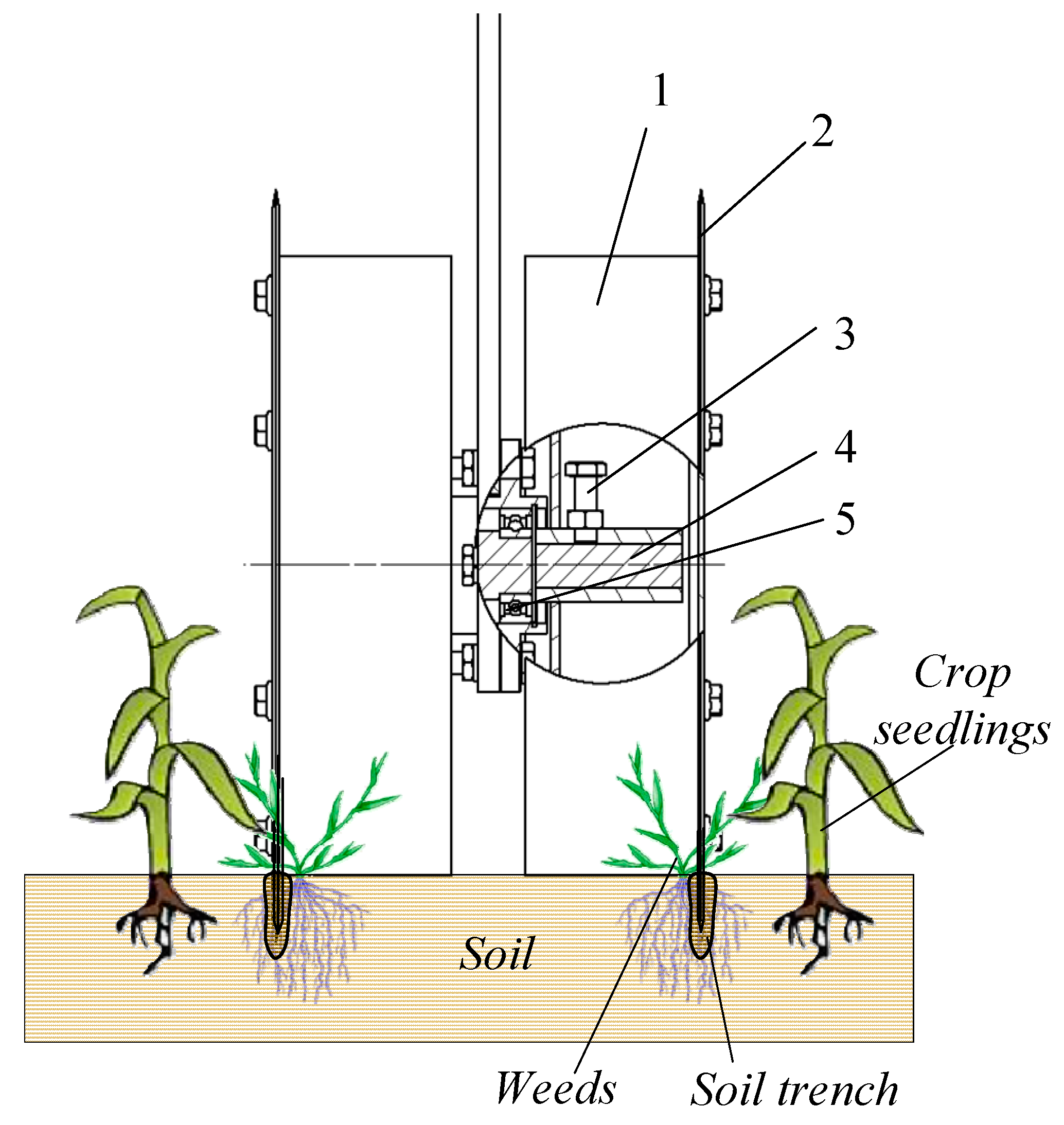
2.2.1. Design of Flat Shovel Weeding Components

  • Flat shovel hoe
The structure of a flat shovel hoe is shown in Figure 2, which is mainly composed of a shovel frame, shovel support, and shovel blade. The shovel frame is connected to the profiling single group frame to achieve power transmission. The shovel support forms a welded structure with the shovel frame, and the shovel blade is connected to the shovel support through countersunk screws.
In order to avoid soil blockage and reduce cutting resistance during the operation process, the normal direction of the blade edge is arranged at an acute angle with the direction of the operation speed (sliding cutting angle γ). The structural parameters of the flat shovel hoe: The cutting angle of the soil (δ), the width (w), and the thickness of the shovel support (s) affect the effectiveness of the shovel in cutting weeds, the height of the soil being lifted during operation, and the degree of soil fragmentation. When δ is large, it can cause the soil to move along the direction and on side of the hoe movement, forming small ditches and chaotic soil layers. When δ is small, it is necessary to increase the width w of the hoe. To ensure the effectiveness of weeding and avoid excessive soil displacement causing soil layers to become too chaotic, and taking into account the agricultural machinery design manual [31] and design experience, the cutting angle of the soil δ, the width w of the hoe, the thickness t of the shovel blade, and the thickness s of the shovel support are taken as 20°, 50 mm, 2 mm, and 8 mm, respectively.
When the soil block or weed being cut interacts with the blade edge, the force situation is shown in Figure 3, including the normal pressure N perpendicular to the blade direction, the frictional force Ff along the blade direction, and the resistance R opposite to the working direction v. According to the parallelogram rule, we should decompose N into the forward direction and the blade direction components, which are R and T, respectively. Considering the working requirements of sliding cutting and material backward movement, the force in the direction of the cutting edge should meet T > Ff [32], that is
N tan γ > N tan λ
In Formula (1): λ—the friction angle between the soil and the shovel blade, λ = 35°. It can be concluded that γ > λ.
Figure 3. Force situation of the shovel blade during operation.
Agriculture 14 00435 g003
For different types of soil cultivation, a different sliding cutting angle (γ) should be used. In sticky and wet soil, the friction angle between the soil and the shovel blade increases, and the angle should decrease. In sandy soil, the angle can increase [30]. In addition, in this design scheme, the angle γ can be freely adjusted. Therefore, taking γ = 35°–40°, The design results are shown in Table 3.
  • Configuration of the weeding shovel
The flat shovel hoe is arranged longitudinally within the row, as shown in Figure 4.
If the distance L of the current rear row weeding shovel is too small, it can easily cause soil blockage. Generally, L should meet the following conditions:
L H tan φ + λ + l 0
In Formula (2): H—tillage depth, 30–100 mm; l0—The extension of the hoe tip from the shovel handle, l0 = 164 mm; φ—Digging into the soil corner with a hoe, φ = 15°; λ—The friction angle between soil and shovel blade, taken as λ = 35°
According to Formula (2), it can be calculated that L ≥ 283 mm, taking L = 300 mm.
To avoid missing hoes during operation, there must be a certain overlap p in the width direction, which can be calculated using the following formula:
p = L tan α
In Equation (3), L—the distance between the front and rear rows of hoes and shovels; α—The deviation angle during the forward movement of the cultivator is 7° to 9° under normal operating conditions.
According to Formula (3), it can be calculated that p = 47.5 mm, taking p = 50 mm.

2.2.2. Design of Individual Weeding Units

  • Overall structure of individual weeding units
The overall structure of the weeding unit is shown in Figure 5, which mainly comprises a connecting frame, the profiling rods, a beam frame, a width adjustment device, a tillage depth adjustment device, a weeding component, and a depth-limiting soil-cutting wheel.
The weeding unit is installed on the crossbeam of the frame through a connecting frame, which can achieve row spacing adjustment. The width adjustment device and tillage depth adjustment device adopt a telescopic sleeve structure with a top screw positioning connection, which can achieve stepless adjustment. The weeding components and the depth-limiting soil-cutting wheel are fixedly connected to a beam frame. The beam frame forms a parallel four-rod profiling mechanism with the connecting frame through two profiling rods, ensuring the stability of the working depth. The main parameters and adjustment range of individual weeding units are shown in Table 4.
  • Structural design of depth-limiting soil-cutting device
In the seedling stage of crops, the root system is not fully developed, and when the weeding shovel cuts the soil, it is easy to cause damage to the seedlings. Considering the adaptability of the HMTW in weeding operations during the seedling stage, a depth-limiting soil-cutting device was designed. As shown in Figure 6, the depth-limiting soil-cutting device mainly comprises two sides of wheel rims, soil-cutting discs, a width adjustment mechanism, half shaft, bearings, and other components. The wheel rims, soil-cutting discs, and other components can rotate around the half shaft, while the working width can be freely adjusted according to the needs of weeding.
The depth-limiting soil-cutting device cooperates with a single profiling mechanism to limit the tillage depth and improve the hoe’s plowing depth stability. In addition, the soil-cutting discs on both sides cut open and break through the compacted soil to avoid lifting up compacted soil by the hoe-cutting soil, which often causes damage to seedlings. At the same time, they cut off the lateral roots of weeds and disrupt the lateral connection of the weeds’ roots and soil to avoid pulling out seedlings during weeding and breaking the soil.

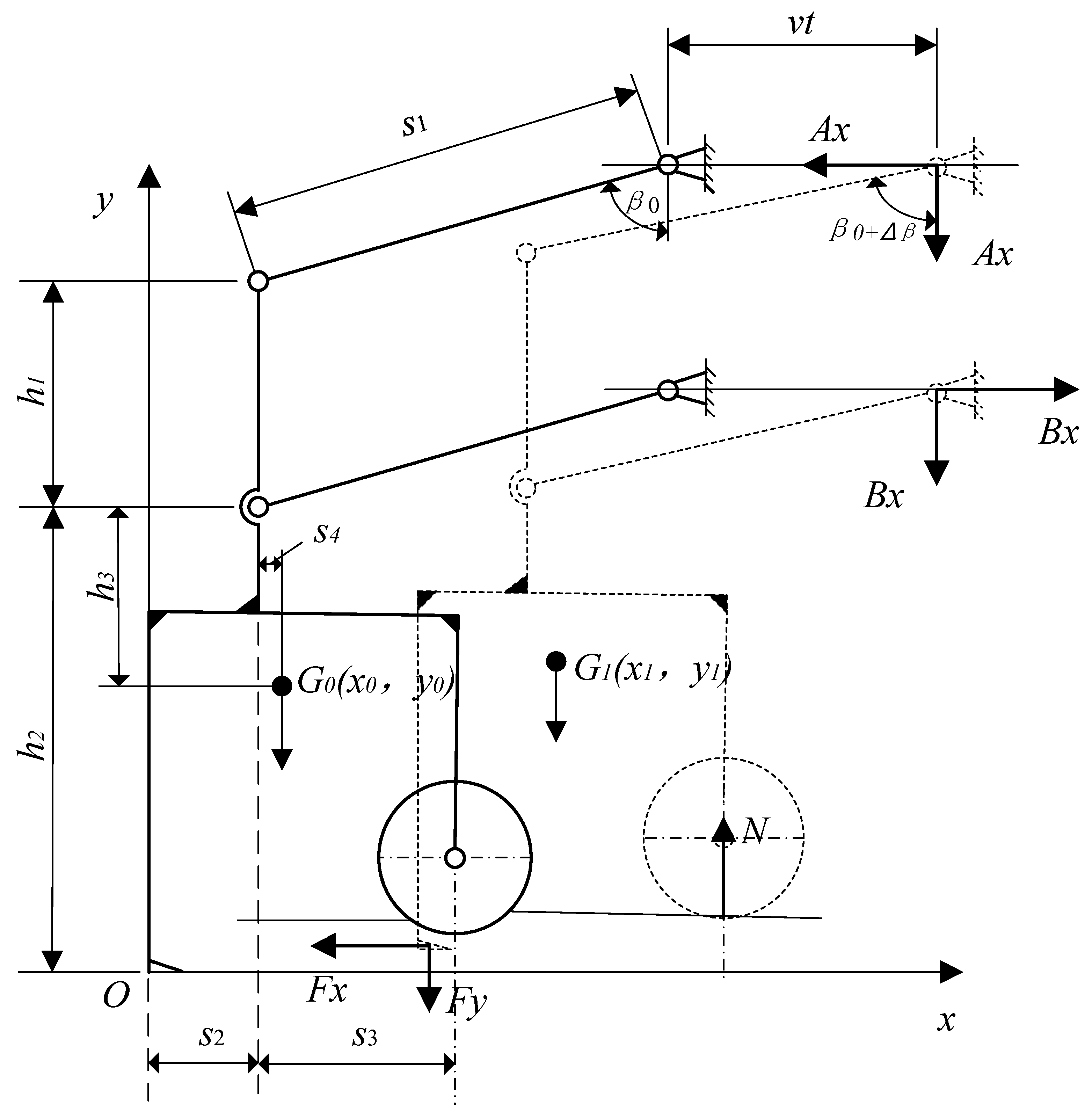
2.3. Optimization Design of Four-Rod Profiling Mechanism

The stability of the tillage depth of the working components of the HMTW directly affects its walking stability and operational quality. The stability of tillage depth is related to the balance of forces acting on the working components of the tiller and the structural parameters of the weeding unit. To improve the stability of the working components of the HMTW, it is necessary to analyze the relevant factors of the stability of the tillage depth and optimize the design of the weeding unit.

2.3.1. Theoretical Analysis of the Stability of Tillage Depth for Individual Weeding Units

The weeding components are connected to the frame through a parallel four-rod profiling mechanism; the structural parameters of each member and the force situation of the weeding working components are shown in Figure 7. A Cartesian coordinate system x-y with the center point O of the hoe action as the coordinate origin and the forward direction of the unit as the x-axis direction is established. For the convenience of calculation, we merged the two weeding shovels of the individual weeding unit.
If the center of gravity G of the weeding unit is represented by G0 (x0, y0) at the moment of starting motion, then
x 0 = s 2 + s 4 y 0 = h 2 h 3
In Equation (4), s2 is the horizontal distance between the hoe and the individual beam frame, s4 is the horizontal distance between the center of gravity of the weeding unit and the hinge point of the individual beam frame, h2 is the vertical distance between the lower hinge point of the individual beam frame and the hoe, and h3 is the vertical distance between the center of gravity of the weeding unit and the lower hinge point of the individual beam frame.
The HMTW moves uniformly along the O-x axis at a speed of v with a displacement of v t. The forces acting on the weeding unit include soil resistance Fx and Fy, the gravity of the weeding unit mg, the reaction forces Ax, Ay, Bx, and By at the hinge point, and the support reaction force N acting on the depth-limiting wheel. Assuming that the weeding unit produces an angular displacement ∆β under the disturbance torque MB, β0 is the initial angle of the profiling rod relative to the O-x axis. At this time, the center of gravity of the working component moves to the position of G1 (x1, y1), and then
x 1 = v t + s 2 + s 4 + s 1 sin β 0 s 1 sin β 0 + Δ β y 1 = h 2 h 3 + s 1 cos β 0 s 1 cos β 0 + Δ β
At this point, the speed at which the center of gravity moves is
x ˙ 1 = v s 1 Δ β ˙ cos β 0 + Δ β y ˙ 1 = s 1 Δ β ˙ sin β 0 + Δ β
When the driving speed v is constant, the system only has one degree of freedom. Using the angular displacement ∆β of the profiling rod as a common coordinate, we can determine the function of angle ∆β over time and use Lagrange’s second equation to establish a differential equation for the motion of weeding components:
d d x T Δ β ˙ T Δ β = Q β
In Equation (7): T—kinetic energy of the system; Qβ—generalized force.
The equation for system kinetic energy is
T = 1 2 m ( x ˙ 1 2 + y ˙ 1 2 )
In Equation (8): m—mass of the system.
Equation (8) can be transformed as follows:
T = 1 2 m v 2 2 v s 1 Δ β ˙ cos β 0 + Δ β + s 1 2 Δ β ˙ 2
Then,
T Δ β = 1 2 m 2 v s 1 Δ β ˙ sin β 0 + Δ β
T Δ β ˙ = 1 2 m 2 v s 1 cos β 0 + Δ β + 2 s 1 2 Δ β ˙
d d t T Δ β ˙ = m v s 1 sin β 0 + Δ β Δ β ˙ + s 1 2 Δ β ¨
According to Equations (10)–(12), Equation (7) can be rewritten as
m s 1 2 Δ β ¨ = Q β
To determine the generalized force Qβ, it can be written as the virtual work equation of the force acting on the working component:
M R δ Δ β = Q β δ Δ β
Therefore,
M R = Q β
In Equation (14): MR—the disturbance torque of the force acting on the weeding unit to the fixed point B on the frame.
As shown in Figure 7, the disturbance torque MR is
M R = A x h 1 F x h 2 + s 1 cos ( β 0 + Δ β ) + F y s 2 + s 1 sin β 0 + Δ β + m g s 1 sin β 0 + Δ β s 4 N s 1 sin β 0 + Δ β s 3
After transformation, Equation (15) can be written as
M R = F x s 1 cos β 0 + F y s 1 sin β 0 + m g s 1 sin β 0 N s 1 sin β 0 cos Δ β             F x s 1 sin β 0 F y s 1 cos β 0 m g s 1 cos β 0 + N s 1 cos β 0 sin Δ β +             A x h 1 + N s 3 F x h 2 + F y s 2 m g s 4
To facilitate calculations, set
a = F x s 1 cos β 0 + F y s 1 sin β 0 + m g s 1 sin β 0 N s 1 sin β 0 b = F x s 1 sin β 0 F y s 1 cos β 0 m g s 1 cos β 0 + N s 1 cos β 0 c = A x h 1 + N s 3 F x h 2 + F y s 2 m g s 4
The Lagrange Equation (10) can be rewritten as
m s 1 2 Δ β ¨ = a cos Δ β b sin Δ β + c
By performing first-order integration on Equation (17), we can obtain
Δ β ˙ 2 = 2 m s 1 2 a sin Δ β + b cos Δ β + c Δ β + d
In Equation (18): d—integral constant.
Because when t = 0, Δ β = 0 and Δ β ˙ = 0 , then d = b .
Equation (18) can be rewritten as
Δ β ˙ 2 = 2 m s 1 2 a sin Δ β + b cos Δ β + c Δ β b
Under the above conditions, it is advisable to
sin Δ β Δ β and   cos Δ β 1 Δ β 2 2
Equation (19) can be rewritten as
Δ β ˙ 2 = 2 m s 1 2 a Δ β + b 1 Δ β 2 2 + c Δ β b
or
Δ β ˙ = b m s 1 2 2 a + c b Δ β Δ β 2

2.3.2. Optimization Design of Parallel Four-Rod Mechanism

  • Objective function
When the HMTW is in operation, the soil resistance Fx, Fy, and N experienced by the weeding shovel vary over a large range. Therefore, the balance of forces acting on the weeding unit is periodically disrupted, causing the tillage depth of the weeding shovel to sway in the vertical plane. The deflection characteristic can be reflected by the deflection angle ∆β of the profiling rod. When the ∆β angle is maximum, Δ β ˙ = 0 ; therefore, Equation (20) can be rewritten as
2 a + c b Δ β Δ β 2 = 0
Namely,
Δ β = 2 a + c b
Substitute a, b, and c into Equation (21):
Δ β = 2 ( F x s 1 cos β 0 + F y s 1 sin β 0 + m g s 1 sin β 0 N s 1 sin β 0 + A x h 1 + N s 3 F x h 2 + F y s 2 m g s 4 ) F x s 1 sin β 0 F y s 1 cos β 0 m g s 1 cos β 0 + N s 1 cos β 0
The objective function for optimizing design is to minimize Δβ.
2.
Input parameter
At the moment when the hoe starts to excavate upwards, the soil resistance F received reaches its maximum value, and the total soil resistance F can be calculated by the following equation [31]:
F = i σ S
In Equation (23): i—number of weeding shovels; σ—soil shear resistance, taken as 1N/cm2, S—shear area (cm2).
S = h B sin γ
In Equation (24): B—working width of the shovel, 40 cm; γ—hoe blade angle, 40°; H—tillage depth, take 8 cm.
According to Equations (23) and (24), the total soil resistance F = 497.8N, and the relationship between the horizontal component Fx and the vertical component Fy can be expressed as follows [31]:
F x = k F y
In Formula (25): k = tan φ, φ—the total soil resistance and the inclination angle of the horizontal plane. Based on the working conditions and blade condition of the weeding shovel, φ = 20°, which means k = 0.36.
The reaction force N of the depth-limiting wheel support can be calculated by the following equation:
N = g m + m s + F 2
In Equation (26), ms—the mass of soil on the weeding shovel at the moment when the weeding component begins to rise.
m s = i S p h d s
In Equation (27), Sp—the projected area of the weeding shovel on the horizontal plane (cm2); ds—Soil volumetric density, taken as 0.0025 kg/cm ³
According to Equations (23)–(27), the input parameter values are shown in Table 5.
3.
Design variable
Design variables include: h1, h2, s1, s2, s3, s4, and β0.
4.
Constraint condition
By analyzing the structural parameters of the high clearance tractor and weeder frame, the dimensional boundaries of h1, h2, s1, s2, s3, and s4 are determined as follows:
200 h 1 400 450 h 2 800 200 s 1 600 0 s 2 200 0 s 3 200 200 s 4 200
To ensure the profiling effect of individual weeding operations and the arrangement of the lifting and limiting devices of the HMTW, the performance constraints are as follows:
h 1 + h 2 1000 s 2 + s 3 400 80 ° β 0 90 °
Using Equations (28) and (29) as constraints for optimizing models.
5.
Optimal Results
Using the fmincon function provided by MATLAB software (https://www.mathworks.com/products/matlab.html, accessed on 26 February 2024) to program and solve, the optimized parameters of each variable after rounding are shown in Table 6.

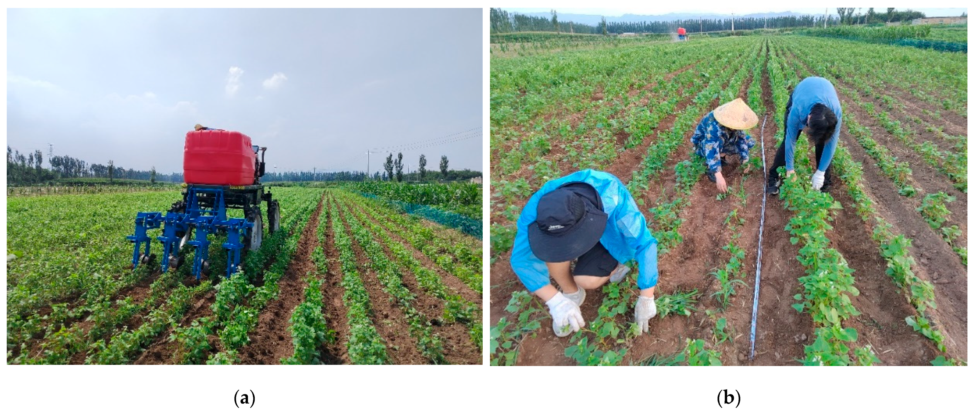
2.4. Field Performance Test

2.4.1. Prototype Trial Production

Design the structure of the HMTW based on optimized parameters and manufacture its physical prototype. As shown in Figure 8, it is an operation unit composed of a HMTW and a high-clearance tractor. The power is 36 kW, and it is equipped with a Beidou navigation auto-drive system and a real-time monitoring system for operation images.

2.4.2. Test Site Conditions

On 2 August 2023, a field weeding performance experiment was conducted in the Shenfeng experimental field of Shanxi Agricultural University in the Taigu District, Jinzhong City, Shanxi Province, China. The experimental crop in the field was sweet buckwheat, which was planted evenly with a width of 10 cm and a row spacing of 50 cm. The average seedling height is 48 cm, and the main weed is barnyard grass, with an average height of 12 cm. The soil moisture content in the field is 13.3%, the soil compaction is 0.34 MPa, and wheat residues and stems can be seen on the surface.

2.4.3. Test Methods

The experiment was conducted following the relevant provisions of DB63/T 1289-2014 “Operation Quality of Intertillage and Weeding Machines”.
  • Determination of measurement area
Starting from the edge of the field, reserve 20 m along the direction of crop rows as the starting acceleration zone, and then set every 10 m as a measuring area; that is, each measuring area is 10 m long × width of 2 m.
  • Determination of weeding rate
Randomly select 5 measurement points (length—1 m; width—2 m) within the measurement area of two round-trips and measure the number of weeds removed and the number of weeds not removed. The formula for calculating the weeding rate is as follows:
M c = n 1 n 1 + n 2 × 100 %
In Formula (30): Mc—weeding rate; n1—number of weeds removed; n2—number of weeds not removed.
  • Determination of seedling injury rate and burial rate
Injured seedlings refer to buckwheat seedlings damaged or pulled out during weeding operations. Randomly select 5 measuring points, each measuring point with a length of 10 m, and measure their total number of seedlings, number of injured seedlings, and buried seedlings, respectively. The formula for calculating the injured seedling rate is as follows:
S m = n s n × 100 %
In Formula (31): Sm—seedling injury rate; ns—number of undamaged seedlings; n—total number of seedlings.
The calculation formula for seedling burial rate is as follows:
M m = n m n × 100 %
In Formula (32): Mm—seedling injury rate; nm—number of undamaged seedlings; n—total number of seedlings.
  • Inspection of the qualified rate of tillage depth and the rate of broken soil in the plow layer
Randomly select 5 rows for testing. Measure 1 point each 1 m along the direction of the unit, and then measure 10 points on the left and right sides of each row. The vertical distance between the surface and the bottom of the cultivated layer is the plowing depth. The ratio of the qualified number of tillage depth measurement points to the total number of tillage depth measurement points, and this is recorded as the tillage depth qualification rate.
Measure all the topsoil blocks on the 1 m long operation width. Select the soil block with the longest side less than 4 cm and weigh it, denoted as ma. Weigh the mass of all the topsoil blocks on the 1 m long operation width, denoted as mb. Randomly select 20 points, calculate their soil fragmentation rate, and calculate the average value. The soil fragmentation rate is calculated using the following formula:
E i = m a m b × 100 %
E = E i n
In Formulas (33) and (34): Ei—the rate of soil fragmentation at random points; E—average value of soil fragmentation rate; N—Number of detection points.

2.4.4. Experimental Design

To explore the influence of weed removal machine operation parameters on weed removal efficiency and verify the cultivation stability effect of the optimized HMTW under different operating parameters, conduct a two-factor experiment in a completely sequential design, with the experimental factors being tillage depth and operating speed. The tillage depth is set at two levels, 5 cm and 8 cm, and the operating speed is set at four levels of 0.54, 1, 1.4, and 1.8. Repeat the experiment three times for a total of 24 experimental units. The weed control rate, seedling injury rate, and seedling burial rate can be used as experimental indicators for weed control effectiveness. The average plowing depth, qualified rate of plowing depth, and broken soil rate of the plow layer after the operation of the weeding machine can best reflect the stability of the machine farming and are, therefore, used as stability indicators for the operation.

3. Results and Discussion

3.1. Field Performance Test Results and Analysis

The field performance test scenario is shown in Figure 9.
The field test results of the HMTW have been compiled, and the average of the experimental results is listed in Table 7.
From the results of the weed control performance test, it can be seen that
(1)
The HMTW has a good weeding effect and operational stability within the designed operating range. At different operating speeds, the actual plowing depth remains stable at the set value, and the qualified rate of the plowing depth is higher than the relevant standard requirements (≥85%). The optimized weeding mechanism has a good effect on stabilizing the plowing depth.
(2)
Improving the driving speed has little impact on the weed control rate. This is because the experimental soil is sandy and relatively loose after rain. The flat shovel hoe has a better cutting effect. Although weeds with shallower roots are more easily removed when the operating speed increases, the leakage caused by deviation from the centerline also increases.
(3)
As the speed of driving increases, the rate of damaged seedlings and buried seedlings also increases. The increase in the seedling injury rate is because, as the unit’s operating speed increases, it becomes more difficult for the operator to drive along the line, causing the equipment to deviate from the centerline between the rows. The increase in the seedling burial rate is mainly due to the large wheat residue in the previous crop, which forms aggregates within the soil. After the operation speed is increased, the amount of soil displacement is large, which can easily lead to congestion of the working parts.

3.2. Stability Performance Analysis of Tillage Depth

By inputting the optimized parameters into Equation (23), the relationship between the structure parameters (h1, h2, s1, and β0) and the deviation angle ∆β can be obtained, as shown in Figure 10.
From the figure, it can be seen that, as the longitudinal dimensions, h1 and h2, of the weeding unit increase, the deflection angle ∆β of the profiling rod increases, which indicates that the ground clearance of the unit has a significant impact on the stability of the tillage depth. This result confirms the necessity of optimizing the stability of the tillage depth in the HMTW. When the length s1 of the profiling rod or the initial angle of the profiling rod β0 increases, the deflection angle ∆β of the profiling rod decreases. This indicates that increasing the length of the profiling rod helps to improve the stability of the tillage depth of the HMTW, which is also consistent with the actual working conditions, confirming that the established mathematical model is reliable.

3.3. Discussion

Most of the existing weed control equipment only meets the weed control needs of the seedling stage when the height of the crop is relatively low. However, some high-stem crops still require intermediate tillage and weed control when they reach a certain height. At this time, when a regular tractor passes through the crop row, the crop bends under the tractor, causing damage. C. Cordill et al. [33] cut off the top of the corn plant at a height of 250 mm to allow for undisturbed passage under the tractor in order to conduct weeding experiments on the developed weeding machine when the corn reached its growth stage. This approach increases the workload and can easily cause harm to crops. High-gap weeding machines can meet the field weeding needs of high-stem crops at different growth stages, making it possible to replace chemical weeding.
In addition, to improve the stability of the weeding machine’s plowing depth, this study conducted a theoretical analysis of the single-unit weeding process, established an optimization model of the parallel four-bar copying mechanism, and obtained the relationship between the structural parameters and the stability of the unit’s plowing depth, which can provide a theoretical reference for the design of such mechanisms.

4. Conclusions

(1)
A HMTW was designed with a ground clearance of 900 mm to realize high-stalk crop weed control in dryland farming. The HMTW is equipped with four independent weeding units: a parallel four-rod profiling mechanism, two flat shovel hoes, and a depth-limiting soil-cutting device. The working row space and weeding width can be freely adjusted.
(2)
Theoretical analysis was conducted on the depth stability of the HMTW. An optimization mathematical model was established with the objective function of minimizing the deviation angle of the profiling rod in the vertical plane, and the structural parameters of the weeding unit were the design variables. Based on the actual working conditions of tillage and weeding in dryland farming, the structural parameters of the HMTW were optimized and designed.
(3)
The field test results of the prototype showed that the optimized HMTW exhibited a good weeding effect and operational stability within the design operating range. The driving speed showed a relatively small impact on the weeding rate but a significant impact on the seedling injury rate and burial rate. When the driving speed was 1.0 m/s and the tillage depth was 8 cm, the weeding rate between the rows of the buckwheat was 90.8%, the seedling injury rate was 3.2%, the seedling burial rate was 4.1%, and the qualified rate of the tillage depth was 94%. All indicators met the relevant standards. The designed HMTW prototype successfully meets the requirements of weeding in high-stalk crops of dryland farming.

Author Contributions

Conceptualization, S.Y. and D.Z.; methodology, S.Y.; software, X.Z.; validation, S.Y., D.Z. and F.H.; formal analysis, Q.W.; investigation, X.L.; resources, D.Z.; data curation, X.Z.; writing—original draft preparation, S.Y.; writing—review and editing, D.Z.; visualization, H.S.; supervision, D.Z.; project administration, D.Z.; funding acquisition, D.Z. All authors have read and agreed to the published version of the manuscript.

Funding

This research was funded by State Key Laboratory of Sustainable Dryland Agriculture (in preparation), Shanxi Agricultural University (No. 202003-7, 202001-4); Shanxi Agricultural University Academic Restoration Project (No. 2023XSHF2); The Key R&D Program of Shanxi Province (No. 2023CYJSTX07-22); Shanxi Province Basic Research Program (No. 202203021212417).

Institutional Review Board Statement

Not applicable.

Data Availability Statement

Data are contained within the article.

Conflicts of Interest

The authors declare no conflicts of interest.

References

  1. Dhakal, M.; Zinati, G.; Fulcher, M.; Fornara, D.; Martani, E.; Contina, J.B.; Hinson, P.; Afshar, R.; Ghimire, R. Challenges and emerging opportunities for weed management in organic agriculture. In Advances in Agronomy; Academic Press: Cambridge, MA, USA, 2024. [Google Scholar]
  2. Ranji, A.; Parashkoohi, M.G.; Zamani, D.M.; Ghahderijani, M. Evaluation of agronomic, technical, economic, and environmental issues by analytic hierarchy process for rice weeding machine. Energy Rep. 2022, 8, 774–783. [Google Scholar] [CrossRef]
  3. Pannacci, E.; Tei, F. Effects of mechanical and chemical methods on weed control, weed seed rain and crop yield in maize, sunflower and soyabean. Crop Prot. 2014, 64, 51–59. [Google Scholar] [CrossRef]
  4. Pratap, V.; Verma, S.K.; Dass, A. Weed growth, nutrient removal and yield of direct-seeded rice as influenced by establishment methods and chemical-cum-mechanical weed management practices. Crop Prot. 2023, 163, 106100. [Google Scholar] [CrossRef]
  5. Zhao, Z.; Han, L.; Li, M.; Sheng, Y.; Xie, M.; Wu, Q.; Zhang, Y. Weed control performance of different sowing modes in organic wheat production. Crop Prot. 2024, 175, 106473. [Google Scholar] [CrossRef]
  6. Travlou, E.; Antonopoulos, N.; Gazoulis, I.; Kanatas, P. Chemical Weed Control and Crop Injuries Due to Spray Drift: The Case of Dicamba. Agrochemicals 2024, 3, 22–28. [Google Scholar] [CrossRef]
  7. Matzrafi, M.; Peleg, Z.; Lati, R. Herbicide Resistance in Weed Management. Agronomy 2021, 11, 280. [Google Scholar] [CrossRef]
  8. Saleh, R.; El Benni, N.; Masson, S.; Ammann, J. Public acceptance and sustainability perceptions of food produced with chemical, digital and mechanical weed control measures. Food Qual. Prefer. 2024, 113, 105079. [Google Scholar] [CrossRef]
  9. Fishkis, O.; Koch, H.-J. Effect of mechanical weeding on soil erosion and earthworm abundance in sugar beet (Beta vulgaris L.). Soil Tillage Res. 2023, 225, 105548. [Google Scholar] [CrossRef]
  10. Adhikari, S.; Menalled, F.D. Impacts of Dryland Farm Management Systems on Weeds and Ground Beetles (Carabidae) in the Northern Great Plains. Sustainability 2018, 10, 2146. [Google Scholar] [CrossRef]
  11. Akhter, M.J.; Sønderskov, M.; Loddo, D.; Ulber, L.; Hull, R.; Kudsk, P. Opportunities and challenges for harvest weed seed control in European cropping systems. Eur. J. Agron. 2023, 142, 126639. [Google Scholar] [CrossRef]
  12. Sowiński, J. Effect of mechanical tillage treatments intensity on weed infestation and yield of quinoa (Chenopodium quinoa Willd.). Crop Prot. 2023, 172, 106341. [Google Scholar] [CrossRef]
  13. Liu, C.; Yang, K.; Chen, Y.; Gong, H.; Feng, X.; Tang, Z.; Fu, D.; Qi, L. Benefits of mechanical weeding for weed control, rice growth characteristics and yield in paddy fields. Field Crops Res. 2023, 293, 108852. [Google Scholar] [CrossRef]
  14. Fishkis, O.; Weller, J.; Lehmhus, J.; Pöllinger, F.; Strassemeyer, J.; Koch, H.-J. Ecological and economic evaluation of conventional and new weed control techniques in row crops. Agric. Ecosyst. Environ. 2024, 360, 108786. [Google Scholar] [CrossRef]
  15. Richard, D.; Leimbrock-Rosch, L.; Keßler, S.; Stoll, E.; Zimmer, S. Soybean yield response to different mechanical weed control methods in organic agriculture in Luxembourg. Eur. J. Agron. 2023, 147, 126842. [Google Scholar] [CrossRef]
  16. Vasileiou, M.; Kyrgiakos, L.S.; Kleisiari, C.; Kleftodimos, G.; Vlontzos, G.; Belhouchette, H.; Pardalos, P.M. Transforming weed management in sustainable agriculture with artificial intelligence: A systematic literature review towards weed identification and deep learning. Crop Prot. 2024, 176, 106522. [Google Scholar] [CrossRef]
  17. Zawada, M.; Legutko, S.; Gościańska-Łowińska, J.; Szymczyk, S.; Nijak, M.; Wojciechowski, J.; Zwierzyński, M. Mechanical Weed Control Systems: Methods and Effectiveness. Sustainability 2023, 15, 15206. [Google Scholar] [CrossRef]
  18. Han, B.; Shen, J.; Li, Y. Design and experiment on 3ZCF-7700 multi-functional weeding-cultivating machine. Trans. Chin. Soc. Agric. Eng. 2011, 27, 124–129. [Google Scholar] [CrossRef]
  19. Wang, X.; Fu, Z.; Zhang, Q.; Huang, Y. Short-term subsoiling effects with different wing mounting heights before winter wheat on soil properties and wheat growth in Northwest China. Soil Tillage Res. 2021, 213, 105151. [Google Scholar] [CrossRef]
  20. Ucgul, M.; Fielke, J.M.; Saunders, C. Three-dimensional discrete element modelling (DEM) of tillage: Accounting for soil cohesion and adhesion. Biosyst. Eng. 2015, 129, 298–306. [Google Scholar] [CrossRef]
  21. Liu, K.; Sozzi, M.; Gasparini, F.; Marinello, F.; Sartori, L. Combining simulations and field experiments: Effects of subsoiling angle and tillage depth on soil structure and energy requirements. Comput. Electron. Agric. 2023, 214, 108323. [Google Scholar] [CrossRef]
  22. Wang, A.Z.; Ji, X.; Zhu, Y.Y.; Wang, Q.Z.; Wei, X.H.; Zhang, S.C. Tillage depth regulation system via depth measurement feedback and composite sliding mode control: A field comparison validation study. Meas. Control 2023. [Google Scholar] [CrossRef]
  23. Wang, Q.; Wang, B.; Sun, M.J.; Sun, X.B.; Zhou, W.Q.; Tang, H.; Wang, J.W. Design and Testing of an Automatic Strip-Till Machine for Conservation Tillage of Corn. Agronomy 2023, 13, 2357. [Google Scholar] [CrossRef]
  24. Higginbotham, R.W.; Jones, S.S.; Carter, A.H. Wheat Cultivar Performance and Stability between No-Till and Conventional Tillage Systems in the Pacific Northwest of the United States. Sustainability 2013, 5, 882–895. [Google Scholar] [CrossRef]
  25. Sun, S.; Wu, M.; Xie, F.; Jiang, P.; Li, J. Stability analysis of plowing operation of paddy field tillage machine. Trans. Chin. Soc. Agric. Mach. 2007, 38, 217–219+234. Available online: https://qikan.cqvip.com/Qikan/Article/Detail?id=26417291 (accessed on 30 December 2007).
  26. Qin, K.; Ding, W.; Fang, Z.; Du, T.; Zhao, S.; Wang, Z. Analysis and experiment of tillage depth and width stability for plowing and rotary tillage combined machine. Trans. Chin. Soc. Agric. Eng. 2016, 32, 9. [Google Scholar] [CrossRef]
  27. Suomi, P.; Oksanen, T. Automatic working depth control for seed drill using ISO 11783 remote control messages. Comput. Electron. Agric. 2015, 116, 30–35. [Google Scholar] [CrossRef]
  28. Xia, J.; Li, D.; Liu, G.; Cheng, J.; Zheng, K.; Luo, C. Design and test of electro-hydraulic monitoring device for hitch tillage depth based on measurement of tractor pitch angle. Trans. Chin. Soc. Agric. Mach. 2021, 52, 386–395. [Google Scholar] [CrossRef]
  29. Machleb, J.; Peteinatos, G.G.; Kollenda, B.L.; Andújar, D.; Gerhards, R. Sensor-based mechanical weed control: Present state and prospects. Comput. Electron. Agric. 2020, 176, 105638. [Google Scholar] [CrossRef]
  30. Shao, B.; Ling, L.; Xia, D. Weed Control Measures in Organic Agriculture Production. Mod. Agric. Sci. Technol. 2019, 17, 133–134+137. [Google Scholar]
  31. First, M. Agricultural Machinery Design Manual; China Agricultural Science and Technology Press: Beijing, China, 2007; pp. 585–606. ISBN 978-78-0233-335-2. [Google Scholar]
  32. Zhang, G.; Wang, X.; Li, H.; Feng, A. Analyze and Design on Shovel of No-till Weeding Machine. J. Agric. Mech. Res. 2007, 11, 90–93. [Google Scholar] [CrossRef]
  33. Cordill, C.; Grift, T.E. Design and testing of an intra-row mechanical weeding machine for corn. Biosyst. Eng. 2011, 110, 247–252. [Google Scholar] [CrossRef]
Figure 1. Structural diagram of the HMTW. (a) 3D view of the overall structure; (b) main view of the overall structure: 1—suspension device; 2—frame; 3—parallel four-rod profiling mechanism; 4—chain transmission system; 5—welding frame for individual units; 6—weeding component; 7—depth-limiting soil-cutting wheel; 8—hydraulic motor; 9—lift cylinder; 10—hexagonal drive shaft.
Agriculture 14 00435 g001
Figure 2. Structural diagram of a flat shovel hoe: 1—shovel frame; 2—shovel support; 3—shovel blade.
Agriculture 14 00435 g002
Figure 4. Configuration of the flat shovel hoe in the row. B—The working width of a single shovel; Bc—The width of crop rows; Bw—The working width of a set of shovels.
Agriculture 14 00435 g004
Figure 5. Structure of a single weeding unit: 1—connecting frame; 2—profiling rod; 3—beam frame; 4—width adjustment device; 5and 8—tillage depth adjustment device; 6—weeding component; 7—depth-limiting soil-cutting wheel.
Agriculture 14 00435 g005
Figure 6. Schematic diagram of the structure and operation of depth-limiting soil-cutting device: 1—wheel rim; 2—soil-cutting disc; 3—width adjustment mechanism; 4—half axis; 5—bearing.
Agriculture 14 00435 g006
Figure 7. Simplified diagram of parallel four-rod profiling mechanism.
Agriculture 14 00435 g007
Figure 8. HMTW operation unit.
Agriculture 14 00435 g008
Figure 9. Field performance testing of the HMTW: (a) operation scene; (b) field data collection.
Agriculture 14 00435 g009
Figure 10. Relationship between various structural parameters and rod deflection angle ∆β: (a) the relationship between h1 and the deflection angle ∆β; (b) the relationship between h2 and the deflection angle ∆β; (c) the relationship between s1 and the deflection angle ∆β; (d) the relationship between β0 and the deflection angle ∆β.
Agriculture 14 00435 g010
Table 1. Parameter table for different crop weeding operation requirements.
First WeedingSecond WeedingThird Weeding
CropPlant Height/cmDepth of Weeding/cmPlant Height/cmDepth of Weeding/cmPlant Height/cmDepth of Weeding/cm
Corn15–25350–604–670–1006–10
Sorghum15–25350–604–670–1006–10
Buckwheat10–15325–353–545–605–8
Table 2. Main technical parameters of the HMTW.
ProjectUnitParameters
Supporting PowerkW36.8
Ground clearancemm900
Overall dimension
(Length × Wide × High)
mm1475 × 1967 × 1480
Number of operation rowsrow4
Driving type-hydraulic motor
Profiling mechanism-parallel four-rod mechanism
Adjustment method for tillage depth-height of depth-limiting wheel
Depth adjustment rangemm30–120
Row spacing of cropsmm300–600
Table 3. Basic parameters of the flat shovel hoe.
ParameterSliding Cut Angle
(γ)
Cutting Soil Angle
(δ)
Shovel Width (w)Thickness of the Shovel Blade (t)Thickness of the Shovel Support (s)
value35°–40°20°50 mm2 mm8 mm
Table 4. Main parameters and adjustment range of individual weeding units.
ProjectRow Space/(cm)Depth of Weeding/(cm)Operation Width/(cm)Profile Height/(cm)
range400–6000–1525–450–20
Table 5. Input parameter.
ParametersFx/(N)Fy/(N)m/(kg)N/(N)Ax/(N)
Value468168.540473936
Table 6. Optimization results of various variable parameters.
Parameterl1/mml2/mms1/mms2/mms3/mms4/mmβ0/(°)
Value25062540890752183
Table 7. Field weeding performance test results.
Working ConditionsWeeding EffectOperation Stability
Tillage Depth
/cm
Driving Speed/(m/s)Weeding Rate/%Injury Rate of Seedlings/%Seedling Bury Percentage/%Average Tillage Depth/cmQualified Rate of Tillage Depth/%Soil Fragmentation Rate/%
50.5487.52.00.74.618692.2
1.087.84.53.14.878995.1
1.488.56.585.149197.4
1.886.457.6515.485.359194.8
80.5490.41.22.37.789185.3
1.090.83.24.18.109486.4
1.492.17.19.98.169387.3
1.891.57.612.88.649086.7
Disclaimer/Publisher’s Note: The statements, opinions and data contained in all publications are solely those of the individual author(s) and contributor(s) and not of MDPI and/or the editor(s). MDPI and/or the editor(s) disclaim responsibility for any injury to people or property resulting from any ideas, methods, instructions or products referred to in the content.

