1. Introduction
Cotton cultivation techniques in China mainly include the following: selecting excellent seeds for drying before sowing to improve germination rate; fine soil preparation ensures that the soil is flat and fine; application of plant fertilizer is mainly organic fertilizer and balanced application of chemical fertilizer; sowing at the right time to control the sowing depth; the planting of cotton in Xinjiang involves the spreading of film, and the coverage rate of plastic film reaches 100%; strengthening seedling management and timing seedling fixing; the management of the flowering and boll period should prevent premature senescence, greed for green and late ripening, as well as increasing boll weight; the management of the boll opening period should protect roots and leaves to prolong the peak boll setting period. These measures are aimed at improving cotton yield and quality.
Cotton straw contains a large amount of organic matter, nitrogen, phosphorus, potassium and a variety of trace elements. Returning cotton stalk to the field has the advantages of improving the physical properties of cotton field soil, increasing the organic matter and various nutrients in the soil, improving the composition of the soil microbial community structure, increasing the content of soil active enzymes and maintaining soil nutrient cycling [
1]. It is an effective measure to improve the soil structure and fertility of cotton fields [
2]. However, the drop rate of straw after crushing directly affects the impurity rate of the residual film recovered in the subsequent residual film recovery operation. If a large number of broken stalks fall on the surface of the film to be recovered during the work process, even if the film mixed with a considerable amount of broken stalks is recovered, a lot of resources still need to be spent on post-processing; otherwise, it is difficult for the film to be reused. Moreover, limited by the volume of the residual film box, the mixing of a large number of broken stalks will also lead to frequent unloading of the film, which greatly reduces the work efficiency.
In order to reduce the rate of straw falling, thereby reducing the impurity rate of residual film, domestic and foreign researchers have mainly studied the aspects of increasing the speed of the crushing knife shaft, improving the structure of the crushing knife, improving the flow characteristics of crushing air and improving the shape of the crushing room [
3,
4]. Such research has been carried out abroad; for example, William F S et al. [
5] proposed a new method to represent non-spherical, smooth-surface and axisymmetric particles in discrete element (DE) simulation and more accurately analyzed the contact detection of the force and movement of straw in the pulverizer. The STANDARD24/30MULTICROPSHREDDER of LOFTNESS Company (Hector, MN, USA) in the United States optimizes the design of the straw crusher by designing different tools and employing different assembly methods. The GEMELLA620 straw-crushing and returning machine of MASCHIOGASPARDOSPA company (Campodarsego, Italy) in Italy optimizes the crushing machine through a design with a spiral arrangement of eight rows of 64 hammer knives. Liu Peng et al. [
3], based on CFD-DEM, showed that the movement and force changes of straw under the action of airflow field are coupled. The results show that airflow field has a certain degree of influence on straw crushing and scattering. Li Yue et al. [
6] developed a fixed-flail anti-winding straw-crushing and returning machine. The Y-type crushing flail was used to crush the straw, and the flail and the fixed flail were staggered to form three-point support for the straw, so as to achieve the effect of anti-winding. Zhang Zhiqiang et al. [
7] designed an adjustable straw-crushing and scattering returning machine and set a guide blade at the outlet. The position of the guide blade is controlled by the guide blade adjustment device, so as to control the width, uniformity and distance of the straw throwing. Zhang Jiaxi et al. [
8] developed a disc cutter-type cotton stalk pulverizer. A comb-shaped grille is arranged in front of the machine for feeding straw and preventing straw from falling to the ground. The crushing is mainly carried out by a plate-shaped disc cutter with a cutting crushing edge. The crushed straw is transported to the fan by a spiral conveying device, and a blade is installed on the fan blade. This design can achieve the effect of secondary cutting.
Although these studies on the impurity content of residual film are only based on the field test results to verify the rationality of the structural design of the machine, research on the airflow characteristics and pressure distribution in the working state of the crushing chamber is lacking.
In this paper, the CFD software Fluent 19.2 is used to explore the airflow characteristics and pressure distribution in the working state of the crushing chamber. It is verified that the high drop rate of the broken straw is affected by the turbulent eddy current in the crushing chamber to a certain extent, and the structure and working parameters of the straw-crushing device are analyzed. The influence of the flow field, and then through the field verification test and comparative test, verifies that the non-equidistant staggered arrangement mode and the setting of the air knife structure optimize the operation effect of the machine, thus providing a theoretical basis and support for the structural optimization design of the straw-crushing device [
9].
2. Materials and Methods
2.1. Structural Design of the Straw-Crushing Device
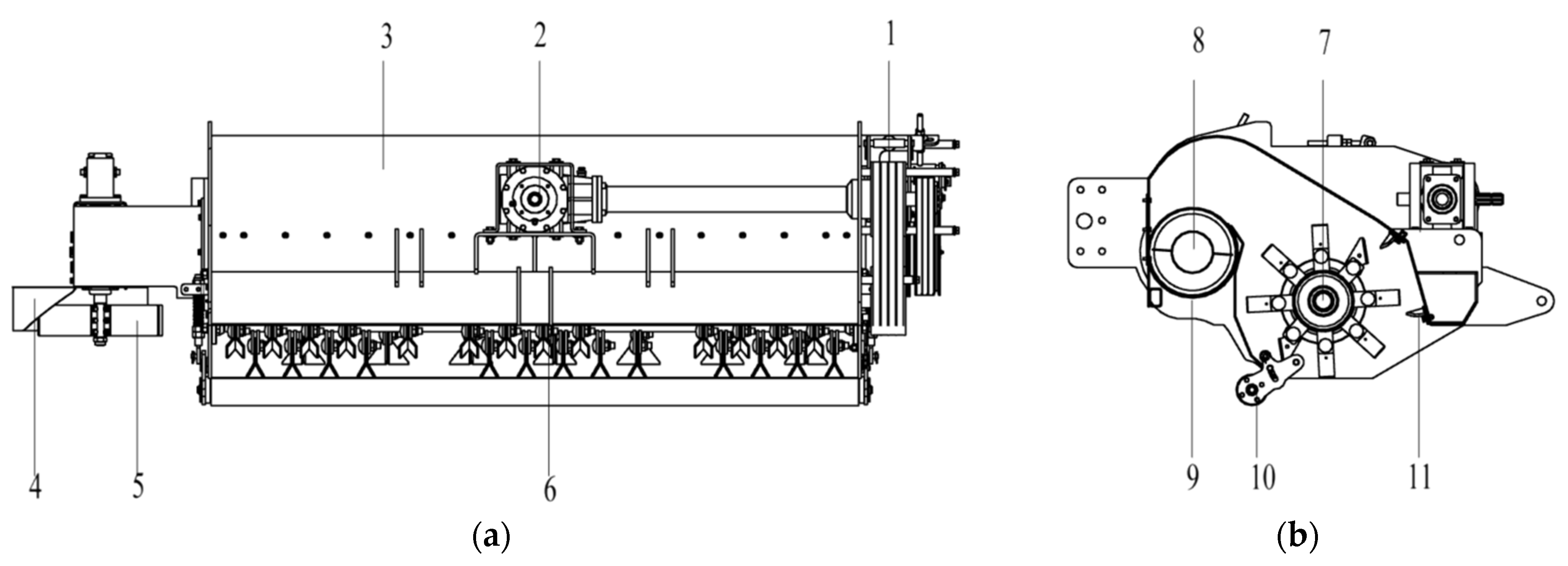
The straw-crushing and returning device of the follow-up residual film recycling machine is mainly composed of a crushing knife shaft assembly, a screw conveying device, a transmission system, a fixed knife, a pressing film wheel, a throwing device and other parts. The whole structure is shown in
Figure 1.
The machine is connected to the tractor by a three-point suspension device, and the height of the machine is adjusted by the tension rod of the pressing film wheel to control the height of the straw stubble [
10,
11,
12,
13,
14,
15]. During the operation, the power output shaft of the tractor transmits power to the gearbox, and the power is transmitted to the pulley through the gearbox transmission, thus driving the crushing cutter shaft and the screw conveyor to rotate. When the machine is moving forward, the straw is bent at a certain angle by the front baffle of the inlet, cut by the high-speed rotating crushing flail, and the cut straw enters the crushing chamber. In the crushing chamber, it is repeatedly hit, cut and rubbed by the fixed knife and the Y-shaped crushing flail fixed inside; crushed into a broken straw with appropriate length; and then thrown to the spiral conveying device under the dual action of the flail throwing and the airflow field. At the same time, due to the high-speed rotation of the crushing cutter shaft, the gas flow rate increases, the pressure decreases and the relative external environment in the device shell is a relatively closed space. Therefore, a negative-pressure area will be formed at the entrance of the crushing chamber, and a part of the lighter impurities on the membrane surface will be sucked in and thrown to the screw conveyor. After that, the broken stalk and some impurities are transported laterally through the screw conveyor. The rotating throwing wheel is thrown to the cotton field on the right side of the moving direction of the machine after the discharge port to complete a series of operations such as cutting, crushing and throwing cotton stalks [
16,
17,
18].
In order to improve the function of airflow transportation and improve the fluidity of straw, a special flail knife named a wind knife was designed in this machine. As shown in
Figure 2. The arrangement of shredding knives and their corresponding relationship with cotton rows are shown in
Figure 3.
The flail knife is composed of two symmetrical blade combinations, and the blade surface is a triangle formed by the combination. The function of this structure is different from that of the crushing flail knife, which cuts and crushes the cotton stalk through direct contact. The wind knife is subjected to centrifugal force when it rotates at high speed, and the triangular blade surface becomes the windward side. Through its large windward area, the airflow velocity in the crushing chamber is increased, and the transportation effect of aerodynamic force on straw is improved, so that it can flow and throw out more smoothly under the action of crushing inside the wind field. And because the wind knife almost does not participate in the crushing work through physical contact with the straw, it is different from the crushing and flicking knife, which requires a certain thickness to ensure the strength of the tool. The wind knife surface can be designed to be thinner and lower in quality, thus effectively controlling the required power consumption. The design goal of this structure is to reduce the amount of broken straw falling by improving the gas fluidity in the crushing room, to improve the effect of straw conveying performance and to reduce the impact of broken straw falling on the residual film recovery operation.
Both the Y-type crushing flail and the air knife are installed on the tool holder welded to the tool shaft by a hinged connection, which can effectively avoid the rigid collision with the obstacle in the working state and cause the flail to be damaged and is convenient for maintenance and replacement.
The main technical parameters of the straw-crushing device of the follow-up residual film recycling machine are shown in
Table 1 [
19].
2.2. Simulation Model of a Straw-Crushing Device
Firstly, the three-dimensional CAD software Inventor 2020 is used to establish the three-dimensional model of the shell of the crushing chamber and the crushing device. After the modeling is completed, it is saved as x-t format. ANSYS Workbench is run, SpaceClaim is run and the simplified three-dimensional model is opened. The fluid domain is extracted by the volume extraction function, and the fluid domain is divided into a rotating domain and a stationary domain. In order to ensure that the grid nodes on the interface of the rotating domain and the stationary domain are consistent during the subsequent meshing, a shared topology needs to be specified. At this time, the extracted fluid domain is extracted from the solid model. The inlet and outlet of the airflow field are the actual positions in the device. The inlet is close to the rotating domain. In the subsequent Fluent calculation, it is necessary to define the pressure boundary, and the gauge pressure is 0, but there is a certain deviation from the reality. The actual situation is that the airflow inflow at the entrance has undergone certain development, and the gauge pressure is not 0. Therefore, the fluid domain model is selected to be slightly modified, and the cross-sectional area is kept the same at the entrance and slightly stretched along the normal direction of the cross-section.
For this device, it is also an indicator of smooth operation to throw the crushed straw smoothly from the crushing chamber into the screw conveyor. Therefore, this part of the model cannot be ignored. It is necessary to model the material trough channel after the outlet of the crushing chamber and set the outlet surface of this part as the outlet of the whole airflow field. The simplified model is shown in
Figure 4.
After the processing of the fluid domain model is completed, the meshing is opened, and the extracted fluid domain is meshed. Since the rotating domain contains the crushing cutter shaft part, the fluid domain model is more complex and requires a more refined grid compared with the static domain. Therefore, the grid cell size is set to 20 mm in the static domain and 9 mm in the fluid domain, and a wall expansion with a layer number of 3 and a growth rate of 1.2 is set for the wall formed after the crushing cutter shaft is extracted. The quality of the grid is checked after the division. Here, two parameters are selected as the basis, which are skewness and aspect radio. Among them, skewness is one of the primary quality criteria of the grid, with a value of 0~1; the closer to the 0 grid, the higher the quality. The aspect radio value is greater than 1, and the closer it is to 1, the higher the mesh quality is. After the meshing is completed, the average values of grid skewness and aspect radio in quality are 0.23 and 1.84, respectively, which meet the requirements of numerical simulation. The total number of grids is 5583569, and the crushing chamber after meshing is shown in
Figure 5.
2.3. CFD Software Parameter Settings
2.3.1. Fluid Mechanics Control Equations and Model Selection
The fluid flow in the basin should follow the law of conservation of physics, including the law of conservation of mass, the law of conservation of momentum and the law of conservation of energy, and the flow in the turbulent state should also follow the turbulent transport equation [
20,
21,
22,
23,
24].
- (1)
Mass conservation equation
Also known as the continuity equation, the increase in the mass of the fluid micro-element per unit time should be equal to the net mass flowing into the micro-element at the same time [
25].
Divergence is introduced,
, and combined with Formula (1).
For incompressible fluids, the density is constant; in this case, Equation (2) can be simplified to the following:
- (2)
Momentum conservation equation
All fluid systems also need to satisfy the law of conservation of momentum; that is, the rate of change of fluid momentum in the micro-unit is equal to the sum of all the forces on the system [
26].
In the formula:
ρ is the pressure on a micro-element, τ is viscous stress on the micro-element and F is physical strength on the micro-element.
- (3)
Energy conservation equation
For incompressible flow, the heat exchange is very small, so the energy conservation equation is not considered.
- (4)
Model selection and transport equation
The flow field in the crushing chamber is dominated by turbulence, and the turbulence model should be selected. There are many turbulence models available in Fluent [
27], but there is no general choice that can be suitable for various flow conditions. Among many turbulence models, the k-ε model has good calculation stability, high efficiency, is a simple model and is widely used in various turbulence simulations [
28,
29]. The k-ε model includes standard k-ε, RNG k-ε and realizable k-ε. Standard k-ε is a semi-empirical model. Based on the transport equation of turbulent kinetic energy K and its dissipation rate ε, RNG k-ε considers the influence of eddy current on turbulence compared with realizable k-ε [
30], which improves the accuracy of eddy current flow. The current research on the realizable k-ε model shows that it performs well in the calculation of separated flow and complex flow with secondary flow. However, for the flow field with both rotating domain and stationary domain, non-physical turbulent viscosity will be generated, which is not suitable for the simulation of MRF. Therefore, the turbulence model is the RNG k-ε two-equation model [
31], and the wall function is the standard wall function. The RNG k-ε transport equation is as follows:
Quorum
Farther
In the formula: C1ε = 1.42, C2ε = 1.68.
2.3.2. Boundary Conditions
Firstly, the grid size is checked, and the parameter setting is started after the non-negative volume grid is determined. It is regarded as incompressible flow, the fluid medium is air, the temperature is 15 °C, the density is 1.225 kg/m
3, the viscosity is 1.7894 × 10
−5 kg/m·s and the operating pressure is 101,325 Pa (a standard atmospheric pressure). The influence of solid flow (straw, impurities, etc.) and gravity on the characteristics of the airflow field and the energy change caused by friction between the components when the straw-crushing device is working is ignored [
32]. The pressure–velocity coupling uses the coupled coupling algorithm. In terms of spatial discretization, considering the calculation accuracy, the second-order upwind scheme with high accuracy is selected for momentum. In terms of boundary conditions, the inlet and outlet conditions of pressure inlet and outlet are selected, respectively, and the gauge pressure is set to 0 Pa (the relative pressure value with the operating pressure is at standard atmospheric pressure); the reference frame model uses the MRF (multiple reference frame) model. The unit area condition of the rotation domain is set as the motion reference frame, and the rotation axis direction and rotation speed are set. The stationary domain is in the fixed reference frame, and the boundary between the rotation domain and the stationary domain is set as the interior boundary. After the setting is completed, the initialization and calculation begin.
2.3.3. Simulation Results and Post-Processing
After the calculation is completed, Fluent is used to draw the pathlines in the crushing chamber of the straw-crushing device, which represents the trajectory curve of the fluid particle flow in continuous time. The pathlines can be used to observe the airflow movement law in the crushing chamber. The drawing results are shown in
Figure 6.
The coloring variable of pathlines is set to Particle ID, and the distribution form of pathlines can be clearly seen. The drawn pathlines can generate flow animation through the pulse function. From the flow animation, it can be intuitively observed that the particle motion is generally rotated with the crushing tool shaft after entering from the inlet, and then flows out from the outlet, which is in line with the actual operation of the machine. Although the three-dimensional diagram can display the airflow field more intuitively, it is more cluttered, and the near-wall area will change sharply due to the influence of the wall surface, which is not conducive to subsequent analysis. Therefore, CFD-Post is used for post-processing.
The numerical simulation results are imported into CFD-Post. In order to facilitate the description and analysis, five planes are established in the crushing chamber as shown in
Figure 7, and P1~P3 are perpendicular to the Z axis. Combined with the grouping characteristics of the designed blade, the P1 section is located between the two groups of blades on the left side of the crushing chamber (Z = 650 mm), P2 is the symmetry plane of the crushing chamber (Z = 1050 mm) and P3 passes through the right side of the blade group (Z = 1800 mm); the P4 section is perpendicular to the
X axis and runs through the center of the grinding tool axis (X = 0 mm); the P5 section is perpendicular to the X axis, which is the interface between the crushing chamber and the transverse conveying device (X = −290 mm).
2.4. Field Trial Program
On the basis of three-dimensional modeling and computational fluid dynamics (CFD) software Fluent 19.2, the prototype was manufactured, and the working effect of the machine was tested in the field under the conditions of different rotational speed of the cutter shaft, the forward speed of the machine and the height from the ground at the end of the cutter. The qualified rate of straw-crushing length and the falling rate of the broken straw were investigated under different operating parameters. Then, the parameters were optimized by Design-Expert 13 software to determine the optimal working parameter combination. Finally, the rationality of the device was determined by comparative test with conventional machines and tools.
3. Results and Discussion
3.1. Analysis of the Velocity Vector Diagram and Streamline Diagram of the Crushing Chamber
Figure 8 is the velocity vector diagram and streamline diagram of the cross-section P1~P3. The highest value of the airflow velocity of the three sections appears at the end of the tool, and the velocity is lower at the inlet and outlet far away from the tool axis. The streamline and velocity vector direction are in line with the operation of the device. In the near-wall region near the shell of the device, the velocity vector distribution shows that the airflow velocity near the upper shell is slightly larger than that in other near-wall regions. At the same time, it can be seen from the streamline diagram of P1~P3 that there is a certain degree of eddy current in all three sections. The vortex is basically distributed between the cutter shaft and the outlet of the flow field, and the airflow in this area will affect the process of the broken stem from the cutter shaft until the broken stem falls into the trough. If the broken stalk is affected by the eddy current in this area, it is possible to return to the cutter shaft operation area after being thrown from the cutter shaft to achieve the effect of repeated crushing, but it also increases the possibility of the broken stalk falling off the surface. The airflow vector at the entrance of the crushing chamber is more regular, generally upward from the entrance. It can be concluded that the movement law of straw under the influence of aerodynamic force in the crushing chamber is as follows: It is attracted to the entrance of the crushing chamber and enters the crushing chamber upwards. After rotating with the cutter shaft, most of the straw will be thrown out along the wall surface of the upper shell of the machine, and a small part will be affected by the eddy current and re-enter the working area of the flail.
Figure 9 is the velocity vector diagram of the P5 section. Most of the velocity vector directions are from the inside of the crushing chamber to the outside, and a few directions are from the outside to the inside. The velocity of the outflow part is generally higher than that of the reflux part, which proves that there is still a small part of the reflux at the P5 section, which affects the throwing performance of the broken stalk. The maximum velocity appears at the wall of the upper shell, which corresponds to the previous velocity vector analysis results of the P1~P3 sections. It can be seen that the movement law of the broken stalk under the action of airflow in this part should be that most of the broken stalk is thrown along the upper shell of the machine with the airflow to the trough of the spiral conveying device, and a small part will re-enter the crushing chamber area.
3.2. Analysis of the Pressure Field in the Crushing Chamber
Figure 10a is the pressure cloud diagram of the P4 section. It can be seen from the diagram that the closer to the rotation center of the tool axis, the smaller the pressure is, and the trend of increasing gradually from the rotation center to both sides is presented.
Figure 10b is the inlet pressure cloud diagram of the crushing chamber. The pressure distribution of the whole inlet surface is basically negative pressure, and the maximum negative pressure value reaches −24.41 Pa. Only a small part of the positive pressure appears on this surface, and the maximum value reaches 14.797 Pa, which appears in the edge area of the inlet surface, that is, the near-wall area. The negative pressure on the inlet surface is conducive to the smooth feeding of straw, especially the lodging straw. At the same time, some light impurities and scattered straw can be inhaled. However, excessive negative pressure has the risk of the film breaking. Considering the subsequent residual film recovery operation, the negative pressure should not be too large.
Figure 11a is the surface pressure cloud diagram of the cutter shaft in the crushing chamber, and
Figure 11b is the pressure cloud diagram of the P1~P3 sections. Combined with the two figures, it can be seen that under the working condition of the machine, the high-pressure area in the crushing chamber is concentrated at the end of the blade cutter; the pressure on the windward side of the wind knife is larger than that of the surrounding area, and a small high-pressure area appears. The pressure on the leeward side of the wind knife is smaller than that of the surrounding area, and an area with higher negative pressure appears. At the same time, it can be seen from
Figure 11b that the pressure distribution in the crushing chamber increases radially along the rotation center of the crushing cutter shaft, and in addition to the end of the flail cutter, there is also a relatively high-pressure area at the broken line of the upper shell and the lower shell of the machine, indicating that the sharp change of the inner-wall shape can easily cause a sudden change in air pressure.
3.3. The Influence of Cutter Shaft Speed on the Entrance
The size of the negative pressure at the inlet determines whether the straw is fed, and some surface impurities can be sucked in smoothly. As shown in
Figure 12, the pressure distribution at the inlet of the flow field in the crushing chamber at three different speeds is shown respectively. The pressure cloud diagram at different speeds shows a very small part of the positive pressure area, and it is concentrated in the near-wall area near the shell of the machine, and the rest is the negative-pressure area. The higher the speed is, the larger the area of the relatively high negative-pressure area is. At a speed of 1600 rpm, the maximum negative pressure at the inlet surface of the flow field is 23.4 Pa, while at the speeds of 1800 rpm and 2000 rpm, it reaches 42.54 Pa and 63.6 Pa, respectively, which is 91% and 169% higher than that at the speed of 1600 rpm.
A table is established in CFD-Post, and the mass flow rate of the inlet surface can be obtained by inputting = massFlow ( ) @ inlet. The values are 1.28 kg/s, 1.58 kg/s and 1.64 kg/s, respectively, at three speeds. According to these data,
Figure 13 is drawn. It can be seen from the figure that increasing the rotation speed of the cutter shaft can increase the maximum negative pressure value at the inlet end and increase the mass flow rate at the inlet surface. Generally speaking, this is conducive to the feeding of straw and the inhalation of impurities. However, too high a negative pressure is also accompanied by the risk of tearing the mulch film. Therefore, the operation efficiency cannot be improved simply by increasing the rotation speed of the cutter shaft.
3.4. Effect of Cutter Shaft Speed on Fluidity
Figure 14 is the streamline diagram of the cross-section P1~P3 at different tool shaft speeds, and the three sections have different degrees of eddy current phenomenon at different speeds. In
Figure 14a, the more serious vortex phenomenon of the P1 section appears in the process of the broken stalk discharged from the crushing chamber. When the rotational speed is 1600 rpm, there are two eddy currents, which appear in the connection part of the crushing chamber and the material trough. When the rotational speed is 1800 rpm, the eddy current is closer to the crushing cutter shaft, and the eddy current area is larger. The streamline is more irregular. When the rotational speed reaches 2000 rpm, the streamline of the connection part of the crushing chamber and the material trough appears stratified. At this time, the throwing performance of the broken stalk is extremely poor.
It can be seen from
Figure 14b that when the rotational speed of the P2 section is 1600 rpm, there is an eddy current at the junction of the feed tank, and when the rotational speed is 1800 rpm, the eddy current area at this place increases, and the crushing chamber at the entrance of the crushing chamber and the connecting part of the crushing chamber and the feed tank are layered. When the rotational speed is 2000 rpm, this phenomenon intensifies, and the fluidity of the broken stalk will be affected. It can be seen from
Figure 14c that there is no obvious backflow in the cross-section of P3 at the speed of 1600 rpm, but there is a slight upward trend after the streamline flows out from the outlet of the crushing chamber. When the rotational speed is 1800 rpm and 2000 rpm, the streamline is extremely irregular, which seriously affects the fluidity and throwing performance of the broken stalk in the crushing chamber.
Through the above analysis, it can be judged that the change in the rotation speed of the cutter shaft has different effects on each position in the crushing chamber, especially on the process of crushing and throwing. On the whole, for the structure of this device, too high a rotation speed of the cutter shaft will make the streamline more disordered and reduce the fluidity and throwing performance of the straw in the crushing room.
3.5. Effect of Forward Speed of the Machine on Straw Feeding
Figure 15 is the pressure cloud diagram of the entrance of the crushing chamber at different forward speeds. From the diagram, it can be seen that at different forward speeds, the entrance surface can maintain a large area of negative-pressure area. At three forward speeds, the mass flow rates of the entrance surface are 1.34 kg/s, 1.31 kg/s and 1.29 kg/s, respectively. It can be seen that increasing the forward speed of the machine will reduce the straw feeding and impurity suction performance at the entrance of the crushing chamber.
3.6. The Influence of the Forward Speed of the Machine on the Fluidity
Figure 16 is the streamline diagram of P1, P2 and P3 at different forward speeds.
Figure 16a shows the P1 section; when the forward speed is 5 km/h, there is a complex eddy current in the upper part of the material groove of the screw conveying device, and with the increase in the forward speed, the fluidity here has not been significantly improved. In
Figure 16b, there is a large eddy current above the outlet of the flow field in the P2 section at three different forward speeds, and the area of the eddy current increases slightly with the increase in the forward speed of the machine. The eddy current here will disturb the backward throwing performance of the broken stalk.
Figure 16c shows that at the cross-section of P3, the streamlines above the feed slot are very disordered at three forward speeds, which seriously affects the throwing performance of the broken stalk to the feed slot.
On the whole, for the structure of the device, the increase in the forward speed has no obvious effect on the fluidity of the crushing chamber. Different forward speeds are relatively stable in the area from the entrance of the crushing chamber to the high-speed rotating tool shaft, and the influence of the forward speed of the machine is not large, but the flow line at the junction of the crushing chamber and the spiral conveying device is more disordered. This part of the complex eddy current will affect the process of throwing the broken stalk from the crushing chamber to the material trough. Considering the structure of the device here, it should be caused by the complex shape change of the inner-wall surface in this interval.
3.7. Effect of the Wind Knife on Flowability
The air knife plays a role in increasing the airflow velocity of the crushing chamber and improving the flow field fluidity of the crushing chamber in this device. The number of air knives will affect the improvement effect of the above effects. Considering the factors such as the arrangement of the cutter shaft and the power consumption of the machine, the numerical simulation is selected. The air knife design and the number of air knives are 8 and 14, respectively, and other parameters are kept unchanged. When it is designed without an air knife, it is equivalent to reducing the arrangement of two rows of flail knives in the tool shaft. Therefore, the angle between each two rows of knives should be changed from 45° to 60° at the same time, so as to meet the requirements of conventional machine design, and other parameters remain unchanged.
Figure 17 is the streamline diagram of the cross-section P1~P3 under different numbers of air knives. It can be seen from
Figure 17a that in the case of no air knife, the airflow flows smoothly from the inflow to the rotation with the cutter shaft, and the fluidity is good. However, in the interval from the outlet of the crushing chamber to the outlet of the fluid domain, laminar flow occurs, and the streamline distribution is very messy, which will seriously affect the throwing performance of the broken stalk to the trough. When eight air knives are set, the fluidity in the interval from the outlet of the crushing chamber to the outlet of the fluid domain is slightly improved, but a vortex appears at the inlet of the crushing chamber. When the number of air knives is set to 14, there are two smaller vortices outside the outlet of the crushing chamber, and there is no obvious stratification in the whole flow field streamline, which proves that the setting of the air knife has significantly improved the fluidity here.
It can be seen from
Figure 17b that under the design of the cross-section P2 without the air knife, the streamline of the airflow from the inlet to the crushing knife shaft is more disordered, which affects the feeding performance of the straw. The stratification phenomenon appears in the interval from the crushing knife shaft to the outlet of the flow field. When eight air knives are set, the feeding performance of the straw is improved to a certain extent, and a small eddy current appears at the throwing place. When the number of air knives is 14, the streamline condition of the feeding process is obviously improved, and the stratification phenomenon of the streamline in the throwing process disappears, but an eddy current appears. It can be seen from
Figure 17c that there is an obvious eddy current near the outlet of the flow field in the structure without an air knife, and laminar flow appears at the connection between the crushing chamber and the material tank. When eight air knives are set, there is still an eddy current, but there is no obvious laminar flow phenomenon. When setting 14 air knives, a small area of eddy current appears near the wall of the upper shell of the machine, but the overall streamline stratification is improved.
From the above analysis, it can be seen that for the middle area of the crushing chamber, the setting of the air knife effectively improves the feeding performance of the straw and avoids the streamline stratification phenomenon in the crushing straw throwing interval but also produces a vortex; on both sides of the area, the design of the wind knife improves the fluidity, reduces the area of the eddy current zone, reduces the number of eddy currents, improves the phenomenon of partial streamline stratification and effectively improves the fluidity of the straw and the throwing performance of the broken straw to the material trough. In terms of flow velocity, under three different designs, the peak flow velocity inside the crushing chamber is 43.1 m/s, 50.1 m/s and 54.48 m/s, respectively. It is proved that although the design of the air knife will cause a certain vortex in the central area of the crushing chamber, it will significantly improve the flow on both sides of the crushing chamber and can effectively improve the airflow velocity in the flow field. The feasibility of the new blade of the air knife is verified in theory.
3.8. Field Experiment
3.8.1. Test Conditions
In order to verify the results of the simulation analysis, a field experiment was carried out in 145 Regiment of Shihezi City on 27 October 2021 (
Figure 18).
The test conditions are as shown in
Table 2, according to GB/T 24675.6-2021 Conservation Tillage Machinery Part 6: Straw-crushing and returning machine 8.2.2.3. For straw moisture content and yield determination, the cotton stalk moisture content determination formula is as follows:
In the formula:
Hj is moisture content of cotton stalk (mass fraction), Mjs is wet cotton stalk quality and Mjg is dry cotton stalk quality.
3.8.2. Test Results and Analysis
The field verification test adopted the method of quadratic regression orthogonal combination of three factors and three levels, and a total of 17 groups of tests were carried out, as shown in
Figure 19; the test results are given in
Table 3.
In order to verify the difference in the operation effect of the straw-crushing device with or without the air knife structure, a comparative test was carried out. The parameters of the machine used in the comparative test are shown in
Table 4, and the comparative test models are shown in
Figure 20.
The results of parameter optimization using Design-Expert are as follows: the rotation speed of the cutter shaft is 1770.1 rpm, the forward speed of the machine is 6.03 km/h and the height of the tool end from the ground is 80 mm. The qualified rate of crushing length can reach 93.1%, and the straw drop rate is 3.4%. In order to verify its reliability, the above parameters were rounded in combination with the actual operating parameters of the machine. Three tests were carried out using the parameter combination of a cutter shaft speed of 1800 rpm, a forward speed of the machine of 6 km/h, and a height of the tool end from the ground of 80 mm. The test results were averaged. The qualified rate of straw-crushing length was 94.13%, and the straw drop rate was 4.26%. The relative errors with the predicted values were 1.03% and 0.86%, respectively. The degree of dispersion was small, which proved that the reliability of the optimization model was good, indicating that the operation quality of the straw-crushing device met the national standards, and it has a lower straw drop rate.
The field test results show that the optimal parameter combination of this machine is as follows: the rotation speed of the tool shaft is 1800 rpm, the forward speed of the machine is 6 km/h and the height of the tool end from the ground is 80 mm. Under this operating condition, the qualified rate of straw powder length crushing was 94.13%, and the straw falling rate was 4.26%.
The optimal working parameters in the verification test were adopted in the comparison test. The rotation speed of the tool shaft was 1800 rpm, the forward speed of the machine was 6 km/h, and the height of the tool end from the ground was 80 mm. The evaluation indexes were the same as the qualified rate of straw-crushing length and the straw drop rate. The test was carried out three times, and the data were averaged. Finally, the qualified rate of straw-crushing length of the comparison model was 93.5%, and the straw drop rate was 7.83%.
The results of the field experiment showed that the qualified rate of straw-crushing length gradually increased with the increase in the rotation speed of the cutter shaft, but the increase gradually slowed down. This was due to the increase in the rotation speed of the cutter shaft. The amount of repeated crushing of straw also increased. The qualified rate of straw-crushing length also decreased with the increase in the forward speed of the machine, and the decrease gradually increased. The field experiment results showed that the straw drop rate decreased with the increase in the height of the tool end from the ground and varied randomly with forward speed increases and decreases. The comparative test results show that the setting of this wind knife structure makes the qualified rate of straw-crushing length slightly increased, and the straw drop rate is significantly reduced. The test results are consistent with the simulation results, which proves the accuracy of the analysis [
23]. The results show that the qualified rate of straw crushing of this structure meets the requirements of relevant national standards and can effectively reduce the rate of broken straw falling, thus indirectly reducing the impurity rate of residual film recovery.
4. Conclusions
In this paper, aiming to address the problem that the quality of cotton stalk crushing and returning to the field before the residual film recovery operation in Xinjiang is not high and the broken stalk falls seriously, which leads to the high impurity rate of the residual film, a straw-crushing device with a follow-up residual film recovery machine is designed. The main research conclusions are as follows:
- (1)
The CFD numerical model of the comminution chamber of the horizontal straw comminution device was established, and the airflow characteristics and air pressure distribution law in the comminution chamber were revealed. The direction of the airflow vector in the comminution chamber is basically from the inlet of the flow field to the cutter axis area, which rotates along the cutter axis and then from the outlet of the flow field along the shape of the device shell; the streamline flows smoothly between the flow field inlet and the rotating field through the high-speed rotation of the cutter shaft, resulting in eddy current and stratification in the streamline disorder from the rotating field to the flow field outlet; a large area of negative pressure is produced at the entrance of the flow field, and the pressure on the windward side is relatively higher, while the pressure on the leeward side is lower.
- (2)
By changing the rotation speed of the cutter shaft, it is concluded that when the rotation speed of the cutter shaft is 2000 rpm, the negative pressure and mass flow rate of the inlet surface of the flow field reach the maximum, which is 63.6 Pa and 1.64 kg/s, respectively, which proves that the rotation speed of the cutter shaft increases, and the feeding performance also increases. However, for the structure of the machine, the flowability of the straw in the crushing room decreases with the increase in the rotation speed of the cutter shaft, so it is necessary to find a balance point. By changing the forward speed of the machine, it is concluded that increasing this value can effectively improve the throwing performance of the broken stalk to the trough. In the case of 0, 8 and 16 air knives, the peak flow velocity in the crushing chamber is 43.1 m/s, 50.1 m/s and 54.48 m/s, respectively, and the airflow in the crushing chamber is improved to a certain extent, which proves the feasibility of the air knives’ structure.
- (3)
In the simulation and the field experiment, the speed of cutter shaft is 1800 rpm, the speed of advance is 6 km/h, the height of cutter end from the ground is 80 mm, the qualified rate of straw-crushing length is 94.13% and the rate of straw falling is 4.26%. The field operation effect of this machine was under this combination of parameters. The results of the field experiment and simulation show that the qualified rate of straw-crushing length increases gradually with the rotating speed of the cutter shaft, but the increase is gradual, and the range is gradually intensified with the acceleration of the forward speed of machines and tools. The straw drop rate varies with the advancing speed randomly with the height of the tool end from the ground. With the setting of the air knife structure, the qualified rate of straw-crushing length is slightly increased, and the straw falling rate is obvious.
The equipment studied in this paper has been optimized to improve the crushing rate of straw and the falling rate of broken straw, which saves the cost for farmers and lays a foundation for throwing straw back to the field. In the correlation between straw crushing and returning to the field operation and residual film recovery operation, in addition to the straw loss rate affecting the residual film impurity rate, if the cotton stalk stubble section quality is poor, the fiber and phloem residues are too much or the stubble height is too high, it may also tear the film, thus affecting the integrity of the recovered film. In the later stage, we can try to add the test index of plastic film integrity in the test and more comprehensively reveal the relationship between straw crushing and returning to the field and residual film recovery.


