Article

Improved Real-Time Models for Object Detection and Instance Segmentation for Agaricus bisporus Segmentation and Localization System Using RGB-D Panoramic Stitching Images

1
College of Intelligent Equipment, Shandong University of Science and Technology, Tai’an 271019, China
2
College of Mechanical and Electronic Engineering, Shandong Agricultural University, Tai’an 271018, China
*
Author to whom correspondence should be addressed.
Agriculture 2024, 14(5), 735; https://doi.org/10.3390/agriculture14050735
Submission received: 28 March 2024 / Revised: 5 May 2024 / Accepted: 7 May 2024 / Published: 9 May 2024

Abstract

:
The segmentation and localization of Agaricus bisporus is a precondition for its automatic harvesting. A. bisporus growth clusters can present challenges for precise localization and segmentation because of adhesion and overlapping. A low-cost image stitching system is presented in this research, utilizing a quick stitching method with disparity correction to produce high-precision panoramic dual-modal fusion images. An enhanced technique called Real-Time Models for Object Detection and Instance Segmentation (RTMDet-Ins) is suggested. This approach utilizes SimAM Attention Module’s (SimAM) global attention mechanism and the lightweight feature fusion module Space-to-depth Progressive Asymmetric Feature Pyramid Network (SPD-PAFPN) to improve the detection capabilities for hidden A. bisporus. It efficiently deals with challenges related to intricate segmentation and inaccurate localization in complex obstacles and adhesion scenarios. The technology has been verified by 96 data sets collected on a self-designed fully automatic harvesting robot platform. Statistical analysis shows that the worldwide stitching error is below 2 mm in the area of 1200 mm × 400 mm. The segmentation method demonstrates an overall precision of 98.64%. The planar mean positioning error is merely 0.31%. The method promoted in this research demonstrates improved segmentation and localization accuracy in a challenging harvesting setting, enabling efficient autonomous harvesting of A. bisporus.

1. Introduction

A. bisporus, widely cultivated as an edible mushroom, is renowned for its delectable taste and rich nutritional content [1,2]. However, against continuous growth in large-scale production, harvesting A. bisporus remains labor-intensive and heavily dependent on skilled workers. Labor costs and harvesting efficiency emerge as primary constraints affecting productivity development [3]. Machine vision-based methods for the segmentation and localization of A. bisporus have gained widespread application in agricultural harvesting robot platforms, owing to their advantages such as automation, real-time capability, non-contact nature, and repeatability [4,5]. These methods are extensively helpful in agricultural harvesting robot platforms [6,7].
The accurate contour segmentation and precise identification of optimal harvesting points for A. bisporus are prerequisites for efficient harvesting. Segmentation and localization are typically handled by the visual module of the harvesting robot, equipped with an independent information system. However, in a factory-scale cultivation environment, the narrow working space of single-layer mushroom beds makes it challenging to provide sufficient distance for obtaining a panoramic field of view. Particularly, the clustered growth habits of A. bisporus result in substantial occlusion, making it difficult for the visual system to accurately segment and locate the optimal harvesting points [8]. The ability to segment and locate in complex cultivation environments is a prerequisite for achieving efficient harvesting, and the development of machine vision brings hope to address this challenge.
Reed et al. [9] pioneered designing a mushroom harvesting robot based on two-dimensional vision in the United Kingdom. In laboratory conditions, they captured the positional information of mushrooms through cameras to guide the mechanical arm in completing the harvesting task. However, they did not address the overlapping issue in the A. bisporus case. Yu et al. [10] introduced a mushroom image region labeling technique based on sequential scanning, using numbers to label the central area of individual mushroom images, thereby achieving differentiation of mushroom images. However, this method merely allows rough segmentation, and lacks precision in localization. Refs. [11,12] proposed a preliminary segmentation algorithm and a novel iterative label generation method for initial watershed marking. Although these methods achieved a 95.7% accuracy in the effective recognition of A. bisporus, significant errors persisted in the radius fitting of the mushrooms. Furthermore, a method involving the computation of a global gradient threshold was introduced. It segmented the image based on the edge gradient features, generating a binary image that underwent filtering and morphological processing. This resulted in an effective recognition rate of over 96% for A. bisporus. However, the overall operational efficiency remained low due to the excessive computational workload [13].
Visual solutions based on RGB two-dimensional images encompass various mechanisms and technologies, but they struggle to attain high-precision depth information for the target. Unlike traditional RGB cameras, depth cameras employ an active imaging approach, providing depth information and proving more suitable for the complex lighting conditions in A. bisporus cultivation scenes than color cameras. Nathanael et al. [14] proposed an approach that initially segments using RGB information, then employs the Hough transform to determine the center and radius and, finally, utilized depth information to provide harvesting height for the mechanical arm. However, this method only utilizes depth information to determine the height coordinate, and does not enhance the accuracy of the segmentation and localization algorithm. According to recent research, a depth map stitching approach incorporating parallax correction and a layered watershed algorithm based on depth maps achieved a detection rate of 95.82% for occluded bilateral mushrooms in limited planting conditions. This approach may not correctly address complex planting conditions due to the simple dataset employed. However, the picture acquisition approach in the first phases has greatly inspired our research [15].
In recent years, deep learning technology has been widely used in the field of image segmentation. Compared to traditional instance segmentation methods, CondInst [16] simplifies the network architecture by dynamically generating a specific mask for each instance, eliminating the need for ROI cropping and feature alignment. It significantly simplifies the network structure and reduces the computational burden. SOLOv2 [17] introduces several innovations on the original SOLO instance segmentation network. These include using Matrix NMS to improve instances’ positioning and segmentation accuracy. However, its performance could be improved when dealing with highly overlapping objects or extremely complex scenes. Zhong et al. [18] proposes a fully automated picking robotic system that is capable of planning and picking overlapping, dense, and discrete A. bisporus clusters in the field of view. The system was tested in a real A. bisporus factory, and the success rate of the robot picking A. bisporus was 94.1%. The above research shows that the deep learning model can handle complex image segmentation tasks in close to real-time, and has become the preferred technology for achieving efficient and accurate instance segmentation.
In summary, it has become increasingly challenging for traditional methodologies to achieve breakthroughs in the recognition of A. bisporus. The advantages of deep learning-based segmentation algorithms are becoming increasingly prominent. Through analysis, it has been found that the majority of missed detections in current algorithms are due to occlusion of clusters of A. bisporus in complex environments. Building upon this premise, this paper proposes a high-precision segmentation and localization system for A. bisporus to enhance the algorithm’s ability to extract features from small targets and address the challenge of accurately segmenting A. bisporus in complex environments. By incorporating a disparity-corrected fast stitching algorithm and an improved RTMDet-Ins instance segmentation network, the accuracy of segmentation and localization in complex cultivation environments is greatly enhanced. The key innovations and contributions of this research can be summarized as follows:
  • To obtain panoramic information in low-visibility working environments, this paper introduces a cost-effective and high-precision image stitching method. The method utilizes multiple local color images and depth information with the fast-stitching algorithm to acquire a high-precision panoramic image through bimodal fusion.
  • This paper proposes using SimAM’s global attention mechanism and SPD-PAFPN’s lightweight feature fusion module in the RTMDet-Ins instance segmentation network model to address the extensive occlusion caused by A. bisporus’ clustered growth habits. This enhancement improves the handling capability of occluded A. bisporus and small-sized targets. Furthermore, the segmentation and detection capabilities of occluded areas for A. bisporus are further elevated by employing bimodal fusion images.

2. Materials and Methods

2.1. Harvest Robot Design

The harvesting robot for A. bisporus is equipped with three modules: visual, harvesting, and motion control. The visual module is the only way the harvesting robot perceives the external world, and gives the harvesting robotic arm positional information on the A. bisporus. Figure 1a shows the movement flow of the visual module. The harvesting module comprises servo motors, a robotic arm, flexible suction cups, and a conveyor belt. The motion control module coordinates duties for the visual and harvesting modules. Figure 1b,c depicts both the platform design and the physical machine.
The visual module undertakes the preliminary image processing tasks of segmentation and localization for harvesting, making the rational design of the visual module crucial for ensuring harvesting efficiency. The working distance for the camera to capture a panoramic image is insufficient due to the narrow operational space of mushroom beds. For instance, when the camera is mounted at a height corresponding to the current 300 mm layer, only a field of view measuring 400 mm × 300 mm is attainable, significantly smaller than the 15,000 mm × 1200 mm expanse of mushroom beds. Therefore, the image acquisition system is designed to operate in a parallel mode, capturing local sequential images and stitching them together to generate a composite panoramic image. Additionally, the dim planting environment and extensive occlusion from clustered mushroom groups make it challenging for traditional color cameras to provide features and textures that meet the requirements of high-precision segmentation and localization.
The RealSense depth camera D435 (D435) made by American Intel Company (Santa Clara, CA, USA) is used to capture both RGB and depth images at the same time. The depth image is generated using laser speckle structured light imaging, where infrared laser emissions create diffraction patterns on the object’s surface. The depth image provides harvesting height and compensates for the lack of color texture information in dim lighting conditions through depth information. Laser speckle typically offers higher texture resolution than Time-of-Flight imaging technology. The D435 camera has a significant cost advantage compared to line laser profile measurement devices. Moreover, the D435 camera provides a depth detection range of 0.2 m to 10 m, effectively covering the planting height of A. bisporus. Therefore, the low-cost D435 camera is chosen as the visual sensing device for the harvesting robot.
The camera is driven by a servo rail with a 0.02 mm offset error and an effective motion range of 1800 mm, ensuring its horizontal movement accuracy.

2.2. Visual Module Workflow Design

The visual module captures a sequence of images, and then stitches them into a panoramic image to complete an efficient image acquisition and processing workflow. Local images are captured during the slider’s moving intervals. During the intervals when the slider is moving, local images are captured. Once the current scene capture is complete, the slider returns to the starting position. Simultaneously, the motor drives the robot to move along a horizontal rail along the edge of the mushroom bed, switching to the following local scene. The robot’s movement and image-processing tasks occur concurrently.
The premise for segmentation and localization is the acquisition of high-precision global images. Building upon efficient data collection, we propose a high-precision fusion image stitching algorithm based on disparity correction. Initially, the collected sequences of color and depth images undergo denoising using the bilateral filtering algorithm. Subsequently, a bimodal image fusion operation is performed on the color and depth images. Following this, disparity correction is applied to the images, ultimately stitching the corrected fusion images into a panoramic image.
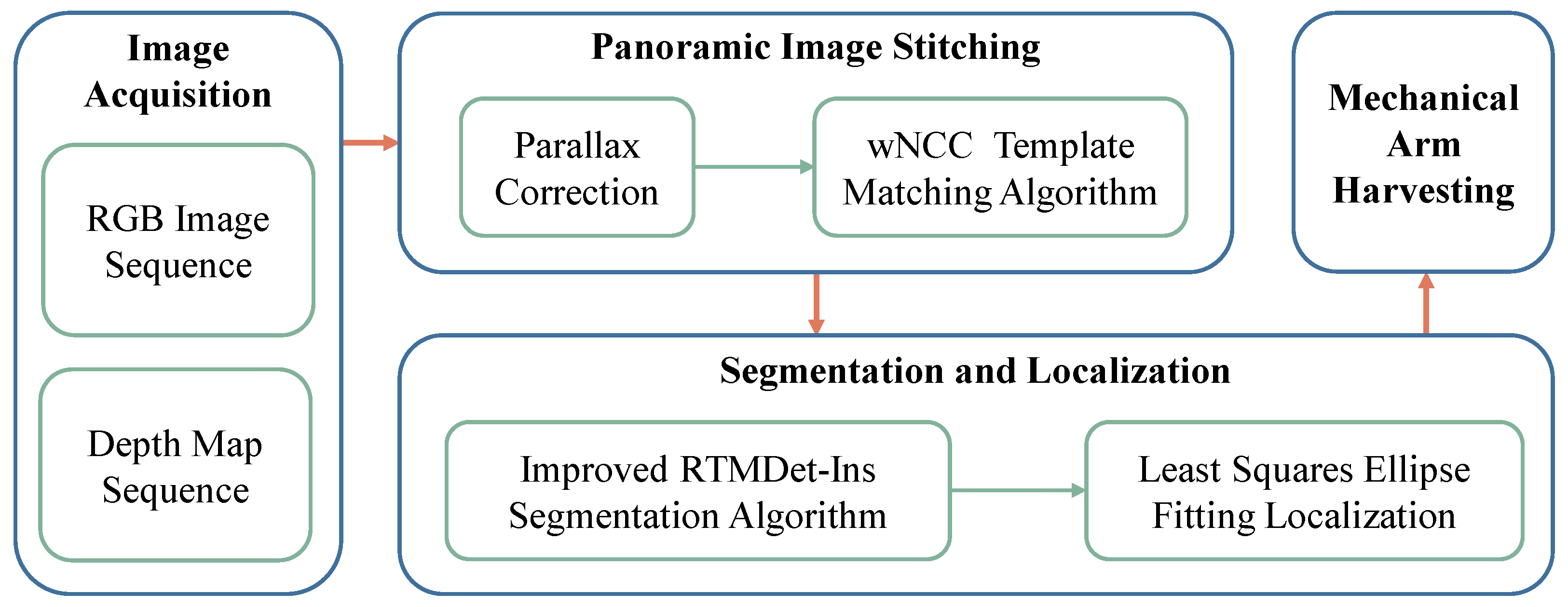
After obtaining the panoramic fusion image for the current region, the improved RTMDet-Ins model proposed in this paper is introduced to perform segmentation on the panoramic image. Subsequently, the segmentation results are fitted using the least squares method for ellipse fitting. Finally, the center of the fitted ellipse is taken as the picking point, guiding the robotic arm’s operation with depth information. The algorithm processing flow is illustrated in Figure 2.

2.3. High-Precision Fusion Image Stitching Algorithm Based on Vision Correction

Due to height restrictions between layers of mushroom beds, capturing a 1200 mm wide field of view in an instance is not feasible. Additionally, imaging at close distances introduces significant disparities, severely impacting mushroom localization accuracy. Therefore, traditional stitching methods cannot meet the precision requirements. This paper proposes an RGB-D bimodal fusion image stitching algorithm based on disparity correction, aiming to achieve panoramic image stitching within the 1200 mm range.

2.3.1. Parallax Correction

In real-world planting scenes, there are A. bisporus with varying heights. Their projected positions on the image will differ because of different depths. Therefore, the transformation relationship between two A. bisporus at different depths in each image will inevitably differ. This disparity phenomenon can lead to ghosting artifacts in the stitched image, a crucial factor affecting stitching accuracy. This paper employs a correction method to mitigate stitching errors caused by disparities. As shown in Figure 3a, for two points A and B on A. bisporus with different depths and positions, when the camera receives the capture signal at time t 1 , their projected coordinates on the imaging plane are A 1 and B 1 , respectively. Similarly, at time t 2 , the projected coordinates are A 2 and B 2 . The relative positional relationship between A and B at time t 1 is denoted as P A 1 B 1 , and the relative positional relationship is denoted as P A 2 B 2 .
By computing, we conclude that P A 1 B 1 P A 2 B 2 , indicating the need to correct disparities before image stitching to eliminate the errors caused by this phenomenon. In fact, model analysis shows that the relative positional relationship of the orthographic projections of points A and B in the image is fixed and invariant, as shown in Figure 3b.
The coordinates of point A, vertically projected onto the imaging plane in the image, are ( x 1 , y 1 ) , and its distance relative to the camera plane is d 1 . The coordinates of the camera’s optical center on the image are ( u 0 , v 0 ) , and the maximum depth value is represented by d. According to the principles of similar triangles, the following formulas can be derived:
u 0 m d = x 1 m d d 1
v 0 n d = y 1 n d d 1
After rearranging, Equations (1) and (2) become:
x 1 = u 0 d 1 d ( u 0 m )
y 1 = v 0 d 1 d ( v 0 m )
A corrected local depth map is obtained by applying Equations (3) and (4) to the depth map of A. bisporus, and the existing disparities tend to disappear. The results after disparity correction are shown in Figure 4, where Figure 4a is without disparity correction, and the positions of A. bisporus are deviated from their actual locations. Figure 4b represents the disparity correction algorithm after background separation, and the positions of A. bisporus are corrected. Figure 4c shows the before-and-after positional relationship by overlaying the original image with the corrected result.
After disparity correction, the locally corrected image will be synthesized into an RGB-D dual-modal fusion image. Dual-modal images are more suitable for high-precision segmentation, as they combine visual and spatial information. The color image conveys the texture and color details of the scene, while the depth image provides distance information for each pixel. This fusion method allows for a more accurate definition of object boundaries in the scene, thereby improving the accuracy of scene segmentation.
The D435 camera can simultaneously capture color and depth images, outputing images with registered states. The fusion of color and depth images is achieved by grayscale processing of both images and feeding them into their respective channels, as illustrated in Figure 5. Figure 5a represents the depth energy map, where the orange portion signifies compost, and the blue corresponds to A. bisporus. The varying saturation levels of blue denote the differences in elevation of the A. bisporus, with higher saturation indicating greater height.

2.3.2. Panorama Stitching

Image matching constitutes a pivotal pre-splicing step to seek images or features most akin to the given image. In this context, it is crucial to determine the optimal overlapping position between two adjacent sequential images. The template matching algorithm utilizing normalized cross-correlation exhibits remarkable robustness, manifesting substantial insensitivity to noise and outliers. It concurrently ensures precision while enhancing the real-time nature of the matching process [19]. Consequently, this manuscript adopts the weighted Normalized Cross-Correlation ( w N C C ) template matching algorithm as the fundamental strategy for image stitching. The w N C C template matching algorithm employs a sliding window to search the image to be registered, computing the similarity between the template image and the sub-image of identical dimensions. Considering the distinctive features of the A. bisporus image, the formula introduces additional weighting coefficients, as expressed in Equation (5).
w N C C ( x , y ) = i = 1 w j = 1 h ξ ( x , y ) ( I x , y ( i , j ) I ¯ x , y ) T x , y ( i , j ) T x , y ¯ i = 1 w j = 1 h I x , y ( i , j ) I x , y ¯ 2 i = 1 w j = 1 h T x , y ( i , j ) T x , y ¯ 2
where I represents the matched image, T signifies the template image, ( x , y ) denotes the current matching position, and ξ ( x , y ) represents the weighting coefficient. When ( x , y ) lies within the A. bisporus region, its grayscale value significantly surpasses that of the composting region. At this juncture, ξ ( x , y ) is set to 1, whereas it is set to 0.1 when in a non-A. bisporus region. I ¯ denotes the grayscale average of the current search region, T ¯ represents the grayscale average of the template image, and w N C C ( x , y ) signifies the degree of matching at the ( x , y ) position. The absolute value of the matching result never exceeds 1. When it equals to 1, it indicates the highest level of correspondence between the sub-image in the image to be registered and the template image, as illustrated in Figure 6a. Here, the X and Y axes denote the current coordinates, while the Z axis represents the computed result of w N C C ( x , y ) , with the yellow area indicating a high matching level. Figure 6b is the grayscale image, where the X and Y axes represent the current coordinates, and the brightness values signify the computed results of w N C C ( x , y ) . Brighter areas in the image denote higher matching degrees.
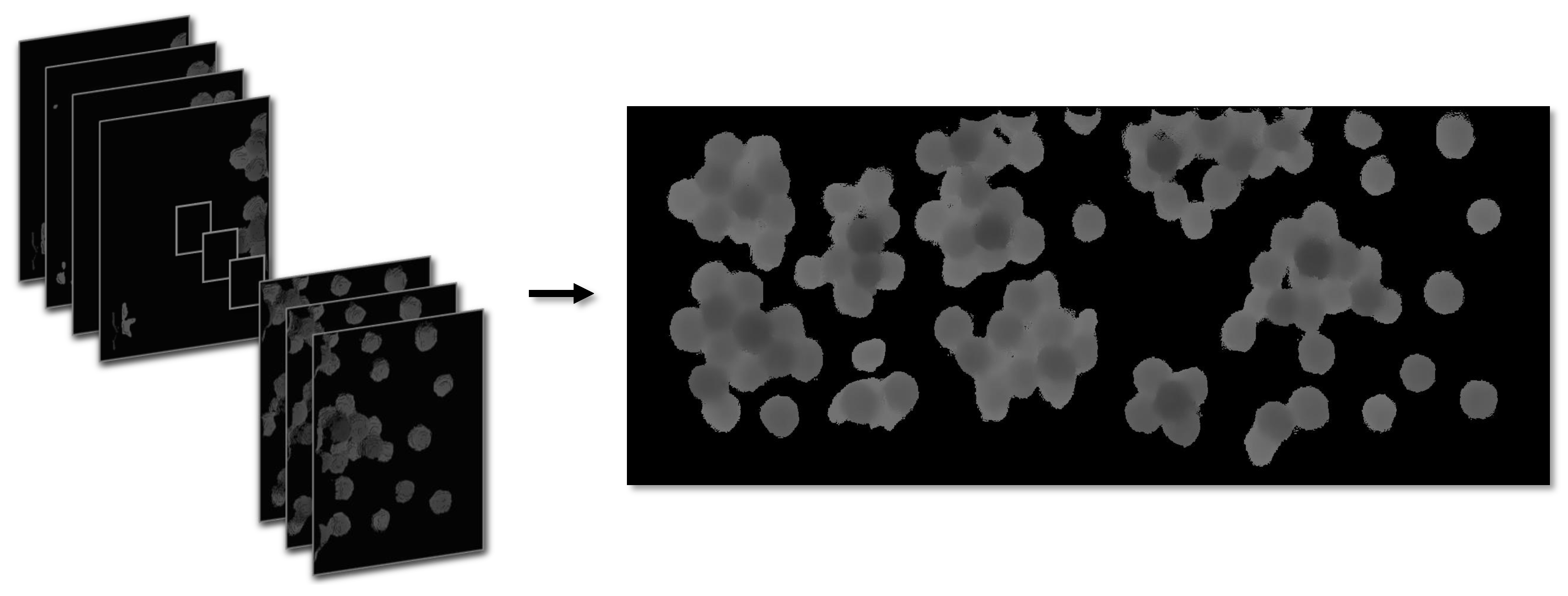
Given the corresponding states of color imagery and depth information, the stitching algorithm, aimed at reducing stitching time, computes the overlapping regions based on depth information and utilizes the computational results to merge the images seamlessly. In reality, achieving a flawless match during the matching process between adjacent images is not guaranteed on every occasion. In instances where multiple high-response regions emerge, employing color imagery for secondary verification facilitates the identification of the optimal matching window. Figure 7 illustrates a series of locally stitched images, applying a disparity correction algorithm to generate a panoramic depth map.

2.4. Improved RTMDet-Ins Fusion Image Experimental Segmentation and Localization Algorithm

RTMDet-Ins [20] is a single-stage target instance segmentation algorithm that comes with both performance and efficiency. It fully leverages the advantages of large-kernel depth-wise convolutions and a dynamic soft label assignment strategy, achieving a remarkable 44.6% Mask AP on the COCO dataset. However, the precision of A. bisporus segmentation has yet to meet the requirements for production scenarios. To further enhance segmentation precision, an analysis of segmentation failures was conducted. The clustered nature of A. bisporus led to mutual occlusion, resulting in incomplete mushroom caps in the images. Additionally, the misidentification of small-sized targets was induced by the chaotic planting environment. These factors emerge as the current algorithm’s primary constraints in segmenting and detecting A. bisporus.
This study proposes an improved instance segmentation algorithm for A. bisporus based on RTMDet-Ins, addressing the abovementioned issues. It integrates the global attention mechanism from SimAM [21] and the SPD-PAFPN feature fusion module into the RTMDet-Ins instance segmentation algorithm. The improved overall network framework is illustrated in Figure 8.
The backbone network module primarily consists of the Convolutional module and Cross-Stage Partial SimAM Attention module (CSP-Sim). Precisely, the Convolutional module consists of a conv2d convolution, a BN layer, and a SiLU activation function. The CSP-Sim module is composed of three Convolutional modules, a CSP-Block with residual connections, and a SimAM attention module. Each CSP-Block in CSP-Sim is composed of one Convolutional module and one depthwise separable convolution [22] with a large kernel. This design structure helps to enhance the model’s ability to extract and represent image features. After passing through the backbone network, the image generates three different scale feature maps, which are then sent to the feature fusion module for processing. The feature fusion module adopts the SPD-PAFPN module, which combines the Feature Pyramid Network (FPN) [23], the Path Aggregation Network (PAN) [24], and SPD-Conv [25]. This module innovatively reverses the conventional direction of the FPN feature pyramid and employs SPD-Conv for downsampling. It achieves effective fusion of multi-scale features by preserving feature information for small targets, while also integrating and reconstructing high-level and shallow-level features from diverse scale feature maps. The fused features are fed into the segmentation module, consisting of a kernel prediction head and a mask feature head, similar to CondInst. The mask feature head consists of four convolutional layers that extract mask features with eight channels from features at multiple levels. Meanwhile, the kernel prediction head forecasts a 169-dimensional vector for each instance. This vector is then decomposed into three dynamic convolution kernels. These kernels interact with the mask features and coordinate features to produce instance segmentation masks. We employ dice loss [26] as the supervision method for the instance masks, following standard practices.

2.4.1. Improved to the Base Unit CSP-Sim

CSP-Sim [27] leveraged a cross-stage feature fusion strategy to enhance the variability of learned features in different layers, significantly reducing computational load and improving inference speed and accuracy. Attention mechanisms are employed to reinforce a deep learning model’s extraction of crucial features while reducing the dispersion of target information. SimAM represents a mechanism where channel and spatial attention coexist, deriving genuine 3-D attention weights for feature maps without additional parameters. The mechanism enhances the model’s capability to extract compelling features from RGB-D fused images. We have replaced the original attention mechanism in the fundamental building unit of CSP-Sim, and the modified CSPLayer is depicted in Figure 9.
The SimAM attention mechanism, as compared to the original network, significantly enhances the ability to focus effectively on crucial regions while maintaining the same parameter scale. SimAM defines an energy function to measure the linear separability between an individual feature and all other features within the same channel to rapidly and efficiently locate important feature information. The energy function for each feature is defined as follows:
e t ( w t , b t , y , x i ) = 1 M 1 i = 1 M 1 1 ( w t x i + b i ) 2 + 1 ( w i t + b t ) 2 + λ w t 2
where t and x i represent the target feature and other features within the same channel, respectively. w t and b t denote the linear transformation weights and bias for t. The index i pertains to the spatial dimension, λ is a hyperparameter, and M is the number of all feature information in a single channel. The transformation weights and bias are represented as follows:
w t = 2 ( t u t ) ( t u t ) 2 + 2 σ t 2 + 2 λ
b t = 1 2 ( t + u t ) w t
where u t = 1 M 1 i = 1 M 1 x i and σ t 2 = 1 M 1 i M 1 ( x i u t ) 2 represent the mean and variance, respectively, of all feature information except t. By computing w t and b t along with the mean and variance of all feature information in the channel, the minimum energy formula is obtained as follows:
e t * = 4 ( σ ^ 2 + λ ) ( t μ ^ ) 2 + 2 σ ^ 2 + 2 λ
where μ ^ = 1 M i = 1 M x i and σ ^ 2 = 1 M i = 1 M ( x i u t ^ ) 2 . Equation (9) indicates that the lower the energy function value e t , the greater the distinction between the feature information and its surrounding features, making it more crucial for image processing. Therefore, the importance of each feature information can be obtained through 1 / e t .

2.4.2. Improved Feature Fusion Module

Due to the downsampling process in the feature fusion of RTMDet-Ins, which reduces the size of feature maps, there is a loss of fine-grained information. The relatively lower feature extraction capability also rapidly declines detection accuracy at lower resolutions. To address this issue, SPD-Conv is employed in the feature fusion module to replace the original downsampling module. This substitution helps reduce the loss of detailed information while enriching feature details, preserving more effective information from the RGB-D fused image. SPD-Conv is a traditional image transformation technique applied within the CNN [28], composed of a space-to-depth layer and a non-stride convolutional layer. The process of SPD-Conv is illustrated in Figure 10. The leftmost and rightmost sections of the image represent the input image and the output image, respectively. The middle section displays different colors to denote different image channels.
The steps are as follows: Firstly, the feature map X ( S × S × C 1 ) is split N times along the channel axis. Each resulting sub-feature map has dimensions of S N in length and width while maintaining the same channel count. These sub-feature maps are then merged along the channel axis to form the feature map X 1 , where X ( S × S × C 1 ) X 1 ( S N × S N × N 2 C 1 ) . Subsequently, a non-stride convolutional layer ( S t r i d e = 1 ) is applied to the feature map X 1 , resulting in the feature map X 2 , where X 1 ( S N × S N × N 2 C 1 ) X 2 ( S N × S N × C 2 ) .
Unlike other natural images, the distinctive aspect of the A. bisporus fused image is that in the presence of a more extensive background image, the targets to be detected are more diminutive and arranged more densely. As convolutional layers increase in the backbone network, the receptive field gradually enlarges, providing richer high-level instance information and leading to the loss of feature information for small-sized targets. However, for A. bisporus targets, the feature information for small-sized targets carried by shallow feature maps is more critical. The aim is to minimize unnecessary loss during the processing and increase the proportion of feature information for small-sized targets when fusing feature information.
The structure of the SPD-PAFPN module is depicted in the middle section of Figure 8. By reversing the traditional direction of the FPN feature pyramid, changing it from top-down to bottom-up, i.e., ( C 5 > C 4 > C 3 ) ( C 3 > C 4 > C 5 ) , early fusion from low-level occurs due to this alteration in the direction of the feature pyramid. Since downsampling is employed during this fusion to reduce the size, there is a risk of premature loss of feature information for small-sized targets in the fused image. SPD-Conv is utilized to downsample and address this. After the feature pyramid fusion, the feature information carried by the shallow feature map C3 remains unchanged. However, the deep feature maps C 4 / C 5 have already incorporated the information from the shallow layers. When the subsequent path aggregation network adjusts its direction correspondingly from the bottom-up, it enables the flow of these previously fused shallow feature information from C 4 / C 5 back to the shallow layers. The reflow increases the proportion of feature information for small-sized targets in the shallow feature map and incorporates high-level instance information.

2.4.3. Localization Algorithm Based on Least Squares Ellipse Fitting

Determining the segmentation center is a crucial step for precise localization. The mature contour of A. bisporus caps typically appears circular. However, in the case of partially inclined growth, the frontal projection of the contour may approximate an ellipse. Therefore, employing ellipse fitting is an ideal strategy for obtaining the segmentation center. Least squares fitting [29] balances efficiency and robustness, and can be integrated with segmentation results. Hence, this study chooses the least squares ellipse fitting to obtain the segmentation center.

2.4.4. Performance Indicators

The experiment adopts the Average Precision ( A P ) metric from the COCO dataset as the criterion to evaluate the algorithm’s segmentation performance. The AP metric considers metrics such as Intersection over Union (IoU), P r e c i s i o n (P), and R e c a l l (R) for both predicted and actual masks, providing a comprehensive reflection of the algorithm’s overall performance. The P-value, Precision, is the ratio of true positives in the model’s predicted data. The R-value, or Recall, is the ratio of true positives in the actual data. The specific mathematical expressions are as follows:
P r e c i s i o n = T P T P + F P
R e c a l l = T P T P + F N
A P = 0 1 P ( R ) d R
where True Positive ( T P ) represents the number of correctly detected A. bisporus, False Positive ( F P ) denotes the number of falsely detected A. bisporus, and False Negative ( F N ) represents the number of missed A. bisporus. In addition to accuracy metrics for model detection, parameters (Params) and Floating Point Operations (FLOPs) are commonly used to evaluate model performance, reflecting its complexity. To provide a more intuitive representation of model performance, we also conducted statistics on the algorithm’s runtime.

3. Results and Discussion

To comprehensively evaluate the various performance metrics of the proposed method in this paper, this section presents experiments on global stitching errors for the image stitching algorithm, ablation experiments for the image segmentation algorithm, cross-sectional comparative experiments for the segmentation algorithm, and comprehensive segmentation and localization performance experiments in complex environments.

3.1. Experimental Environment and Training Strategy

The RTMDet-Ins model’s training environment was based on Python 3.7.16, PyTorch 1.7.0, and CUDA 11.0.221. It was operated on a server configured with an Intel (R) Core (TM) i7-12700k 3.6 GHz CPU, 32.00 GB RAM, and an NVIDIA (R) GeForce RTX (TM) 3090 (24 GB) GPU. The server ran on the Ubuntu 20.04 operating system (OS).
The dataset was collected from numerous clustered A. bisporus scenarios designed in the laboratory, totaling 1320 local images. Through stitching, 15 panoramic depth maps, panoramic color images, and panoramic fused images with dimensions of 1200 mm × 400 mm were obtained. The dataset comprises 1188 complete A. bisporus samples.
The training strategy utilizes the AdamW optimizer for iterative updates of network parameters, with a momentum parameter set to 0.05. The initial learning rate is set to 2 × 0.004 / ( 32 × 8 ) , the batch size is set to 2, and the number of iterations is set to 60. A linear warm-up learning rate is applied for the first 1000 batches, with an initial warm-up learning rate of 10 5 , gradually increasing to 2 . 5 4 . From the 30th iteration onward, a cosine annealing mechanism is employed, continuously decreasing the learning rate to 1 . 25 5 until the end of training.

3.2. Analysis of the Stitch Experiment Results

The primary sources of error in image stitching arise from misalignment in the stitching position and horizontal disparity caused by camera translation. The experiment quantifies the extent of error by comparing the distance difference between the stitched position of reference points and their actual positions. A total of 10 different scenarios, each featuring the cultivation of various A. bisporus, were employed for the stitching tests. This study required a more significant number of local images than conventional approaches to ensure image accuracy, with 44 local images needed for each scene and 43 stitching iterations. The global error is measured as the Euclidean distance between the measured coordinates of markers placed at the scene’s tail and their actual coordinates, as presented in the test data shown in Table 1.
The experimental results indicate that the average error decreases to 1.9457 mm after undergoing rectification through orthographic projection. Compared to the unprocessed image stitching results, the corrected error accounts for only 11.13% of the uncorrected error. Transforming the images into a three-dimensional orthographic view for stitching and fusion significantly reduces errors compared to unprocessed stitched images, aligning with practical application precision.

3.3. Ablation Study

To validate the segmentation and detection efficacy of the proposed algorithm in complex scenarios, we conducted ablation experiments on various improvement modules using the original RTMDet-Ins network as a baseline while maintaining the environment and parameters as constants. The symbol “✔” indicates the addition of the corresponding module to the model, and bold font signifies the optimal results for each column, as illustrated in Table 2. The experimental results of RTMDet-Ins are presented in the first row of Table 2, serving as the benchmark for other improvement experiments.
RTMDet + SimAM involves optimizing the fundamental construction unit CSP-Sim and introducing the SimAM global attention mechanism to replace the original attention mechanism, increasing 2.0% and 2.62% in AP50 and AP75, respectively. RTMDet + SPD-CONV improves the feature fusion module SPD-PAFPN, improving accuracy while reducing the parameter count by 1.4%. Integrating both improvement points in RTMDet-Ins leads to a 4.63% reduction in parameters, and the running time has been reduced to 25.38 ms while maintaining detection accuracy at 98.50% and 96.10%. Ablation experiments confirm each improvement point’s effectiveness and compatibility, validating the enhancement approach’s rationality.
The segmentation effects are shown in Figure 11. Figure 11b presents the segmentation results of RTMDet-Ins, where multiple cases of mis-segmentation of small targets and incorrect segmentation of occluded A. bisporus can be observed in the red circled parts. In contrast, as shown in Figure 11c, our method benefitted from the newly added SimAM attention module and SPD-Conv module, which correctly segmented all targets. Therefore, from a qualitative and quantitative perspective, the effectiveness of our method can be demonstrated.

3.4. Analysis of Detection Experiment Results

We randomly selected ten complex scenarios from the dataset to validate the enhanced performance of the RTMDet-Ins algorithm in the authentic segmentation of dense clusters of A. bisporus. On average, each scenario consists of dense clusters of A. bisporus, constituting approximately 70% of the scene.
To further validate the superiority of our algorithm, we compared it with other segmentation algorithms, including SOLOv2 [17], CondInst [16], classic deep learning-based instance segmentation algorithms, and the traditional watershed algorithm [15]. The experimental results are shown in Table 3.
The data in Table 3 indicates that our method achieved an average accuracy of 98.64%, reaching 100% in various scenarios. Compared with deep learning algorithms such as CondInst and SOLOv2, the average accuracy increased by 1.78% and 2.27%, respectively. The average accuracy increased by 6.42% compared to the traditional watershed algorithm. Our analysis of error segmentation cases in other networks and traditional methods found that errors are generally concentrated in occlusion or small targets. Our method demonstrates excellent recognition rates for such complex targets, indicating the meaningful integration of SimAM attention mechanism and SPD-PAFPN in the RTMDet-Ins model. The experimental results show that our network is more suitable for high-precision segmentation of occluded A. bisporus.

3.5. Analysis of Center Positioning Experiment Results

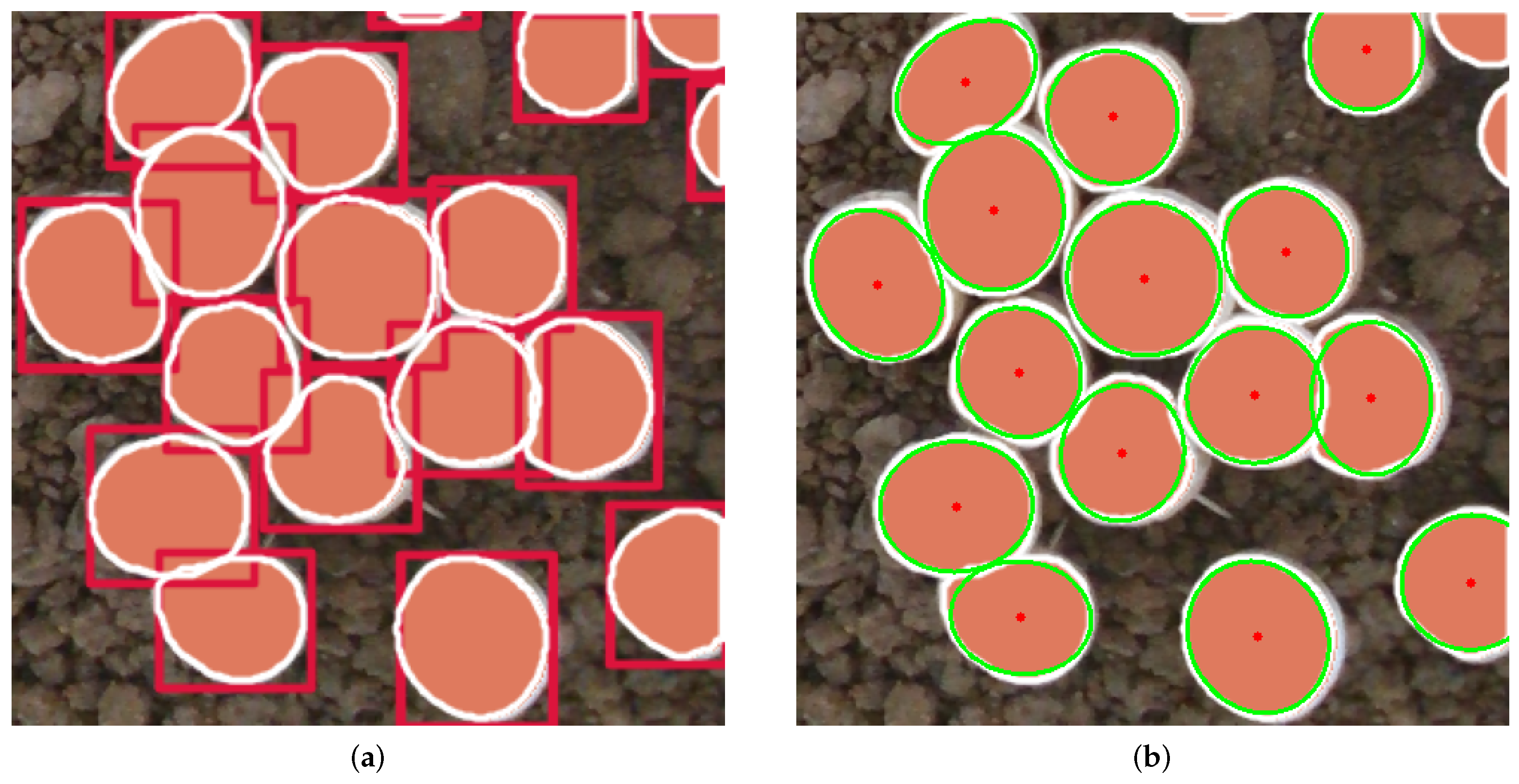
The fitting effect of the location algorithm is shown in Figure 12, where the red box is the bounding box of the algorithm to the segmented target. Figure 12a represents the result of the segmentation algorithm, serving as the input to the localization algorithm. Figure 12b displays the final output of the localization algorithm, where the green ellipses demonstrate a high degree of fitting to the contours of the A. bisporus, thereby yielding precise picking point estimations marked by red dots. It can be demonstrated that the algorithm accurately fits and locates the A. bisporus.
Additionally, the experiment involved 15 samples of A. bisporus. After segmentation using the improved RTMDet-Ins algorithm, the manually annotated centers of A. bisporus were used as reference points for error evaluation. A comparison was made between the average errors of the least squares ellipse fitting localization algorithm and the traditional Hough circle fitting localization.
To more accurately evaluate the deviation of the calculated A. bisporus center, we introduced the Localization Error Rate (LER) [13] as the evaluation metric, expressed as follows:
LER = c m c a w + r m r a h × 100 %
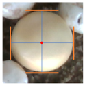
where c m and r m represent the row and column coordinates of the manually determined center position of A. bisporus, and c a and r a represent the row and column coordinates of the algorithmically calculated center position. The values w = 1856 and h = 640 represent the width and height of the panoramic view containing the tested A. bisporus. The smaller the value of LER, the more accurate the positioning result. An example of LER calculation is shown in Table 4. The LER results of least square ellipse fitting and traditional Hough circle transform fitting are shown in Table 5.
The experimental results show that the traditional Hough circle fitting localization algorithm successfully fitted all 15 samples, resulting in a mean LER of 0.52% after statistical analysis of the fitted results. In comparison, the ellipse fitting localization algorithm demonstrated superior performance. It also successfully delineated the contours of all A. bisporus samples, achieving a mean LER accuracy of 0.31%. The least squares ellipse fitting method reduced the absolute LER value by 0.21% compared to the Hough circle fitting algorithm. In summary, in complex scenarios, the least squares ellipse fitting method achieves higher accuracy in A. bisporus localization.

4. Conclusions

This study proposed a segmentation and localization algorithm for A. bisporus based on the improved RTMDet-Ins model. To enhance the algorithm’s ability to extract features from small targets and address the challenge of accurately segmenting A. bisporus in complex environments, our method builds upon the RTMDet-Ins instance segmentation network, incorporating the SimAM global attention mechanism and the lightweight feature fusion module SPD-PAFPN. The improved RTMDet-Ins algorithm reduces parameter count by 4.63% and decreases single-image computation time to 25.38 ms. In the A. bisporus test set, the AP50 reaches 98.50%, representing an improvement in detection accuracy and time efficiency compared to the original model. To further validate the algorithm’s superiority, we compared our method with other classical segmentation networks using data collected by harvesting robots. Experimental results demonstrate that the improved RTMDet-Ins algorithm achieves a detection accuracy 98.64%, surpassing SOLOv2, CondInst, and traditional watershed algorithms. These findings indicate that the improved RTMDet-Ins instance segmentation algorithm can provide real-time, high-precision distribution information of A. bisporus for harvesting robots.
Secondly, a low-cost image stitching method based on the w N C C stitching algorithm with disparity correction is applied to generate high-precision panoramic multimodal fused images. The system was tested on 1320 photos to validate the model’s effectiveness. The global stitching error is less than 2 mm within a 1200 mm × 400 mm. range. It provides high-precision panoramic information for subsequent algorithms.
The experimental results indicate that the method proposed in this paper exhibits superior segmentation and localization accuracy in complex harvesting environments. This can provide more precise and efficient visual perception for A. bisporus harvesting robots.
Although the method proposed in this paper has achieved satisfactory results in the scenarios of the collected dataset, differences in specific factory conditions, such as layer height and mushroom bed size, lead to significant deviations in captured images. This makes it challenging for directly transferred algorithms to achieve ideal results. Therefore, it is necessary to reacquire datasets and conduct annotation and training, incurring additional costs. Additionally, this design adopts an intermittent pause approach for image acquisition to ensure image capture quality, reducing the robot’s overall operation efficiency. Therefore, future research will focus on improving the quality of images captured while in motion and enhancing the model’s generalization ability, aiming to enhance efficiency further and reduce operational costs.

Author Contributions

Conceptualization, C.S. and C.Z. (Changsheng Zhu); methodology, C.S., C.Z. (Changsheng Zhu) and Y.M.; software, Y.M., X.R. and J.N.; validation, C.S., C.Z. (Changsheng Zhu), C.Z. (Chun Zhang), J.Y. and Y.M.; formal analysis, C.S., C.Z. (Chun Zhang), J.Y., Y.M. and X.R.; investigation, C.S., Y.M. and X.R.; resources, C.S. and J.Y.; data curation, Y.M., J.N. and X.R.; writing—original draft preparation, C.S., C.Z. (Changsheng Zhu), Y.M., J.N. and X.R.; writing—review and editing, C.S., C.Z. (Chun Zhang), C.Z. (Changsheng Zhu), Y.M., J.N. and J.Y.; visualization, Y.M. and J.N.; supervision, C.S., C.Z. (Chun Zhang), C.Z. (Changsheng Zhu) and J.Y. All authors have read and agreed to the published version of the manuscript.

Funding

This research was funded by the Shandong Province Science and Technology SMEs Innovation Capability Enhancement Project (No. 2023TATSGC051 and No. 2023TATSGC014).

Institutional Review Board Statement

Not applicable.

Data Availability Statement

The data presented in this study are available on demand from the corresponding author at ([email protected]).

Conflicts of Interest

The author declares no conflicts of interest.

References

  1. Sławińska, A.; Jabłońska-Ryś, E.; Gustaw, W. Physico-Chemical, Sensory, and Nutritional Properties of Shortbread Cookies Enriched with Agaricus bisporus and Pleurotus ostreatus Powders. Appl. Sci. 2024, 14, 1938. [Google Scholar] [CrossRef]
  2. Iqbal, T.; Sohaib, M.; Iqbal, S.; Rehman, H. Exploring Therapeutic Potential of Pleurotus ostreatus and Agaricus bisporus Mushrooms against Hyperlipidemia and Oxidative Stress Using Animal Model. Foods 2024, 13, 709. [Google Scholar] [CrossRef] [PubMed]
  3. Li, Y.; Pan, B.; Wan, Y. Research on the application and future development of visual recognition in modern agriculture. In Proceedings of the 2023 International Conference on Data Science, Advanced Algorithm and Intelligent Computing (DAI 2023); Atlantis Press: Amsterdam, The Netherlands, 2024; pp. 25–35. [Google Scholar]
  4. Lu, C.P.; Liaw, J.J.; Wu, T.C.; Hung, T.F. Development of a mushroom growth measurement system applying deep learning for image recognition. Agronomy 2019, 9, 32. [Google Scholar] [CrossRef]
  5. Wee, B.S.; Chin, C.S.; Sharma, A. Survey of Mushroom Harvesting Agricultural Robots and Systems Design. IEEE Trans. AgriFood Electron. 2024, 2, 59–80. [Google Scholar] [CrossRef]
  6. Li, J.; Feng, Q.; Ru, M.; Sun, J.; Guo, X.; Zheng, W. Design of Shiitake Mushroom Robotic Picking Grasper: Considering Stipe Compressive Stress Relaxation. Machines 2024, 12, 241. [Google Scholar] [CrossRef]
  7. Liu, J.; Liu, Z. The Vision-Based Target Recognition, Localization, and Control for Harvesting Robots: A Review. Int. J. Precis. Eng. Manuf. 2024, 25, 409–428. [Google Scholar] [CrossRef]
  8. Eastwood, D.C.; Herman, B.; Noble, R.; Dobrovin-Pennington, A.; Sreenivasaprasad, S.; Burton, K.S. Environmental regulation of reproductive phase change in Agaricus bisporus by 1-octen-3-ol, temperature and CO2. Fungal Genet. Biol. 2013, 55, 54–66. [Google Scholar] [CrossRef] [PubMed]
  9. Reed, J.; Miles, S.; Butler, J.; Baldwin, M.; Noble, R. AE—Automation and emerging technologies: Automatic mushroom harvester development. J. Agric. Eng. Res. 2001, 78, 15–23. [Google Scholar] [CrossRef]
  10. Yu, G.; Luo, J.; Zhao, Y. Region marking technique based on sequential scan and segmentation method of mushroom images. Trans. Chin. Soc. Agric. Eng. (Trans. CSAE) 2006, 22, 139–142. [Google Scholar]
  11. Zhou, R.; Chang, Z.; Sun, Y.; Fan, P.; Tan, C. A Novel Watershed Image Segmentation Algorithm Based on Quantum Inspired Morphology. J. Inf. Comput. Sci. 2015, 12, 4331–4338. [Google Scholar] [CrossRef]
  12. Chen, C.; Yi, S.; Mao, J.; Wang, F.; Zhang, B.; Du, F. A Novel Segmentation Recognition Algorithm of Agaricus bisporus Based on Morphology and Iterative Marker-Controlled Watershed Transform. Agronomy 2023, 13, 347. [Google Scholar] [CrossRef]
  13. Yang, S.; Ni, B.; Du, W.; Yu, T. Research on an improved segmentation recognition algorithm of overlapping Agaricus bisporus. Sensors 2022, 22, 3946. [Google Scholar] [CrossRef] [PubMed]
  14. Baisa, N.L.; Al-Diri, B. Mushrooms detection, localization and 3d pose estimation using rgb-d sensor for robotic-picking applications. arXiv 2022, arXiv:2201.02837. [Google Scholar]
  15. Shi, C.; Nie, J.; Mo, Y.; Zhang, C.; Zhu, C.; Zang, X. High precision scene stitching and recognition of agaricus bisporus based on depth camera. In Proceedings of the Third International Computing Imaging Conference (CITA 2023), Sydney, Australia, 1–3 June 2023; SPIE: Bellingham, WA, USA, 2023; Volume 12921, pp. 1001–1006. [Google Scholar]
  16. Tian, Z.; Shen, C.; Chen, H. Conditional convolutions for instance segmentation. In Proceedings of the Computer Vision–ECCV 2020: 16th European Conference, Glasgow, UK, 23–28 August 2020; Proceedings, Part I 16. Springer: Berlin/Heidelberg, Germany, 2020; pp. 282–298. [Google Scholar]
  17. Wang, X.; Zhang, R.; Kong, T.; Li, L.; Shen, C. Solov2: Dynamic and fast instance segmentation. Adv. Neural Inf. Process. Syst. 2020, 33, 17721–17732. [Google Scholar]
  18. Zhong, M.; Han, R.; Liu, Y.; Huang, B.; Chai, X.; Liu, Y. Development, integration, and field evaluation of an autonomous Agaricus bisporus picking robot. Comput. Electron. Agric. 2024, 220, 108871. [Google Scholar] [CrossRef]
  19. Briechle, K.; Hanebeck, U.D. Template matching using fast normalized cross correlation. In Proceedings of the Optical Pattern Recognition XII, Orlando, FL, USA, 16–20 April 2001; SPIE: Bellingham, WA, USA, 2001; Volume 4387, pp. 95–102. [Google Scholar]
  20. Lyu, C.; Zhang, W.; Huang, H.; Zhou, Y.; Wang, Y.; Liu, Y.; Zhang, S.; Chen, K. Rtmdet: An empirical study of designing real-time object detectors. arXiv 2022, arXiv:2212.07784. [Google Scholar]
  21. Yang, L.; Zhang, R.Y.; Li, L.; Xie, X. Simam: A simple, parameter-free attention module for convolutional neural networks. In Proceedings of the International Conference on Machine Learning, Virtual, 18–24 July 2021; PMLR: New York, NY, USA, 2021; pp. 11863–11874. [Google Scholar]
  22. Chollet, F. Xception: Deep learning with depthwise separable convolutions. In Proceedings of the IEEE Conference on Computer Vision and Pattern Recognition, Honolulu, HI, USA, 21–16 July 2017; pp. 1251–1258. [Google Scholar]
  23. Lin, T.Y.; Dollár, P.; Girshick, R.; He, K.; Hariharan, B.; Belongie, S. Feature pyramid networks for object detection. In Proceedings of the IEEE Conference on Computer Vision and Pattern Recognition, Honolulu, HI, USA, 21–16 July 2017; pp. 2117–2125. [Google Scholar]
  24. Liu, S.; Qi, L.; Qin, H.; Shi, J.; Jia, J. Path aggregation network for instance segmentation. In Proceedings of the IEEE Conference on Computer Vision and Pattern Recognition, Salt Lake City, UT, USA, 18–23 June 2018; pp. 8759–8768. [Google Scholar]
  25. Sunkara, R.; Luo, T. No more strided convolutions or pooling: A new CNN building block for low-resolution images and small objects. In Proceedings of the Joint European Conference on Machine Learning and Knowledge Discovery in Databases, Grenoble, France, 19–23 September 2022; Springer: Berlin/Heidelberg, Germany, 2022; pp. 443–459. [Google Scholar]
  26. Fausto Milletari, N.; V-Net, A.S.A. Fully Convolutional Neural Networks for Volumetric Medical Image Segmentation. Available online: https://arxiv.org/abs/1606.04797 (accessed on 2 January 2024).
  27. Wang, C.Y.; Liao, H.Y.M.; Wu, Y.H.; Chen, P.Y.; Hsieh, J.W.; Yeh, I.H. CSPNet: A new backbone that can enhance learning capability of CNN. In Proceedings of the IEEE/CVF Conference on Computer Vision and Pattern Recognition Workshops, Seattle, WA, USA, 14–19 June 2020; pp. 390–391. [Google Scholar]
  28. Sajjadi, M.S.; Vemulapalli, R.; Brown, M. Frame-recurrent video super-resolution. In Proceedings of the IEEE Conference on Computer Vision and pattern Recognition, Salt Lake City, UT, USA, 18–23 June 2018; pp. 6626–6634. [Google Scholar]
  29. Fitzgibbon, A.; Pilu, M.; Fisher, R.B. Direct least square fitting of ellipses. IEEE Trans. Pattern Anal. Mach. Intell. 1999, 21, 476–480. [Google Scholar] [CrossRef]
Figure 1. The A. bisporus picking robot. (a) Movement flow of the visual module; (b) platform design; (c) physical machine.
Agriculture 14 00735 g001
Figure 2. Algorithm processing flow.
Agriculture 14 00735 g002
Figure 3. Parallax principle. (a) Generation process; (b) correction process.
Agriculture 14 00735 g003
Figure 4. Parallax correction results. (a) Original image; (b) parallax correction results after background separation; (c) positional relationship of A. bisporus before and after parallax correction.
Agriculture 14 00735 g004
Figure 5. Local deep images and color images of allocation and fusion results. (a) Deep energy map; (b) Color image; (c) Fusion image after the standard.
Agriculture 14 00735 g005
Figure 6. w N C C Template matching algorithm principle. (a) 3D curved image; (b) gray image.
Agriculture 14 00735 g006
Figure 7. Panorama depth map synthesis results.
Agriculture 14 00735 g007
Figure 8. Improved RTMDet-Ins network architecture.
Agriculture 14 00735 g008
Figure 9. CSP-Sim Module Structure.
Agriculture 14 00735 g009
Figure 10. SPD-CONV process.
Agriculture 14 00735 g010
Figure 11. Segmentation results. (a) Original image; (b) RTMDet-Ins; (c) our method.
Agriculture 14 00735 g011
Figure 12. Localization results. (a) Origin image; (b) Fitting result.
Agriculture 14 00735 g012
Table 1. Panoramic stitching error results.
Sample IDNo. 1No. 2No. 3No. 4No. 5No. 6No. 7No. 8No. 9No. 10
Panoramic Stitching Errors
after Disparity Correction/mm
1.8551.9322.0211.9032.0291.8921.9231.9292.0041.969
Panoramic Stitching Errors
without Correction/mm
15.23617.76818.23416.24618.67519.02315.91216.82418.89717.932
Table 2. Improved point ablation experiment.
MethodsSimAMSPD-ConvParams (M)FLOPs (G)Running Time (ms)AP50 (%)AP75 (%)
RTMDet-Ins 5.6111.8726.2696.5093.48
RTMDet-Ins + SimAM 5.4611.8725.7397.9195.73
RTMDet-Ins + SPD-Conv 5.5310.7426.1596.9394.20
Improved RTMDet-Ins5.3510.7425.3898.5096.10
Table 3. Segmentation results.
Sample IDNumberImproved RTMDet-InsSOLOv2CondInstWatershed
Correct NumberCorrect Rate (%)Correct NumberCorrect Rate (%)Correct NumberCorrect Rate (%)Correct NumberCorrect Rate (%)
No. 13131100.0031100.0031100.002993.55
No. 24141100.003995.1241100.003892.68
No. 3383797.373592.113697.743489.47
No. 43333100.0033100.0033100.003090.91
No. 5333296.973296.973296.973090.91
No. 6444397.734193.184193.183988.64
No. 73838100.003797.373694.743694.74
No. 82929100.002896.552896.552896.55
No. 9525198.085198.085096.154892.31
No. 10535196.235094.345196.234992.45
Average Correct Rate98.64%96.37%96.86%92.22%
Table 4. Example of LER calculation.
Manual PositiomngLeast-Squares Ellipse FittingHough Transform Circle Fitting
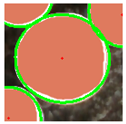
Positioning exampleAgriculture 14 00735 i001Agriculture 14 00735 i002Agriculture 14 00735 i003
Coordinate(523, 235)(523, 230)(522, 228)
LER00.78%1.15%
Table 5. Localization results.
Sample IDManualLeast-Squares Ellipse FittingHough Transform Circle Fitting
Algorithm LocationLER (%)Algorithm LocationLER (%)
No. 1(210, 71)(211, 72)0.21%(208, 69)0.42%
No. 2(378, 261)(380, 261)0.11%(380, 257)0.73%
No. 3(104, 338)(102, 335)0.58%(102, 340)0.42%
No. 4(300, 420)(303, 424)0.79%(303, 423)0.63%
No. 5(233, 178)(235, 178)0.11%(233, 174)0.63%
No. 6(157, 409)(152, 406)0.74%(155, 412)0.58%
No. 7(215, 295)(218, 298)0.63%(213, 292)0.58%
No. 8(303, 255)(308, 254)0.43%(306, 251)0.79%
No. 9(61, 183)(61, 182)0.16%(57, 183)0.22%
No. 10(129, 133)(129, 132)0.16%(128, 130)0.52%
No. 11(328, 163)(329, 164)0.21%(325, 159)0.79%
No. 12(146, 243)(146, 242)0.16%(148, 240)0.58%
No. 13(445, 384)(446, 383)0.21%(441, 387)0.68%
No. 14(117, 44)(118, 44)0.05%(118, 45)0.21%
No. 15(381, 29)(380, 29)0.05%(379, 28)0.26%
mean LER0.31%0.52%
Disclaimer/Publisher’s Note: The statements, opinions and data contained in all publications are solely those of the individual author(s) and contributor(s) and not of MDPI and/or the editor(s). MDPI and/or the editor(s) disclaim responsibility for any injury to people or property resulting from any ideas, methods, instructions or products referred to in the content.