Abstract
This study centered around the practical problem that there is no machine available for deep planting with large holes in hilly and mountainous areas of China. According to the principle of spiral lifting, a conical, double-spiral hole-forming machine was innovatively designed. The structural design and parameter calculation were completed. By discrete-element-method (DEM) simulation, the optimal lead and rotation speed of the hole former were obtained, and the hole-forming mechanisms of soil cutting, soil lifting, soil discharging, soil extruding, and soil returning were further revealed. The field test results indicated that the prototype had the advantages of convenient operation and good performance, and the formed holes met the agronomic requirements, with a qualification rate of 88.5%. In addition, it was found that the soil moisture content has a great influence on the formation of holes. Under the condition of low moisture content, the residence time at the bottom of a hole should be appropriately increased to improve the qualification rate of the holes formed. Our research results provided theoretical guidance and technical support for the design, optimization, popularization, and application of a hole-forming machine for deep planting with large holes (DPLH).
1. Introduction
In the 1990s, the transplantation of seedlings under plastic film was tested in Northeast and Northwest China for the first time. Compared with the previous planting methods, the transplanting date was 10–15 days earlier, which achieved the goal of increasing production and income, so it was popularized throughout the country [1]. Deep planting with large holes (DPLH) is a type of transplanting technology under film, which not only has the advantages of shortening the recovery stage and enhancing the survival rate of transplanting but also can improve the yield and quality of crops in areas with spring drought and can realize increases in production and income [2]. At present, DPLH has become the main transplanting method of tobacco, pepper, and other crops in areas with spring drought and little rain in southwest China [3].
The technique of DPLH was developed earlier, but the development of matching machines and the theoretical research on transplanting larger holes occurred later. During the development phase of hole-forming machines, Jiahong and colleagues designed a compound machine that achieved the task of forming and transplanting holes. The field test demonstrated that the machine had high working efficiency, and the depth and size of the formed holes met the agronomic requirements [4]. Fei et al. designed and developed a small planter in a large hole. Their experimental observations showed that the hole depth was 141 mm, the hole diameter was 306 mm, and the qualification rate of hole formation was high [5]. Although the research and development of the above-mentioned hole-forming machine for DPLH has, to some extent, solved the practical problem that there are no appropriate machines available in some areas, its popularization and application are limited because of its cumbersome and complicated structure. In theoretical research of transplanting holes and the structural design of a hole-forming machine, Xiang et al. designed a new rapeseed transplanting machine. They analyzed the motion mechanism of a pure rolling-type machine to derive motion parametric equations for the hole-forming machine. MATLAB 2020b was employed to generate theoretical contour lines and outline drawings of the transplanting hole. CATIA was then utilized for simulation analysis to obtain the contour curve of the transplanting hole, and fitting as well as simulation were carried out to verify its structure and motion parameters [6,7]. Kaisu et al. studied the theory of the soil lifting of auger bits of diggers and deduced the general formula for calculating the critical speed of the bit. They found that the critical speed of the drill bit was also related to soil viscosity, which was increased by about 1.2 times for the digger used in cohesive soil [8]. Wei et al. researched the hole-forming operation mode of rape transplanting, the structural optimization of the hole former, and the operation performance of the hole-forming machine. Through this approach, they optimized the hole-forming mode and the operation parameters of the hole former, improved the hole-forming operation, and provided technical support for future research on the interaction between the hole-forming mechanism and the soil [9,10,11]. Han, C. et al. conducted a parameter optimization design and experimental study on the hole former of a watermelon pot seedling planter. Their experimental results indicated that when the diameter of the small end of the hole former was 60 mm and the theoretical hole-forming depth was 65 mm, the hole shape was conducive to transplanting watermelon seedlings raised on a compacted substrate [12]. To sum up, researchers have mainly investigated the theory of hole digging for planting trees, the hole-forming method of soil picking and soil extruding for transplanting seedlings, and the structural optimization of hole formers. However, there are few reports regarding the device and theory of hole formation in DPLH.
In this research, a hole-forming machine suitable for hilly and mountainous areas was designed for DPLH, and the parameters were designed and optimized through theoretical analysis and discrete-element-method (DEM) simulation, and the hole-forming mechanism was revealed. Our research results provided theoretical guidance and technical support for the optimal design of a hole-forming machine for DPLH.
2. Materials and Methods
2.1. DPLH Technique
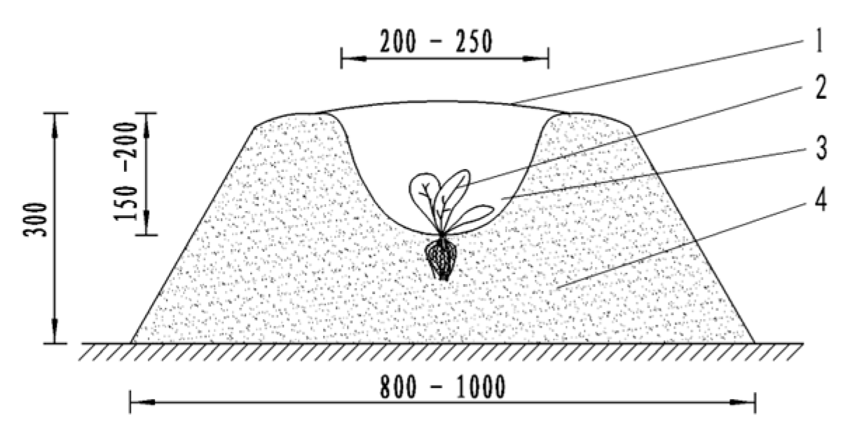
DPLH belongs to the mode of transplanting under film (Figure 1), which is one of the transplanting techniques on ridge surfaces. Its technical characteristics are as follows: first, digging a hole on a ridge, transplanting the seedling into the hole after applying base fertilizer, then covering the ridge with plastic film, cutting the film in the center of the hole, and pressing the film and cultivating the soil to expose the seedling [13]. Studies have shown that DPLH effectively raised ground temperature, resisted drought and conserved moisture, improved lighting conditions, enhanced soil fertility, reduced pests and diseases, and provided a good growth environment for the early growth of seedlings [14,15]. According to the agronomic requirements, the hole of DPLH was approximately conical, the hole diameter was 200–250 mm, and the hole depth was 150–200 mm.
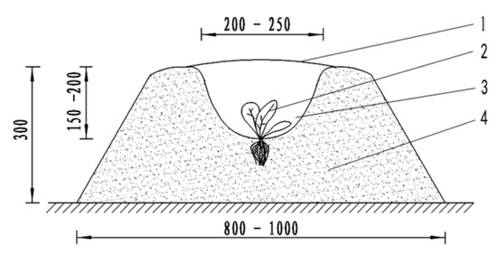
Figure 1.
Diagram of DPLH. 1. Film, 2. seedling, 3. hole, 4. ridge body.
2.2. Design of the Hole-Forming Machine for DPLH
Currently, the traditional method of “manual and hoe” is still widely employed to dig a large hole for DPLH in the vast hilly and mountainous areas of China, which is labor-intensive and inefficient, and the consistency of the hole formation is poor, so it struggles to meet the needs of modern agricultural production. For this reason, based on the landform and soil condition of hilly and mountainous areas and transplanting requirements, our research group developed a backpack large-hole-forming machine for DPLH (Figure 2), which was mostly composed of a gasoline engine, flexible shaft, reducer, hard shaft, spiral hole former, handle, and protective cover [16,17]. The power provided by the gasoline engine, 1, is transmitted to the reducer, 6, through the flexible shaft, 3, and then to the spiral hole former through the hard shaft, 7. In operation, the operator with the engine, 1, on his back operates the handle, 5, to make a large hole for transplanting by the spiral hole former, 9, in the designated positions.
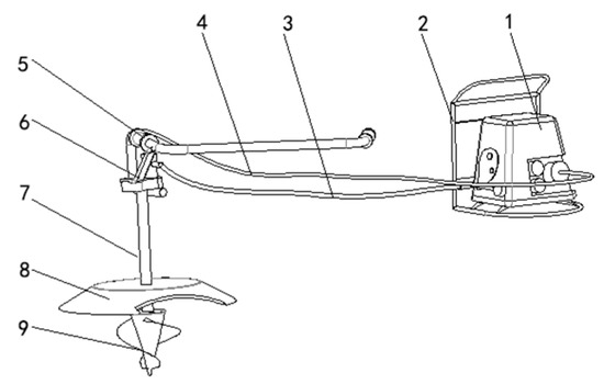
Figure 2.
Structure diagram of the large-hole-forming machine. 1. Gasoline engine, 2. back pad, 3. flexible shaft, 4. clutch control line, 5. handle, 6. reducer, 7. hard shaft, 8. protective cover, 9. spiral hole former.
2.2.1. Design of the Spiral Hole Former
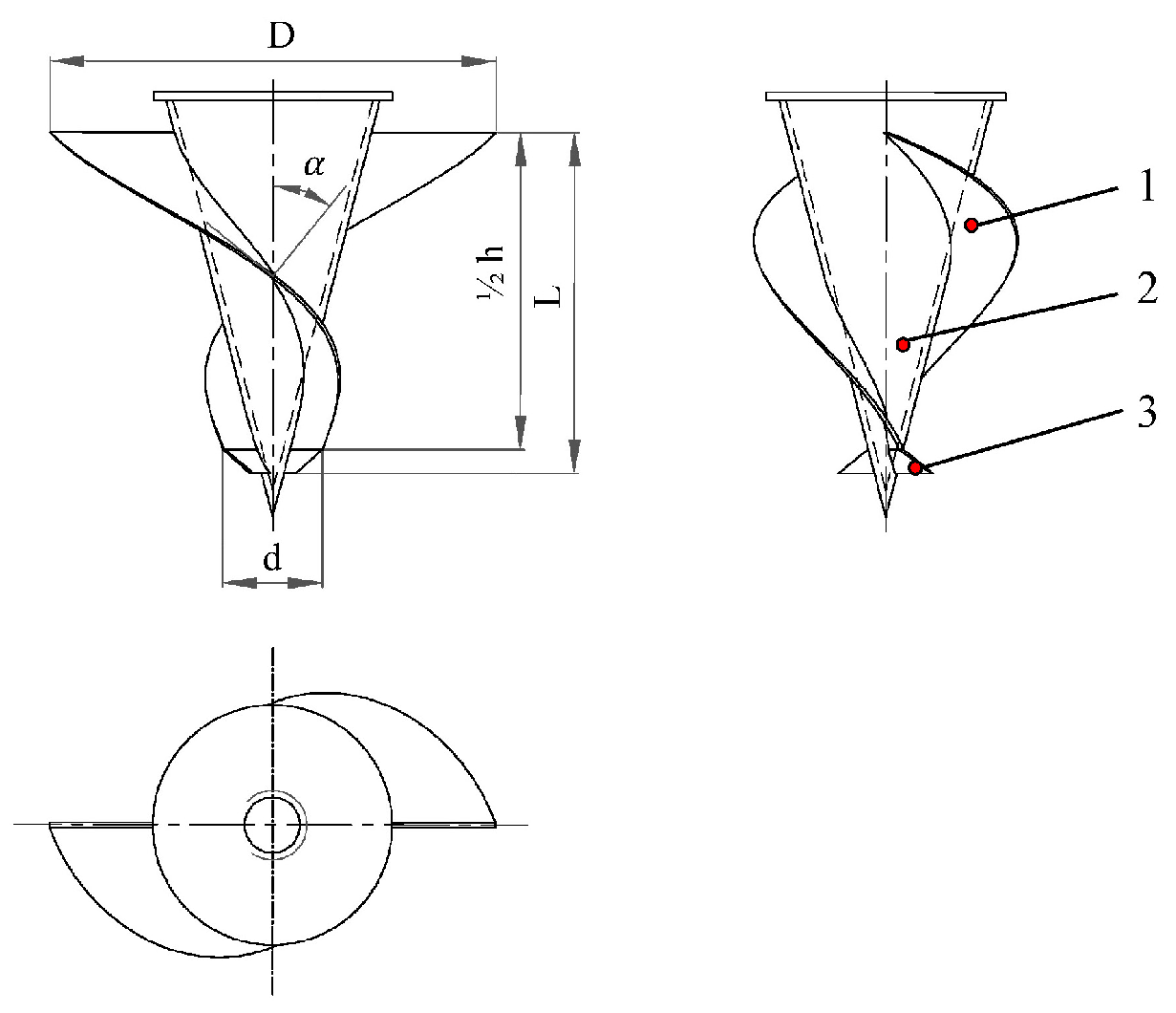
A hole former is a key part of the large-hole-forming machine, and its structure directly affects the quality of hole formation. There are two commonly used methods of hole formation for seedling transplantation: the soil-picking type and soil-extruding type [11]. Considering that the hole diameter is large and the hole depth is deep for DPLH, it struggles to meet the requirements of large hole formation by soil picking or soil extruding. Therefore, the hole former was designed as a conical, double-helix structure [18,19,20] (Figure 3), and the hole former realized the compound hole-forming mode of extruding soil in the lower part and discharging soil in the upper part.
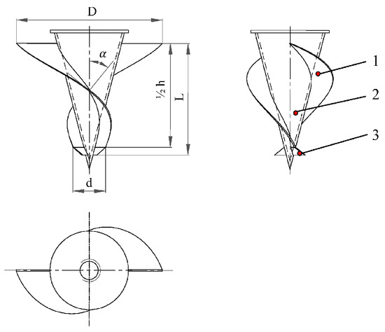
Figure 3.
Structural diagram of the spiral hole former. 1. Spiral blade, 2. conical core, 3. soil cutting blade.
Considering the problem of soil returning to the hole in the process of hole formation, the major diameter of the hole former was calculated according to [21,22], where is the median diameter of the hole (225 mm). The major diameter of the hole former was calculated to be 200 mm, and the minor diameter and the spiral length ( were computed to be 100 mm and 150 mm, respectively.
- (1)
- Determination of helix angle and lead
High transporting efficiency and low power consumption are the main factors that should be considered in the selection of the helix angle. The selection of the helix angle must satisfy the following formula:
where stands for the included angle between the spiral blade and the horizontal ground; represents the friction angle between the soil and helicoid; denotes the included angle between the moving direction of soil particles and the horizontal plane. According to the design experience, the helix angle of an auger bit is generally 10–22° [21]. Based on the relationship between the elevation angle, lead, and diameter of the auger, the following equation was established:
where symbolizes the outer diameter of the spiral, (i.e., the major diameter of the hole former) in mm; indicates spiral pitch in mm. Through calculation, the lead range was estimated to be 110–250 mm.
- (2)
- Determination of feed
The feed per revolution of the hole former was determined according to the soil transportation situation and power, and the feed was calculated based on the following formula:
We considered the hole to be formed on cultivated soil, and the included angle between the spiral blade and the horizontal ground was 1°. We also calculated that the feed was equal to 11 mm.
- (3)
- Primary selection of critical speed of hole former
The rotational speed is an important working parameter of the hole former, which affects the input power, hole-forming efficiency, and the wear of spiral blades. The critical rotational speed of the hole former was calculated using the following formula:
where is the acceleration of gravity; is the average radius of the spiral ; is a dimensionless similarity criterion, that is, the dimensionless motion equation of spiral drill bits with different diameters. Under the same working conditions, if remains unchanged, will remain unchanged. was calculated according to the following formula:
where stands for the friction coefficient between soils. Generally, the of an auger bit is 2.5–4.5 [21], and if it is substituted into Formula (2), the critical speed range of n = 236–425 rpm will be obtained.
- (4)
- Determination of soil cutting front angle and back angle of the blade
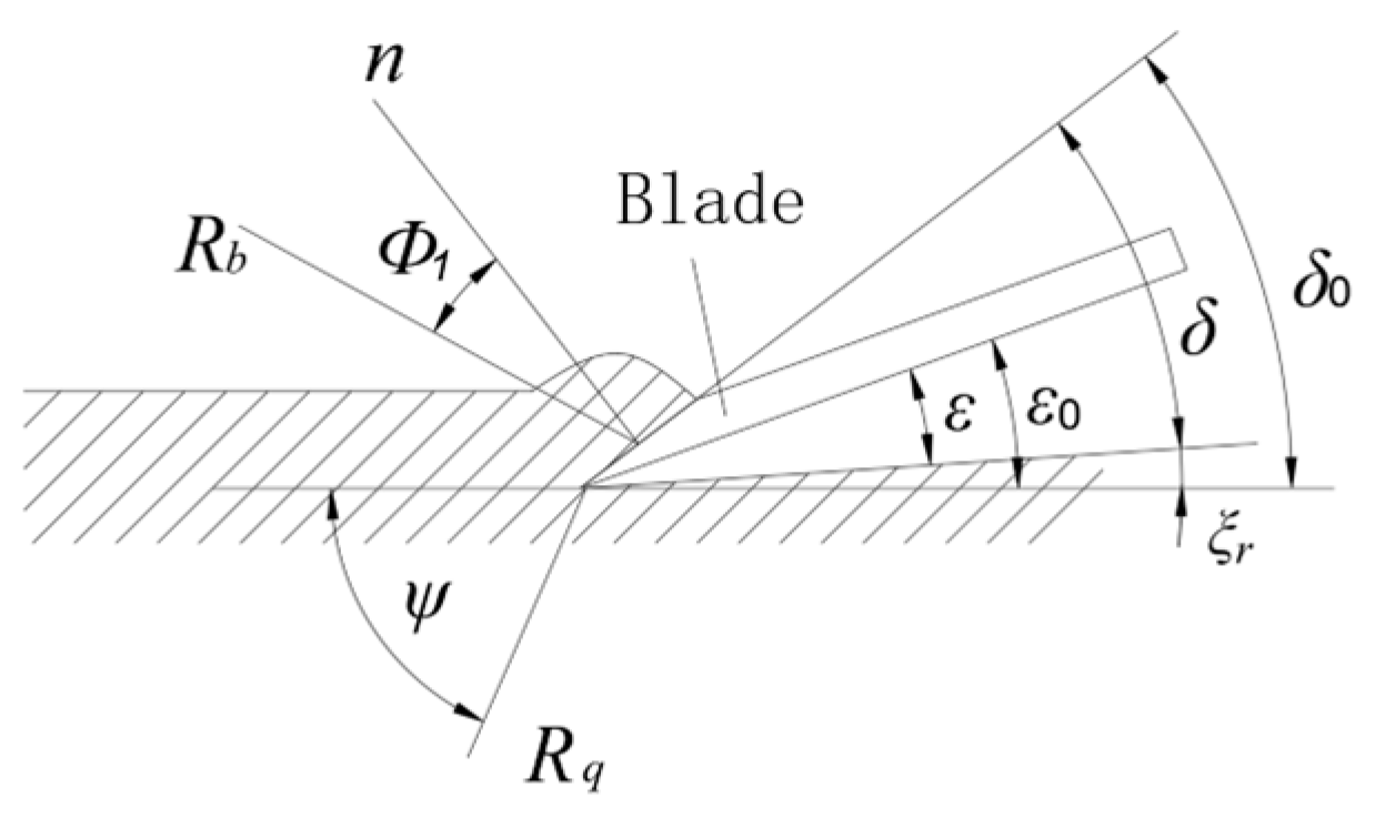
The principle of determining the cutting angle of the blade is that the cutting torque is small, the axial force is small, and the blade has sufficient strength and life. The schematic diagram of blade-cutting soil is shown in Figure 4. The hole former rotates and has axial feed movement simultaneously. Thus, the movement tracks at different radii on the blade are spirals with different rising angles.

Figure 4.
Schematic diagram of blade-cutting soil.
In the process of soil cutting, the actual soil cutting front angle and back angle of the hole former were calculated based on the following formula:
where is the nominal soil cutting front angle of the blade; is the nominal soil cutting back angle of the blade; is the distance from the calculating point to the axis center; and is the included angle between the moving direction of the calculating point and the horizontal plane.
The main parameter design of the hole-forming head is shown in Table 1.

Table 1.
Hole former key parameters.
2.2.2. Three-Dimensional Model of the Spiral Hole Formers
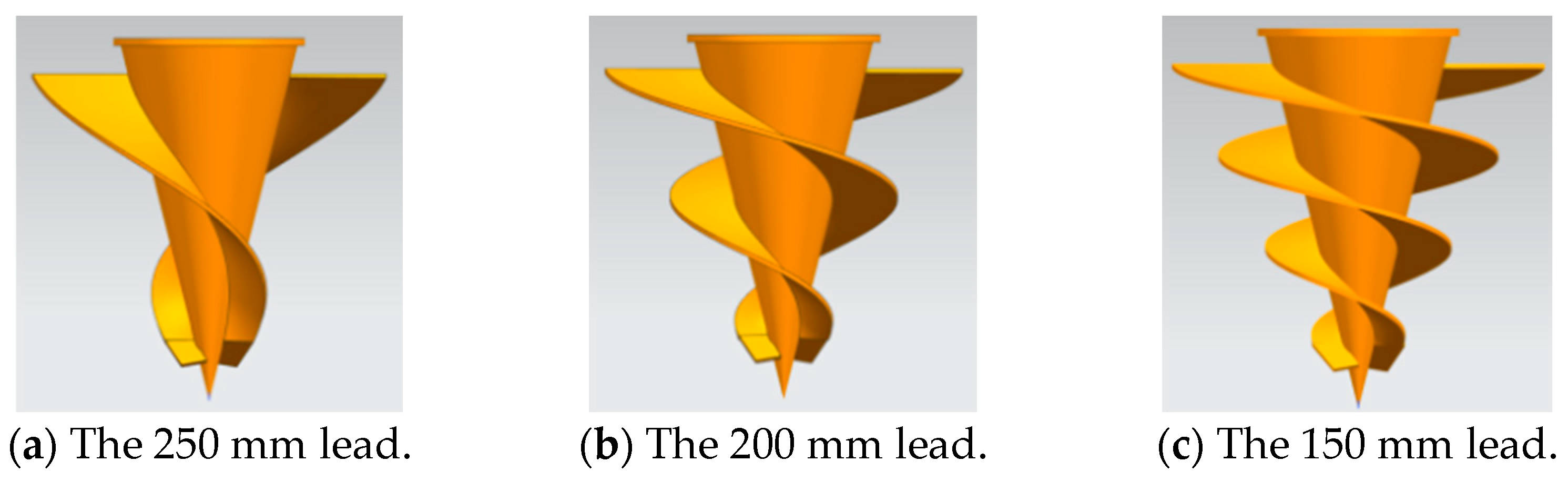
Based on the above-mentioned spiral lead range and spiral length, and referring to the structure of the spiral hole-forming bit of a common tree-planting and digging machine, three hole formers with leads of 150 mm, 200 mm, and 250 mm were designed. Three-dimensional models of three kinds of the spiral hole formers are shown in Figure 5.

Figure 5.
Three-dimensional models of spiral hole formers with different leads.
2.2.3. Calculation of Engine Total Power
The total power of the engine is primarily determined by the cutting power of the blade and the power of lifting soil particles.
The cutting power of the blade was computed according to the following formula:
where represents the number of spiral blades ; denotes the blade resistance coefficient (for soft soil: = 1800–2400 N/m) [21]; signifies the included angle between soil resistance acting on the blade edge and the horizontal plane (for soft soil: = 30°–35°; symbolizes the resistance coefficient of soil deformation (for soft soil: = (1.2–1.7) × 105 Pa); and stands for the friction angle between the soil and 65Mn steel ( = 15°–40°).
The power of lifting soil particles is related to the flow rate of soil particles per unit of time, which chiefly includes the power consumed by the increase in the potential energy and kinetic energy of soil particles and the friction between the soil and helical surface. The power of lifting soil particles was calculated using the following formula:
The power consumed by increasing the potential energy of soil particles was computed by the following formula:
The power consumed by increasing the kinetic energy of soil particles was calculated using the following formula:
The friction power between the conveying soil particles and the helical surface was computed based on the following formula:
The soil particle flow per unit of time was calculated according to the following formula:
where is the coefficient of soil porosity, generally = 1.2–1.6; is the bulk density of loose soil, generally = 1000–1300 kg/m3.
Therefore, the total engine power is computed by the following formula:
where is the power reserve coefficient, usually = 1.3–1.5; is the transmission efficiency of the hole-forming machine, usually = 0.9–0.95.
2.3. DEM Simulation
DEM is a numerical analysis method commonly used to solve and analyze the motion law of discrete systems. At present, DEM has become an effective method to simulate and analyze the interaction between soil-engaging parts of agricultural machinery and soil, and many scholars have utilized DEM to investigate soil-engaging problems such as cultivating, planting, and hole formation [23,24,25,26,27,28]. We optimized the working speed and lead of the hole former with the help of EDEM 2020 simulation software and explored its hole-forming mechanism.
The three-dimensional model of the hole former was established using UG NX 8.5 software and saved in IGS file format, and then, it was imported into EDEM 2020 software. A cuboid-shaped soil bin with the size of 600 mm × 600 mm × 250 mm (length × width × height) was established, and the parameters of the soil particles factory were set as follows: the size was set to random, the particle model selected a single spherical particle with a radius of 3 mm as the benchmark, the radius of randomly generated particles was set to 0.5–2 times, the position was set to random, the velocity was set to 3 m/s, the direction was along the negative direction of the Z axis, the factory type was set to dynamic, and the total number of generated particles was 175,000. The soil model was divided into five layers, each with a height of 50 mm, and Hertz–Mindlin with JKR was selected as the contact model between soil particles. The Hertz–Mindlin (no-slip) model without sliding contact between soil particles and the hole former was selected. The simulation model is shown in Figure 6.
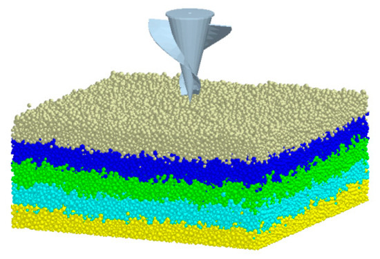
Figure 6.
DEM simulation model.
In the simulation modeling, referring to the calibration test results of our research group regarding yellow clay soil particles, 65Mn steel, and contact parameters [29], the DEM simulation parameters were set as shown in Table 2. In the simulation analysis, the particle generation time was 1 s, both the descending and ascending times of the hole former were 2 s, and the time step was 0.02 s.
Table 2.
Material parameters and contact parameters of DEM simulation.
2.4. Field Test
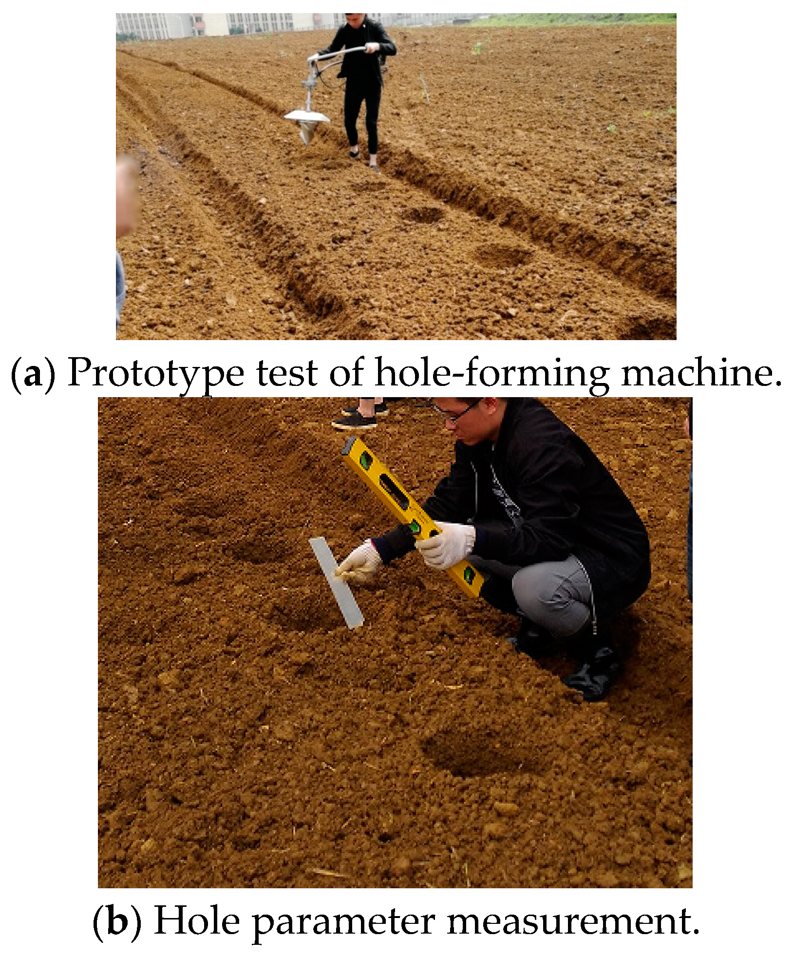
To test the working performance of the prototype of the hole-forming machine for DPLH, a field experiment was carried out in Caohai Science and Technology Park, Weining County, Bijie City, China, on 5 April 2023. The test equipment included the hole-forming machine (equipped with an air-cooled gasoline engine with a power of 0.8 kW), level meter, steel ruler, stopwatch, and pull wire. The experimental plot was rototilled twice and ridged, the ridge height was 200–250 mm, and the ridge surface width was 300–350 mm.
In order to obtain the particle size and moisture content of the soil in the test site, soil samples were taken at three locations every 20 m on the test ridge, and the soil moisture content was 13.8% by the drying method. The tested soil body was screened with a standard inspection screen to obtain the distribution of particle size and proportion of soil and sand and gravel, as shown in Table 3.
Table 3.
Standard screening data for soil sieves.
The field test is shown in Figure 7. Before the test, every 500 mm was marked with lime. A total of 100 large holes were made continuously in the same plot; the test time was recorded with a stopwatch; the hole diameter and depth were measured; and finally, the average value, qualification rate, and the work efficiency were calculated.
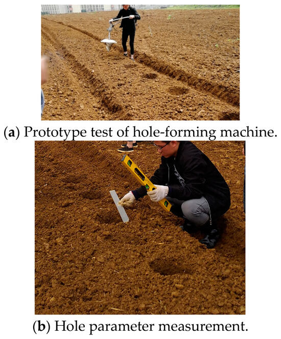
Figure 7.
Images of test process.
3. Results and Discussion
3.1. Parameter Optimization Based on DEM
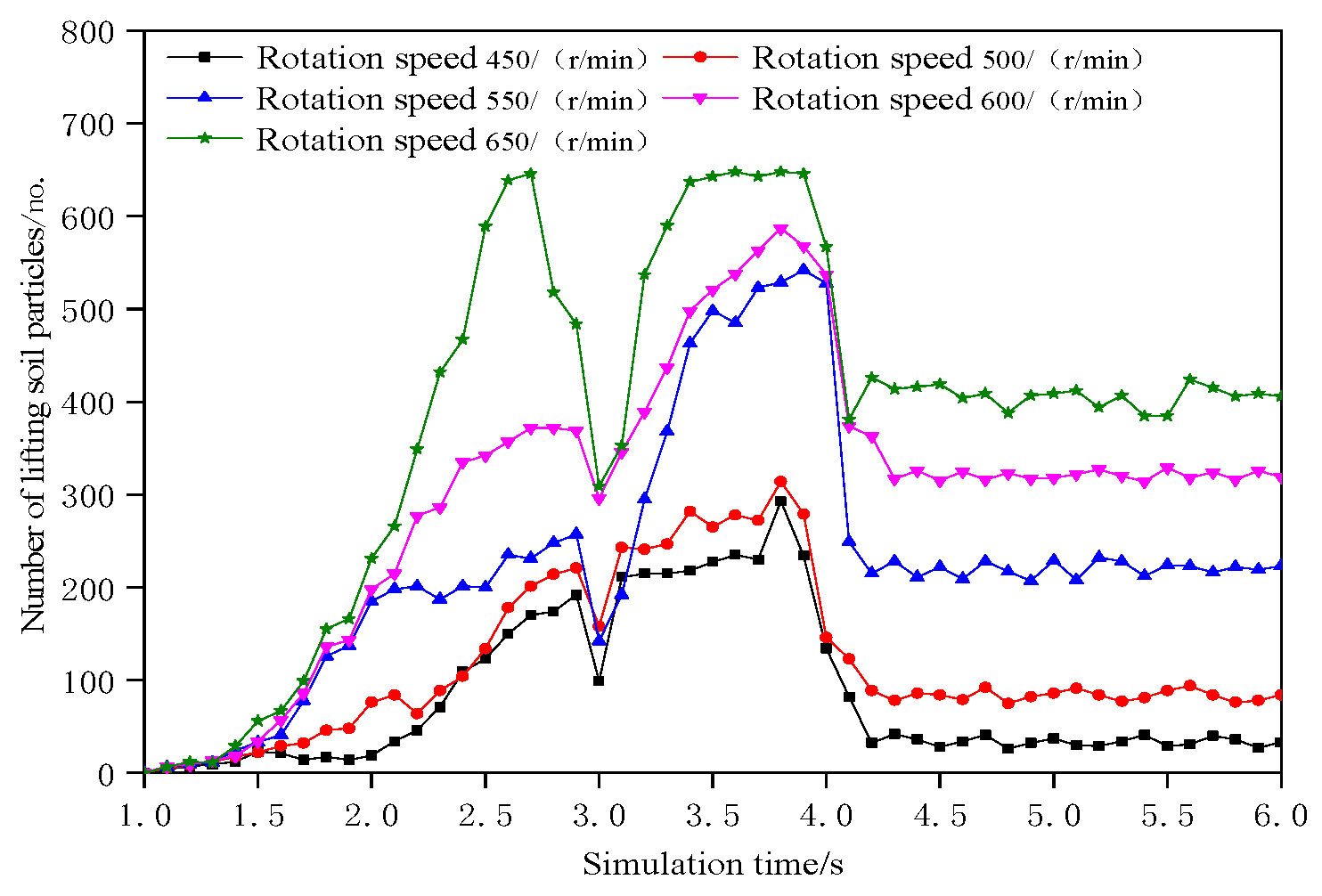
According to Section 2.2.1, the critical rotation speed in cohesive soil was enhanced by 1.2 times [8]. Thus, the simulation analysis was performed using the following conditions: the rotation speed of the hole former was set to 450 rpm, 500 rpm, 550 rpm, 600 rpm, and 650 rpm; the lead was 200 mm; and the total simulation time was set to 6 s, in which the residence periods at the bottom of the hole were 1 s. The number of soil particles lifted by the hole former and the working resistance are shown as line charts in Figure 8 and Figure 9.

Figure 8.
Variation in the number of soil particles lifted by the hole former under different rotation speeds.
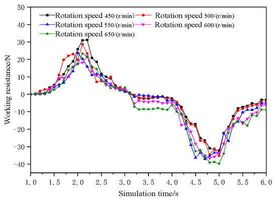
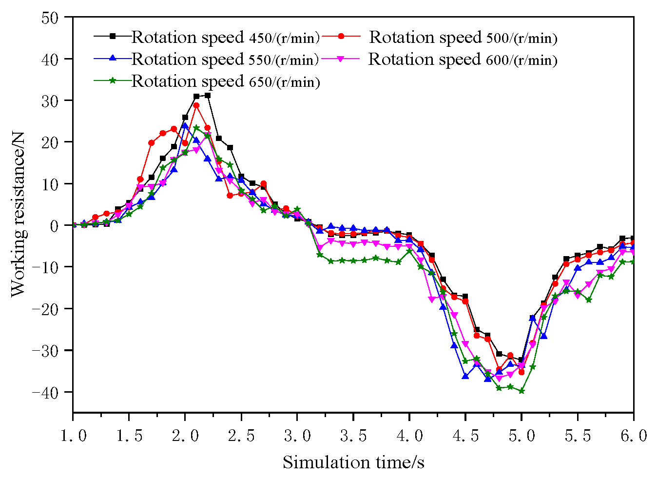
Figure 9.
Variation in the working resistance in the hole former under different rotation speeds.
Figure 8 shows that the number of lifted soil particles increased with the increase in rotation speed at all rotation speeds. Moreover, during the descending and staying periods, the number of lifted soil particles first increased and then decreased; however, it tended to be stable in the ascending period. Figure 9 shows that the working resistance of the hole former increased at the beginning and then decreased during the descending and ascending periods, with the maximum resistance occurring when the rotation speed was 450 rpm during the descending period and when it was 650 rpm during the ascending period. The overall working resistance tended to be stable during the residence periods, and its value was close to zero. Based on the comprehensive consideration of lifting capacity and decreasing working resistance, the working speed of the hole former was initially determined to be 500–600 rpm.
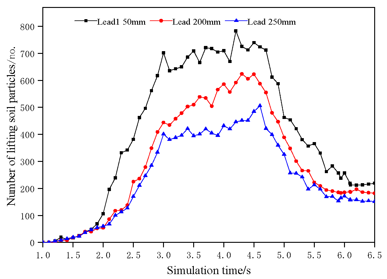
Three hole formers with leads of 150 mm, 200 mm, and 250 mm (Figure 5) were imported into EDEM to simulate the hole-forming process, and the total simulation time was set to 6.5 s (in which the residence periods at the bottom of the hole were 1.5 s). The number of lifted soil particles and working resistance are shown as line charts in Figure 10 and Figure 11.
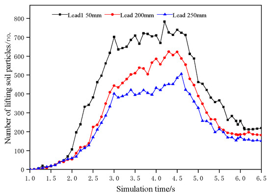
Figure 10.
Variation in the number of soil particles lifted by the hole formers with different leads.

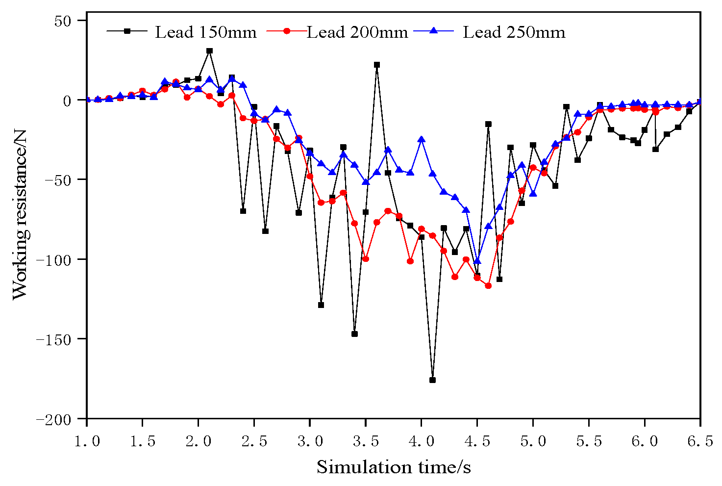
Figure 11.
Variation in the working resistance of the hole formers with different leads.
Figure 10 shows that the number of lifted soil particles decreased with the increase in lead diameter. During the whole hole-forming period, the number of lifted soil particles increased first and then decreased, and the lifting of soil particles largely occurred in the residence periods at the bottom of the hole. Figure 11 shows that with the increase in lead diameter, the fluctuation amplitude of the working resistance decreased. Based on the consideration of operation stability, the lead of the hole former was finally designed to be 250 mm, and the residence periods at the bottom of the hole could be appropriately increased in the actual operation to enhance the lifting capacity of soil particles.
3.2. Analysis of Hole-Forming Mechanism
3.2.1. Theoretical Analysis of Hole-Forming Mechanism
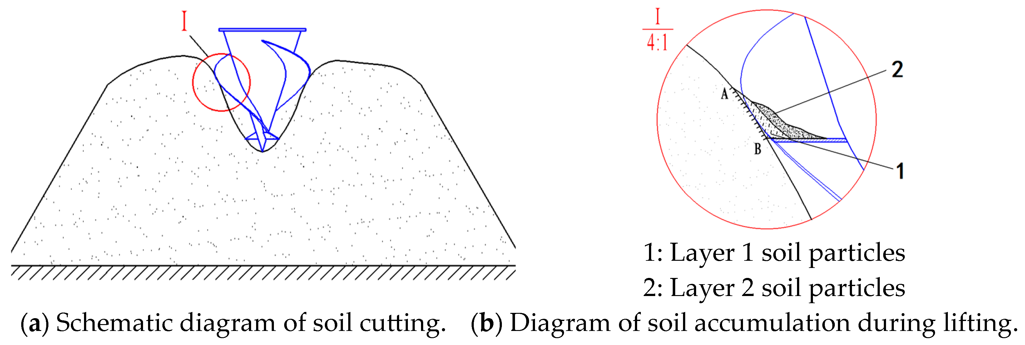
Figure 12 suggests that when the spiral hole former contacted the soil, the lower blade first cut the central soil, and then, the cut soil was squeezed into granular bodies, which were thrown onto the ridge surface around the hole under the action of inertial centrifugal force. With the descending movement of the hole former, the spiral blades also participated in soil cutting, and the hole diameter was continuously expanded, and the soil cutting was completed layer by layer (Figure 12a). When the hole former descended to a certain depth to form a cone-shaped hole, the cut soil particles were driven by the higher rotation speed of the spiral blade to obtain a larger inertial centrifugal force, and under the action of this inertial centrifugal force, the soil particles were pushed around against the friction of the blade and compacted against the hole wall. This resulted in soil accumulation on the hole wall (Figure 12b). Friction was generated between the hole wall and the soil at the contact surface AB, and under the action of this friction, the rotational angular velocity of soil particles lagged behind that of the spiral blade. Driven by the spiral blades, the first layer of soil particles slid along the spiral surface and slid up along the spiral trajectory. The second layer of soil particles was driven by the first layer of soil particles to slide and rise under the action of internal friction. The internal friction between soil particles was predominantly affected by the rotational inertia centrifugal force and the friction coefficient between soil particles, and their relationship is a direct one. The closer to the center of the hole former, the smaller the internal friction between soil particles. When the soil particles were transported to the top of the blade, they were thrown out of the hole under the action of inertial centrifugal force. Therefore, the spiral hole-forming machine made a large hole through the process of cutting soil, lifting soil, and discharging soil. Furthermore, because the soil was an open and complex natural body, it was difficult to avoid the phenomenon of soil returning to the hole in the process of hole formation.
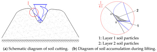
Figure 12.
Schematic diagram of hole-forming process.
3.2.2. DEM Analysis of Hole-Forming Mechanism
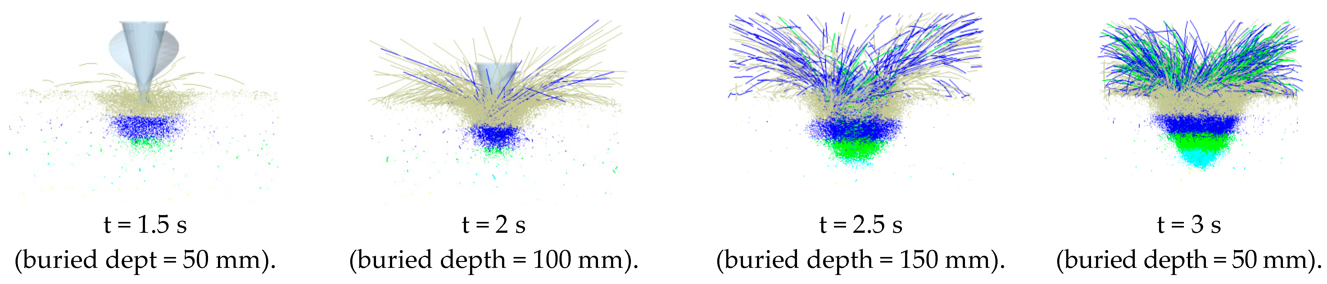
Figure 13 and Figure 14, respectively, show the soil particle disturbance and streamline during the process of hole formation. These figures indicate that when t = 1–1.5 s, the hole former cut the first layer of soil, and some soil particles in the first layer were thrown around the hole; when t = 1.5–2 s, the hole former cut the second layer, and the soil particles thrown out principally came from the first layer; when t = 2–2.5 s, the hole former cut the third layer, and the soil particles thrown out mainly originated from the first and second layers; when t = 2.5–3 s, the hole former cut the fourth layer, and the soil particles thrown out mostly came from the second and third layers, and the soil particles in the fourth layer were rarely thrown out. It was observed that in the first, second, and third layers, holes were primarily formed by discharging soil, and in the fourth layer, holes were chiefly formed by extruding soil. The simulation results demonstrated that the hole former met the design requirements of compound hole formation by extruding soil and discharging soil. Figure 14 shows that the thrown soil particles followed an oblique throwing motion, and with the increase in buried depth, the thrown soil particles increased and the oblique throwing angle increased. To shorten the throwing distance of soil particles, reduce dust, and increase safety, a protective device was added.
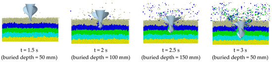
Figure 13.
Simulation of soil disturbance during hole-forming process.
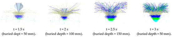
Figure 14.
Streamline diagram of soil particles during hole-forming process.
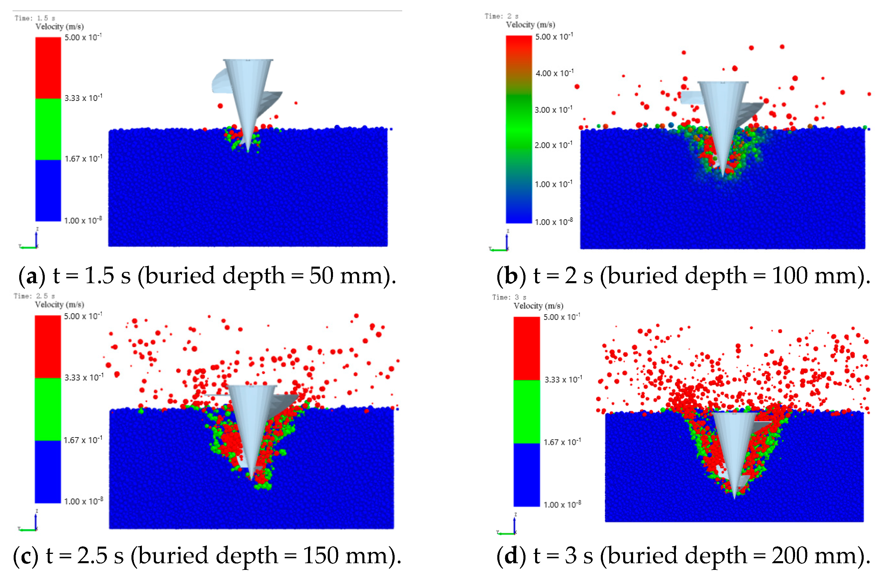
To study the lifting mechanism of soil particles in the hole-forming process, the simulated velocity of soil particles was visualized, and the velocity diagram of soil particles was obtained (Figure 15), in which red color indicates the maximum velocity and blue color indicates the minimum velocity. Figure 15 suggests that the red soil particles near the spiral blade had a higher speed at different buried depths and slid up along the spiral surface. When the soil particles rose toward the hole mouth, they were thrown out of the hole under the action of inertial centrifugal force. There was a layer of green low-speed soil particles near the hole wall, which mainly occurred due to the disturbance caused by the rotation of the spiral blade, which made the soil particles slide down, and this sliding movement of the soil particles finally led to soil returning to the hole during the hole-forming process. A schematic diagram of hole formation (Figure 16) shows that the soil returning predominantly occurred in the topsoil with the greatest disturbance.

Figure 15.
Schematic velocity diagram of soil particles during hole-forming process.
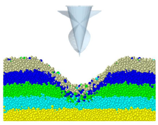
Figure 16.
Schematic diagram of hole formation.
In summary, the simulation study of the hole-forming process was consistent with the theoretical analysis and further revealed the hole-forming mechanism of the spiral hole former for soil cutting, soil lifting, soil discharging, soil extruding, and soil returning.
3.3. Analysis of Field Test Results
The field test results are presented in Table 4. Comparing the test data in Table 4 with the experimental data of the prototype developed by Liu Guanghui, Hu Changshou, etc. [30,31], the hole qualification rate of the original prototype was 85% at its height, and the hole qualification rate of the machine reached 88.5% after the optimization of the simulation parameters. The optimized parameters of the conical twin-screw hole-former helical guide of the machine had lower operating resistance and a lower fluctuation in resistance value, which has the advantages of convenient operation and good working efficiency compared to the original prototype machine. The holes formation met the agronomic requirements, and the bottoms of the holes were tapered, which was conducive to water storage, cooling and moisture conservation, and the prevention of seedling burning. In addition, we found in the field experiment that the main factors affecting the hole-forming process were soil moisture, the rotation speed of the spiral hole former, the residence time at the bottom of the hole, the installation height of the protective cover, and the proficiency of the operator. The soil moisture content had a great influence on the formation of holes. Under the premise of suitable soil moisture and full soil moisture, the soil had certain plasticity and good hole-forming properties. To improve the qualified rate of hole formation under the condition of low soil moisture content, the residence time at the bottom of holes should be appropriately increased.
Table 4.
Field test results of the hole-forming machine.
4. Conclusions
A conical, double-spiral hole-forming machine was innovatively designed for DPLH, which can realize the composite hole-making mode of lower extrusion and upper soil discharge, which ensures that the production of large holes can be completed even under the condition of poor soil moisture.
Based on DEM simulation analysis, the main structural parameters and working parameters of the hole-forming machine were optimized. When the rotation speed was 500–600 rpm and the spiral lead was 250 mm, the hole former worked smoothly, and the residence periods at the bottom of the hole were appropriately increased to enhance the lifting capacity of soil particles.
And DEM simulation revealed the hole-forming mechanism of the spiral hole former as follows: the formation of a large soil hole is a process in which a blade cuts the soil, and the spiral blade transports and discharges the soil. At the same time, a small amount of soil return is inevitable during the hole-forming process, which has little influence on the formation of a large hole, and an appropriate amount of soil returning is beneficial to the later transplantation.
The field test results demonstrated that the prototype was easy to operate, with high working efficiency and good working performance. The qualification rate of the hole was 88.5%, and the efficiency of holes reached 759–812 UPH. In the field experiment, we found that the main factors affecting the hole-forming process were soil moisture, the rotation speed of the hole former, the residence time at the bottom of the hole, the installation height of the protective cover, and the proficiency of the operator.
Author Contributions
Conceptualization, L.Y.; data curation, L.Z. (Le Zheng); formal analysis, X.W., F.Z. and L.Z. (Limei Zhao); investigation, X.W. and F.Z.; methodology, L.Y.; writing—original draft, L.Y. and P.L.; writing—review and editing, P.L. All authors have read and agreed to the published version of the manuscript.
Funding
This research was supported by the Guizhou Provincial Science and Technology Plan Program (QKHZC[2023]327); Scientific Research Project of Introducing Talents in Guizhou University (GDRJHZ[2015]48); Guizhou Province Science and Technology Innovation Base Construction Project (QKHZYD[2023]010); the National Natural Science Foundation of China (Grant No. 52065007).
Institutional Review Board Statement
Not applicable.
Data Availability Statement
The data presented in this study are available on request from the author.
Acknowledgments
All individuals included in this section have consented to the acknowledgement.
Conflicts of Interest
The authors declare no conflicts of interest.
References
- Liu, D.; Gong, Y.; Zhu, Y.; Yao, K.; Chen, X.; Wang, G.; Zhang, X. Design and experiment of key part of 2ZXS-2 cantaloupe transplanter. INMATEH Agric. Eng. 2022, 68, 367–372. [Google Scholar] [CrossRef]
- Liang, B. Study on the Quality Characteristics, Influencing Factors and Upgrading Techniques of Honghe Tobacco Leaves. Ph.D. Thesis, Huazhong Agricultural University, Wuhan, China, 2018. [Google Scholar]
- Liu, G. Analysis and Experiment on the Cavitation of Dry and Wet Soil Environments. Ph.D. Thesis, Guizhou University, Guiyang, China, 2018. [Google Scholar]
- Liu, J.; Yuan, G.; Yang, Y. Development of multifunctional compound soil preparation machine for rotary tillage, ridging and pond. For. Mach. Woodwork. Equip. 2017, 45, 34–36. [Google Scholar]
- Yan, F.; Hu, X.; Li, J.; Li, W.; Lu, Y.; Tang, B.; Long, W.; Zhao, L.; Wang, J.; Wang, Y. Design of small stepping electric pond-beating transplanter. Anhui Agric. Sci. Bull. 2017, 23, 140–142+146. [Google Scholar]
- Xiang, W.; Wu, M.; Lyu, J.; Ma, L.; Quan, W.; Liu, J. Design and testing of transplanting hole-forming machine for potted rapeseed seedlings. In Proceedings of the 2019 11th International Conference on Measuring Technology and Mechatronics Automation, ICMTMA 2019, Qiqihar, China, 28–29 April 2019; pp. 49–56. [Google Scholar]
- Xiang, W.; Wu, M.; Guan, C.; He, Y. Design and test of transplanting hole-forming machine for rapeseed potted seedlings. Trans. Chin. Soc. Agric. Mach. 2017, 48, 40–48. [Google Scholar]
- Jiang, K. Study on the theory of soil-lifting by the drill bit of the digger—Discussion on the critical speed of the drill bit. J. Cent. South Univ. For. Technol. 1997, 3, 71–75. [Google Scholar]
- Quan, W.; Wu, M.; Guan, C.; Luo, H. Experimental study on the shape optimization of the hole-forming device of rape pot seedling transplanter. J. Agric. Sci. Technol. 2021, 23, 97–106. [Google Scholar]
- Xiang, W.; Wu, M.; Lu, J.; Ma, L.; Quan, W.; Liu, J.; Xiao, L. Simulation and experimental study on the working performance of rape transplanting hole-forming device based on DEM. J. Agric. Sci. Technol. 2019, 21, 70–81. [Google Scholar]
- Quan, W.; Wu, M.; Luo, H.; Chen, C.; Xie, W. Hole-forming operation mode and parameter optimization of rape pot seedling transplanter. Trans. Chin. Soc. Agric. Eng. 2020, 36, 13–21+327. [Google Scholar]
- Han, C.; Xu, Y.; You, J.; Zhang, J.; Yuan, P. Parameter optimization of the hole-forming machine of semi-automatic compressed matrix watermelon pot seedling transplanter. Trans. Chin. Soc. Agric. Eng. 2019, 35, 48–56. [Google Scholar]
- Huang, X.; Yuan, M.; Mao, H.; Chao, J. Study on transplanting techniques of flue-cured tobacco seedlings under plastic film in Xiangxi tobacco-growing areas. Mod. Agric. Sci. Technol. 2017, 15, 9+13. [Google Scholar]
- Wang, D.; Sun, Y.; Du, Y.; Liu, Y.; Wang, Y.; Ma, X.; Zhang, Y.; Zhang, R. Effects of transplanting time and methods on the growth, yield and quality of flue-cured tobacco. Crops 2021, 2, 87–95. [Google Scholar]
- Feng, C.; Wang, X.; Zhang, J.; Dong, J.; Yu, X.; Wang, Y.; Ling, A. Study on the optimum light transmittance of plastic film for transplanting seedlings under plastic film. Chin. Tob. Sci. 2020, 41, 16–21. [Google Scholar]
- Yu, L.; Hu, C.; Xu, Z.; Zhang, F.; Fu, D. Design and experiment of spiral hole-forming device for big nest transplantation. J. Agric. Mech. Res. 2020, 42, 198–202. [Google Scholar]
- Liu, G.; Yu, L.; Chen, X.; Wu, X. Design and experiment of backpack deep-planting hole-forming machine. Jiangsu Agric. Sci. 2018, 46, 263–267. [Google Scholar]
- Kumawat, L. Development of draft force estimation model for hand tractor powered digger-cum-conveyor by rake angle and digging depth. J. Biosyst. Eng. 2023, 48, 152–164. [Google Scholar] [CrossRef]
- Zhao, Z. Finite Element Analysis of Drill Bit and Motion Simulation of Suspension Mechanism of Digger. Ph.D. Thesis, Northwest A&F University, Xianyang, China, 2010. [Google Scholar]
- Qu, J. Finite Element Analysis of the Main Shaft of the Digging Machine and Dynamic Simulation of the Suspension Mechanism. Ph.D. Thesis, Northeast Forestry University, Harbin, China, 2006. [Google Scholar]
- CAAMS. Agricultural Machinery Design Manual; China Agricultural Science and Technology Press: Beijing, China, 2007. [Google Scholar]
- Geng, D. New Agricultural Mechanics; National Defense Industry Press: Beijing, China, 2011. [Google Scholar]
- Ji, Y.; Yu, M.; Li, C. Discrete element simulation of shovel pore-forming machine. J. Jiangsu Univ. (Nat. Sci. Ed.) 2014, 35, 40–43. [Google Scholar]
- Li, B.; Chen, Y.; Chen, J. Modeling of soil-claw interaction using the discrete element method (DEM). Soil Tillage Res. 2016, 158, 177–185. [Google Scholar] [CrossRef]
- Huang, Y.; Hang, C.; Yuan, M.; Wang, B.; Zhu, X. Discrete element simulation and experiment of subsoiling soil disturbance behavior. Trans. Chin. Soc. Agric. Mach. 2016, 47, 80–88. [Google Scholar]
- Ucgul, M.; Fielke, J.M.; Saunders, C. Three-dimensional discrete element modeling of tillage: Determination of a suitable contact model and parameters for a cohesionless soil. Biosyst. Eng. 2014, 121, 105–117. [Google Scholar] [CrossRef]
- Fang, H.; Ji, C.; Farman, A.C.; Guo, J.; Zhang, Q.Y.; Chaudhry, A. Analysis of soil movement behavior in rotary tillage process based on discrete element method. Trans. Chin. Soc. Agric. Mach. 2016, 47, 22–28. [Google Scholar]
- Wang, X.; Yue, B.; Gao, X.; Zheng, Z.; Zhu, R.; Huang, Y. Simulation and test of soil disturbance behavior of subsoiling shovel with different wing shovel installation heights. Trans. Chin. Soc. Agric. Mach. 2018, 49, 124–136. [Google Scholar]
- Feng, C. Study on Viscosity Reduction and Desorption of Pepper Duckbill Planter Based on Yellow Clay. Ph.D. Thesis, Guizhou University, Guiyang, China, 2022. [Google Scholar]
- Yu, L.; Liu, G.; Zhang, F.; Wu, X.; Hu, C. Test and Analysis for Performance on the Knapsack Well-cellar Making Machine for Seedling Transplanting. J. Agric. Mech. Res. 2018, 40, 141–145. [Google Scholar]
- Hu, C.; Yu, L.; Xu, Z.; Zhang, F.; Chen, Y. Improvement and Experiment Main Component of Well-cellar Making Machine for Tobacco Seedling Transplanting. J. Agric. Mech. Res. 2019, 41, 198–202. [Google Scholar]


Disclaimer/Publisher’s Note: The statements, opinions and data contained in all publications are solely those of the individual author(s) and contributor(s) and not of MDPI and/or the editor(s). MDPI and/or the editor(s) disclaim responsibility for any injury to people or property resulting from any ideas, methods, instructions or products referred to in the content. |
© 2024 by the authors. Licensee MDPI, Basel, Switzerland. This article is an open access article distributed under the terms and conditions of the Creative Commons Attribution (CC BY) license (https://creativecommons.org/licenses/by/4.0/).