Abstract
To regulate the energy flow in orchard ecosystems and maintain the environment, weeding has become a necessary measure for fruit farmers, and the use of automated mowers can help reduce labor costs and improve the economic efficiency of orchards. However, due to the complexity of the geographic and spatial environment of the orchard, in particular, the loose and undulating road surface, the interference of satellite signals by large trees, etc., which decreases the positioning accuracy and stability of the positioning system of the mower, and the high cost of the sensor also affect the popularization of intelligent mowers for these applications. To address the above problems, this paper constructs a positioning system through a low-cost global navigation satellite system (GNSS), inertial measurement unit (IMU), and odometry, and utilizes the Kalman filter algorithm based on the error state for a combined GNSS/IMU positioning so that the inertial navigation system can maintain a more accurate positioning when the GNSS signals are poor. Considering the side-slip and error accumulation problems of the odometry of the traction mower, the combined GNSS/IMU positioning information is used to optimize the odometry model and improve the navigation and positioning accuracy. To reduce the measurement error of the IMU and the problem of error accumulation, this paper utilizes the nonholonomic constraint (NHC) of a lawn mower to suppress the dispersion of IMU measurement errors and constructs periodic and nonperiodic zero-velocity updating (ZUPT) strategies in combination with the travel paths of lawn mower navigation operations in the region to update the IMU data to improve the positioning accuracy and stability of the positioning system. The experiments show that the average error of the constructed positioning system is controlled within 0.15 m, the maximum error is maintained at approximately 0.3 m, and the positioning system constructed by using low-cost sensors can achieve a positioning accuracy similar to that of the differential global navigation satellite system (DGNSS), which is beneficial for the promotion and application of intelligent mowers in orchards.
1. Introduction
The presence of weeds in an orchard environment can have adverse effects on the yield and quality of the fruit. In addition to competing with fruit trees for nutrients and living space, weeds can also increase the difficulty of the daily management and cultivation of the orchard harvest, thereby reducing the economic benefits of the orchard production process. Therefore, to regulate the energy flow of the orchard ecosystem and maintain the environment, weeding has become a necessary measure for fruit farmers. The traditional method of manual weeding is a slow, repetitive, and laborious process that involves high labor costs. The process of weeding also causes noise and exhaust pollution, which affects the health of workers. With the continuous development of the social economy, the gradual progress of agricultural modernization to improve the efficiency of agricultural production and reduce labor costs by improving the intelligence of orchard mowers to reduce unnecessary labor has reached a consensus. The intelligent mower is capable of performing all-weather, high-efficiency mowing operations in the orchard, which has the effect of reducing labor costs, improving orchard management and production efficiency, and overcoming the disadvantages associated with traditional human and mechanical mowing [1,2]. The positioning system is an extremely critical part of the process of the autonomous mobile weeding operation for intelligent lawn mowers. When a lawn mower moves according to a planned path, its position information will constantly change, and a positioning system is needed to ensure the positioning accuracy of the lawn mower and to provide accurate positioning information for the safe and stable operation of navigation operations to realize the requirements of the autonomous navigation operation of lawn mowers with full coverage of the orchard environment area. An accurate navigation and positioning system can facilitate a number of benefits for autonomous lawn mowers. It can effectively provide information about the position of the mower and the surrounding environment, enabling the mower to make corresponding correct decisions and ensuring the safety of the autonomous movement process. Furthermore, it can optimize the autonomous driving route and improve the efficiency of the mower’s autonomous mowing operation. Consequently, the investigation of high-precision positioning systems is of paramount importance for the advancement of intelligent lawn mowers.
In the outdoor environment, although the DGNSS can provide more accurate positioning information in most cases, considering the difficulty of promoting the application of orchard smart mowers, the cost of the sensor and its subsequent use is a problem that cannot be ignored, considering the difficulty of promoting the application of smart mowers in orchards. The high cost of GNSS differential services increases the cost of lawn mower navigation operations; therefore, when an existing positioning system can achieve high-precision positioning, it should attempt to turn off the differential service to reduce the cost, and a single GNSS module positioning frequency that is low in orchard environments is also susceptible to signal obstruction, unstable communication delays, ground reference station distance limitations, and other issues affecting the accuracy of GNSS positioning; therefore, it often needs to be combined with other sensors for positioning [3,4,5,6]. Mower chassis motors are generally equipped with encoders, so the mower positioning accuracy is often improved by constructing a mower odometry algorithm. The odometry algorithm is synthesized from encoder information, kinematic models, and track derivation algorithms that calculate the rotation of tracks and then convert it into positioning information through the rotation of motors monitored by encoders; however, problems such as measurement errors, mower modeling errors, and error accumulation make odometry positioning errors significant; in particular, the complexity of the orchard pavement environment makes the accuracy of odometry positioning face many difficulties [7,8,9,10,11]. Compared to sensors such as lidar and cameras, the IMU is much less expensive. It does not rely on any external information, has a very high measurement frequency, can be used in a variety of complex environments, and can be effectively used to improve the positioning accuracy of the GNSS and odometry positioning. The only disadvantages are the problems of measurement error and error accumulation. For this reason, a large number of researchers have proposed solutions to the problem of IMU errors and combined various methods to improve the performance of the positioning system and reduce the error [12,13,14,15,16,17]. Hongliang, Y et al. constructed a combined EKF-based navigation algorithm using the BDS/INS system and proposed a zero-speed correction and heading constraint method to reduce the positioning system error. This improved the position, velocity, and level accuracy of the original positioning system to different levels [18]. The principle is to utilize the characteristics of the platform on which the IMU is mounted or its working environment to carry out the direct information-assisted updating of IMU data. Takanose et al. proposed a GNSS/IMU positioning system that uses odometry to construct a speed estimation function with an optimized timing data method to reduce the positioning system error, which effectively improved the positioning accuracy compared to the Kalman filtering method [19]. This means that the IMU data are updated by mutual feedback from the IMU and the odometry model. In addition, Alkhawaja et al. proposed the integration of a depth camera with an IMU for the positioning system of mobile robots. The error of the IMU is reduced by a deep inertial data method based on a feed-forward cascade correlation network. The average mean square error of the method is 0.091 m, which represents a 56% reduction in error compared to the error of the artificial neural network [20]. However, this method adds extra sensors, which undoubtedly increases the cost and complexity of the positioning system, so the indirect information that helps to update the IMU should be used to its fullest extent in selecting the existing sensors.
With the above analysis, to build a high-precision positioning system, the combination of direct information, indirect information, and model information assistance can be considered to reduce the error of the IMU, and then the IMU can be used to reduce the positioning error of the GNSS and odometry. Therefore, in this paper, an orchard mower built in the laboratory is used as an experimental platform. First, to prevent the GNSS signal from degrading the positioning accuracy due to interference, a combined GNSS/IMU positioning system based on error-state Kalman filtering is designed to ensure the positioning accuracy of the IMU when it operates independently, and, to reduce the error of the odometry and the error due to the characteristics of the sensors through the complementary filtering algorithm, an optimized original crawler-type odometry model with the combined positioning information of the GNSS/IMU is proposed. To reduce the IMU error problem, NHC, and periodic and nonperiodic ZUPT methods are utilized to continuously update the IMU data. The established positioning system can improve the positioning accuracy of mowers with limited sensor costs and accelerate the agricultural promotion and application of smart mowers in orchards.
2. Materials and Methods
2.1. Test Materials
The positioning accuracy of the constructed positioning system is tested using the traction intelligent mower developed by the National Lychee and Longan Industrial Technology System Team of South China Agricultural University as an experimental platform. The whole mower is shown in Figure 1, which is divided into two parts, the crawler chassis and the mowing device, both of which are connected by means of traction towing.
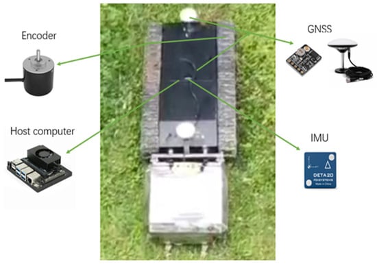
Figure 1.
Mower and sensors.
The IMU, GNSS, and odometry are mainly used to build the positioning system. The IMU module is DETA20, which is mounted and fixed at the center of the mower body, and its main parameters are shown in Table 1. The GNSS module is ATGM336H-5N, and the GNSS dual antennae are mounted at the front and rear of the mower chassis and are symmetrical about the center of the body; the main parameters are shown in Table 2. This mower odometry positioning method uses a 2500-line incremental encoder built into the chassis motor, and the host computer communicates with the motor driver through the USB serial port to indirectly obtain motor encoder information on both sides. The GNSS and IMU modules communicate directly with the main control board through the USB serial port, and all three use the system network time as the time stamp to synchronize and align the time data of each sensor.

Table 1.
Main parameters of the GNSS module.
Table 2.
Main parameters of the IMU module.
2.2. Experimental Methods
2.2.1. Definition of the Co-Ordinate System
The positioning system contains multiple sensors which need a defined co-ordinate system, in which the IMU module outputs motion information based on inertial co-ordinate system i. The GNSS module outputs positioning information based on earth co-ordinate system e, as shown in Figure 2. The odometry outputs the positioning information in terms of the b-system of the mower’s base co-ordinate system. In addition, the mower in the whole navigation and positioning process for navigation co-ordinate system n is used as a reference to represent its global positioning information. This paper uses the navigation and positioning starting position of the mower center of mass as the origin and the mower matrix co-ordinate system of the X, Y, and Z direction to establish the navigation co-ordinate system, as shown in Figure 3. The relative relationship between the mower base co-ordinate system and the navigation co-ordinate system indicates the change in the mower’s motion. The construction of a mower positioning system can be realized by transforming between co-ordinate systems [21].
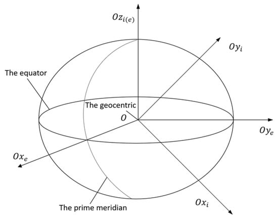
Figure 2.
Earth co-ordinate system and the inertial co-ordinate system.
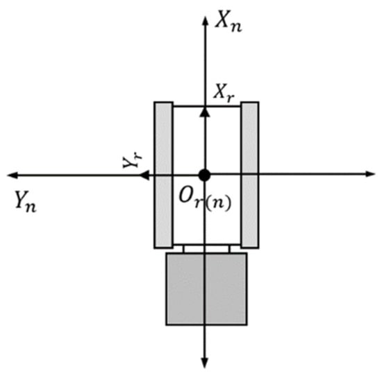
Figure 3.
Mower and navigation co-ordinate systems.
2.2.2. Experimental Methods and Procedures
To verify the efficiency of the proposed method in the next section, the tractor mower experimental platform is used to test the positioning accuracy in a relatively open orchard environment. By controlling the movement of the mower in the environment, the positioning system calls each sensor data point in real time to obtain the positioning results. Given the numerous obstacles present in the orchard environment, we elected to conduct our experiments in a more open area, measuring approximately 8 m in length and 3 m in width. After advanced testing, it was determined that the differential GNSS signal in this area is of high quality, and the positioning accuracy can reach the centimeter level with high positioning accuracy. Therefore, the whole experiment uses the differential GNSS positioning result as the reference value, and the experimental site is shown in Figure 4.
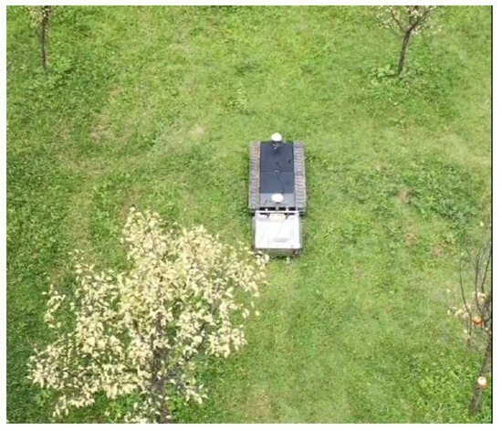
Figure 4.
Experimental scene.
The positioning system constructed in this paper contains many kinds of positioning algorithms. To facilitate the observation of the positioning results of each positioning algorithm, two experiments are carried out. Experiment 1 is a positioning error comparison experiment without IMU data updating methods, which is used to verify the difference in the positioning accuracy of each positioning algorithm. Experiment 2 is the positioning accuracy experiment where the IMU data are updated, which is used to verify the difference in positioning accuracy after introducing the IMU data update to the original positioning algorithm. Due to the inclusion of the ZUPT in Experiment 2 and to reduce the influence of other factors on the experiments, each positioning of the data from the saved records of Experiment 1 is carried out in the form of a dataset for Experiment 2, while a few timestamps are marked as path target points. To simulate the presence of satellite signal occlusion, random GNSS noise errors are then added to the dataset [22,23].
2.3. Orchard Mower Positioning System Design
2.3.1. IMU/GNSS Combined Positioning Design
The IMU module mainly outputs acceleration, angular velocity, and quaternion information, and the quaternion q can be described as:
where is the real part, , , and are the virtual parts, and , , and are pure complex numbers whose sum of squares is −1.
The attitude information can be effectively obtained from its quaternion, while position velocity information can be realized by integrating the acceleration and angular velocity, and we set the measurement model as:
where represents the transformation matrix from the inertial co-ordinate system of the IMU to the base co-ordinate system at moment t; and are the angular velocity and acceleration information on an axis measured by the IMU, respectively; and represent their bias noise; and represent their measured white noise; and and represent the true angular velocity and acceleration information at that moment in time. The acceleration of gravity is represented by g.
obeys a Gaussian distribution satisfying , , and the variation of the bias noise can be viewed as Brownian motion, which, after differentiation, agrees with the nature of white noise, satisfying , . Therefore,
Assume that, in a very short time ∆t, , , and remain unchanged. Integration of the data measured by the IMU for a particular axis at that time can be obtained:
where represents the initial velocity at moment t, and represents the initial displacement at that moment.
Therefore, the relationship between the position increment on an axis of the IMU before and after the state transformation is the IMU pre-integration, which can be expressed as:
where subscript represents the state quantity before the state transformation, and subscript represents the state quantity after the transformation.
The IMU pre-integration and subsequent co-ordinate transformation can be used to obtain its speed, position, and attitude information in the navigation co-ordinate system. The GNSS module moves through the receiver from the satellite to obtain information, and, then, using the standard satellite navigation equipment protocol, NMEA format data interpretation can be obtained from its longitude, latitude, and altitude. Figure 2 shows the Earth co-ordinate system , that is, the east, north, and sky directions of the speed of information , , . Using the calculation of different moments of the acquired information to obtain the location of the position of the attitude changes, the conversion of the co-ordinate system can be obtained in the navigation co-ordinate system under the speed of the GNSS and the position of the attitude of the information [24].
To realize the combined GNSS and IMU positioning, the IMU module measurement information, as its system state quantity, can be set as:
The system state space equation is defined as:
where is the state prediction matrix, is the noise assignment matrix, and is the IMU system noise containing the three-axis acceleration and angular velocity sensor bias noise and measurement white noise, as determined by the IMU module accuracy parameters.
Using Equation (2), the IMU system noise can be calculated as follows:
Then, the measurement information acquired by the GNSS module through resolution is set as its system state quantity, which can be set as:
Because of the large order of magnitude difference between the measurement information of the GNSS and IMU modules, direct data fusion processing of the two will increase the dispersion of the error; therefore, the error estimation of the position, velocity, and attitude information under the navigation co-ordinate system obtained by the co-ordinate conversion of the IMU and GNSS modules is considered the observation quantity, the Kalman filter is constructed based on the error state, and the observation state quantity can be set as:
where , , , , , and represent the position, velocity, and attitude information of the IMU pre-integration and GNSS positioning system in the navigation co-ordinate system, respectively.
Therefore, the systematic observation equation is established as:
where is the measured white noise error matrix of the GNSS, which can be set by the accuracy parameter of the GNSS equipment, while and are the observation conversion matrices of the IMU and GNSS, respectively.
The above equation combined with the Kalman filter gain and data update equation can be established based on the error state of the Kalman filter model. This method allows the use of an IMU alone to maintain a certain level of accuracy when the GNSS signal is affected. The combination of positioning principles is shown in Figure 5.
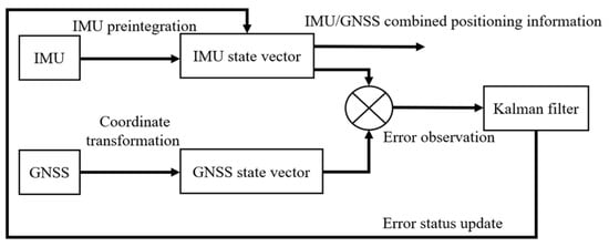
Figure 5.
IMU/GNSS combined positioning system.
2.3.2. Optimization of the Odometry Model for Tractor Mowers
The tractor mower in this paper is mainly controlled by differential speed through the tracked active wheels on both sides of the chassis, so the ideal kinematic model can be constructed based on the following assumptions [25]:
- (1)
- The center of mass of the mower coincides with the center of geometric velocity, and no side-slip with the ground occurs during motion;
- (2)
- Since there is only one drive motor on each side, the kinematic model is simplified to a two-wheel differential model;
- (3)
- The deformation of the track, the change in the contact surface between the track and the ground, and the effect of transmission resistance are neglected.
We establish a world co-ordinate system in the plane, and then establish a mower motion co-ordinate system with the mower center of mass as the origin, the forward positive direction of the mower as , and the -axis perpendicular to the left side of the forward positive direction. is the -axis co-ordinate in the world co-ordinate system, is the -axis co-ordinate, and is the angle between the positive direction of the mower co-ordinate system and the positive direction of the axis of the world co-ordinate system, which is the yaw angle. The speed of the left track of the mower is represented by , the right track speed is , the center-of-mass linear velocity is , the angular velocity is , the length of the two sides of the center of the track is represented by L, the radius of the steering is R, and the yaw angle is , as shown in Figure 6.

Figure 6.
Model of the ideal odometry.
The geometric relationship can be obtained from Figure 6, and can be expressed as:
The variation of can be expressed as:
where is the state change time.
Then, can be expressed as:
Thus, can be expressed as:
The positional attitude of the mower in the world co-ordinate system is defined as (, , ), and the linear velocity of the mower can be expressed as:
Integrating Equation (16) yields the ideal state mower odometry model:
With the above odometry model, the left and right track speeds obtained from the motor encoders on both sides can be converted into odometry positioning information in the world co-ordinate system, and then converted to obtain odometry positioning information in the navigation co-ordinate system.
Since the center of mass of the mower and its geometric velocity center are not exactly coincident, the relative displacement of the track and the ground will occur when the angular velocity is not 0 during the steering process, and, because of the change in the terrain, the movement of the mower, the deformation of the track, and the accumulation of the error, etc., there will be a different deviation between the ideal model odometry and the actual situation; therefore, it is necessary to optimize the odometry model of the mower.
When driving straight, the ideal odometry is mainly affected by the measurement error and the error accumulation, considering the lag of the data acquired by the encoder, the reliability of a single sensor, and the characteristic problems of each sensor. This paper uses the complementary filter algorithm to estimate the actual mower-line-speed-optimized odometry model by fusing the line speed derived from the combined positioning of the motor encoder and the IMU/GNSS:
where is the estimated value of the complementary filter. and are the linear velocities measured by the encoder and the linear velocities derived from the IMU/GNSS combination, respectively. The transfer function is a first-order high-pass filter, and is a first-order low-pass filter. The transfer function of the filter is as follows:
This means that a high-pass filter is applied to , retaining the high-frequency portion, which is mainly used to capture transient information changes, and a low-pass filter is applied to , retaining the low-frequency portion, which is used to provide stable information over a long period of time. The fused speed information is substituted for the speed information derived from the encoder for the original odometry model. Therefore, the mower odometry model is optimized for straight driving:
where is the linear velocity obtained after complementary filtering.
While turning, in addition to the error in straight driving, the outer high-speed track of the mower will slip backward due to being pulled by the inner low-speed track, while the inner low-speed track will slip forward due to being pulled by the outer high-speed track, which means that side-slip occurs, making the odometry model as shown in Figure 7.
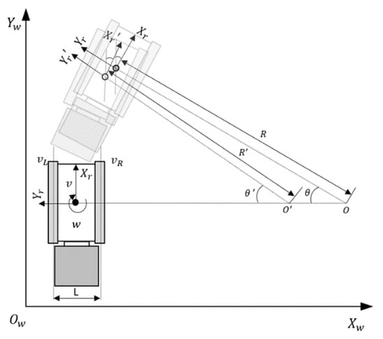
Figure 7.
Model of the mower odometry during side-slip.
The uneven forces and the different contact conditions between the ground and the track can make the side-slip different, making the angular velocity and steering radius measured by the motor encoder inaccurate. Therefore, in this paper, the angular velocity and steering radius derived from the combined IMU/GNSS positioning are used to replace the data measured by the motor encoder in the ideal odometry model. Therefore, when steering, the mower odometry model is optimized as:
where and are derived from the combined GNSS/IMU positioning information.
2.3.3. Design of the ZUPT-Based Mower Positioning System
It can be seen from the previous section that the accuracy of the IMU data has a great impact on the whole positioning system, so it is crucial to ensure the accuracy of the IMU data. The error-state matrix for the IMU pre-integration in the navigation co-ordinate system can be created as:
where , , and represent the attitude, velocity, and position errors of the IMU pre-integration in the navigation co-ordinate system, respectively. and are from Equation (2).
Since the controllable degrees of freedom of the mower are less than its total degrees of freedom, the NHC can be utilized to limit the data output from the IMU when its lateral sliding and motions perpendicular to the ground are not considered. This means that the data output from the IMU have zero velocity in the direction perpendicular to the movement of the mower and zero velocity in the direction perpendicular to the ground; the principle is shown in Figure 8 [26].
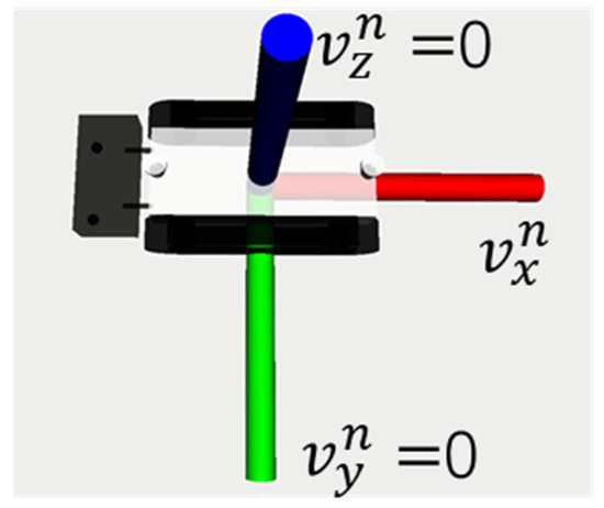
Figure 8.
The principle of the NHC.
Then, the calculated velocity for the measured IMU can be updated with a measurement, and it can be expressed as:
where is the velocity vector calculated by the IMU pre-integration in the navigation co-ordinate system, and .
Although NHC is updated every time IMU pre-integration is performed, speed constraints will fail due to abnormal operation of the mower. This will affect the positioning accuracy and stability of the positioning system, thus it will be necessary to adjust the NHC according to the actual situation.
Under static conditions, the IMU module is mainly affected by measurement errors, except for the Earth’s rotation, so the use of the ZUPT reduces and calibrates the bias of the IMU sensors and maintains the accuracy of the inertial navigation system. Therefore, the measurement matrix can be expressed as:
where , represent the estimated bias noise of the acceleration and angular velocity information, respectively.
Although ZUPT does not provide any positioning information, it reduces the triple error growth of the inertial navigation system positioning to linear growth because its modeling of the error state accounts for the correlation between the velocity and position errors. Therefore, the ZUPT not only limits the error growth but also reduces the cumulative error of the IMU [27]. Since the odometry and IMU are integrated to obtain the positioning information, the error accumulation will be large, while running ZUPT can reduce the accumulated error and rely on the GNSS positioning information to correct the positioning deviation. ZUPT operation is generally accompanied by zero-speed detection, but if the detection is incorrect, the positioning accuracy of the positioning system will be affected. To ensure the precision of zero-speed detection, this paper makes the mower stop actively to ensure that the mower is in a zero-speed state when running the ZUPT.
During the autonomous mowing operation, the GNSS system of the lawnmower has significantly lower dynamic positioning accuracy compared to static positioning accuracy due to factors such as lower receiving frequency and various errors. Therefore, the lawnmower GNSS system is more effective in improving the positioning accuracy of the positioning system only under stationary conditions. While the odometry-optimized positioning is relatively stable due to the mower’s own encoder measurement error and less error accumulation fluctuation, its positioning accuracy is mainly affected by the combined IMU/GNSS positioning information. When the discrepancy between the optimized positioning of the odometry and the IMU/GNSS positioning is considerable, it is usually attributable to the significant measurement error and error accumulation problem of the IMU. Stopping the mower temporarily at this moment and running ZUPT makes the discrepancy between the optimized positioning of the odometry and the IMU/GNSS positioning decrease to within the set residual threshold. It is mainly triggered by using the residual threshold detection method, which calculates the residual between the model-predicted value and the actual observed value, takes the odometry-optimized positioning data as the model-predicted value, and uses the combined GNSS/IMU positioning data as the data-observed value. A detection function is constructed by using the filtered residual information, and the detection function is defined as:
where is the filter residual, and is the covariance matrix of the filter residual.
When the system obeys , it means that the detection is normal; otherwise, it shows a large variance. Therefore, a binary assumption is made on :
where is the null hypothesis, indicating normal detection, and is the alternative hypothesis, indicating large variance in residuals.
Therefore, the detection judgment can be set as:
where is the detection threshold, determined by the preset alarm rate .
The normal operation of the mower can be affected by running the nonperiodic ZUPT for a long time because the threshold value is too small. To prevent this, the error threshold is set to be extremely large at the initial time and subsequently adjusted according to the data information of the positioning system and the demand. As this ZUPT is executed at irregular intervals, it is the nonperiodic ZUPT, which can correct positioning deviations outside the threshold value in time and improve the positioning accuracy of the positioning system.
To simulate the full-coverage automatic mowing operation in the orchard area, the intelligent mower is usually set up with multiple target points to achieve the full-coverage automatic mowing operation in the area, as shown in Figure 9, for the mower to carry out the regional automatic operation of the optimal path schematic diagram, where the serial numbers indicate the target points that the mower must reach in sequence.
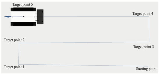
Figure 9.
Schematic diagram of the navigation operation path.
Therefore, combined with the navigation operation path of the mower in the area, the lawn mower will temporarily stop and run ZUPT when reaching the target point. This means that periodic ZUPT reduces the positioning deviation to within the threshold and improves the positioning accuracy. A schematic diagram of the ZUPT-based lawn mower positioning system is shown in Figure 10.
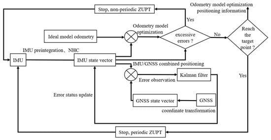
Figure 10.
Schematic diagram of the ZUPT-based positioning system.
3. Results
3.1. Experiment 1: Positioning Error Comparison Experiment without IMU Data Updating Methods
To conveniently analyze the results, the GNSS positioning, IMU pre-integrated positioning, and IMU/GNSS combined positioning are set as comparison Group I. The ideal odometry positioning, IMU/GNSS combined positioning, and odometry optimized positioning are set as comparison Group II. The whole experiment uses the differential GNSS signal in a relatively open environment as the actual reference positioning position. The positioning result graph and the error graph in each direction are shown in Figure 11, and the average error, maximum error, and standard deviation of each positioning algorithm in the X and Y directions of the navigation co-ordinate system are given in Table 3.
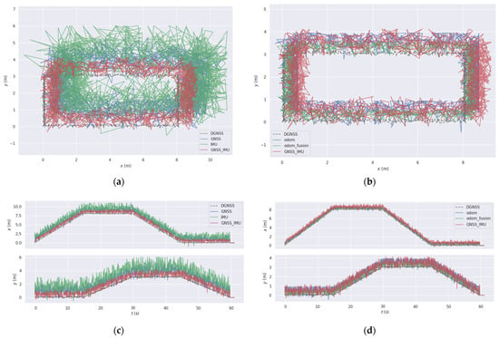
Figure 11.
Comparison of the positioning errors of each positioning algorithm: (a) positioning results for comparison Group I; (b) positioning results for comparison Group II; (c) positioning errors in comparison Group I; and (d) positioning errors in comparison Group II.
Table 3.
X- and Y-direction positioning error table.
The results indicate that the IMU pre-integrated positioning algorithm has the largest average and maximum errors, resulting in the worst positioning accuracy. However, the IMU/GNSS combined positioning provides a large improvement in positioning accuracy for the GNSS or IMU pre-integration alone. The average error of the ideal odometry positioning in the X direction is smaller than that of the combined GNSS/IMU positioning, which may indicate that the original odometry is more reliable in the straightforward positioning but may increase the error in the Y direction after many turns. In contrast, the average error of the optimized positioning of the odometry is stable within 0.4 m. The maximum error is controlled at approximately 0.5 m, which shows that the optimized odometry positioning improves average positioning accuracy by approximately 40% compared to the original odometry.
3.2. Experiment 2: Positioning Accuracy Experiment with the IMU Data Update
To conveniently analyze the results, Method 1 was used for odometry-optimized positioning, Method 2 was used for ZUPT/odometry-optimized positioning, and Method 3 was used for ZUPT/NHC/odometry-optimized positioning. The DGNSS positioning is still used as the actual reference positioning position. The positioning trajectories and errors of each method without adding random noise and with adding noise are shown in Figure 12 and Figure 13, respectively.
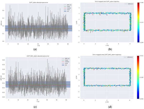
Figure 12.
Diagram of the positioning trajectory and error without random noise: (a) Method 2 positioning error conditions; (b) Method 2 positioning trajectory accuracy; (c) Method 3 positioning error conditions; and (d) Method 3 positioning trajectory accuracy.
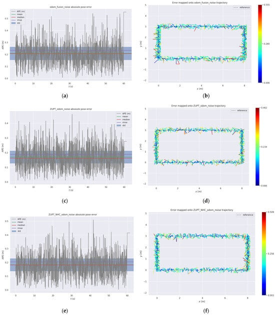
Figure 13.
Diagram of the positioning trajectory and error with random noise: (a) Method 1 positioning error conditions; (b) Method 1 positioning trajectory accuracy; (c) Method 2 positioning error conditions; (d) Method 2 positioning error conditions; (e) Method 3 positioning error conditions; and (f) Method 3 positioning trajectory accuracy.
The results indicate that Method 1 has the largest average error and maximum error, while Methods 2 and 3 have higher positioning accuracies than Method 1, which indicates that the introduction of the ZUPT and NHC in the process of the navigation and positioning of the mower can truly improve the positioning accuracy. When the satellite signal conditions are optimal, the average error of Method 3 is within 0.15 m, with a maximum error of approximately 0.3 m. The addition of IMU data updates significantly enhances the positioning accuracy.
After adding random GNSS noise, all three methods have some resistance to random noise, but it is possible that the change in the velocity information of the mower in the lateral and vertical directions may have caused the NHC method to fail, resulting in a significant decline in the positioning accuracy of Method 3 after the addition of random noise. Therefore, when using the NHC to constrain and limit IMU data, the data need to be adjusted according to the actual situation, and the positioning accuracy may also decrease if the NHC is not used properly.
4. Discussion
The positioning system represents a key component of the orchard smart mower, as accurate and stable positioning information is of vital importance for the autonomous mowing operation to be successfully implemented. In this paper, a positioning system is constructed using an IMU, GNSS, and encoder module, which are combined with the NHC and ZUPT methods to enhance the navigation and positioning accuracy. The proposed method is capable of maintaining a high accuracy in navigation and positioning even when the GNSS signal is temporarily unavailable. Compared to the reference [18], which is limited to static positioning, this method enables the highly accurate positioning of dynamic processes. In addition, the method proposed in this paper is straightforward and achieves a similar positioning accuracy without requiring complex neural network training as in reference [20]. The ESKF-RTS algorithm discussed in reference [28] exhibits a root-mean-square positioning error of approximately 1 m, while the method in this paper is within 0.3 m. Therefore, the method proposed in this paper offers a superior positioning accuracy and reliability.
5. Conclusions
For the autonomous mobile mower to complete the task of full-coverage mowing in a given area, it is essential that the mower accurately arrive at the set target points from its initial position in a successive manner. The precise positioning of the mower during its movement is a prerequisite for the mower to complete the entire task. In this paper, to address the problem of navigation and positioning accuracy in the process of the autonomous mowing operation of orchard mowers, a combined positioning method based on the ZUPT is proposed, which mainly uses a Kalman filter based on the error state to improve the limitations of single-sensor positioning by combining the GNSS and IMU and optimizes the odometry through the combined positioning information of the IMU/GNSS, and the NHC and ZUPT methods are utilized to promptly update the data of the inertial navigation system, thereby ensuring the accuracy of the positioning data. The proposed methods enhance the accuracy of the original positioning techniques to varying degrees and can achieve a similar precision as the DGNSS. In instances where the satellite signal is briefly blocked, our proposed technique is still capable of executing high-precision navigation and positioning with excellent stability. As a result, it can adequately meet the requirements for an autonomous mobile mowing operation in complex orchard environments. Additionally, this study takes into account the practicality and economic feasibility of sensor selection, which reduces the production cost of the mower while maintaining the navigation and positioning accuracy. This approach accelerates the promotion and deployment of intelligent mowers in orchards.
Author Contributions
Methodology, K.F.; Software, C.M.; Validation, R.J.; Formal analysis, Y.Z.; Data curation, Z.M. and J.C.; Writing—original draft, K.F.; Writing—review & editing, J.L.; Visualization, Y.Z. All authors have read and agreed to the published version of the manuscript.
Funding
This work was supported by the Guangdong Laboratory for Lingnan Modern Agriculture under Grant NZ 2021040 NT2021009, and the Guangdong Province Rural Revitalization Strategy Special Project under Grant 2023-440000-60010000-9818, and the China Agriculture Research System under Grant CARS-32, and the Discipline Construction Project of South China Agricultural University in 2023 under Grant 2023B10564002, and the Special Project of Rural Vitalization Strategy of Guangdong Academy of Agricultural Sciences under Grant TS-1-4.
Institutional Review Board Statement
Not applicable.
Data Availability Statement
The data used to support the findings of this study are included within the article.
Conflicts of Interest
The authors declare no conflicts of interest.
References
- Averill, K.M.; Westbrook, A.S.; Pineda-Bermudez, L.; O’Briant, R.P.; DiTommaso, A.; Ryan, M.R. Effects of Tertill® Weeding Robot on Weed Abundance and Diversity. Agronomy 2022, 12, 1754. [Google Scholar] [CrossRef]
- Zingsheim, M.L.; Döring, T.F. What weeding robots need to know about ecology. Agric. Ecosyst. Environ. 2024, 364, 108861. [Google Scholar] [CrossRef]
- He, Y.; Li, J.C.; Liu, J.J. Research on GNSS INS & GNSS/INS Integrated Navigation Method for Autonomous Vehicles: A Survey. IEEE Access 2023, 11, 79033–79055. [Google Scholar] [CrossRef]
- Yu, Z.Y.; Jiang, J.G.; Yan, P.H.; Li, Y.Y.; Wu, J.J.; Xie, D.P. A lightweight odometry network for GNSS/INS integration during GNSS outages. Appl. Soft Comput. 2024, 151, 111143. [Google Scholar] [CrossRef]
- Yuan, Y.; Bai, S.; Niu, K.; Zhou, L.; Zhao, B.; Wei, L.; Xiong, S.; Liu, L. Research progress on mechanized harvesting technology and equipment for forest fruit. Trans. Chin. Soc. Agric. Eng. (Trans. CSAE) 2022, 38, 53–63. [Google Scholar] [CrossRef]
- Zhong, Y.; Xue, M.; Yuan, H. Design of the GNSS/INS integrated navigation system for intelligent agricultural machinery. Trans. Chin. Soc. Agric. Eng. (Trans. CSAE) 2021, 37, 40–46. [Google Scholar] [CrossRef]
- Lian, H.U.; Zhimin, W.; Pei, W.; Jie, H.E.; Jinkang, J.; Chenyang, W.; Mingjin, L.I. Agricultural robot positioning system based on laser sensing. Trans. Chin. Soc. Agric. Eng. (Trans. CSAE) 2023, 39, 1–7. [Google Scholar] [CrossRef]
- Lin, Y.; Gao, F.; Qin, T.; Gao, W.; Liu, T.; Wu, W.; Yang, Z.; Shen, S. Autonomous aerial navigation using monocular visual-inertial fusion. J. Field Robot. 2018, 35, 23–51. [Google Scholar] [CrossRef]
- Niu, X.J.; Wu, Y.B.; Kuang, J. Wheel-INS: A Wheel-Mounted MEMS IMU-Based Dead Reckoning System. IEEE Trans. Veh. Technol. 2021, 70, 9814–9825. [Google Scholar] [CrossRef]
- Song, B.I.; Yuhao, W. Inter-line Pose Estimation and Fruit Tree Location Method for Orchard Robot. Trans. Chin. Soc. Agric. Mach. 2021, 52, 16–26+39. [Google Scholar]
- Saidani, M.; Kim, H. Quantification of the environmental and economic benefits of the electrification of lawn mowers on the US residential market. Int. J. Life Cycle Assess. 2021, 26, 1267–1284. [Google Scholar] [CrossRef]
- Wang, L.; Song, B.; Han, X.S.; Hao, Y.P. Attitude Determination Method by Fusing Single Antenna GPS and Low Cost MEMS Sensors Using Intelligent Kalman Filter Algorithm. Math. Probl. Eng. 2017, 2017, 4517673. [Google Scholar] [CrossRef]
- Engelsman, D.; Klein, I. Information-Aided Inertial Navigation: A Review. IEEE Trans. Instrum. Meas. 2023, 72, 1–18. [Google Scholar] [CrossRef]
- Li, Q.; Li, K.; Liang, W.J.M.S. A zero-velocity update method based on neural network and Kalman filter for vehicle-mounted inertial navigation system. Meas. Sci. Technol. 2022, 34, 045110. [Google Scholar] [CrossRef]
- Sun, R.; Wang, J.H.; Cheng, Q.; Mao, Y.; Ochieng, W.Y. A new IMU-aided multiple GNSS fault detection and exclusion algorithm for integrated navigation in urban environments. Gps Solut. 2021, 25, 1–17. [Google Scholar] [CrossRef]
- Wang, L.; Niu, X.; Zhang, T.; Tang, H.; Chen, Q.J.M. Accuracy and Robustness of ODO/NHC Measurement Models for Wheeled Robot Positioning. Measurement 2022, 201, 111720. [Google Scholar] [CrossRef]
- Chen, Q.; Zhang, Q.; Niu, X. Estimate the pitch and heading mounting angles of the IMU for land vehicular GNSS/INS integrated system. IEEE Trans. Intell. Transp. Syst. 2020, 22, 6503–6515. [Google Scholar] [CrossRef]
- Hongliang, Y.; Junyu, Y.; Rui, T.; Jianwei, D.U. High-precision Localization of Autonomous Agricultural Machinery Using Low-cost IMU and Motion Constraints. Trans. Chin. Soc. Agric. Mach. 2023, 54, 17–25. [Google Scholar]
- Takanose, A.; Kondo, K.; Hoda, Y.; Meguro, J.-i.; Takeda, K.J.J.R.M. Localization System for Vehicle Navigation Based on GNSS/IMU Using Time-Series Optimization with Road Gradient Constrain. Robot. Mechatron. 2023, 35, 387–397. [Google Scholar] [CrossRef]
- Alkhawaja, F.; Jaradat, M.A.; Romdhane, L. Low-cost depth/IMU intelligent sensor fusion for indoor robot navigation. Robotica 2023, 41, 1689–1717. [Google Scholar] [CrossRef]
- Menzione, F.; Ferraro, R.; Renga, A.; Grassi, M. Multipurpose Earth Orbit Navigation System for autonomous orbit determination during satellite low thrust LEO-MEO transfer. In Proceedings of the 2016 IEEE Metrology for Aerospace (MetroAeroSpace), Florence, Italy, 22–23 June 2016; pp. 319–324. [Google Scholar]
- Kilic, C.; Ohi, N.; Gu, Y.; Gross, J. Slip-Based Autonomous ZUPT Through Gaussian Process to Improve Planetary Rover Localization. IEEE Robot. Autom. Lett. 2021, 6, 4782–4789. [Google Scholar] [CrossRef] [PubMed]
- Liu, L.Y.; Amin, M.G. Tracking performance and average error analysis of GPS discriminators in multipath. Signal Process. 2009, 89, 1224–1239. [Google Scholar] [CrossRef]
- Guo, J.C.; Shen, W.B.; Ning, J.S. Development of Lee’s exact method for Gauss-Kruger projection. J. Geod. 2020, 94, 58. [Google Scholar] [CrossRef]
- Guan, Z.; Mu, S.; Wu, C.; Chen, K.; Liao, Y.; Ding, Y.; Liao, Q. Steering kinematic analysis and experiment of tracked combine harvester working in paddy field. Trans. Chin. Soc. Agric. Eng. (Trans. CSAE) 2020, 36, 29–38. [Google Scholar] [CrossRef]
- Kilic, C.; Das, S.; Gutierrez, E.; Watson, R.; Gross, J. ZUPT aided GNSS factor graph with inertial navigation integration for wheeled robots. In Proceedings of the 34th International Technical Meeting of the Satellite Division of the Institute of Navigation (ION GNSS+ 2021), St. Louis, MO, USA, 20–24 September 2021; pp. 3285–3293. [Google Scholar]
- Li, G.; Tang, F.; Sun, J.; Sun, Y.; Zhu, B. Implementation of ZUPT Aided GNSS/MEMS-IMU Deeply Coupled Navigation System. In Proceedings of the 2023 International Conference on Microwave and Millimeter Wave Technology (ICMMT), Qingdao, China, 14–17 May 2023; pp. 1–3. [Google Scholar]
- Yin, Y.; Zhang, J.; Guo, M.; Ning, X.; Wang, Y.; Lu, J. Sensor Fusion of GNSS and IMU Data for Robust Localization via Smoothed Error State Kalman Filter. Sensors 2023, 23, 3676. [Google Scholar] [CrossRef]
Disclaimer/Publisher’s Note: The statements, opinions and data contained in all publications are solely those of the individual author(s) and contributor(s) and not of MDPI and/or the editor(s). MDPI and/or the editor(s) disclaim responsibility for any injury to people or property resulting from any ideas, methods, instructions or products referred to in the content. |
© 2024 by the authors. Licensee MDPI, Basel, Switzerland. This article is an open access article distributed under the terms and conditions of the Creative Commons Attribution (CC BY) license (https://creativecommons.org/licenses/by/4.0/).