Article

Design and Experiment of Dual-Row Seedling Pick-Up Device for High-Speed Automatic Transplanting Machine

1
School of Agricultural Engineering, Jiangsu University, Zhenjiang 212013, China
2
Jiangsu Provincial Key Laboratory of Hi-Tech Research for Intelligent Agricultural Equipment, Jiangsu University, Zhenjiang 212013, China
*
Author to whom correspondence should be addressed.
Agriculture 2024, 14(6), 942; https://doi.org/10.3390/agriculture14060942
Submission received: 4 May 2024 / Revised: 31 May 2024 / Accepted: 13 June 2024 / Published: 17 June 2024
(This article belongs to the Section Agricultural Technology)

Abstract

:
To address the inefficiency and instability of automatic transplanting machines, a dual-row seedling pick-up device and its corresponding control system were developed. Existing seedling end-effectors are primarily mechanically controlled, and the seedling needles can easily cause damage to the interior of the bowl. In order to reduce the damage inflicted by the end-effectors to the bowl, this paper conducted a mechanical analysis of the end-effector. At the same time, a buffer optimization analysis was conducted on the operation of the end-effector, and a flexible pneumatic end-effector for seedling picking was designed. The control system combined the detection of multiple sensors to monitor the process of seedling picking and throwing. By coordinating the lifting cylinder and clamping cylinder, the system effectively reduced seedling pot damage while improving seedling picking efficiency. By setting the operating parameters of the servo motor, the goal of low-speed and high-efficiency seedling picking was achieved. To evaluate the performance of the control system, the linear displacement sensors and acceleration testing systems were used to analyze the performance of the seedling throwing. The results showed that the seedling picking efficiency could reach 180 plants min−1, with no significant difference between the actual measured moving distance and the theoretical setting distance. The positioning error remained stable between 0.5 and 0.9 mm, which met the requirements for seedling picking accuracy. The buffer optimization design reduced the peak acceleration of the end-effector from −22.1 m/s2 to −13.4 m/s2, and the peak value was reduced by 39.4%, which proved the significant effectiveness of the buffer design. A performance test was conducted using 128-hole seed trays and 33-day-old cabbage seedlings for seedling picking and throwing. When the planting frequency reached 90 plants/row·min−1, the average success rate of picking and throwing seedlings was 97.3%. This indicates that the various components of the designed seedling pick-up device work in good coordination during operation, and the control system operates stably. Technical requirements for the automatic mechanical transplanting of tray seedlings were achieved, which can provide reference for research on automatic transplanting machines.

1. Introduction

At present, seedling transplanting is the main throwing method in Chinese vegetable production. With the increase in the planting amount and the rise in labor costs, more and more mechanical transplanting machines are adopted. Automatic tray seedling transplanting machines can effectively solve the problems of labor shortage and low operation efficiency and are widely recognized in different countries as the main trend and direction of crop seedling transplanting mechanization development [1,2]. The seedling pick-up device is the core component of the automatic transplanting machine, so researching a high-speed seedling pick-up device with a reasonable structure and stable performance is of great significance for promoting the development of the Chinese vegetable industry [3,4].
The automatic transplanting machines developed in European and American countries have a high degree of automation, using pneumatic or hydraulic driving methods to pick seedlings, and can efficiently pick and deliver seedlings in rows. However, the machine is large in size and complex in structure, and it requires special foam seedling trays to achieve automatic transplanting, which is not suitable for the current seedling cultivation situation in China [5,6]. The automatic seedling picking machines developed in Japan and South Korea are all purely mechanically controlled, with complex transmission system structures. The end-effector of the seedling picking machine is mostly single, and the seedling picking efficiency is 50–60 plants/row·min−1 [7,8,9]. The method of inserting and gripping seedlings is stable and reliable and can adapt to the existing plug seedling cultivation techniques in China [10,11,12,13]. Han et al. [14] developed a door-frame swing seedling pick-up device, which consists of a path manipulator and two end-effectors. It can effectively complete the work cycle of picking, transferring, and throwing a seedling, with a seedling picking efficiency of 80 plants·min−1 and a success rate of 90%. Jin et al. [15] designed an automatic single-row transplanting device, based on the statistical analysis of the physical and mechanical properties of tomato seedlings of a typical variety. The seedling picking efficiency was 80 plants·min−1, with a success rate of 80.4%. Li et al. [16] proposed a slide-type automatic seedling pick-up mechanism based on planetary gear train drive, with a seedling picking efficiency of 60 plants·min−1 and a transplanting pass rate of 92.59%. Ye et al. [17,18] proposed an eccentric non-circular gear planetary automatic seedling pick-up mechanism. When the rotation speed of the transplanting mechanism was set to 50 r/min, the average success rate of seedling picking was 93.06%, and the success rate of seedling picking decreased with the increase in rotation speed. Using a slide mechanism or a multi-link mechanism as the seedling picking mechanism can complete complex seedling picking and conveying actions, but there were problems such as low seedling picking efficiency, large mechanism vibration and impact, and decreased seedling picking accuracy due to slide wear [19,20,21,22,23,24]. Han et al. [25] designed an automatic feeding system for a tray seedling transplanting machine, using the method of picking seedlings in rows and then dividing them. The mechanical components triggered the mechanical valve to control the movement of the cylinders in sequence, completing the automatic transplanting of tray seedlings. However, the lack of control in the process of switching between the picking seedling position and throwing seedling position made it difficult to ensure the accuracy of seedling retrieval. Wei et al. [26] developed a control system for an automatic seedling transplanting machine, which achieved the separation of the seed delivery, seed retrieval, and throwing action drive systems. However, when the operating speed exceeded 40 plants·min−1, the seedling picking speed of the end-effector could not keep up with the planting speed, and the success rate of seedling throwing was significantly reduced.
In summary, most existing seedling picking mechanisms often use an end-effector as the executing component to complete the task of seedling picking and throwing, which seriously restricts work efficiency. For the seedling picking mechanism with multiple end-effectors working simultaneously, due to its large mass, it will generate significant inertial impacts during operation, making it difficult to ensure control accuracy. In order to further improve the efficiency and stability of the automatic transplanting machine, this paper designed a double-row seedling picking and bidirectional moving seedling pick-up system combined with mechanical, electrical, and pneumatic control technologies and based on the independently developed seedling picking and throwing device. The linear module driven by a servo motor was used to control the end-effector of seedling pick-up to perform a longitudinal reciprocating motion between the position of picking and throwing seedlings. The transplanting of 16 pot seedlings can be completed in one seedling pick-up cycle, which solves the problem of the low efficiency of a single action of the seedling pick-up mechanism, effectively improving the efficiency of picking and throwing seedlings.

2. Materials and Methods

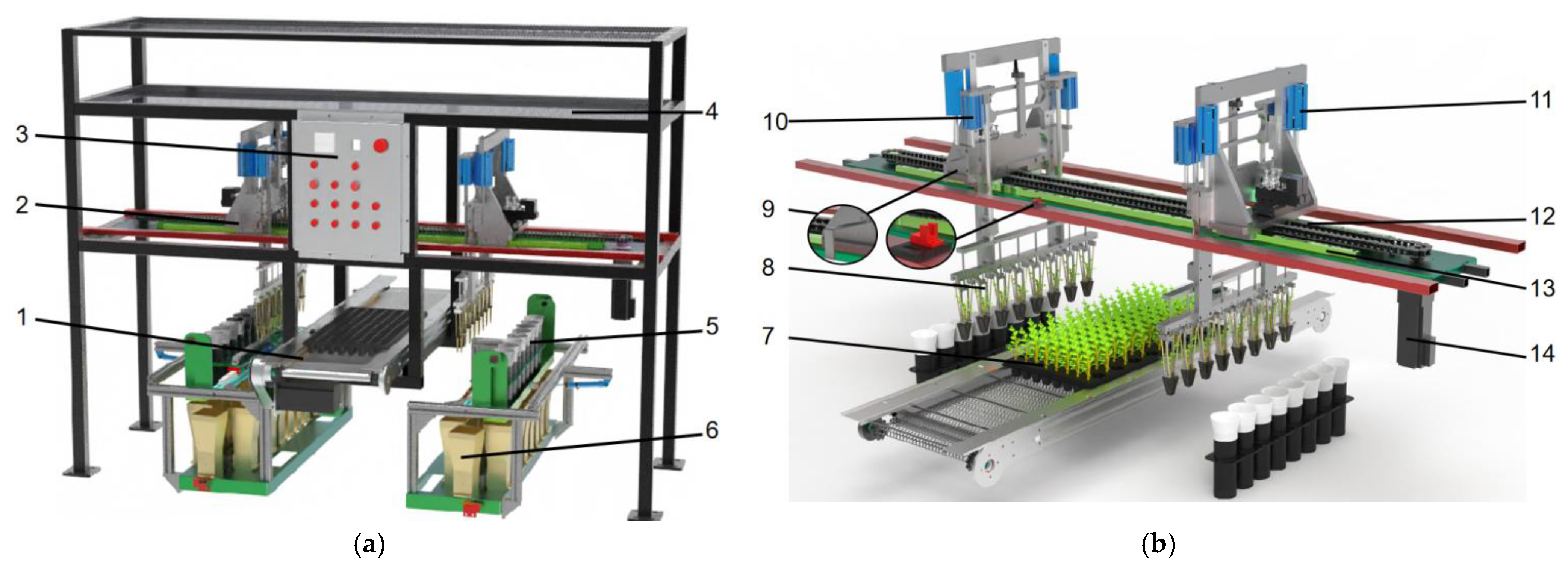
2.1. The Structure Composition of the Dual-Row Seedling Pick-Up Device

The seedling picking and throwing system of the automatic transplanting machine includes a seedling pick-up device, seedling tray conveying mechanism, variable spacing seedling separation mechanism, rotating seedling separation mechanism, and a control system, as shown in Figure 1a.
The automatic seedling pick-up device is the core working component of the transplanting machine, as shown in Figure 1b. The seedling pick-up device is mainly composed of a servo motor, drive chain assembly, horizontal linear slide rail, pneumatic seedling pick-up end-effector, and seedling pick-up end-effector position sensor. The servo motor drives the end-effector to make a horizontal reciprocating motion between the picking and throwing positions by driving the chain, and the end-effector picks up the seedlings from near to far along the longitudinal direction of the seedling tray.

2.2. Working Principle

(a)
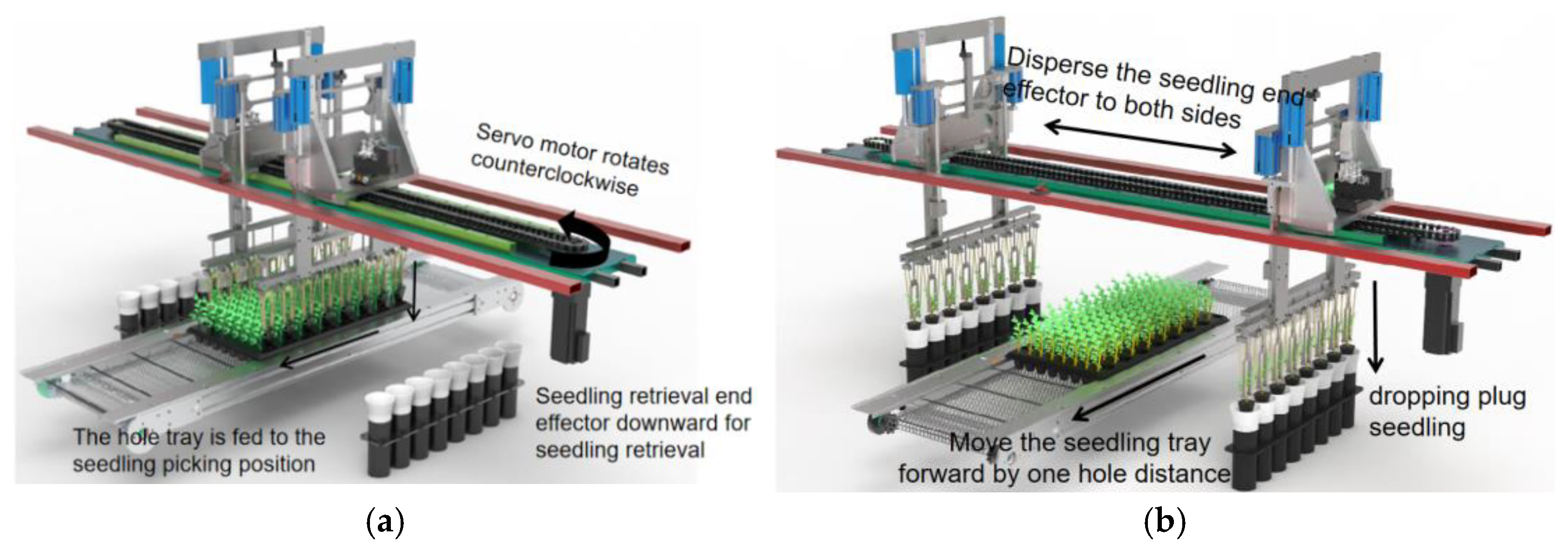
During work, the plug seedlings are placed on the seedling tray conveying device, and the seedling tray will be transported to the seedling picking position by the conveying motor. When the seedling tray reaches the picking position, the seedling pick-up end-effector will be driven by the servo motor to the middle and close above the picking point. The push rod of the lifting cylinder moves downward, and the picking needles will insert into the pot body driven by the push rod, and then the seedling pick-up end-effector will be driven by the lifting cylinder to remove the seedlings to the top of the seedling tray to complete the seedling pick-up action.
(b)
Afterwards, the servo motor rotates in reverse, and the end-effector of the seedling will disperse to both sides to reach the throwing point. The cylinder push rod drives the push seedling ring to move downward, and the pot seedling will be pushed down from the seedling pick-up needle to complete the seedling throwing action. Finally, under the drive of the motor, it returns to the seedling position for the next stage of seedling picking work. The position sensor provides an initial position mark for the end-effector, and after each row of seedlings is picked, the position of the end-effector will reposition based on its position signal, so as to avoid error accumulation and ensure the lateral positioning accuracy of the end-effector on the seedling tray.
Each seedling end-effector component has 8 seedling claws, which can pick up 16 seedlings in one action, making it highly efficient. The movement distance of the seedling end-effector component is calibrated by the reset sensor for the initial position, and the positions for picking up and throwing seedlings are calculated based on the pulse number of the servo motor. The dispersal position of the seedling component can be adjusted arbitrarily through program settings. Depending on the different throwing row spacing of different crops, the dispersal distance between the two end-effectors components can be adjusted within a range of 400 mm to 700 mm (Figure 2).

3. Design of Key Components and Control System

3.1. The Design of the Seedling Pick-Up End-Effector

In order to improve the operation efficiency and quality of the automatic seedling transplanting machine, a pneumatic end-effector with eight seedling claws integrated into one unit was designed.

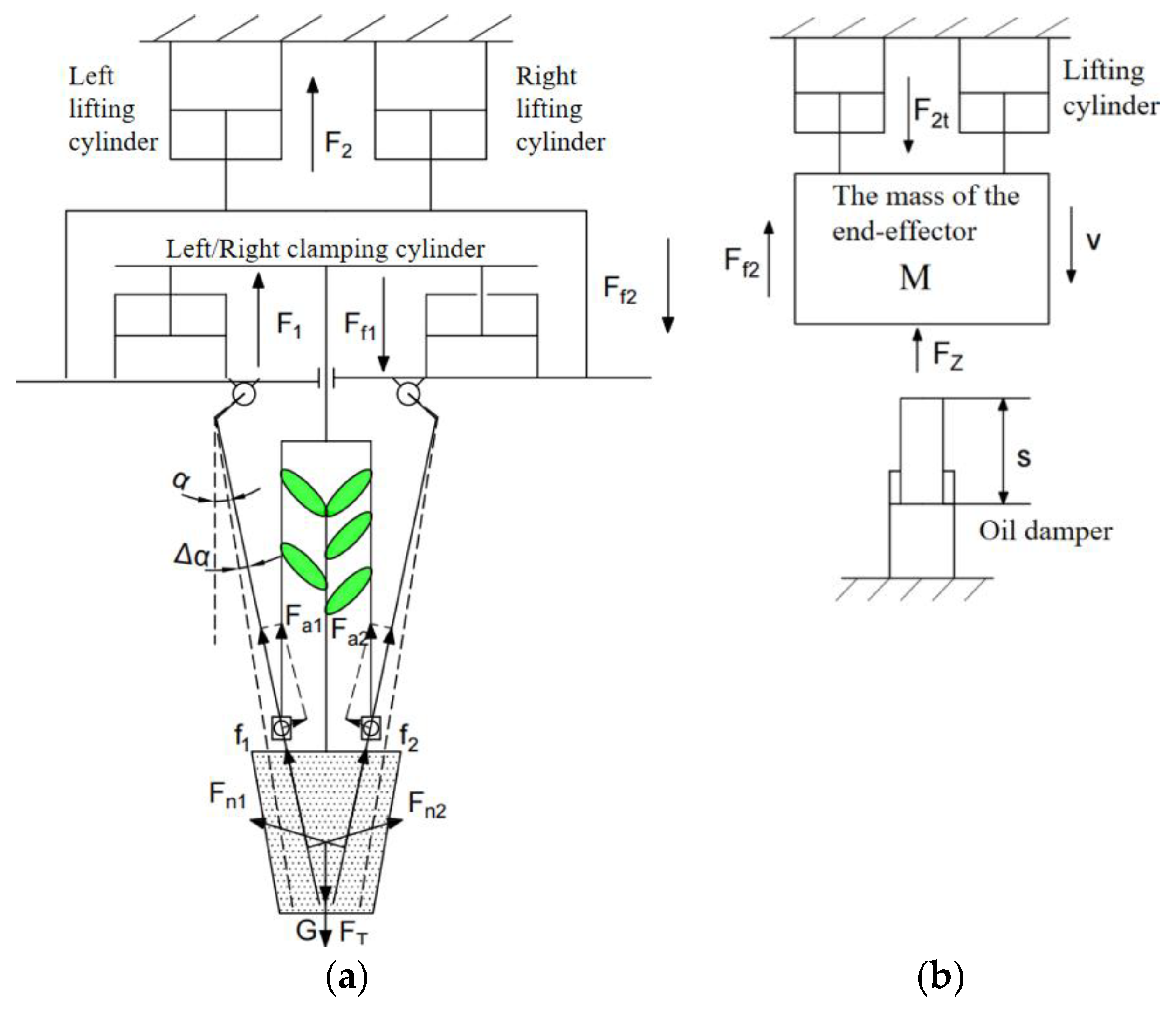
3.1.1. Design of Clamping and Picking Seedlings Action

The structure and process of the end-effector for picking seedlings by clamping are shown in Figure 3. (a) When picking seedlings, the end-effector is positioned above the tray seedlings, and the lifting cylinder moves downward, causing the seedling needle of the end-effector to insert into the pot under the drive of the lifting cylinder. (b) When the descent distance is H1, the seedling needle and the push seedling ring both come into contact with the upper end surface of the pot. At this moment, the push ring moves upward under the drive of the clamping cylinder. Since the clamping cylinder and the push ring are mounted on the lifting plate, they continue to move downward under the drive of the lifting cylinder. When the descent speed of the lifting cylinder is the same as the ascent speed of the clamping cylinder, the push ring remains stationary relative to the upper end surface of the pot, while the seedling needle continues to insert into the interior of the pot. (c) At this moment, the movement of the push ring relative to the seedling needle is backward, and the seedling needle relies on the hinge mechanism to move towards the center and generate tightening force to clamp the seedling pot, which completes the clamping action on the pot seedlings. When the end-effector is fully inserted and clamped onto the pot, it briefly pauses. (d) Then, under the drive of the lifting cylinder, the end-effector removes the seedling pot to above the seedling tray to complete the seedling picking.
The seedling needle was inserted into the seedling pot at an angle of α. In order to prevent the seedling needle from inserting into the side wall of the seedling plate, the angle of α was determined by the taper of the hole, α = 12°. H is the height of the pot, determined by the depth of the hole, with H = 42 mm. H2 is the depth at which the seedling needle is inserted into the pot, based on previous research by the project team on the vertical distribution pattern of roots in the pot. It was found that the root density is the lowest at a two-thirds depth of the pot; to prevent breakage and damage at this point, the insertion depth should exceed the fracture zone, with H2 = 40 mm. H1 is the initial position of the end-effector from the upper end surface of the pot, determined by the stroke of the lifting cylinder.

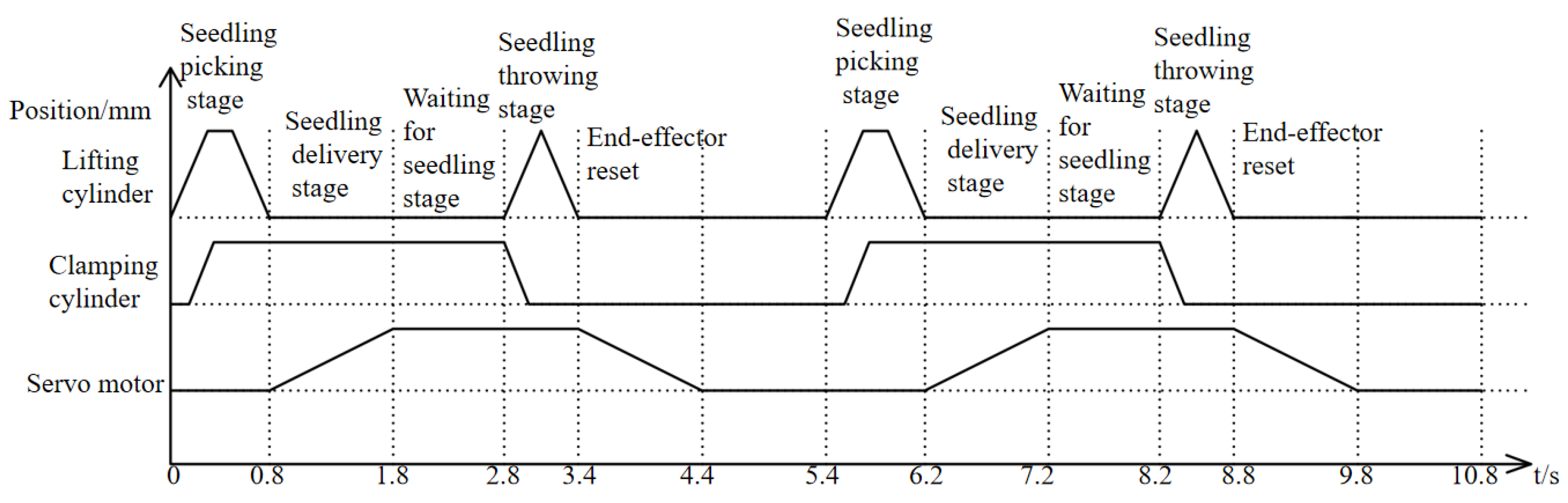
3.1.2. Design of Timing Control of Picking and Throwing Seedlings

According to the design requirements of the maximum transplanting speed of 90 plants/row·min−1, eight seedling claws were used to pick up seedlings synchronously, and the whole seedling period was T = 5.4 s. Figure 4 shows the action timing diagram of each actuator component, with time on the x-axis and the position of each actuator component on the y-axis. From the first retraction of the lifting cylinder piston rod to 0 mm to the fourth retraction to 0 mm, a working cycle is completed, with the total action cycle time being 5.4 s. It is important to note that if the lifting cylinder speed is greater than the clamping cylinder speed, the seedling ring will press down on the pot, causing compression damage. If the lifting cylinder speed is slower than the clamping cylinder speed, the seedling needle will complete the clamping action prematurely, causing internal compression damage to the substrate inside the pot. Therefore, it is necessary to maintain equal speeds between the lifting cylinder and the clamping cylinder during the seedling picking process.

3.1.3. Analysis and Selection of Cylinders

The working parameters of the seedling end-effector and the design of the seedling picking process should be based on the characteristics of the object, including the shape and size of the holes, as well as the mechanical properties of the seedling tray [27,28]. The seedling claw adopts a two-finger-four-needle structure, and the force analysis is carried out on a single seedling claw. At the moment when the end-effector picks up the seedling tray and starts to move upwards, the force analysis is shown in Figure 5a.
In order to ensure the friction force generated by seedling picking against the pot overcomes the adhesion force F T generated by the hole of the pot and the gravity G of the pot, the following formula needs to be satisfied, Equation (1).
2 F n 1 + F n 2 sin α + Δ α + 2 f 1 + f 2 cos α + Δ α F T + G
where F n 1 and F n 2 are the positive pressure exerted by the single-sided seedling needle on the pot body, N; α is the angle formed by the seedling needle and the vertical direction, (°); f 1 and f 2 are the frictional forces generated by the seedling needle on the pot body, N.
For the force analysis of the seedling needle, the seedling needle is subjected to the reaction force of the pot body and the upward force F a 1 and F a 2 (the component forces generated by the clamping cylinder). Formula (2) can be listed based on the principle of force balance.
F a 1 s i n α + Δ α = F n 1 F a 2 s i n   α + Δ α = F n 2
Assuming that the seedling pot is a homogeneous material structure, then F n 1 = F n 2 , f = µ F n , and combining Equations (1) and (2), we can obtain the following:
F a 1 = F a 2 F T + G 4 ( sin ( α + Δ α ) + μ cos ( α + Δ α ) ) sin ( α + Δ α )
G is the weight of the pot, N; F T is the adhesive force generated by the holes on the pot, N.
In the previous study, our research group calculated that the adhesion of a seedling can be overcome only by providing an output force greater than 22.5 N [29]. The output force of the clamping cylinder is determined by the cylinder diameter and working air pressure, satisfying the formula
F 1 = 2 P π D 1 2 d 2 2 4   F f 1 + 8 F a 1 + F a 2 = 196   N
where F 1 is the output force of two clamping cylinders, N; P is the working air pressure, 0.3 MPa; D 1 is the inner diameter of the clamping cylinder, mm; d 1 is the diameter of the piston rod of the clamping cylinder, mm. F f 1 is the frictional force generated when resisting the upward movement of the push ring, measured as 16 N.
F 2 F f 2 + 8 G + F T + M g = 105   N
where F 2 is the contraction force of the lifting cylinder, N; F f 2 is the friction force overcome by the end-effector during upward movement, measured at 34 N; M is the mass of the end-effector, 4.8 kg; g is the acceleration due to gravity, 9.8 m/s2.
To ensure the smooth operation of the seedling picking action, the clamping cylinder and the lifting cylinder are symmetrically installed on both sides in terms of structure, ensuring equal force on both sides. Through the force analysis above, the thrust range of the cylinder can be determined. Based on the principle of seedling picking and clamping, the stroke size of the cylinder can be determined. Under the premise of a working pressure of 0.3 MPa, the SDA25×50S cylinder is chosen as the clamping cylinder, and the SDA32×70S cylinder is chosen as the lifting cylinder. The output force provided by the cylinders meets Formulas (4) and (5).

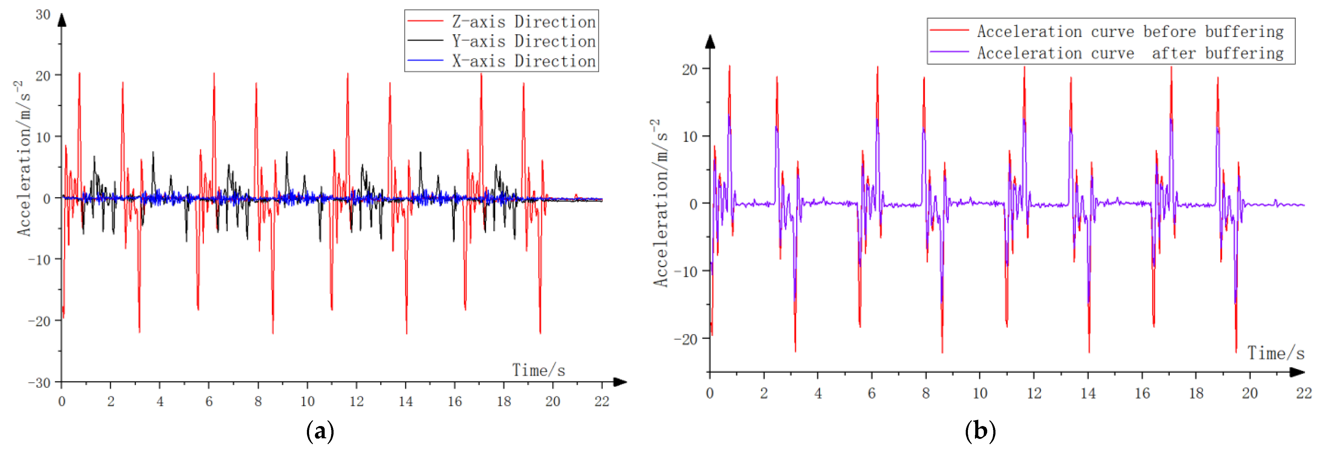
3.1.4. Analysis and Design of Buffers

The lifting cylinder will generate an inertia impact phenomenon at the end of operation, especially when the end-effector is picking up seedlings downwards, and the work conducted by the weight of the end-effector will exacerbate the generation of end impact vibration. In order to reduce the damage to the seedling tray caused by the impact kinetic energy, it is necessary to design a buffer for the end of the lifting operation. The buffer is a protective device used to reduce mechanical impact, utilizing the throttling damping effect of hydraulic oil to produce a buffering effect, extending the time of impact load, dissipating impact energy, thereby smoothly decelerating the equipment during operation, and achieving the buffering purpose [30], as shown in Figure 5b.
When the lifting cylinder pushes the end-effector downwards, the buffering work required is determined by the lifting cylinder thrust, frictional force, and the weight of the end-effector, satisfying the formula
F H = F 2 t + M g F f 2 F Z = 415   N
where F H is the total force for work, N; F 2 t is the thrust of the lifting and lowering cylinder, N; F Z is the resistance generated when the seedling needle is inserted into the pot, N.
The total energy that needs to be buffered includes the kinetic energy of the end-effector and the driving energy, satisfying the following formula
E T = E K + E D = M   v 2 2 + s F H s i n θ
where E T is the total energy that needs to be dissipated, J; E K is the kinetic energy at the end of the actuator buffering moment, J; E D is the work conducted by the resultant force, J; v is the impact velocity during the buffering moment, 0.4 m/s; s is the buffering stroke, mm; θ is the inclination angle of the buffer, 90°.
Based on the total energy that needs to be buffered and the buffer stroke required, a suitable buffer device can be designed. Here, the ACA1210 model hydraulic buffer with a buffer stroke of 10 mm and a maximum absorption energy of 10 J is chosen for buffering. The types and operating parameters of the cylinder and buffer are shown in Table 1.

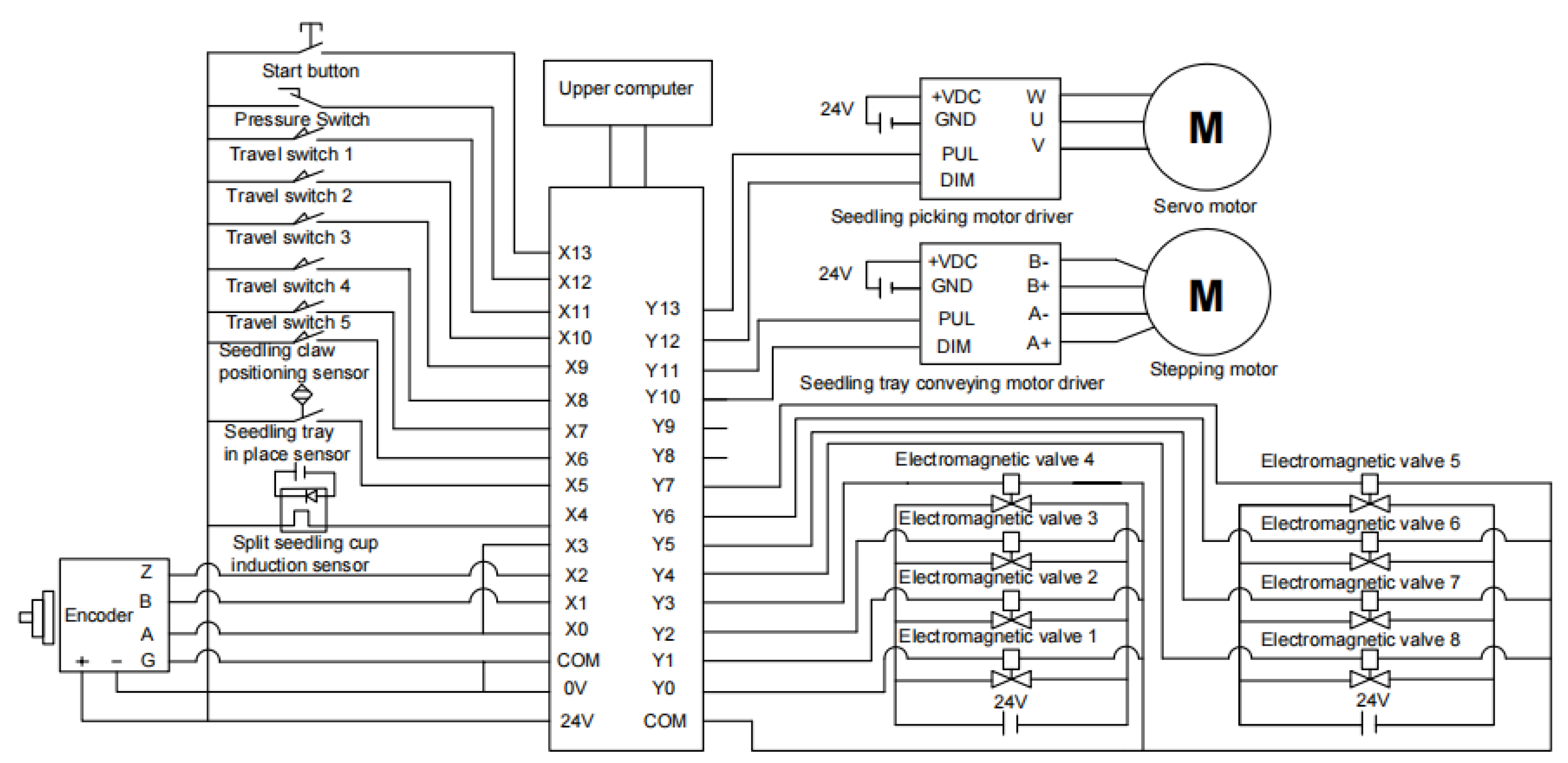
3.2. Design of Control Systems

3.2.1. Design of Control System Hardware

The sports coordination control system is mainly composed of a PLC controller, seedling picking servo motor and its driver, seedling tray conveying stepper motor and its driver, end-effector position sensor, seedling tray position sensor, encoder, seedling pick-up end-effector downward/upward position travel switch, the lifting cylinder, clamping cylinder, dispersing cylinder solenoid valves, etc. The electrical connection relationship is shown in Figure 6.
The PLC controller adopts XINJIE XD5-48T6-E, and the picking servo motor adopts the MS-60ST-M01330 servo motor (XINJIE, Wuxi, China), which is equipped with a servo motor driver (DS3E-20P4-PFA). The disc-moving stepper motor adopts the SDGA-01C31AB stepper motor (TODE, Shenzhen, China), which is equipped with the TSDA-C21B stepper motor driver (TODE). The PLC controller receives high-speed pulse count signals from the encoder input, end-effector position sensor signals, seedling pick-up end-effector position switch signals, and switch signals from the seed cup counter sensor, and it outputs high-speed pulse control to coordinate the motion of the picking servo motor and the seedling tray conveying stepper motor. The electromagnetic valves of various pneumatic components are controlled by the PLC output signals through relays. In order to respond quickly to each clamping action, the position information of the pneumatic actuator is detected, and the detection signal of the magnetic switch is used as the trigger signal to start the next execution action so that the seedling end-effector has the induction ability.

3.2.2. Design of Control System Solution

The main program flow of the control system is shown in Figure 7. The motion parameters include the stroke s , which represents the distance that the servo motor drives the end-effector to move from the picking position to the throwing position; the speed parameter v is the frequency of control pulses for the servo motor, which determines the moving speed of the end-effector; the row counter n1 is used to count the number of seedlings that have been picked from a tray; the seedling cycle counter n2 is used to count the number of picking cycles; the column counter n3 is used to count the number of columns picked in a tray. The machine is compatible with 128 (8 × 16)-hole seedling trays, with a total of eight columns. Since the seedlings are picked in double rows, the effective number of columns is from one to four, and the initial values of all counters are zero. For each tray of seedlings, the end-effector picks them from outside to inside, so the initial value of the stroke s corresponds to the linear distance from the seed tube to the nearest column of seedlings, which is 400 mm. Every time a row of pot seedlings is picked, the stroke s must be corrected to locate the end-effector to the next column of seedlings.
After the system boots up and initializes, the servo motor drives the end-effector to move towards the center and then reverses to above the seedling tubes after triggering the rest sensor, completing the reset action. The stepper motor drives the seedling tray forward, and after triggering the seedling tray position sensor, it slows down and travels a certain distance to reach the seedling picking position. Then, the servo motor drives the end-effector to move to the seedling picking position, reaching directly above the nearest row of seedling pots.
The PLC controls the electromagnetic value of the lifting cylinder to be turned on, and the two seedling end-effectors move down together. After the end-effector triggers the downward position switch, the PLC controls the clamping cylinder electromagnetic valve to be turned on, and the seedling needle in the end-effector extends and inserts into the hole, clamping the seedling. The system controls the electromagnetic value of the lifting cylinder to be turned off, and the two end-effectors move up together. After triggering the upward position switch, the PLC controls the servo motor to drive the two end-effectors to the throwing position according to the stroke s and speed v , and the seedling pick-up action is completed at one time.
After the end-effector reaches the throwing position, the PLC controls the electromagnetic value of the clamping cylinder to be turned off, the seedling needle retracts into the end-effector, and the seedlings fall into the merging state dispersing tube under gravity, completing the throwing action. After the throwing is completed, the servo motor drives the end-effector to move towards the center and start the next pick-and-plant cycle.
For every eight seedlings taken out, the row counter was added with eight, and the seedling number counter added with one. At this point, it is judged whether the number of seedlings is odd or even. If it is odd, the seedling tray moves forward by the distance of one hole so that the eight seedlings that have not been removed in the same column correspond one-to-one with the eight seedling claws of the end-effector, making it convenient for the next seedling retrieval. If it is even, the seedling tray moves back by a distance of one hole. If the row counter has been added to 16, it indicates that the column of seedlings has been completely taken out. The row counter is reset to zero, the column counter is added to one, and the PLC controls the servo motor to drive the seedling end-effector to the next column of seedlings. At this point, the travel distance s increases by the distance of one hole, 32 mm. If the column counter has been added to four, it indicates that all seedlings in the seedling tray have been taken out. The column counter is reset to zero, and the PLC controls the stepper motor to drive the seedling tray to feed at high speed, and after triggering the seedling tray in place sensor, it slows down for a certain distance, thus completing the connection and positioning of the two seedling trays.

3.2.3. Setting of Operating Parameters of Seedling Servo Motor

According to the requirements of the system for the speed of seedling picking, the motion parameters are determined through actual operation and debugging. The maximum one-way running distance of the seedling pick-up mechanism is the distance from the fourth column of seedlings to the throwing position, with a running distance of s = 400 + 3 × 32 = 496 mm, and the running time is T. Calculated based on the high-speed transplanting speed of 90 plants/row·min−1, the average seedling picking cycle is T = 5.4 s. Considering that multiple aerodynamic actions such as the end-effector moving downward, the seedling needle clamping, the end-effector moving upward, and the seedling needle recovering all require a certain amount of time and cannot be overlapped, the completion time reserved for each action is shown in Figure 4. At the same time, the waiting time for picking and throwing seedlings is increased by 1 s each, and the maximum speed of the one-way movement of the end-effector driven by the servo motor is as follows:
v = 2 s T 0.8 0.6 2 = 496   m m / s
The model of the drive sprocket is 08B-12, with a pitch circle diameter of D = 49.07 mm; the maximum speed of the servo motor is
n = 60 v π D = 193.0   r / m i n
The control frequency of servo motor operation is
H = 2500 n 60 = 8041   H z
where 2500 is the number of pulses sent by the PLC when the MS-60ST-M01330 servo motor (XINJIE, Wuxi, China) rotates one circle.
The number of pulses emitted by the PLC when the seedling pick-up machine moves is
N = s + 32 n 3 θ 360 π D
where θ represents the stepping angle (°) of the servo motor, with θ = 0.144°; n 3 represents the data recorded by the row counter, with valid column numbers ranging from one to four.
The servo motor is the core component of the seedling pick-up mechanism, and its operating accuracy directly determines the performance of seedling picking. The working principle is to convert pulse signals into angular displacement. Equipped with a high-precision encoder, it is a closed-loop system with high operating accuracy, but it also requires that the impact during the start and stop stages should not be too large. Especially in the case of a row of a multi-claw seedling pick-up device with large mass and high motion inertia, it can cause a decrease in the accuracy of seedling picking position control. Therefore, by designing a reasonable motor start–stop control algorithm, the positioning accuracy of the motor can be improved [31,32].
The commonly used motor start–stop control algorithms currently include trapezoidal curve, exponential curve, and S-curve algorithms. The S-curve control algorithm is a control algorithm that can achieve smooth acceleration and deceleration processes [33]. It can effectively reduce the impact on the load and improve the accuracy and response speed of the system. The S-curve algorithm has the characteristic of continuous control, with no sudden changes in the motor’s speed and acceleration and is often used in precise control. In this paper, the S-curve start–stop control algorithm is used to control the motor.
The formula for the start-up phase of an S-curve is
H i = H s t a r t + H s e t H s t a r t 1 + e k ( i u ) / u
where Hi represents the current control frequency of the motor (Hz); Hstart represents the starting frequency (Hz); Hset represents the running set frequency (Hz); k represents the curve coefficient; u represents the number of pulses in the starting stage.
According to the calculation of the operating frequency of the servo motor in this paper, a frequency of 8041 Hz is selected. The start frequency is set to 0 Hz. The parameter k determines the acceleration magnitude in the middle area of the S-curve. The larger the k value, the greater the acceleration, and the smaller the k value, the closer it is to uniform acceleration. The value of k is generally between 3 and 7. To make the start phase symmetrical, the value of u is set to half of the total number of pulses in the start phase, which is set to 2000 pulses, so u is set to 1000.
During the start-up phase, the control frequency of the servo motor gradually increases from the start-up frequency to the set operating frequency and is symmetrically distributed around the center of the curve. The frequency acceleration goes from zero to the maximum value and then back to zero. This change process makes the acceleration and deceleration of the motor a slow and gradual process, greatly reducing the impact issues during motor start-up–stop phases and improving the position control accuracy of the motor.
The process of the motor stopping stage is symmetrical to the starting stage, with the formula for the S-curve stop stage
H i = H s e t H s e t H s t o p 1 + e k ( i u ) / u
where H s t o p is the stop frequency, set to 0. Other parameters, stop stage operation principles, and operating parameters are the same as the start stage.

4. Experiments and Results

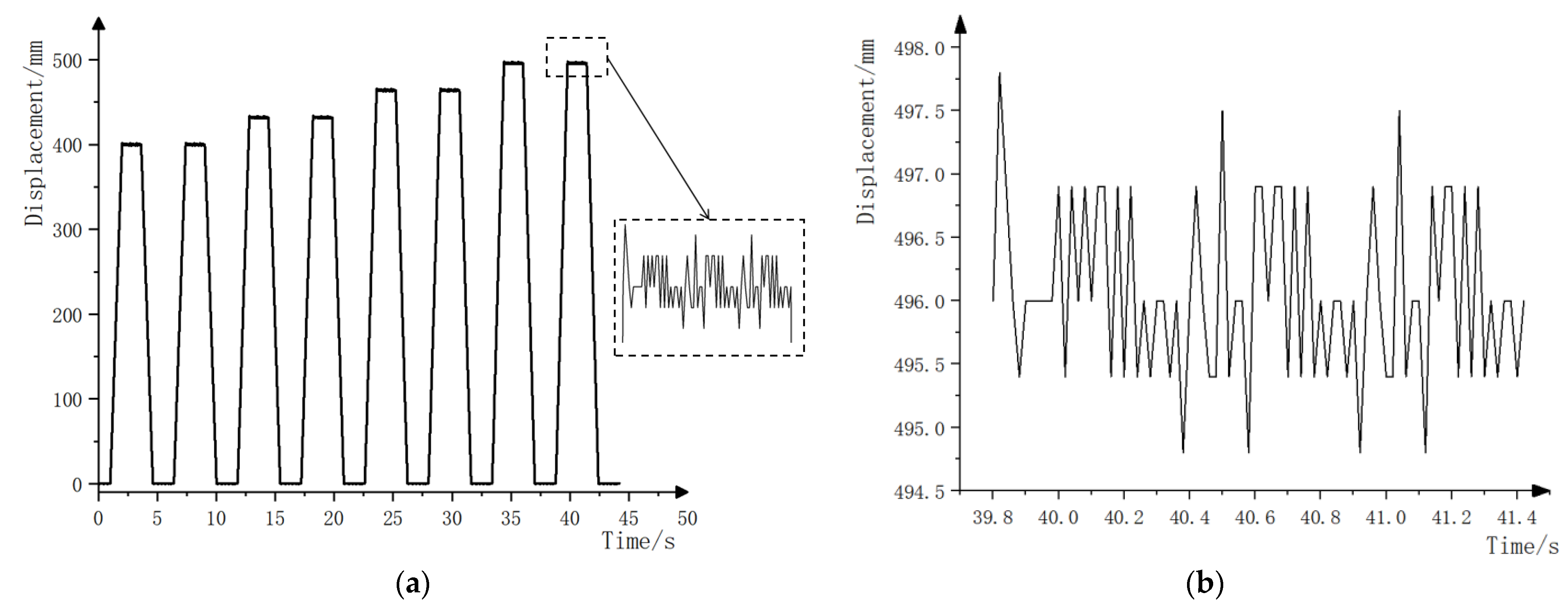
4.1. Experiment on Displacement Accuracy and Operation Stability of Seedling Picking and Throwing Mechanism

4.1.1. Design of Experimental Scheme

To evaluate whether the positioning accuracy and operational stability of the seedling pick-up mechanism meet the requirements of the transplanting machine operation, a positioning accuracy test of the seedling picking displacement was conducted. The 1A340E triaxial accelerometer and DH5902 dynamic data acquisition instrument were used to collect the triaxial acceleration of the seedling picking mechanism at the set pulse frequency. The linear displacement measurement system, consisting of a KTC-500 pull rod linear displacement sensor, BZ2204A plug-in transmitter module, and BZ7201 data acquisition instrument, was used to measure the horizontal positioning accuracy of the seedling picking mechanism at the set pulse frequency. The instruments used are shown in Table 2.
The linear displacement sensor is installed on the frame of the seedling pick-up mechanism, with its telescopic rod connected to the end-effector along the horizontal displacement direction. By driving the end-effector, the telescopic rod of the linear displacement sensor is extended and retracted, causing a change in the resistance and pressure of the linear displacement sensor, ultimately converting the linear mechanical displacement into an electrical signal to detect the actual dynamic characteristics of the transplanting machine. Before application, the relationship between the mobile displacement and the measured voltage signal of the linear displacement detection system is calibrated, with a sampling frequency of 200 Hz. The triaxial accelerometer is connected to the end-effector with a sampling frequency of 50 Hz. The built acceleration testing system and displacement testing system are shown in Figure 8.

4.1.2. Experimental Results and Analysis

Figure 9a shows the relationship between the displacement of the seedling end-effector and time. The seedling pick-up cycle is 5.4 s. Two end-effectors can pick 16 seedling pots at a time. For 128-hole seedlings, it requires eight movements to pick the entire tray. For every two picks, the overall displacement of the end-effector increases by 32 mm (the distance of one hole). The end-effector is driven by a servo motor for movement, and pneumatic action is used for seedling picking and throwing. During the seedling picking and throwing process, high-frequency vibrations are generated by the pneumatic and servo motor, which appear as noise signals at the seedling picking and throwing points on the data graph. However, the system runs smoothly with a smooth curve during the movement of the end-effector, indicating that the selected controller and servo motor control parameters are well set. It is important to adjust the smoothness of the pneumatic impact and motor start-up at the seedling picking and throwing points. Through practical testing and analysis, the reliability of the designed automatic seedling picking and shifting system has been verified, and it can accurately achieve the function of picking and shifting the seedlings in the holes. The positioning error of the seedling end-effector is between 0.5 mm and 1.8 mm within its stroke, with the maximum error of 1.8 mm occurring at the moment when the servo motor-controlled end-effector stops. Once the seedling end-effector stabilizes, the positioning error stabilizes at 0.5–0.9 mm. The design positioning error requirement of this transplanting machine is to be controlled within ±2 mm, which meets the transplanting positioning accuracy requirements.
Figure 10 shows the graph of acceleration versus time in the triaxial direction of the end-effector. When the triaxial acceleration sensor detects that the acceleration was greater than 1 m/s2, the date was recorded. The graph shows data from four seedling picking cycles. The Z-axis represents the direction of the lifting cylinder, with vertical downward as the positive direction. The X-axis is aligned with the direction of the seed tray, with the direction towards the seed tray as the positive direction. The Y-axis represents the direction of movement of the end-effector, with the direction pointing to the throwing position as the positive direction. The blue curve represents the acceleration change in the X-axis direction. Since there were no moving parts in this direction, the acceleration change tended to be a horizontal line. However, due to high-frequency vibration signals generated during machine operation, the acceleration range was between −1.37 m/s2 and 1.42 m/s2. The black curve represents the acceleration change curve in the Y-axis direction, which was influenced by the start and stop of the servo motor. Its acceleration change range was larger compared to the X-axis, ranging from −7.15 m/s2 to 7.52 m/s2. Due to the light weight of a single seedling tray, this was converted into the impact force on the tray when taking seedlings
F Y = m a = 0.013 × 7.52 = 0.098   N
The impact of acceleration in this direction on the seedling tray can be ignored, indicating the stable operation of the servo motor. The red curve represents the acceleration change curve in the Z-axis direction. Due to the impact of the lifting cylinder at the end of operation, the acceleration range was −22.1 m/s2 to 20.28 m/s2. Compared to the peak accelerations in the other two directions, a buffer design was needed in the Z-axis direction to reduce the damage to the seedlings inside the tray. Figure 10b shows the comparison of the acceleration curve changes before and after the buffer design in the Z-axis direction of the end-effector. It can be seen from the figure that the buffer design significantly reduced the peak acceleration; especially the maximum peak value decreased from −22.1 m/s2 to 13.4 m/s2, and the peak value was reduced by 39.4%. The optimization results were significant, which effectively reduced the impact force of seedling picking on the pot body, thereby reducing the damage inside the pot body. The optimization did not affect the timing of the seedling picking action and improved the reliability of seedling picking and throwing while ensuring the realization of the seedling picking action. This provides a reference for future optimization designs of the end-effector.

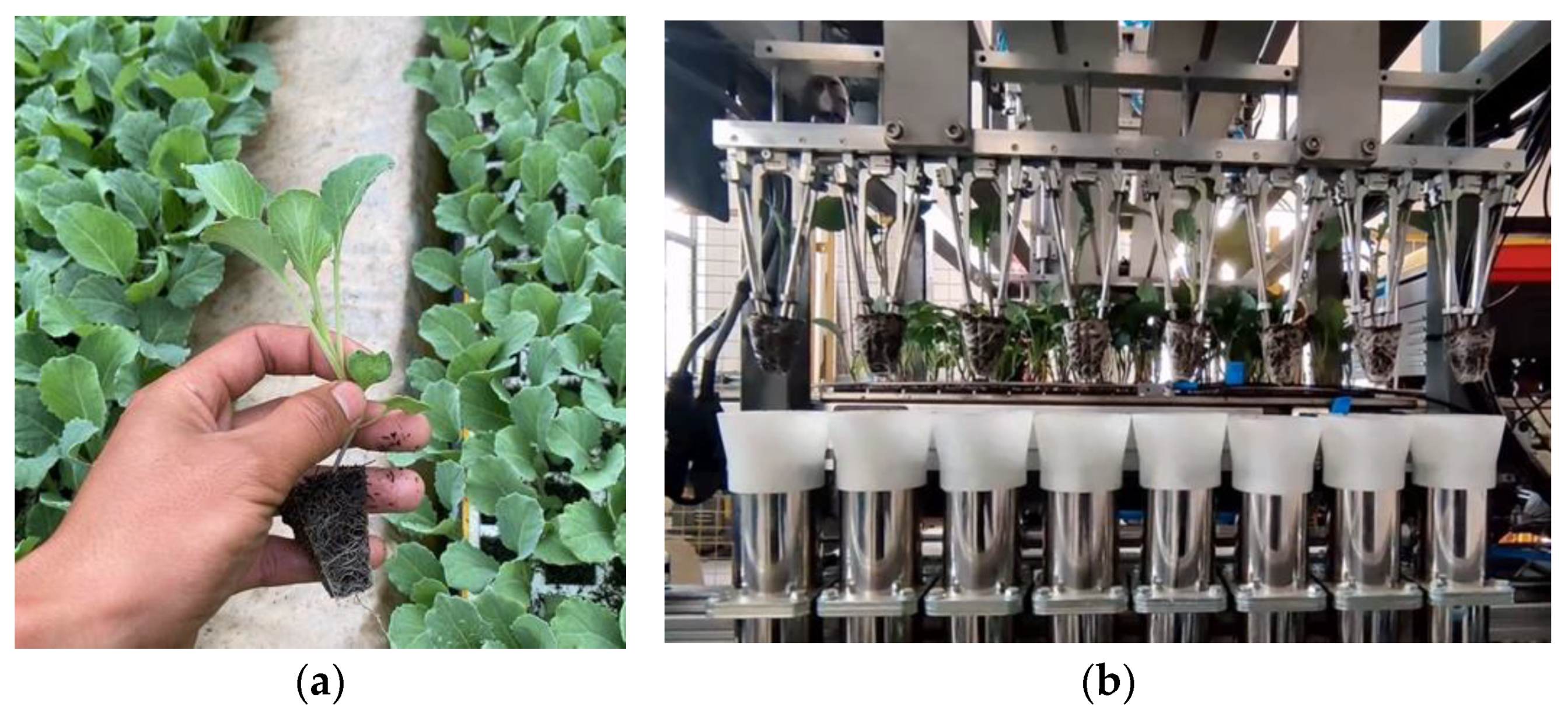
4.2. Performance Test of Seedling Picking

4.2.1. Experimental Design and Evaluation Criteria

In order to further verify the rationality of the design of the seedling picking and throwing system, the performance test was conducted at the Key Laboratory of Modern Agricultural Equipment at Jiangsu University, as shown in Figure 11b. The test object was a 128-hole cabbage seedling tray, the water content of the pot body was (60 ± 5)%, and the seedling age was 33 days. At this time, the cabbage seedlings had grown to four leaves and one heart, and the height of the pot seedlings was 130–150 mm, as shown in Figure 11a. Referring to the industry standard JB/T 10291-2013 [34], the requirement for high-speed transplanting efficiency is 90 plants/row·min−1. The seedling picking and throwing efficiency of the system was set at 180 plants/min for continuous testing, and the test results were recorded and analyzed [35].
According to the seedling picking process, the success rate of seedling picking S Q , the success rate of seedling throwing S T , the damage rate of seedling pot S S , and the comprehensive success rate of seedling picking and throwing S are used as experimental evaluation indicators. The mechanical standards for dryland planting stipulate that when the seedlings planted are damaged and affect their normal growth, they become injured seedlings. For vegetable plug seedlings, puncturing the leaves with a needle will not have a significant impact on the later growth of the seedlings. In the data, only more than half of the broken seedlings were counted as damaged seedlings. The calculation formula is as follows
S Q = N 1 N 0 × 100 %
S T = N 2 N 1 × 100 %
S S = N 3 N 0 × 100 %
S = ( S Q × S T S S ) × 100 %
where N 0 represents the total number of seedlings picked; N 1 represents the number of seedlings that the end-effector failed to pick out from the seedling tray; N 2 represents the number of seedlings that the end-effector failed to successfully throw after picking them out; N 3 represents the number of damaged seedlings.

4.2.2. Analysis of Test Results

According to the experimental results (Table 3), it could be seen that under a seedling efficiency of 180 plants/min, the comprehensive success rate of seedling picking and throwing for 128-hole trays was above 95%. Among them, the number of unextracted seedlings in the cell trays was the highest, reaching 2.1%. When the unextracted seedlings were pushed out from the holes, it was found that these seedlings had fewer root systems, and the roots were not tightly wrapped around the substrate from the bottom to the top of the hole. The breaking of the seedling pots was due to the loose wrapping of the roots, with only a clump of substrate taken out from the main root area of the seedling stem, leaving most of the seedling pots inside the holes. Due to the bending growth of a few seedlings, when picking seedlings downward, it was easy to press and break the stems of the seedlings, leading to stem breakage. The success rate of throwing seedlings was close to 100%. During the experiment, only a few seedling pots had a large crown expansion due to the bending growth of the stem, and the leaves were entangled in the end-effector of the seedling pick-up, which could not be accurately released at a fixed point.
The average success rate of seedling picking and throwing was 97.3%, indicating that the designed automatic seedling picking and throwing system can better grab seedlings from the plug and transfer them to the seedling throwing position to complete the seedling throwing. However, it is still necessary to improve the seedling transplanting technology system from horticultural conditions and mechanical factors. The use of dwarf seedlings with developed roots is conducive to production operations.

5. Conclusions

(1)
The seedling pick-up device developed in this paper combines mechanical structure with automatic control principles. To reduce the damage of the mechanical end-effector to the pot seedlings and improve the reliability of seedling picking, a flexible pneumatic seedling pick-up end-effector was designed through the mechanical analysis of the end-effector and the pot body and the buffer optimization analysis of the end-effector, which can take 16 pot seedlings at one time. By coordinating the lifting cylinder and clamping cylinder, the seedling damage was effectively reduced, while the efficiency of seedling picking was improved. A row picking and throwing motion control system was designed based on the PLC, which monitored the picking and throwing process through various sensors, optimized the operation parameters of the servo motor, and achieved the goal of low-speed and efficient seedling picking.
(2)
In order to evaluate whether the positioning accuracy and operation stability of the seedling picking mechanism can meet the requirements of transplanting machine operation, a dynamic signal acquisition system and a linear displacement sensor were used to conduct positioning accuracy tests on the seedling displacement. The results showed that within the stroke of the seedling pick-up end-effector, the positioning error remained stable at 0.5–0.9 mm, which meets the requirements of transplanting positioning accuracy. Using 33-day-old cabbage plug seedlings as the test objects, seedling picking and throwing performance tests were conducted at an efficiency of 180 plants/min. The results showed that the comprehensive success rate of seedling picking and throwing was above 95%, with an average success rate of 97.3%. The designed automatic seedling picking and throwing system can effectively pick up seedlings from the plug tray. The coordination of the various components of the machine during operation is good, meeting the technical requirements of the fully automated mechanical transplanting of plug seedlings.
(3)
Certainly, the dual-row seedling pick-up mechanism proposed in this paper has certain limitations in practical applications. It can only be applied to the transplantation of 128-hole tray seedlings and cannot achieve dense transplantation in multiple rows. However, it possesses certain innovative structural features and the integration of electrical control methods, which carry valuable implications for future development. Compared to existing seedling extraction mechanisms, this mechanism can complete the transplantation of 16 bowl seedlings within one extraction cycle. While ensuring high-speed transplantation, it prolongs the seedling picking cycle, achieves low-speed operation, and reduces the impact damage of the seedling picking mechanism on the bowl body. Effectively solving the problems of the low efficiency of single end-effector seedling retrieval and the significant inertia impact of multiple end-effectors, it can provide reference for the research of high-speed fully automatic transplanting machines for hole tray seedlings.

Author Contributions

Conceptualization, R.Y. and J.H.; methodology, R.Y., J.H. and M.Y.; software, R.Y. and J.Z.; validation, R.Y. and J.H.; formal analysis, R.Y., J.H. and M.Y.; investigation, R.Y. and T.Z.; resources, J.H.; data curation, R.Y. and J.S.; writing—original draft preparation, R.Y.; writing—review and editing, R.Y., J.H. and M.Y. All authors have read and agreed to the published version of the manuscript.

Funding

This work was supported by Shanghai Green leafy Vegetable Industry Technology System Construction-Development and Application of Key Technologies for high-density green Leafy Vegetable transplanting [Shanghai Nongke (2023) No. 2], Jiangsu Province Agricultural Science and Technology Independent Innovation Fund Project (CX (22)2022), Jiangsu Province Key Research and Development Plan-Modern Agriculture Project (BE2021342). A Project Funded by the Priority Academic Program Development of Jiangsu Higher Education Institutions (No. PAPD-2023-87).

Data Availability Statement

The data presented in this study are available on request from the corresponding author.

Conflicts of Interest

The authors declare no conflicts of interest.

References

  1. Jorg, O.J.; Sportelli, M.; Fontanelli, M.; Frasconi, C.; Raffaelli, M.; Fantoni, G. Design, development and testing of feeding grippers for vegetable plug transplanters. AgriEngineering 2021, 3, 669–680. [Google Scholar] [CrossRef]
  2. Pérez-Ruiz, M.; Slaughter, D.C. Development of a precision 3-row synchronised transplanter. Biosyst. Eng. 2021, 206, 67–78. [Google Scholar] [CrossRef]
  3. Jin, Y.; Liu, J.; Xu, Z.; Yuan, S.; Li, P.; Wang, J. Development status and trend of agricultural robot technology. Int. J. Agric. Biol. Eng. 2021, 14, 1–19. [Google Scholar] [CrossRef]
  4. Yu, G.; Wang, L.; Sun, L.; Zhao, X.; Ye, B. Advancement of mechanized transplanting technology and equipments for field crops. Trans. Chin. Soc. Agric. Mach. 2022, 53, 1–20. [Google Scholar]
  5. Ji, J.; Cheng, Q.; Jin, X.; Zhang, Z.; Xie, X.; Li, M. Design and test of 2ZLX-2 transplanting machine for oil peony. International J. Agric. Biol. Eng. 2020, 13, 61–69. [Google Scholar] [CrossRef]
  6. Hu, Q.; Zhang, Q.; Li, X.; Wan, X.; Wang, L.; Liao, Q. Design and parameter analysis of seedling collection device of rapeseed substrate block seedlings transplanter machine. Trans. CSAE 2021, 37, 18–27. [Google Scholar]
  7. Park, S.-H.; Kim, J.-Y.; Choi, D.; Kim, C.; Kwak, T.; Cho, S. Development of walking type Chinese cabbage Transplanter. J. Biosyst. Eng. 2005, 30, 81–88. [Google Scholar] [CrossRef]
  8. Han, C.; Hu, X.; Zhang, J.; You, J.; Li, H. Design and testing of the mechanical picking function of a high-speed seedling auto-transplanter. Artif. Intell. Agric. 2021, 5, 64–71. [Google Scholar] [CrossRef]
  9. Zhou, M.; Wei, Z.; Wang, Z.; Sun, H.; Wang, G.; Yin, J. Design and Experimental Investigation of a Transplanting Mechanism for Super Rice Pot Seedlings. Agriculture 2023, 13, 1920. [Google Scholar] [CrossRef]
  10. Du, X.; Yun, Z.; Jin, X.; Li, P.; Gao, K. Design and Experiment of Automatic Adjustable Transplanting End-Effector Based on Double-Cam. Agriculture 2023, 13, 987. [Google Scholar] [CrossRef]
  11. Jun, W.; Haiyang, Z.; Xin, J.; Jiangtao, J.; Song, G. Design and experiment of seedling bowl clamping force detection system for plug seedling automatic transplanter. Trans. Chin. Soc. Agric. Mach. 2019, 50, 79–87. [Google Scholar]
  12. Xin, J.; Hongbin, S.; Hengyi, Z.; Jiangtao, J.; Bo, Z.; Cheng, L. Development and Experiment of Integrated Vegetable Pot Seedling Picking Jaw Clamping Force Detection Sensor. Trans. Chin. Soc. Agric. Mach. 2023, 54, 175–183. [Google Scholar]
  13. Zhao, S.; Liu, J.; Jin, Y.; Bai, Z.; Liu, J.; Zhou, X. Design and Testing of an Intelligent Multi-Functional Seedling Transplanting System. Agronomy 2022, 12, 2683. [Google Scholar] [CrossRef]
  14. Han, L.; Mao, H.; Hu, J.; Tian, K. Development of a doorframe-typed swinging seedling pick-up device for automatic field transplantation. Span. J. Agric. Res. 2015, 13, e0210. [Google Scholar] [CrossRef]
  15. Jin, X.; Li, D.; Ma, H.; Ji, J.; Zhao, K.; Pang, J. Development of single row automatic transplanting device for potted vegetable seedlings. Int. J. Agric. Biol. Eng. 2018, 11, 67–75. [Google Scholar] [CrossRef]
  16. Li, H.; Cao, W.; Li, S.; Liu, J.; Chen, B.; Ma, X. Development of 2ZXM-2 automatic plastic film mulching plug seedling transplanter for vegetable. Trans. Chin. Soc. Agric. Eng. 2017, 33, 23–33. [Google Scholar]
  17. Ye, B.; Zeng, G.; Deng, B.; Yang, C.; Liu, J.; Yu, G. Design and tests of a rotary plug seedling pick-up mechanism for vegetable automatic transplanter. Int. J. Agric. Biol. Eng. 2020, 13, 70–78. [Google Scholar] [CrossRef]
  18. Yu, G.; Jin, Y.; Chang, S.; Ye, B.; Gu, J.; Zhao, X. Design and test of clipping-plug type transplanting mechanism of rice plug-seedling. Trans. Chin. Soc. Agric. Mach. 2019, 50, 100–108. [Google Scholar]
  19. Wang, M.; Song, J.; Liu, C.; Wang, Y.; Sun, Y. Design and experiment of crank rocker type clamp seedlings mechanism of vegetable transplanter. Trans. Chin. Soc. Agric. Eng. 2015, 31, 49–57. [Google Scholar]
  20. Yu, G.; Wang, X.; Liu, J.G.; Ye, B.L.; Li, X.; Zhao, X. Design and Experiment of Multi Row Seedling Taking Mechanism for Dense Planting and Transplanting of Vegetable Pot Peedlings. Trans. Chin. Soc. Agric. Mach. 2023, 54, 94–103. [Google Scholar]
  21. Xie, S.; Yang, S.; Liu, J. Development of the seedling taking and throwing device with oblique insertion and plug clipping for vegetable transplanters. Trans. CSAE 2020, 36, 1–10. [Google Scholar]
  22. Dang, Y.; Jin, X.; Li, H.; Wang, J.; Lu, Y.; Ding, B. Design of single-degree-of-freedom four-bar seedling-taking and throwing manipulator. Trans. CSAE 2019, 35, 39–47. [Google Scholar]
  23. Rahul, K.; Raheman, H.; Paradkar, V. Design and development of a 5R 2DOF parallel robot arm for handling paper pot seedlings in a vegetable transplanter. Comput. Electron. Agric. 2019, 166, 105014. [Google Scholar] [CrossRef]
  24. Ma, G.; Mao, H.; Han, L.; Liu, Y.; Gao, F. Reciprocating mechanism for whole row automatic seedling picking and dropping on a transplanter. Appl. Eng. Agric. 2020, 36, 751–766. [Google Scholar] [CrossRef]
  25. Han, C.; Xiao, L.; Xu, Y.; Zhang, J.; Li, H. Design and experiment of the automatic transplanter for chili plug seedlings. Trans. CSAE 2021, 37, 20–29. [Google Scholar]
  26. Wei, X.; Bao, S.; Liu, X.; Liu, C.; Mao, H. Design and experiment on potted-seedling automatic transplanter control system for motion coordinating. Trans. Chin. Soc. Agric. Mach. 2016, 47, 1–7. [Google Scholar]
  27. Han, L.; Xiang, D.; Xu, Q.; Du, X.; Ma, G.; Mao, H. Development of Simplified Seedling Transplanting Device for Supporting Efficient Production of Vegetable Raw Materials. Appl. Sci. 2023, 13, 10022. [Google Scholar] [CrossRef]
  28. Hou, J.; Zhang, E.; Zhang, K.; Li, Y. Optimization Design and Test of Seedling Picking and Throwing Device of Plug Seeding Transplanter Based on DEM-MFBD. Trans. Chin. Soc. Agric. Mach. 2023, 54, 46–57. [Google Scholar]
  29. Yue, R.; Hu, J.; Liu, Y.; Yao, M.; Zhang, T.; Shi, J. Design and Working Parameter Optimization of Pneumatic Reciprocating Seedling-Picking Device of Automatic Transplanter. Agriculture 2022, 12, 1989. [Google Scholar] [CrossRef]
  30. Fang, Y.; Chen, Y.; Zhang, Y.; Dai, J. Simulation analysis on damping and impact characteristics of hydrau- lic buffer. Sci. Technol. Eng. 2020, 20, 7820–7825. [Google Scholar]
  31. Ren, L.; Wang, N.; Cao, W.; Li, J.; Ye, X. Fuzzy PID control of manipulator positioning for taking the whole row seedlings of tomato plug seedlings. Trans. CSAE 2020, 36, 21–30. [Google Scholar]
  32. Chao, W.; Yonglei, L.; Jiannong, S.; Ronghua, M.; Cailing, L.; Fanglin, L. Design and Test of Automatic Control System of Pneumatic Ejecting Type High-Speed Transplanter. Trans. Chin. Soc. Agric. Mach. 2022, 53, 114–125. [Google Scholar]
  33. Wu, J.; Yan, H.; Jin, X.; Guo, Y.; Chen, K.; Dong, Z. Research on disk conveying device and positioning control system for transplanter. Trans. Chin. Soc. Agric. Mach. 2013, 44, 14–18. [Google Scholar]
  34. JB/T 10291-2013; China Machinery Industry Federation, Dryland Planting Machinery. National Technical Committee on Agricultural Machinery of Standardization Administration. AMST: Beijing, China, 2013.
  35. Wen, Y.; Zhang, J.; Tian, J.; Duan, D.; Zhang, Y.; Tan, Y.; Yuan, T.; Li, X. Design of a traction double-row fully automatic transplanter for vegetable plug seedlings. Comput. Electron. Agric. 2021, 182, 106017. [Google Scholar] [CrossRef]
Figure 1. (a) A schematic diagram of the seedling picking and throwing system. (b) A schematic diagram of the seedling pick-up device. 1. Seedling tray conveying mechanism; 2. seedling pick-up device; 3. control panel; 4. seedling tray frame; 5. seedling separating mechanism; 6. rotating seedling cup mechanism; 7. 128-hole seedling tray; 8. seedling pick-up end-effector; 9. zero position sensor and induction device; 10. clamping cylinder; 11. lifting cylinder; 12. drive chain; 13. linear guide rail; 14. servo motor.
Agriculture 14 00942 g001
Figure 2. A schematic diagram of the seedling picking and throwing process. (a) The process of picking seedlings; (b) the process of throwing seedlings to the dispersion tube.
Agriculture 14 00942 g002
Figure 3. A schematic diagram of the structure of the seedling end-effector and a schematic diagram of the seedling picking process.
Agriculture 14 00942 g003
Figure 4. The timing diagram of the planting seedling action.
Agriculture 14 00942 g004
Figure 5. (a) The force analysis of the end-effector on the pot body. (b) A schematic diagram of the buffering process.
Agriculture 14 00942 g005
Figure 6. Electrical schematic diagram of motion coordination control system.
Agriculture 14 00942 g006
Figure 7. (a) Control flow chart of seedling pick-up mechanism. (b) Control flow chart of seedling end-effector.
Agriculture 14 00942 g007
Figure 8. Positioning accuracy and acceleration stability testing system.
Agriculture 14 00942 g008
Figure 9. (a) Relationship between end-effector displacement and time. (b) Results of seedling position accuracy.
Agriculture 14 00942 g009
Figure 10. (a) Relationship between triaxial acceleration and time of seedling end-effector; (b) Comparison of z-axis acceleration curves before and after buffering.
Agriculture 14 00942 g010
Figure 11. (a) Image of 128-hole cabbage seedlings. (b) Continuous sowing test.
Agriculture 14 00942 g011
Table 1. Types and operating parameters of cylinders and hydraulic buffers.
Working ComponentsTypeStroke/mmAir Pressure/MPaManufacturer
Lifting cylinderSDA32×70S700.3AirTAC (Taipei, Taiwan)
Clamping cylinderSDA25×50S500.3AirTAC (Taipei, Taiwan)
Hydraulic bufferACA121010/AirTAC (Taipei, Taiwan)
Table 2. Instruments for transplanting experimental tests.
Instrument NameTypeMain Technical FeaturesManufacturer
Linear displacement sensorKTC-500 mmLinear accuracy: ±0.05%, maximum operating speed: 10 m/s; maximum range: 600 mmShenzhen SongYan Seiko Technology Co., Ltd., Shenzhen, China
Transmitter moduleBZ2204AOutput signal mode: 0.5 V, stabilize the working voltage of 12–24 V to 5 V voltage signal, and output the voltage signalShenzhen SongYan Seiko Technology Co., Ltd., Shenzhen, China
Data collection and analysis systemBZ7201USB interface data acquisition instrument, resolution: 16 bits,
maximum sampling frequency: 200 kHz
Beidaihe Land Technology Co., Ltd., Qinhuangdao, China
Triaxial accelerometer1A340ESensitivity: 1 mV/m·s−2; frequency: 2–10,000 HzJiangsu Donghua Testing Technology Co., Ltd., Taizhou, China
Dynamic signal acquisition systemDH5902Continuous sampling frequency: 32-channel
synchronous acquisition, up to 256 KHz/channel
Jiangsu Donghua Testing Technology Co., Ltd., Taizhou, China
Table 3. The results of the success rate test of picking and throwing seedlings.
Number N 1 S Q /100% N 3 S S /100% N 2 S T /100% S /100%
112496.910.812410096.1
212597.70012499.296.9
312698.40012610098.4
412396.10012310096.1
512597.70012410097.7
612698.410.812610097.7
712810021.612699.297.6
812698.40012599.297.7
Average 97.9 0.4 99.797.3
Disclaimer/Publisher’s Note: The statements, opinions and data contained in all publications are solely those of the individual author(s) and contributor(s) and not of MDPI and/or the editor(s). MDPI and/or the editor(s) disclaim responsibility for any injury to people or property resulting from any ideas, methods, instructions or products referred to in the content.

