Article

Design and Simulation of Intra-Row Obstacle Avoidance Shovel-Type Weeding Machine in Orchard

1
High-Tech Key Laboratory of Agricultural Equipment and Intelligence of Jiangsu Province, Jiangsu University, Zhenjiang 212013, China
2
School of Agricultural Engineering, Jiangsu University, Zhenjiang 212013, China
*
Author to whom correspondence should be addressed.
Agriculture 2024, 14(7), 1124; https://doi.org/10.3390/agriculture14071124
Submission received: 6 June 2024 / Revised: 9 July 2024 / Accepted: 10 July 2024 / Published: 11 July 2024
(This article belongs to the Section Agricultural Technology)

Abstract

:
This paper presents the design of an intra-row obstacle avoidance shovel-type weeding machine. Theoretical analysis of intra-row weeding components guided the determination of the structures and parameters for key parts, including the signal acquisition mechanism, automatic obstacle avoidance mechanism, and weeding shovel. Furthermore, a hydraulic system was designed to support these functions. The design aims to optimize intra-row weeding operations, reduce labor costs, enhance weed control effectiveness, and prevent collisions between weeding equipment and grapevines. Through the construction of a mathematical model, the analysis determined the necessary minimum return speed of the hydraulic cylinder for the intra-row weeding shovel to avoid grapevines. We also established a reasonable range for the extension speed of the hydraulic cylinder to minimize areas missed during weeding. Further analysis showed that using the minimum return speed of the hydraulic cylinder effectively reduced missed weeding areas. A virtual prototype model of the weeding machine was created in ADAMS. Using the coverage rate of weeding operation as the evaluation index, single-factor simulation tests determined that the extension speed of the piston rod in the obstacle avoidance hydraulic cylinder and the forward speed of the weeding machine are the main influencing factors. The preset threshold of the control system, which triggered the automatic obstacle avoidance mechanism when the obstacle avoidance rod reached a specific angle (the “Angle Threshold”), was identified as a secondary influencing factor. Other factors were considered irrelevant. Hydraulic cylinder extension speed, weeding machine forward speed, and angle threshold were chosen as the influencing factors. Following the principles of a Box–Behnken experimental design, a quadratic regression combination experiment was designed using a three-factor, three-level response surface analysis method. The evaluation criterion focused on the coverage rate of weeding operation. A regression model was developed to determine the coverage rate of the weeding operation, identifying the optimal parameters as follows: obstacle avoidance hydraulic cylinder extension speed of 120 mm/s, forward speed of the weeding machine at 0.6 m/s, and an angle threshold of 18°. The optimized coverage rate of the weeding operation achieved 86.1%. This study serves as a reference for further optimization of intra-row weeding machines in vineyards and for other crops.

1. Introduction

China is the world’s largest grape producer [1]. During large-scale vineyard planting, weeds compete with grapevines for sunlight, air, nutrients, and growing space, significantly reducing vineyard growth and grape yields, especially when located in the root zone of the grapevines [2]. Therefore, effective weed control is essential to maintain orchard health, improve yields, and ensure quality.
Weed control techniques can be classified into physical, chemical [3], and biological methods based on their principles [4]. Chemical weed control enables rapid operations in large crop fields but is incompatible with sustainable agriculture and promotes weed resistance [5,6,7]. Biological weed control is a cost-effective and sustainable option but is not suitable for all weeds and requires adequate funding for development for all species [8]. Physical weed control methods include thermal, laser [9,10], and mechanical weed control [11,12,13]. Thermal weed control is more effective in weed control than mechanical methods, but it carries the potential risk of fire and damage to fruit trees. Furthermore, it is costly and necessitates frequent repetition, thus adding to the economic burden of agricultural production [14]. Laser weed control is a novel method that minimizes impacts on soil health and non-target organisms, but it requires machine vision for targeting and has low weed control efficiency [15]. Mechanical weed control, on the other hand, is an environmentally friendly, consistent, sustainable, and efficient physical method that enhances soil aeration and targeted yield [16,17,18], making it commonly employed in vineyards.
Inter-row weeds can retain moisture and enhance soil fertility. Consequently, research has targeted weed removal from the root zone of fruit trees. The following studies delve into intra-row weed control techniques. Sampurno, R.M. et al. utilized the YOLO instance segmentation algorithm to identify intra-row weeding areas, facilitating autonomous robots in distinguishing between uncut weeds and obstacles. Although the algorithm efficiently segments weeded areas and obstacles near the camera sensor, those located farther away may not be accurately detected [19]. Tillett, N.D. et al. developed a rotary weeder for intra-row weed management employing machine vision. This technology identifies weed positions amidst crops and rotates the weeding component using a hydraulic motor to avoid plants. Nonetheless, as the visual system relies on distinguishing plant materials from the soil background, inadequate tracking may result in plant damage in certain instances [20]. Gobor, Z. et al. investigated a thinning weeding system where the adjusting arm is perpendicular to the rotating shaft. The online adjustment of the rotating shaft’s speed is based on the travel speed, with weeds among the plants removed by the end weeding shovel. However, caution is needed to avoid excessive soil ejection among the plants, which could hinder advancement speed and reduce working efficiency [21]. Pérez-Ruiz, M. et al. devised an automatic obstacle avoidance intra-row weeder utilizing GPS positioning. This system automatically generates GPS maps to ascertain the geospatial location of plants and manages a pair of weeding shovels for intra-row weeding operations, yielding promising operational outcomes. However, its performance is ultimately constrained by GPS accuracy and operational costs [22]. Xu, L.M. et al. developed an intra-row automatic obstacle avoidance weeder for trellis-cultivated grapes. It utilized a hydraulic system to maneuver the weeding parts around grapevines, facilitating inter-plant weeding. However, during obstacle avoidance, the hydraulic oil tank and the main body of the frame swayed with the weeding parts, compromising operational stability [23]. Lin, J. et al. introduced a novel non-contact obstacle avoidance rotary tiller tailored for modern orchard planting. They established the automatic identification structure and control principles of an intelligent obstacle avoidance system. Integrated with a hydraulic system actuator, it achieves automatic obstacle avoidance. This equipment is ideal for environments with ample intra-row spacing [24]. Shen, Q.Y. et al. examined a horizontal disc weeder equipped with an avoidance obstacle rod. The rear hydraulic cylinder propels the weeding components for intra-row operations. Nonetheless, these components sometimes collided with tree trunks during intra-row weeding [25].
To address the issues of large unweeded areas around grapevines and collisions between intra-row weeding components and grapevines in existing vineyards, this paper designs an intra-row obstacle avoidance shovel-type weeding machine. We elucidate the obstacle avoidance mechanism of this weeder, focusing on the design of key component structures and parameters, the selection of operational parameters, and the hydraulic system design. This study establishes a virtual prototype model in ADAMS (Version 2020, MSC Software Corporation, Newport Beach, CA, USA) for kinematic analysis. Factors influencing the weeder’s performance are identified through single-factor tests. The factors obtained from these tests are then used in a quadratic regression combination experiment, with the coverage of the weeder operation as the evaluation criterion, to establish a regression model. Optimal parameters are derived from this model, aiming to inform the enhancement and design of orchard intra-row obstacle avoidance shovel-type weeding machines. The obstacle avoidance shovel weeder devised in this study diminishes reliance on chemicals in orchards, promoting environmental preservation and sustainable orchard management. Simultaneously, the design of the shovel weeding component minimizes soil damage, fostering soil health and fertility at the base of grapevines. Employing mathematical models for structural and operational parameters prevents the adoption of imprudent parameter configurations that could harm fruit trees. In summary, this research furnishes a scientifically grounded and applicable approach to orchard weed management, aiding in the modernization of orchard management practices.

2. Materials and Methods

2.1. Structure and Working Principle of Intra-Row Weeding Machine

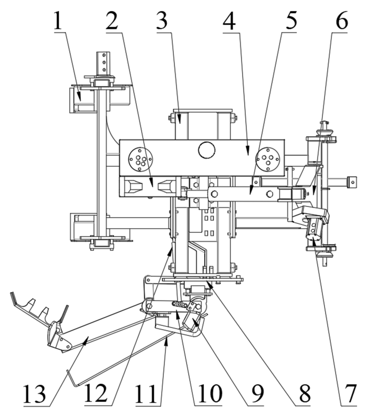
2.1.1. Structure of Weeding Machine

Figure 1 shows the overall structure of the intra-row obstacle avoidance shovel weeder. It mainly includes the wheels, machine frame, a three-point hitch, hydraulic system, and an intra-row weeding device. The wheels are installed at the rear of the machine frame to support the weeding equipment’s operation. The machine frame serves as the mounting carrier for the intra-row weeding components. The three-point hitch is mounted in front of the machine frame and is connected to the tractor’s suspension system. The hydraulic system mainly consists of a hydraulic oil tank, an air-cooled hydraulic radiator, solenoid valve, electromagnetic reversing valve, gear pump, and obstacle avoidance hydraulic cylinder. The tractor’s power take-off unit (PTO) is connected to the gear pump via the coupling to transfer power to the hydraulic system. The intra-row obstacle avoidance device consists of a weeding shovel, a sensor device, an obstacle avoidance hydraulic cylinder, a parallelogram mechanism, a connecting bracket, and an obstacle avoidance rod, designed specifically for intra-row weeding operations.

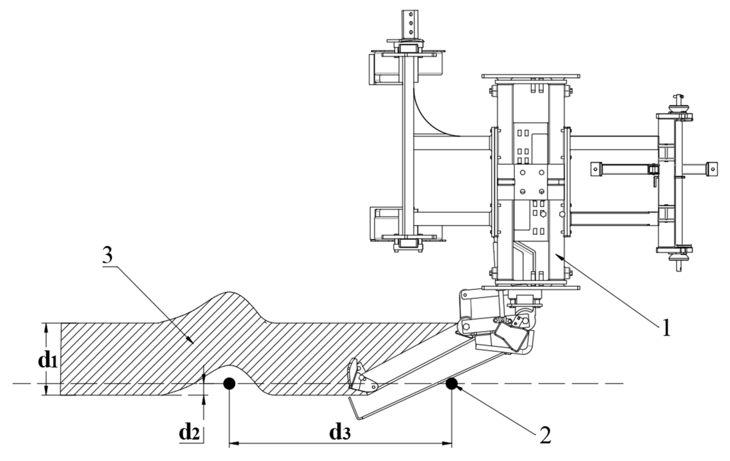
2.1.2. Working Principle of Weeding Machine

Before operating the intra-row avoidance shovel-type weeder, the tractor’s suspension is adjusted according to the work site to ensure that the wheels maintain effective contact with the ground. During operation, the tractor pulls the weeder using a three-point suspension system, transmitting power to the weeder’s hydraulic system via a coupling. The obstacle avoidance rod on the right side of the frame monitors grapevine obstacles in real time. When the rod does not touch an obstacle, hydraulic oil flows to the obstacle avoidance hydraulic cylinder through the electromagnetic reversing valve, causing the piston rod to extend. This action drives the parallelogram mechanism, moving the weeding shovel into the intra-row weeding position. When the obstacle avoidance rod touches a grapevine, it rotates around the rotary axis of the sensor device under pressure. Once the rotation reaches a certain angle and meets the control system’s threshold, a signal is generated. This signal triggers the electromagnetic reversing valve, causing the piston rod of the obstacle avoidance hydraulic cylinder to retract, which in turn drives the weeding shovel to circumvent the obstacle. When the obstacle avoidance rod leaves the grapevine, the reset spring returns it to its original position. At this time, the control system’s threshold is not reached, which triggers a control signal that acts on the electromagnetic reversing valve. This causes the piston rod of the obstacle avoidance hydraulic cylinder to extend, driving the weeding shovel back to the grapevine intra-row operation. The entire process is designed to avoid grapevines and perform shallow soil loosening and weeding operations between them.
The process of avoiding individual grapevines with an intra-row avoidance shovel-type weeder is shown in Figure 2, where the solid black circles represent the grapevines. Figure 2a represents the process of intra-row weeding operation before the weeding shovel avoids the grapevine. Figure 2b represents how, after the obstacle avoidance rod touches the grapevine and rotates, the sensor device transmits an electrical signal and the intra-row obstacle avoidance device prepares to start working. Figure 2c represents the intra-row avoidance operation being carried out by the weeding shovel. Figure 2d represents how, when the weeding shovel has finished avoiding the grapevine, it returns to carrying out intra-row weeding.

2.2. Key Component Design and Parameter Determination

2.2.1. Automatic Obstacle Avoidance Mechanism

As shown in Figure 3, solid black circles represent grapevines, the dotted line represents the grapevine row, and the area filled with diagonal lines indicates the area covered by the weeding shovel after it works. d1 represents the width of the weeding in the root zone of the grapevine. d2 represents the distance that the weeding shovel extends into the grapevine row. d3 represents the distance between two grapevines.
To enable the weeding shovel to avoid grapevines during operation, an automatic obstacle avoidance mechanism has been designed. It mainly consists of an obstacle avoidance hydraulic cylinder, a connecting bracket, a parallelogram mechanism, and a weeding shovel. During the operation, the piston rod of the obstacle avoidance hydraulic cylinder extends, causing the weeding shovel to rotate around hinge point G via the parallelogram mechanism, thus reaching intermediate areas of the grapevines for weeding. During obstacle avoidance, the piston rod of the obstacle avoidance hydraulic cylinder retracts under the hydraulic system’s action, driving the weeding shovel back into the grapevine rows via the parallelogram mechanism, thereby achieving obstacle avoidance.
To fulfill the requirements for intra-row weeding in grapevines, the coverage width (d1) of the weeding shovel is set at 350 mm. Simultaneously, to ensure effective penetration of the weeding shovel into intra-row grapevines during operation, d2 is set at 100 mm [26,27]. In the non-operating state of the intra-row weeding device, after the piston rod fully retracts, it is crucial to prevent collision with the side by ensuring the weeding shovel’s. Since the hydraulic cylinder’s expansion and contraction alter the weeding shovel’s position, it is necessary to conduct a kinematic analysis of the parallelogram mechanism, obstacle avoidance hydraulic cylinder, and weeding shovel within the intra-row weeding device. This involves determining structural parameters for the parallelogram mechanism and its shovel, as well as calculating dimensions for the obstacle avoidance hydraulic cylinder and its piston rod. Illustrated in Figure 4, the geometric relationship manifests when the obstacle avoidance hydraulic cylinder’s piston rod reaches maximum extension.
θ 5 = arcsin l 1 l 2 θ 6 = θ 5 + θ 4 π θ 7 = π 2 θ 6 θ 1 = arctan l 3 l 4 θ 2 = π θ 1 θ 7 l 5 = l 3 2 + l 4 2 l 7 = l 5 2 + l 6 2 2 l 5 l 6 cos θ 2
When the line containing line segment EF is parallel to the line containing line segment A2G, the parallelogram mechanism and its weeding shovel reach the critical retracted state (the state where the weeding shovel barely avoids colliding with side objects). This corresponds to position P1 in Figure 4, with the following geometric relationships.
l 10 2 = l 2 2 + l 8 2 2 l 2 l 8 cos θ 4 θ 8 = arccos l 10 2 + l 8 2 l 2 2 2 l 8 l 10 θ 3 = π 2 θ 8 θ 1 l 9 = l 5 2 + l 6 2 2 l 5 l 6 cos θ 3
As the obstacle avoidance hydraulic cylinder continuously retracts, a collision occurs when the line containing EK is parallel to the line containing MK, causing the parallelogram mechanism to collide with other components. Let α represent the angle between MK and FK at that moment. The subsequent calculation determines the minimum length dimension of the obstacle avoidance hydraulic cylinder block.
α = arctan l 3 l 4 l 11 L MCL 2 = l 5 2 + l 6 2 2 l 5 l 6 cos α θ 1
where l2, l3, l4, l6, l8, l11, and θ4 are the design dimensions and design angles of the parallelogram mechanism and its weeding shovel. l2 is 400 mm, l3 is 130 mm, l4 is 390 mm, l6 is 100 mm, l8 is 260 mm, l11 is 200 mm, and θ4 is 158°.
Following the calculation, the length of the obstacle avoidance hydraulic cylinder must exceed 317 mm to prevent collisions between parts. At maximum extension, the total length of the hydraulic cylinder and its piston rod, denoted as l7, is approximately 456 mm. When the parallelogram mechanism and its weeding shovel are in the critical retracted state, the combined length of the hydraulic cylinder and its piston rod, denoted as l9, is approximately 369 mm. Thus, the piston rod length is set at 87 mm and the body length of the obstacle avoidance hydraulic cylinder is set at 369 mm.

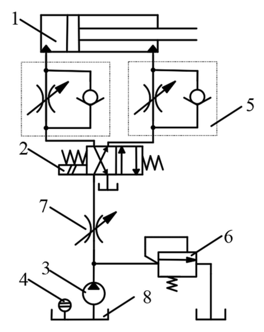
2.2.2. Obstacle Avoidance Hydraulic System

As shown in Figure 5, the hydraulic pump delivers a continuous flow of high-pressure fluid to the obstacle avoidance hydraulic system. To regulate system pressure and ensure safety, a relief valve is installed at the hydraulic pump outlet. The throttle valve adjusts the flow rate to control the extension speed of the obstacle avoidance hydraulic cylinder. Additionally, a one-way throttle valve is installed in each of the two connection lines between the obstacle avoidance hydraulic cylinder and the directional valve. This valve not only generates back pressure, reducing hydraulic shock and enhancing system stability and reliability, but also adjusts the retraction and extension speeds of the obstacle avoidance hydraulic cylinder. Upon detecting obstacles, the control system sends a signal to the electromagnetic reversing valve, prompting the internal valve body to shift left or right. This action alters the flow direction of the hydraulic fluid, enabling the piston rod of the obstacle avoidance hydraulic cylinder to extend and retract. Consequently, the weeding components maneuver to avoid obstacles.

2.2.3. Signal Acquisition Device

The signal acquisition device (Figure 6) comprises a sensor device, holding device, and obstacle avoidance rod, primarily utilized for identifying grapevines encountered during weeding operations. The obstacle avoidance rod consists of a long and a short straight section. One end of the long straight section is inserted into the holding device and secured below the sensor device’s rotating shaft with screws, allowing adjustment of the obstacle avoidance rod’s extension length using the holding device. Upon initial contact with a fruit tree, the obstacle avoidance rod is at position P3. Hindered by grapevines, it rotates around point M to position P4, triggering the sensor’s threshold. Subsequently, the controller sends a signal to the electromagnetic reversing valve, altering the obstacle avoidance hydraulic cylinder’s operation. This action drives the parallelogram mechanism and indirectly steers the weeding shovel to bypass the grapevine. Following successful evasion, the obstacle avoidance rod gradually returns to its initial position with assistance from the reset spring in the sensor device. This spring not only resets the obstacle avoidance rod but also ensures continuous contact between the rod and the grapevines throughout the evasion process.
To prevent a scenario where the obstacle avoidance rod does not make contact with the grapevines while the weeding shovel does during the weeding process, it is necessary to calculate the minimum length of the obstacle avoidance rod. Conclusions drawn from the triangular GAM depicted in Figure 4 and Figure 6 are as follows.
l 13 2 = l 10 2 + l 12 2 2 l 10 l 12 cos β 2 θ 8
where l12, β3, and β2 are the design size and design angle of the signal acquisition mechanism; l12 is 95 mm, β2 is 60°, and β3 is 148°.
Following the calculation, the length of the obstacle avoidance rod should slightly exceed l13. The initial selection for the length of the obstacle avoidance rod is 590 mm (determined from a weeding shovel length of 400 mm). In this design, the obstacle avoidance rod has a cross-sectional diameter of 8 mm, with a radius of the arc radius at 5 mm and arc length of 7.85 mm, and the short end measures 95 mm.

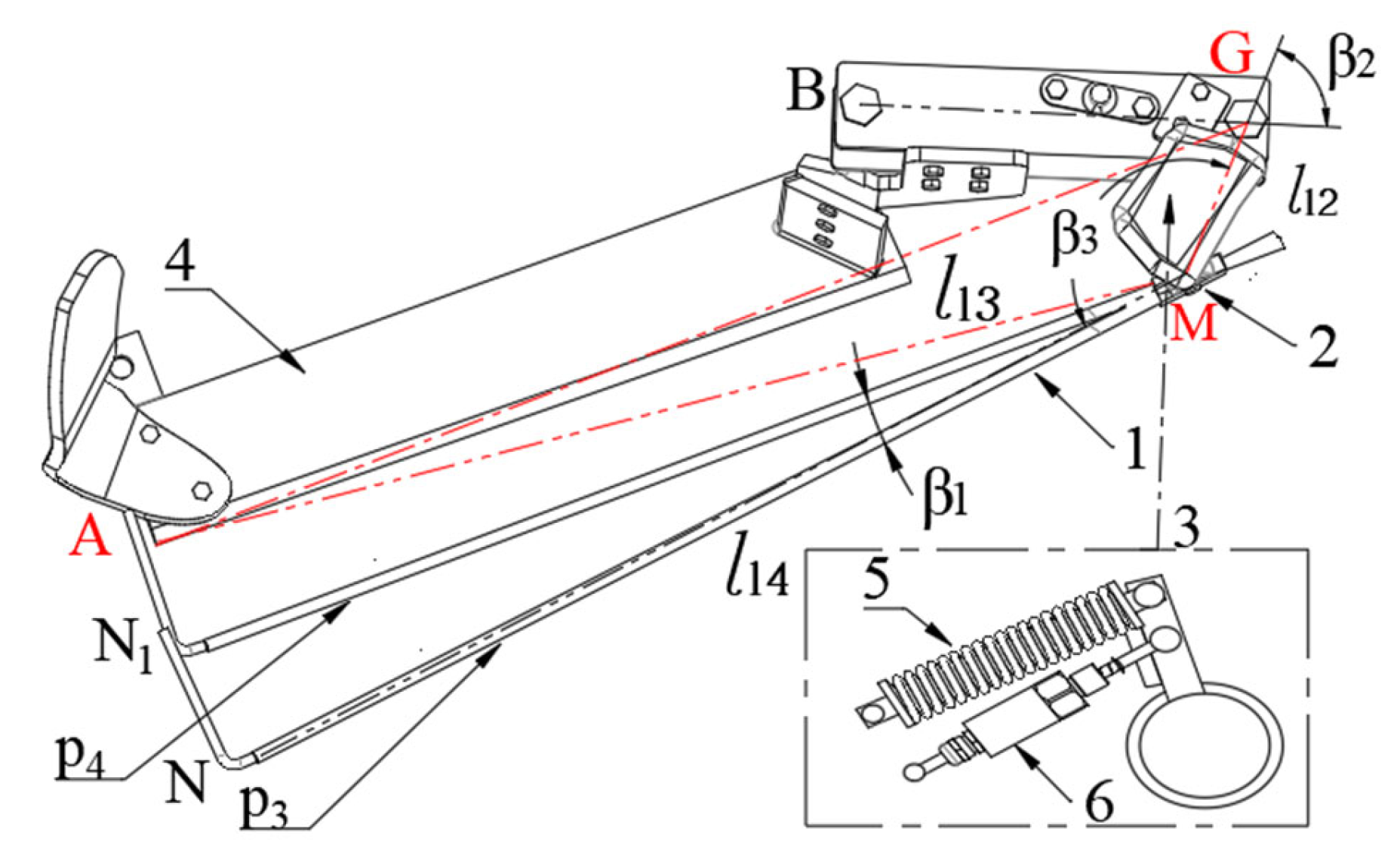
2.2.4. Determination of the Structural Parameters of the Weeding Shovel

During operation, the weeding shovel designed in this study is inserted slightly below the soil surface, reaching a soil depth of approximately 3 cm. It effectively removes weeds from the root. Compared to tools like ploughshares, the shovel-style weeding component minimizes soil disruption, thereby reducing its impact on soil stability [12]. The structural parameters of the weeding shovel are as follows: thickness of 12 mm, width of 85 mm, length of 400 mm, and cutting angle of 15°.

2.3. Analysis of the Extension and Retraction Speed of the Piston Rod of the Obstacle Avoidance Hydraulic Cylinder

2.3.1. Analysis of the Retraction Speed of the Piston Rod of the Obstacle Avoidance Hydraulic Cylinder

The retraction speed of the piston rod of the obstacle avoidance hydraulic cylinder is a crucial factor influencing the effect of intra-row weeding operations. During intra-row weeding, the obstacle avoidance hydraulic cylinder governs the rotation of the weeding shovel around the hinge point to avoid obstacles. If the retraction speed is too sluggish, despite grapevines detection by the signal acquisition mechanism, it could result in contact between the weeding shovel and the grapevines, potentially leading to damage or even destruction [28]. Conversely, excessive return speed of the hydraulic cylinder can result in significant impact of the piston rod on the hinge position of the parallelogram mechanism during retraction. Hence, it is crucial to establish an appropriate retraction speed for the obstacle avoidance hydraulic cylinder.
During intra-row weeding operations, the obstacle avoidance rod initially makes contact with the grapevine and subsequently rotates around the rotation axis of the sensor device. Upon reaching a certain angle threshold, the obstacle avoidance hydraulic cylinder initiates an operation to steer the weeding shovel clear of the grapevine. A mathematical model must be developed for this scenario to determine an appropriate retraction speed for the piston rod of the obstacle avoidance hydraulic cylinder. Initially, it is crucial to ascertain the relative horizontal distance (l16) between the weeding shovel and the grapevine when the weeding shovel begins to evade obstacles. The formula derivation is outlined below based on Figure 4, Figure 6 and Figure 7.
β 4 = 2 π θ 1 θ 2 + β 1 β 2 β 3 G P = l 12 sin β 3 β 1   /   sin β 4 G J = l 10 cos ( π θ 1 θ 2 θ 8 ) A 1 J = l 10 sin ( π θ 1 θ 2 θ 8 ) l 15 = G J G P d 2 O 1 Q = l 15 tan β 4 l 16 = A 1 J O 1 Q
When the piston rod of the hydraulic cylinder is at its maximum extension and it retracts at a uniform speed, v1, the angle φ1 changes over time. The equation for the derivation of φ1 is as follows.
φ 1 = arccos l 5 2 + l 6 2 l 7 ν 1 t 2 2 l 5 l 6
When the weeding machine is traveling at speed v2 and the piston rod of the obstacle avoidance hydraulic cylinder is retracting at v1, the displacement equation of point A1 in the right-angled coordinate system is as follows (set point A1 at the origin of the right-angled coordinate system, then the grapevine is located at (l16,d2)).
y ( t ) = l 10 sin φ 1 + θ 1 + θ 8 + π 2 l 10 sin arccos l 5 2 + l 6 2 l 7 2 2 l 5 l 6 + θ 1 + θ 8 + π 2 x ( t ) = l 10 cos φ 1 + θ 1 + θ 8 + π 2 l 10 cos arccos l 5 2 + l 6 2 l 7 2 2 l 5 l 6 + θ 1 + θ 8 + π 2 + ν 2 t
Using MATLAB (Version 2020, The MathWorks, Inc., Natick, MA, USA), the motion trajectory was plotted and analyzed based on the known displacement function and grapevine coordinates. Figure 8 illustrates that the designated safe distance between the weeding shovel and the grapevine (5 cm) forms a circular area. By maintaining fixed parameters such as the length of the weeding shovel, the forward speed of the weeding machine, and angle threshold (the angle of rotation of the obstacle avoidance rod that triggering the contraction of the obstacle avoidance hydraulic cylinder), the retraction speed is adjusted to align the motion trajectory approximately tangent to the circular area. At this juncture, the retraction speed represents the critical retraction speed (defined as the minimum retraction speed of the piston rod when the weeding shovel avoids the grapevines).
Further investigation into the impact of retraction speed during the obstacle avoidance process on the area of weeding omissions (un-cleared areas after the weeding operation) requires additional analysis. The obstacle avoidance process is simulated using ADAMS software (Version 2020) to generate the dynamic trajectory of the weeding shovel’s end (specific simulation steps are detailed in Section 2.4). The simulation trajectory diagram (as shown in Figure 9) illustrates the movement trajectory of the weeding shovel and its corresponding weeding effect. This facilitates a more intuitive observation and comprehension of how retraction speed influences the weeding effectiveness of the weeding machine during obstacle avoidance through visualized data. From the Figure 9a–d, it is evident that, while keeping other parameters constant, as the retraction speed gradually surpasses the critical retraction speed the area of weeding omissions steadily enlarges (the area in the middle of the graph from each trajectory line to Y = 0 is the area of weeding omission). This observation highlights that employing the critical retraction speed for the obstacle avoidance hydraulic cylinder not only prevents contact between the weeding shovel and the grapevine but also minimizes the area of weeding omissions to the greatest extent. Hence, in the subsequent analysis of this paper, the retraction speed of the obstacle avoidance hydraulic cylinder will be set to the critical retraction speed.

2.3.2. Analysis of the Extension Speed of the Piston Rod of the Obstacle Avoidance Hydraulic Cylinder

The extension speed of the obstacle avoidance hydraulic cylinder is another critical factor influencing the weeding effectiveness between plants. Following the evasion of the grapevine by the weeding shovel, the insufficient extension speed of the obstacle avoidance hydraulic cylinder may cause delayed penetration of the weeding shovel into the grapevines interval, resulting in an extensive area of weeding omission. Thus, analyzing the movement of the weeding shovel as it re-enters the intra-row of the grapevine is essential to determine the suitable extension speed for the obstacle avoidance hydraulic cylinder.
Figure 10 shows the moment when the weeding shovel is about to complete obstacle avoidance. It is used to analyze the area of missed weeding from obstacle avoidance completion to resuming work. The solid black circles represent grapevines. The distance between the two red dotted lines is d2, representing the distance the weeding spade reaches into the row of grapevines, and d3 represents the vertical distance from the end of the weeding spade at the beginning of the avoidance to the end of the weeding spade at the end of the avoidance.
To ascertain the area of weeding omissions from the completion of the weeding shovel’s obstacle avoidance to its re-entry into the intra-row operation process, it is crucial to establish the reference value d3. Previous analysis indicates that d3 varies within a narrow range of 150 mm, hence it is uniformly set at 150 mm. As the obstacle avoidance of the weeding shovel nears completion, the combined length of the obstacle avoidance hydraulic cylinder and its piston rod (estimated value) at this juncture can be calculated using geometric relationships.
l 17 = l 5 2 + l 6 2 2 l 5 l 6 cos π θ 1 θ 8 arccos G J d 3 l 10
After the obstacle avoidance concludes, the piston rod of the obstacle avoidance hydraulic cylinder drives the intra-row obstacle avoidance device to re-enter the intra-row at a speed of v3. The angle φ2 varies with time, as deduced from the cosine formula presented below.
φ 2 = arccos l 5 2 + l 6 2 l 17 + ν 3 t 2 2 l 5 l 6
Assuming the weeding machine travels at a speed of v2 and the piston rod of the obstacle avoidance hydraulic cylinder extends at a speed of v3, the displacement formula of the weeding shovel’s endpoint in the Cartesian coordinate system is expressed as follows (assuming point A2 is positioned at (0, d3) in the Cartesian coordinate system). Integrating the displacement function allows obtaining the area of weeding omission, denoted as S1 (representing the area of weeding omission when the weeding shovel re-enters the grapevine row after completing obstacle avoidance). The omission rate Q is calculated by dividing S1 by the total area S.
y ( t ) = l 10 sin φ 2 + θ 1 + θ 8 + π 2 l 10 sin arccos l 5 2 + l 6 2 l 17 2 2 l 5 l 6 + θ 1 + θ 8 + π 2 + d 3 x ( t ) = l 10 cos φ 2 + θ 1 + θ 8 + π 2 l 10 cos arccos l 5 2 + l 6 2 l 17 2 2 l 5 l 6 + θ 1 + θ 8 + π 2 + ν 2 t
t = l 7 l 17 v 3 S = d 1 × d 3 S 1 = 0 t y ( t ) x ( t ) d t Q = S 1 S × 100 %
Note: S1 represents the area of weeding omission when the weeding shovel finishes obstacle avoidance and re-enters the intra-row space for weeding operations, mm2; S is the set total work area that should be weeded, mm2; d1 is the width of the weeding shovel covering area, (mm); d3 is the plant spacing, (mm); t is the time required for the weeding shovel to avoid the obstacle and then re-reach into the intra-row of grapevine operation.
Analysis of the weeding omission rate under various parameters using MATLAB’s mathematical model reveals, as depicted in Figure 11, that with constant forward and extension speeds, altering the length of the weeding shovel has minimal impact on the weeding omission rate. Conversely, maintaining the weeding shovel’s length and extension speed at constant, increasing the machine’s forward speed results in an increase in the weeding omission rate. Keeping the length of the weeding shovel and forward speed constant, augmenting the extension speed of the obstacle avoidance hydraulic cylinder decreases the weeding omission rate. Insufficient extension speed can result in a disproportionately large area of weeding omission, thereby impacting the weeding effectiveness. However, excessively fast extension speed is not optimal either. With increasing obstacle avoidance hydraulic cylinder outstretching speed, the reduction in weeding omission rate becomes less pronounced. As the obstacle avoidance hydraulic cylinder extension speed increases, the instantaneous stress at the hinge points of the intra-row weeding mechanism also rises, potentially affecting the device’s stability and lifespan. Preliminary analyses selected a weeding shovel length of 400 mm and a forward speed of 1.0 m/s as benchmarks. Obstacle avoidance hydraulic cylinder extension speed starting from 100 mm/s and increasing by 10 mm/s increments, the change rate of weeding omission is less than 0.5%, with diminishing change amplitude. Therefore, the final selected range for obstacle avoidance hydraulic cylinder extension speed is 80–120 mm/s.

2.4. Simulation Analysis of Weeding Shovel Motion Trajectory

Establishment of Simulation Model

The area encompassed by the trajectory of the weeding shovel significantly influences the weeding efficacy during the intra-row obstacle avoidance weeder’s operation. Upon initial examination, this trajectory is influenced by multiple factors, such as the extension and retraction speeds of the piston rod of the obstacle avoidance hydraulic cylinder, the forward speed of the weeding machine, the angular threshold (representing the angle of rotation of the obstacle avoidance rod that initiates the contraction of the obstacle avoidance hydraulic cylinder), the elasticity coefficient of the reset spring, and the length of the weeding shovel. To comprehensively explore the impact of these structural and motion parameters on the weeding efficacy, this study developed a virtual simulation model of the weeding machine using ADAMS software (Version 2020). It then conducted virtual simulation single-factor experiments and a quadratic regression combination experiment, with the objective of offering insights into the selection of experimental parameters and the optimization of the prototype machine.
The primary objective of the simulation experiment is to replicate the motion trajectory of the weeding shovel during weeding operations and to assess the influence of the structure and its motion parameters on the weeding coverage area. The simulation model was generated in Solidworks (Version 2020, Dassault Systèmes Company, Waltham, MA, USA) software and then imported into ADAMS in .stp format [29,30]. The model primarily consists of the connecting bracket, sensor device, parallelogram mechanism, obstacle avoidance hydraulic cylinder, obstacle avoidance rod, weeding shovel, and grapevine, among other components. In this context, the grapevine is represented as a cylindrical body with a diameter of 40 mm, and it is assigned a wooden material. The other components are made of steel. Considering the motion patterns of different parts during actual operation, constraints such as fixed joints, rotating joints, cylindrical joints, and sliding joints are implemented between the components. Additionally, to replicate the collision dynamics between the obstacle avoidance rod and grapevines, a contact force is applied between them [31]. Moreover, to facilitate the obstacle avoidance rod’s return to its initial position post-avoidance, a spring force is incorporated between the obstacle avoidance rod and the machine frame. Furthermore, two translational drives are incorporated into the mobile components to mimic the forward movement of the tractor and the expansion and contraction motion of the hydraulic cylinder. The IF function in ADAMS was employed to define the operating speed of the obstacle avoidance hydraulic cylinder piston rod.
ν = IF ( δ β 1 : ν 2 : ν 1 : ν 1 )
Note: v is the speed of the piston rod of the obstacle avoidance hydraulic cylinder during operation, mm/s; v1 is the retraction speed of the piston rod of the obstacle avoidance hydraulic cylinder, mm/s; v2 is the extension speed of the piston rod of the obstacle avoidance hydraulic cylinder, mm/s; β1 is the angle of rotation around the M-point during the movement of the contact rod (angular threshold) (°); δ is the angle of the ∠AMN of Figure 6 (°).
The entire simulation process is automated through a script. As the translational drive operates, the connecting bracket consistently propels the other components forward. Upon the sensor detecting that the obstacle avoidance rod has reached a predetermined angle threshold, it disengages the fixed joint of the weeding shovel and engages the translational drive of the obstacle avoidance hydraulic cylinder, thereby initiating the obstacle avoidance maneuver. Following obstacle avoidance, when the sensor registers that the Y-coordinate of the weeding shovel’s end matches the Y-coordinate of its starting position, it re-engages the fixed joint of the weeding shovel while disengaging the translational drive of the obstacle avoidance hydraulic cylinder. Subsequently, upon completing the simulation, marker points are positioned at each end of the weeding shovel, and the point trace line function is utilized to track the working trajectory of the weeding shovel (as shown in Figure 12).

3. Results

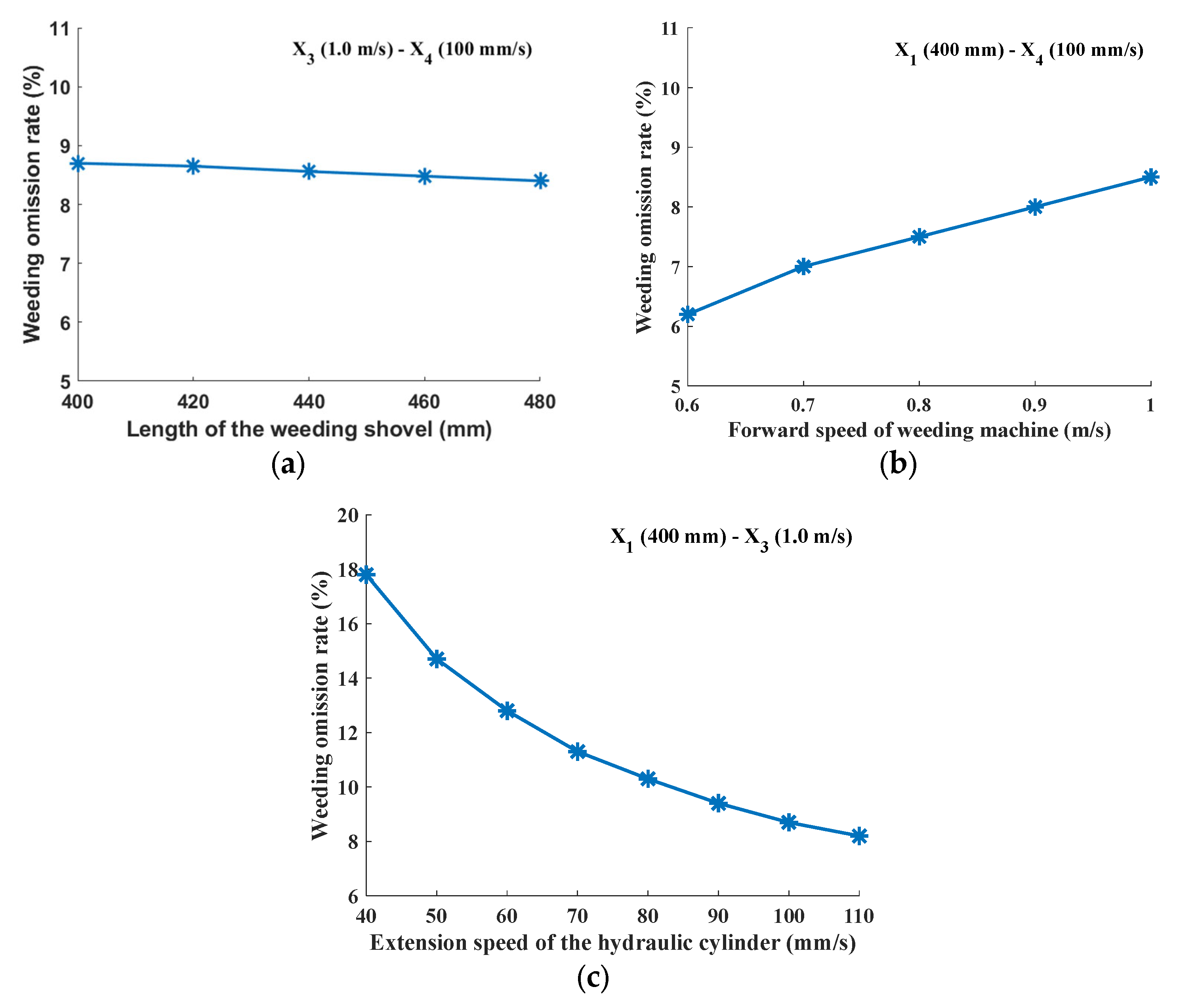
3.1. Single Factor Simulation Experiment

The effectiveness of weed control operations depends directly on the coverage rate of the weeding operation. Single-factor simulation experiments aim to identify the key factors that affect the coverage rate of the weeding operation, laying the groundwork for subsequent trials.
The simulation test focuses on five factors: the extension speed of the piston rod of the obstacle avoidance hydraulic cylinder, the forward speed of the weeding machine, the angle threshold, the reset spring elasticity coefficient, and the length of the weeding shovel (following preliminary simulation results, the critical retraction speed is applied in subsequent simulation experiments). The extension speed of the piston rod of the obstacle avoidance hydraulic cylinder ranges from 80 to 120 mm/s, the forward speed of the weeding machine ranges from 0.6 to 1 m/s, the angle threshold varies from 14 to 18°, the reset spring elasticity coefficient ranges from 10 to 30 N/mm, and the length of the weeding shovel varies from 400 to 480 mm. To analyze the impact of each factor on the weeding effectiveness, each research variable is examined across five levels, employing the coverage rate of the weeding operation as the evaluation criterion. The control variable method is applied, and each of the five research variables undergoes single-factor analysis. This entails setting the remaining four variables at intermediate level values while analyzing one variable at a time. Sequential simulation results for all five variables are obtained using this approach, as depicted in Figure 13.
M = S S 2 S × 100 % S = d 1 × d 3
Note: M is the coverage rate of weeding operation, %; S is the set total work area that should be weeded, mm2; S2 represents the area of weeding omission from the start of obstacle avoidance by the weeding shovel until it re-enters the intra-row space for weeding operations, mm2; d1 is the width of the weeding shovel covering area (350), mm; d3 is the plant spacing (1000), mm.
Analysis of Figure 13 reveals that, within the chosen level range, as the forward speed of the weeding machine rises, the coverage rate of the weeding operation gradually diminishes, indicating a negative correlation trend with a substantial degree of change. Conversely, an increase in the extension speed of the piston rod correlates with a gradual rise in the coverage rate of the weeding operation, demonstrating a positive correlation trend with a notable degree of change. Additionally, as the angular threshold increases, the coverage rate of the weeding operation gradually ascends, indicating a positive correlation trend, albeit with an insignificant degree of change. As the reset spring elasticity coefficient and the length of the weeding shovel increase, there is no clear trend observed in the change of the coverage rate of the weeding operation, and the degree of change is not significant. Consequently, it is established that the extension speed of the piston rod and the forward speed of the weeding machine are the primary factors influencing the effectiveness of the weeding operation, with the angle threshold serving as a secondary factor. In contrast, the reset spring elasticity coefficient and the length of the weeding shovel are deemed irrelevant factors.

3.2. Quadratic Regression Combination Experiment

3.2.1. Test Results and Analysis

To determine the optimal parameters for the coverage rate of the weeding operation, further analyses are warranted. Design-Expert (Version 10, Stat-Ease, Inc., Minneapolis, MN, USA) software is utilized to construct a coded table of test factor levels based on Box–Behnken design principles and to conduct a quadratic regression combination experiment, as illustrated in Table 1 and Table 2. Based on the preceding simulation test results and analyses, the test factors include piston rod extension speed, forward speed of the weeding machine, and angle threshold. Employing Design-Expert to fit the experimental data presented in Table 2 and perform an analysis of variance, the 2FI model is employed to establish the regression model for the coverage rate of weeding operations. According to the ANOVA results, the coefficients of Z1, Z2, Z3, and Z1Z2 are significant (p < 0.05), while the remaining coefficients are not significant. The Adj R-Squared is 0.9864, indicating that the model fits the data very well. The Pred R-Squared is 0.9691, which is close to the Adj R-Squared, suggesting that the model has good predictive ability for new data. By removing the insignificant items, the regression equation for the coverage rate of weeding operations is obtained: M = 82.76 + 1.64Z1 − 2.05Z2 + 0.79Z3 + 0.43Z1Z2. The Design-Expert optimization module was used to determine the optimal solution for the three factors by solving the regression model. The constraints for the experimental factors are as follows: piston rod extension speed of 80–120 mm/s, forward speed of 0.6–1 m/s, and angle threshold of 14–18°. The target maximum value for the coverage rate of the weeding operation, as the evaluation index, is 100%. The final optimized parameters are as follows: piston rod extension speed of 120 mm/s, weeding machine forward speed of 0.6 m/s, and angle threshold of 18°. Additional parameters are as follows: weeding shovel length of 400 mm, critical retraction speed of 65 mm/s, and reset spring elastic coefficient of 20 N/mm. The optimal coverage rate of the weeding operation under these conditions is 86.8%.

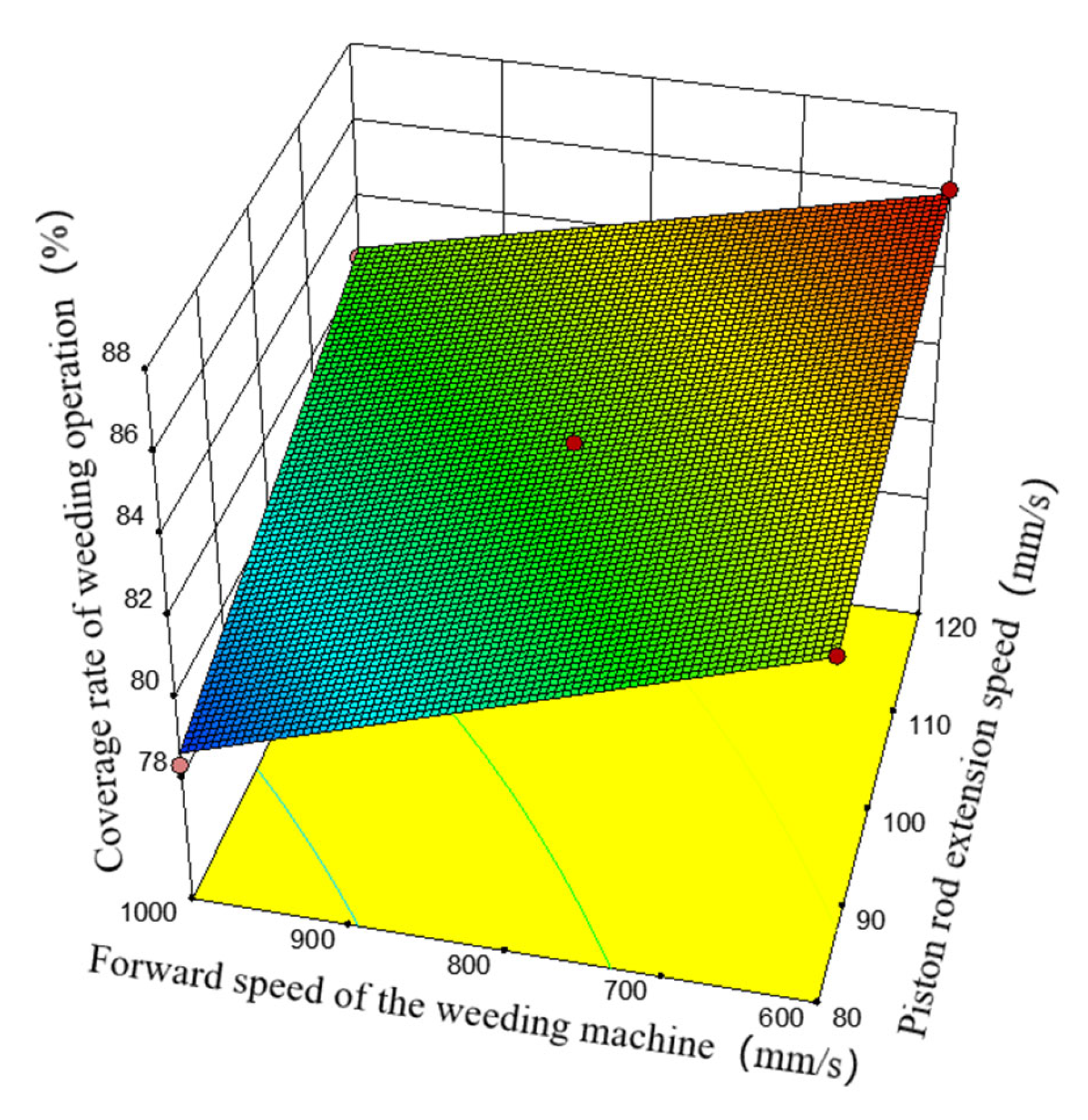
3.2.2. Response Surface Analysis

The Design-Expert analysis revealed an interaction between the obstacle avoidance hydraulic cylinder extension speed and the weeding machine’s forward speed (Z1Z2). The response surface plot was used to analyze how this interaction affects the coverage rate of the weeding operation.
Figure 14 shows that as the obstacle avoidance hydraulic cylinder extension speed increases, the coverage rate of the weeding operation also increases. This is mainly because the return speed of the obstacle avoidance hydraulic cylinder is set to the critical return speed, which leads to the similar weeding missing area caused by the obstacle avoidance process under different parameters. The changes affecting the coverage rate occur primarily between the weeding shovel’s completion of avoidance and its re-entry into intra-plant operation. The main factors affecting this process are implement speed and obstacle avoidance hydraulic cylinder extension speed. With a constant forward speed, a higher obstacle avoidance hydraulic cylinder extension speed reduces the time needed for the weeding shovel to avoid obstacles and resume operation. This reduction in area of weeding omission increases the coverage rate of weeding operations. As the forward speed of the weeding machine increases, the coverage rate of the weeding operation decreases. When the obstacle avoidance hydraulic cylinder extension speed is constant, a higher forward speed means that although the time for the weeding shovel to avoid obstacles and resume operation remains unchanged, the sliding distance at the end of the weeding shovel increases. Consequently, the area of weeding omission increases, reducing the coverage rate of the weeding operation.

3.3. Simulation Analysis at Different Plant Spacings

The above analysis pertains to vineyards with a grapevine spacing of 1 m. Variations in grapevine spacing may affect the weeding operation coverage rate, necessitating further research on this impact. Using the structural and operating parameters for the optimal weeding operation coverage rate, grapevine spacing is set to 600–1000 mm. The impact of this spacing on the coverage rate is analyzed through single-factor simulation. As shown in Figure 15, the weeding operation coverage rate significantly drops as grapevine spacing decreases. Analysis shows that the missed area during weeding mainly exists on the opposite side of the operating row. As grapevine spacing decreases, the missed weeding area remains almost the same, but the operation area (grapevine spacing × width) decreases, leading to a reduction in the weeding operation coverage rate. Preliminary analysis indicates that when the weeding machine operates on one side of the crop row, the weeding effect becomes less ideal as the grapevine spacing decreases. The weeding effect will be further enhanced if the weeding machine operates on both sides of the grape row.

4. Discussion

Simulation analysis reveals that the primary factors influencing the coverage rate of weeding operations are the forward speed of the weeding machine and the extension speed of the piston rod. Although the coverage rate of weeding operations exhibits a trend of increasing or decreasing with the length of the weeding shovel, angle threshold, and spring coefficient, the changes are not significant. This finding contrasts somewhat with other similar studies, which suggest that the angle threshold or elasticity coefficient has a significant impact on the coverage rate of weeding operations [26]. In previous studies, the retraction speed of the piston rod was set equal to the extension speed and considered a variable. In this paper, the extension speed and retraction speed are investigated independently, and the obstacle avoidance hydraulic cylinder retraction speed is determined using the critical retraction speed. The critical retraction speed is dependent on the forward speed of the weeding machine, angle threshold, and structural parameters. Preliminary analysis indicates that utilizing the critical retraction speed may mitigate the impact of changes in the angle threshold and spring coefficient on the coverage rate of weeding operations.
The combination of a shovel-type weeder and a finger-type weeder yields superior weeding results compared to using a single weeder [14,32]. However, by optimizing various parameters in this study, the coverage rate of weeding operations has been significantly enhanced, achieving results comparable to those of combined operations. This optimization reduces the number of required tools, thereby saving costs and time. It should be noted that this study has some limitations. The simulation tests have attempted to model operations in a real-world environment as closely as possible. However, in actual vineyard operations, narrow vine spacing in certain areas may hinder the weeding mechanism from entering the intra-row space before needing to perform obstacle avoidance again, resulting in larger areas of weeding omission. Additionally, unlike the instantaneous sensor responses in simulations, sensors in real operations may experience significant delays, potentially causing situations where the weeding components do not retract in time, leading to collisions with the grapevines. Therefore, future studies should focus on validating the performance of the weeder in field operations. Moreover, to improve the effectiveness and efficiency of the vineyard’s intra-row obstacle avoidance shovel weeder, new technologies and devices, such as depth adjustment mechanisms and bilateral weeding devices, should be integrated. Additionally, technologies like automatic navigation, image recognition, and multi-sensor fusion could be incorporated into weeders to enable unmanned operation modes [33,34,35,36,37,38].

5. Conclusions

This paper presents the design of an intra-row obstacle avoidance shovel-type weeding machine. The theoretical analysis of intra-row weeding components guided the determination of key part structures and parameters, including the signal acquisition mechanism, automatic obstacle avoidance mechanism, and weeding blade. Furthermore, a hydraulic system was developed. By leveraging intra-row weeding operations and labor cost savings, this design aims to enhance weed control effectiveness and prevent collisions between weeding equipment and grapevines.
Through establishing a kinematic model, we determined the minimum retraction speed of the obstacle avoidance hydraulic cylinder. This speed aims to prevent the weeding shovel from contacting grapevines and minimize the area of weeding omission. It was found that inadequate extension speed of the obstacle avoidance hydraulic cylinder increases the area of weeding omission. The optimal extension speed range of the obstacle avoidance hydraulic cylinder was determined to be 80–120 mm/s. Using ADAMS analysis, we conducted a one-factor simulation test with the coverage rate of weeding operations as the evaluation index. It was found that the obstacle avoidance hydraulic cylinder extension speed and the forward speed of the weeding machine were the primary influencing factors, while the angular threshold played a secondary role. Utilizing a quadratic regression combination experiment design, a three-factor, three-level response surface analysis was performed to establish a regression model for the coverage rate of weeding operations. The results indicated that the optimal parameters were an obstacle avoidance hydraulic cylinder extension speed of 120 mm/s, a forward speed of 0.6 m/s, and an angular threshold of 18°, achieving a coverage rate of weeding operations of 86.8%.

Author Contributions

Conceptualization, W.J. and K.T.; data curation, K.T.; formal analysis, W.J. and X.D.; funding acquisition, W.J. and M.O.; investigation, K.T.; methodology, K.T. and X.W.; project administration, W.J.; resources, W.J.; software, X.W.; supervision, W.J. and M.O.; validation, X.D. and M.O.; visualization, X.W. and X.D.; writing—original draft, W.J., K.T. and X.W.; writing—review and editing, W.J., K.T. and X.W. All authors have read and agreed to the published version of the manuscript.

Funding

This research was funded by the National Key Research and Development Plan of China (Ministry of Science and Technology of the People’s Republic of China, Grant No. 2023YFD2000503), Jiangsu Province and Education Ministry Cosponsored Synergistic Innovation Center of Modern Agricultural Equipment (Jiangsu University, Grant No. XTCX1003), the Jiangsu University and Wuzhong City Campus Cooperation Project (Wuzhong Science and Technology Bureau, Grant No. zk20230012), a Project Funded by the Priority Academic Program Development of Jiangsu Higher Education Institutions (Jiangsu Education Department, Grant No. PAPD-2023-87) and the Open Fund for Key Laboratory of Modern Agricultural Equipment and Technology (Jiangsu University, Grant No. MAET202113).

Institutional Review Board Statement

Not applicable.

Data Availability Statement

The data presented in this study are available on request from the corresponding author.

Conflicts of Interest

The authors declare no conflicts of interest.

References

  1. Souza, E.; Leal, I.; Umsza-Guez, M.; Machado, B. Evaluation of the Technological Potential of Grape Peels through Patent Document Analysis: Agro-industrial Waste with Biotechnological Potential. Recent. Pat. Nanotechnol. 2021, 15, 35–346. [Google Scholar] [CrossRef] [PubMed]
  2. Cabrera-Pérez, C.; Valencia-Gredilla, F.; Royo-Esnal, A.; Recasens, J. Organic Mulches as an Alternative to Conventional Under-Vine Weed Management in Mediterranean Irrigated Vineyards. Plants 2022, 11, 2785. [Google Scholar] [CrossRef] [PubMed]
  3. Andert, S. The Method and Timing of Weed Control Affect the Productivity of Intercropped Maize (Zea mays L.) and Bean (Phaseolus vulgaris L.). Agriculture 2021, 11, 380. [Google Scholar] [CrossRef]
  4. Morin, L. Progress in Biological Control of Weeds with Plant Pathogens. Annu. Rev. Phytopathol. 2020, 58, 201–213. [Google Scholar] [CrossRef]
  5. Monteiro, A.; Santos, S. Sustainable Approach to Weed Management: The Role of Precision Weed Management. Agronomy 2022, 12, 118. [Google Scholar] [CrossRef]
  6. Guo, Y.; Cheng, L.; Long, W.; Gao, J.; Zhang, J.F.; Chen, S.; Pu, H.M.; Hu, M.L. Synergistic mutations of two rapeseed AHAS genes confer high resistance to sulfonylurea herbicides for weed control. Theor. Appl. Genet. 2020, 133, 2811–2824. [Google Scholar] [CrossRef]
  7. Li, H.; Travlos, I.; Qi, L.; Kanatas, P.; Wang, P. Optimization of Herbicide Use: Study on Spreading and Evaporation Characteristics of Glyphosate-Organic Silicone Mixture Droplets on Weed Leaves. Agronomy 2019, 9, 547. [Google Scholar] [CrossRef]
  8. Winston, R.; Schwarzländer, M.; Hinz, H.; Pratt, P. Prioritizing Weeds for Biological Control Development in the Western USA: Adaptation of the Biological Control Target Selection System. Biocontrol 2024, 69, 335–351. [Google Scholar] [CrossRef]
  9. Zhu, H.; Zhang, Y.; Mu, D.; Bai, L.; Zhuang, H.; Li, H. YOLOX-based Blue Laser Weeding Robot in Corn Field. Front. Plant. Sci. 2022, 13, 1017803. [Google Scholar] [CrossRef]
  10. Michaliszyn-Gabrys, B.; Bronder, J.; Jarosz, W.; Krupanek, J. Potential of Eco-Weeding with High-Power Laser Adoption from the Farmers’ Perspective. Sustainability 2024, 16, 2353. [Google Scholar] [CrossRef]
  11. Sportelli, M.; Frasconi, C.; Fontanelli, M.; Pirchio, M.; Raffaelli, M.; Magni, S.; Caturegli, L.; Volterrani, M.; Mainardi, M.; Peruzzi, A. Autonomous Mowing and Complete Floor Cover for Weed Control in Vineyards. Agronomy 2021, 11, 538. [Google Scholar] [CrossRef]
  12. Gagliardi, L.; Fontanelli, M.; Luglio, S.; Frasconi, C.; Peruzzi, A.; Raffaelli, M. Evaluation of Sustainable Strategies for Mechanical Under-Row Weed Control in the Vineyard. Agronomy 2023, 13, 3005. [Google Scholar] [CrossRef]
  13. Gagliardi, L.; Luglio, S.; Peruzzi, A.; Fontanelli, M.; Frasconi, C.; Raffaelli, M. Comparative Analysis of the Performance of a Chain Mower and Tools That Perform Under-Row Weed Control with Tillage in the Vineyard. Agronomy 2024, 14, 206. [Google Scholar] [CrossRef]
  14. Pergher, G.; Gubiani, R.; Mainardis, M. Field Testing of a Biomass-Fueled Flamer for In-Row Weed Control in the Vineyard. Agriculture 2019, 9, 210. [Google Scholar] [CrossRef]
  15. Mwitta, C.; Rains, G.; Prostko, E. Evaluation of Diode Laser Treatments to Manage Weeds in Row Crops. Agronomy 2022, 12, 2681. [Google Scholar] [CrossRef]
  16. Zawada, M.; Legutko, S.; Goscianska-Lowinska, J.; Szymczyk, S.; Nijak, M.; Wojciechowski, J. Mechanical Weed Control Systems: Methods and Effectiveness. Sustainability 2023, 15, 15206. [Google Scholar] [CrossRef]
  17. Parasca, S.; Spaeth, M.; Rusu, T.; Bogdan, I. Mechanical Weed Control: Sensor-based Inter-row Hoeing in Sugar Beet (Beta vulgaris L.) in the Transylvanian Depression. Agronomy 2024, 14, 176. [Google Scholar] [CrossRef]
  18. Liu, C.; Yang, K.; Chen, Y.; Gong, H.; Feng, X.; Tang, Z. Benefits of Mechanical Weeding for Weed Control, Rice Growth Characteristics and Yield in Paddy Fields. Field Crops Res. 2023, 293, 108852. [Google Scholar] [CrossRef]
  19. Sampurno, R.; Liu, Z.; Abeyrathna, R.; Ahamed, T. Intrarow Uncut Weed Detection Using You-Only-Look-Once Instance Segmentation for Orchard Plantations. Sensors 2024, 24, 893. [Google Scholar] [CrossRef]
  20. Tillett, N.; Hague, T.; Grundy, A.; Dedousis, A. Mechanical within-row Weed Control for Transplanted Crops Using Computer Vision. Biosyst. Eng. 2008, 99, 171–178. [Google Scholar] [CrossRef]
  21. Gobor, Z.; Lammers, P.; Martinov, M. Development of a Mechatronic Intra-row Weeding System with Rotational Hoeing Tools: Theoretical Approach and Simulation. Comput. Electron. Agric. 2013, 98, 166–174. [Google Scholar] [CrossRef]
  22. Pérez-Ruiz, M.; Slaughter, D.; Gliever, C.; Upadhyaya, S.K. Automatic GPS-based Intra-row Weed Knife Control System for Transplanted Row Crops. Comput. Electron. Agric. 2012, 80, 41–49. [Google Scholar] [CrossRef]
  23. Xu, L.; Yu, C.; Liu, W.; Yuan, Q.; Ma, S.; Duan, Z.; Xing, J. Optimal Design on Auto Obstacle Avoidance Mechanism of Intra-row Weeder for Trellis Cultivated Grape. Trans. Chin. Soc. Agric. Eng. 2018, 34, 23–30. [Google Scholar] [CrossRef]
  24. Lin, J.; Wang, D.; Lv, Z.; Wang, X. Design and Experimental Study on Intelligent Obstacle Avoidance System for Orchard Rototiller. J. Shenyang. Agric. Univ. 2023, 54, 165–175. [Google Scholar] [CrossRef]
  25. Shen, Q.; Lei, X.; Ma, Z.; Li, J. Experimental Study on F.US UFO Mower for Avoiding Obstacles in Orchards. J. Chin. Agric. Mech. 2021, 42, 65–77. [Google Scholar] [CrossRef]
  26. Wang, Y.; Kang, J.; Peng, Q.; Chen, Y.; Fang, H.; Niu, M.; Wang, S. Design and Experiment of Obstacle Avoidance Weeding Machine for Fruit Trees. J. Jilin Univ. Eng. Technol. Ed. 2023, 53, 2410–2420. [Google Scholar] [CrossRef]
  27. Yu, C.; Xu, L.; Wang, Q.; Yuan, Q.; Ma, S.; Niu, C.; Yuan, X.; Zeng, J.; Wang, S.; Chen, C. Design and Experiment of Bilateral Operation Intra-row Auto Obstacle Avoidance Weeder for Trellis Cultivated Grape. Trans. Chin. Soc. Agric. Eng. 2019, 35, 1–9. [Google Scholar] [CrossRef]
  28. Jacquet, F.; Delame, N.; Vita, J.; Huyghe, C.; Reboud, X. The Micro-economic Impacts of a Ban on Glyphosate and Its Replacement with Mechanical Weeding in French Vineyards. Crop Prot. 2021, 150, 105778. [Google Scholar] [CrossRef]
  29. Xing, H.; Guo, S.; Shi, L.; Hou, X.; Liu, Y.; Liu, H. Design, Modeling and Experimental Evaluation of a Legged, Multi-vectored Water-jet Composite Driving Mechanism for an Amphibious Spherical Robot. Microsyst. Technol. 2020, 26, 475–487. [Google Scholar] [CrossRef]
  30. Geonea, I.; Dumitru, N.; Copilusi, C.; Margine, A.; Ciurezu, L. New Design and Motion Analysis of an Exoskeleton Robot for Assisting Human Locomotion. In Proceedings of the 22nd IEEE International Conference on Automation, Quality and Testing, Robotics (AQTR), Cluj-Napoca, Romania, 21–23 May 2020. [Google Scholar] [CrossRef]
  31. Huang, J.C.; Tan, L.; Tian, K.P.; Zhang, B.; Ji, A.M.; Liu, H.L.; Cheng, S. Formation mechanism for the laying angle of hemp harvester based on ANSYS-ADAMS. Int. J. Agric. Biol. Eng. 2023, 16, 109–115. [Google Scholar] [CrossRef]
  32. Balas, P.; Makavana, J.; Mohnot, P.; Jhala, K.; Yadav, R. Inter and Intra Row Weeders: A Review. Curr. J. Appl. Sci. Technol. 2022, 41, 1–9. [Google Scholar] [CrossRef]
  33. Yang, T.; Jin, C.; Ni, Y.; Liu, Z.; Chen, M. Path Planning and Control System Design of an Unmanned Weeding Robot. Agriculture 2023, 13, 2001. [Google Scholar] [CrossRef]
  34. Xiang, M.; Qu, M.; Wang, G.; Ma, Z.; Chen, X.; Zhou, Z. Crop Detection Technologies, Mechanical Weeding Executive Parts and Working Performance of Intelligent Mechanical Weeding: A Review. Front. Plant Sci. 2024, 15, 1361002. [Google Scholar] [CrossRef]
  35. Ju, J.; Chen, G.; Lv, Z.; Zhao, M.; Sun, L.; Wang, Z.; Wang, J. Design and Experiment of an Adaptive Cruise Weeding Robot for Paddy Fields Based on Improved YOLOv5. Comput. Electron. Agric. 2024, 219, 108824. [Google Scholar] [CrossRef]
  36. Assirelli, A.; Liberati, P.; Santangelo, E.; Giudice, A.; Civitarese, V.; Pari, L. Evaluation of Sensors for Poplar Cutting Detection to be Used in Intra-row Weed Control Machine. Comput. Electron. Agric. 2015, 115, 161–170. [Google Scholar] [CrossRef]
  37. Pei, H.T.; Sun, Y.Q.; Huang, H.; Zhang, W.; Sheng, J.J.; Zhang, Z.Y. Weed Detection in Maize Fields by UAV Images Based on Crop Row Preprocessing and Improved YOLOv4. Agriculture 2022, 12, 975. [Google Scholar] [CrossRef]
  38. Wang, Y.F.; Zhang, X.D.; Ma, G.X.; Du, X.X.; Shaheen, N.; Mao, H.P. Recognition of weeds at asparagus fields using multi-feature fusion and backpropagation neural network. Int. J. Agr. Biol. Eng. 2021, 14, 190–198. [Google Scholar] [CrossRef]
Figure 1. Schematic diagram of the intra-row weeding machine: (1) wheel; (2) air-cooled hydraulic radiator; (3) machine frame; (4) hydraulic oil tank; (5) three-point suspension hydraulic cylinder; (6) three-point hitch; (7) gear pump; (8) intra-row obstacle avoidance device connecting bracket; (9) sensor device; (10) parallelogram mechanism; (11) obstacle avoidance rod; (12) obstacle avoidance hydraulic cylinder; (13) weeding shovel.
Agriculture 14 01124 g001
Figure 2. Obstacle avoidance workflow: (a) intra-row weeding stage; (b) touching fruit trees stage; (c) obstacle avoidance stage; (d) avoidance completion stage.
Agriculture 14 01124 g002
Figure 3. Operational diagram of intra-row obstacle avoidance shovel-type weeder: (1) machine frame; (2) grapevine; (3) weeding coverage area. d1 is the width of the weeding shovel covering area, (mm); d2 is the distance the weeding shovel extends into the row, mm; d3 is the plant spacing, mm.
Agriculture 14 01124 g003
Figure 4. Kinematic analysis of automatic obstacle avoidance mechanism: (1) width of area covered by weeding shovel; (2) obstacle avoidance hydraulic cylinder; (3) weeding shovel; (4) parallelogram mechanism. P2 is the position of the weeder shovel when the obstacle avoidance hydraulic cylinder is at maximum extension; P1 is the position of the weeder shovel when the obstacle avoidance hydraulic cylinder push rod is retracted; l1 is the distance from point B1 to point I, mm; l2 is the distance from point A1 to point B1 and indicates the length of the weeding shovel, mm; l3 is the distance from point E to point F, mm; l4 is the distance from point F to point G, mm; l5 is the distance from point E to point G, mm; l6 is the distance from point C1 to point G, mm; l7 is the distance from point E to point C1 and represents the sum of the lengths of the obstacle avoidance hydraulic cylinder and its piston rod when the piston rod of the obstacle avoidance hydraulic cylinder is at maximum extension, mm; l8 is the distance from point B2 to point G, mm; l9 is the distance from point E to point C2, indicating the sum of the lengths of the obstacle avoidance hydraulic cylinder and its piston rod when the piston rod of the obstacle avoidance hydraulic cylinder is retracted, mm; l10 is the distance from point A2 to point G, mm; l11 is the distance from point K to point G, mm; θ1 is the angle between EG and GF (°); θ2 is the angle between B1G and EG (°); θ3 is the angle between B2G and EG (°); θ4 is the angle between A1B1 and B1G (°); θ5 is the angle between A1B1 and A1I (°); θ6 is the angle between B1H and HA1 (°); θ7 is the angle between HG and GJ (°); θ8 is the angle between B2G and A2G (°); the C1G extension line intersects the upper and lower edges of the area covered by the weed whacker at points B1 and H.
Agriculture 14 01124 g004
Figure 5. Obstacle avoidance hydraulic system: (1) obstacle avoidance hydraulic cylinder; (2) electromagnetic reversing valve; (3) hydraulic pump; (4) liquid level gauge; (5) one-way throttle valve; (6) relief valve; (7) throttle valve; (8) oil tank.
Agriculture 14 01124 g005
Figure 6. Signal acquisition device axonometric drawing: (1) obstacle avoidance rod; (2) holding device; (3) sensor device; (4) weeding shovel; (5) reset spring; (6) displacement sensor. P3 is the initial position of the obstacle avoidance rod; P4 is the position when the obstacle avoidance rod rotates around the clamping point M at an angle of β1; l12 is the distance from point G to point M, mm; l14 is the length of the obstacle avoidance rod indicated by the distance from point N to M, mm; l13 is the distance from point A to point M, mm; β2 is the angle between B1G and GM (°); β3 is the angle between GM and NM (°); the dashed line section represents a simplified two-dimensional top view of the signal acquisition device; point G is an articulation point of the parallelogram mechanism; point A is the assumed point of the end of the weed shovel; and point M is the assumed point of the rotational axis of the sensor device.
Agriculture 14 01124 g006
Figure 7. Motion analysis of weeding shovel: (1) obstacle avoidance hydraulic cylinder; (2) parallelogram mechanism; (3) weeding shovel; (4) obstacle avoidance rod. l15 is the distance from point P to point Q, mm; l16 is the distance from point A1 to point O1, mm; β4 is the angle between N1M and GJ (°); φ1 is the angle between EG and GB (°); the straight line where the obstacle avoidance pole N1M is located intersects with the line segment GJ at point P, assuming that the obstacle avoidance pole intersects with the grapevine at point O1.
Agriculture 14 01124 g007
Figure 8. Diagram of the motion trajectory of the end of the weeding shovel. X1 is the length of the weeding shovel; X2 is the angle threshold; X3 is the forward speed of weeding machine; y is the critical retraction speed.
Agriculture 14 01124 g008
Figure 9. Diagram of the motion trajectory of the end of the weeding shovel. The simulation sets the outstretched speed equal to the retraction speed: X1 is the length of the weeding shovel; X2 is the angle threshold; X3 is the forward speed of the weeding machine; y is the critical retraction speed; y1 is the retraction speed. When the parameters of X1, X2 and X3 are unchanged, the retraction speed changes to form three motion trajectories (ad).
Agriculture 14 01124 g009aAgriculture 14 01124 g009b
Figure 10. Motion analysis of weeding shovel: (1) hydraulic cylinder for obstacle avoidance; (2) parallelogram mechanism; (3) weeding shovel; (4) grapevine. l17 is the combined length of the obstacle avoidance hydraulic cylinder and the piston rod when the weeding shovel has just finished obstacle avoidance and is about to extend back into the intra-row of the grapevine, mm. Position A1 is the position of the end of the weeding shovel just when the obstacle avoidance starts, and position A2 is the position of the end of the weeding shovel when obstacle avoidance is about to end. d3 is the relative vertical distance from Point A1 to Point A2, mm.
Agriculture 14 01124 g010
Figure 11. Graph of changes in weeding omission rate: X1 is the length of the weeding shovel; X3 is the forward speed of the weeding machine; X4 is the speed at which the piston rod of the hydraulic cylinder extends. (a) when parameters X3 and X4 are fixed, with the change of parameter X1, the change chart of weeding omission rate. (b) when parameters X1 and X4 are fixed, with the change of parameter X3, the change chart of weeding omission rate. (c) when parameters X3 and X1 are fixed, with the change of parameter X4, the change chart of weeding omission rate.
Agriculture 14 01124 g011
Figure 12. Simulation model and its trajectory diagram: (1) connecting bracket; (2) obstacle avoidance hydraulic cylinder block; (3) piston rod; (4) sensor device; (5) part parallelogram mechanism; (6) obstacle avoidance rod; (7) weeding shovel; (8) grapevine.
Agriculture 14 01124 g012
Figure 13. Impact of different factors on the coverage rate of weeding operation. (a) Under the condition that other variables keep the middle value, the change chart of the influence of the change of the piston rod extension speed on the coverage rate of weeding operation. (b) Under the condition that other variables keep the middle value, the change chart of the influence of the change of the reset spring elasticity coefficient on the coverage rate of weeding operation. (c) Under the condition that other variables keep the middle value, the change chart of the influence of the change of the forward speed of the weeding machine on the coverage rate of weeding operation. (d) Under the condition that other variables keep the middle value, the change chart of the influence of the change of the angle threshold on the coverage rate of weeding operation. (e) Under the condition that other variables keep the middle value, the change chart of the influence of the change of the length of the weeding shovel on the coverage rate of weeding operation.
Agriculture 14 01124 g013
Figure 14. Effect of interaction factors on coverage rate of weeding operation.
Agriculture 14 01124 g014
Figure 15. The impact of grapevine spacing on the coverage rate of weeding operations.
Agriculture 14 01124 g015
Table 1. Experimental factor level.
LevelFactor
Piston Rod Extension Speed (mm/s)Forward Speed of the Weeding Machine (mm/s)Angle Threshold (°)
−18060014
010080016
1120100018
Table 2. Experimental arrangements and results.
Experiment
Number
Experimental Factor (Code)Coverage Rate of Weeding Operation (M)
Piston Rod Extension Speed (Z1)Forward Speed of the Weeding Machine (Z2)Angle
Threshold (Z3)
1−1−1083.6
21−1086.1
3−11078.3
411082.5
5−10−180.5
610−183.8
7−10181.9
810185.0
90−1−183.7
1001−180.1
110−1185.7
1201181.8
1300082.9
Disclaimer/Publisher’s Note: The statements, opinions and data contained in all publications are solely those of the individual author(s) and contributor(s) and not of MDPI and/or the editor(s). MDPI and/or the editor(s) disclaim responsibility for any injury to people or property resulting from any ideas, methods, instructions or products referred to in the content.

