Article

Design and Experimental Study of Banana Bunch Transportation Device with Lifting Mechanism and Automatic Bottom-Fixing Fruit Shaft

1
College of Engineering, South China Agricultural University, Guangzhou 510642, China
2
Guangdong Laboratory for Lingnan Modern Agriculture, Guangzhou 510642, China
3
School of Mechanical Engineering, Guangdong Ocean University, Zhanjiang 524088, China
*
Author to whom correspondence should be addressed.
Agriculture 2024, 14(7), 1161; https://doi.org/10.3390/agriculture14071161
Submission received: 11 June 2024 / Revised: 9 July 2024 / Accepted: 13 July 2024 / Published: 16 July 2024
(This article belongs to the Special Issue Agricultural Machinery and Technology for Fruit Tree Management)

Abstract

:
In addressing the challenges of high labor intensity, cost, and potential mechanical damage to banana fruit in orchards, this study presents the design of a banana bunch transport device featuring a lifting mechanism and an automatic fruit shaft bottom-fixing system. The device is tailored to the planting and morphological characteristics of banana bunches, aiming for efficient, low-loss, and labor-saving mechanized transport. Key design considerations included the anti-overturning mechanism and the lifting system based on transportation conditions and the physical dimensions of banana bunches. A dynamic simulation was conducted to analyze the angular velocity and acceleration during the initial conveying stages, forming the basis for the fruit shaft bottom-fixation mechanism. A novel horizontal multi-point scanning method was developed to accurately identify and secure the fruit shaft bottom, complemented by an automated control system. Experimental results showed a 95.83% success rate in identification and fixation, validated by field trials that confirmed the necessity and stability of the fixation mechanism. To enhance the durability of the fruit shaft bottom-fixation mechanism, a multi-factor test was conducted, optimizing the device’s maximum travel speed and minimizing the banana bunch’s oscillation angle. Field tests showed an oscillation angle of 8.961°, closely matching the simulated result of 9.526°, demonstrating the reliability of the response surface analysis model. This study offers a practical and efficient solution for banana bunch transport in orchards, showcasing significant practical value and potential for wider adoption.

1. Introduction

Bananas (Musa nana Lour.), a naturally occurring fruit, are predominantly cultivated in tropical and subtropical zones. With a global cultivation presence in over 130 countries, China holds the rank as the third-largest producer of bananas [1,2,3,4]. Bananas are not only rich in carbohydrates, serving as a significant source of essential mineral potassium for the human body, but also exhibit exceptional medicinal properties. Consequently, bananas have become a popular fruit with the largest yield and trade volume in the world’s fresh fruit [5,6,7,8]. However, the substantial weight and size of the bunches, coupled with the vulnerability of the bananas’ fruit, pose challenges during post-harvest transportation. Mechanical damage to the bananas’ fruit is common, which significantly reduces their commercial value; this increases the difficulty of transporting banana bunches in orchards [9,10,11,12]. Different transportation methods exhibit varying rates of mechanical damage to bunches; among these, the suspension system with no collisions employed in cableway transport demonstrates the lowest injury rate [13]. Currently, in China, banana cultivation predominantly occurs in hilly and mountainous regions, characterized by limited cultivation areas and complex terrain. Individual differences among farmers or variations in management practices further hinder the development of orchard transportation machinery [14,15,16,17]. As a result, manual transportation remains the dominant method for bunch conveying in most Chinese banana orchards [18,19]. To address the challenges of high labor intensity, low transportation efficiency, high labor costs, and significant mechanical damage to banana fruit due to road vibrations during manual transportation of banana bunch, it is imperative to adopt a more efficient and less labor-intensive mechanized approach for their conveyance. Liangli Yan et al. [20] of South China Agricultural University designed an L-shaped frame to realize the vertical transportation of multiple strings of banana bunches. Zhou Yang et al. [21] proposed an electric pulley-type ropeway transportation system. The harvested banana bunches are suspended in the pulley group towed by the pulley, and a suitable spacing is designed between the spreaders to realize the non-destructive transportation of banana bunches. Lixue Zhu [22] designed a wheeled banana transport trolley, using a DC motor as the power source through the cantilever beam to hook the banana bunch. On the basis of the wheeled banana transportation trolley, in order to better realize the non-destructive transportation of banana bunches, Weiping Ren [23] designed a crawler banana field transportation trolley. The trolley adopts a two-way fixed method for the transportation of banana bunches to reduce the collision between banana bunches caused by shaking during the transportation of banana bunches.
In conclusion, the suspension system with no-collision transport is the most optimal solution for banana bunch transportation, as it minimizes mechanical damage to fruit and enhances efficiency. However, the high initial investment for cableway installation is a barrier for small-scale banana farms, as they struggle to cover both installation and maintenance costs. At present, it is still in the stage of manual auxiliary operation to solve the problem of banana bunch suspension. The process is labor-intensive and cumbersome, and it is difficult to reduce labor costs. To minimize transportation costs and labor intensity, enhance compatibility with banana bunch morphology, further reduce banana damage, and increase the mechanization of bunch transportation, this study developed a banana bunch transportation device featuring a lifting mechanism and an automatic bottom-fixing fruit shaft system. This study involved designing the device and control system, followed by theoretical calculations and experimental validation of the feasibility. Field trials were conducted to assess the device’s performance in real-situation conditions. To prolong the life of the bottom-fixation mechanism, a multi-factorial experiment was designed, employing response surface analysis to identify the optimal parameter combination. The effectiveness of these optimized parameters was verified through on-site trials.

2. Materials and Methods

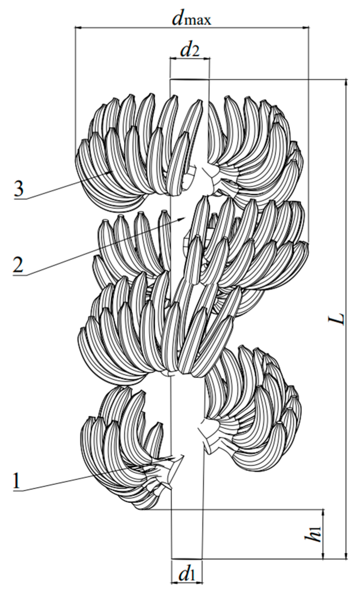
2.1. Planting Characteristics and Morphological Parameters of Banana Bunches

To ensure the applicability of the developed banana bunch conveying device in banana garden operations, field measurements were conducted from 18 to 19 November 2023, in Mazhang District (Zhanjiang, CN, China). Utilizing a measuring tape with a 5 m range, the measured row spacings for the two gardens were found to be 3.5 m and 4.2 m, respectively. After the banana harvest, the bunch primarily consists of fruit, fruit shafts, and comb handles. To establish the design parameters for a banana bunch transportation device, the shape characteristics of the Cavendish variety were quantified. The Cavendish variety is more common in China, and its morphological characteristics are more representative. The measurement parameters depicted in Figure 1 included the weight of the banana bunch, the maximum banana bunch diameter, the bottom diameter of the fruit shaft, the top diameter of the fruit shaft, and the distance from the bottom of the fruit shaft to the comb tail. The morphological data collected through these measurements are presented in Table 1.

2.2. Overall Structure and Working Principle

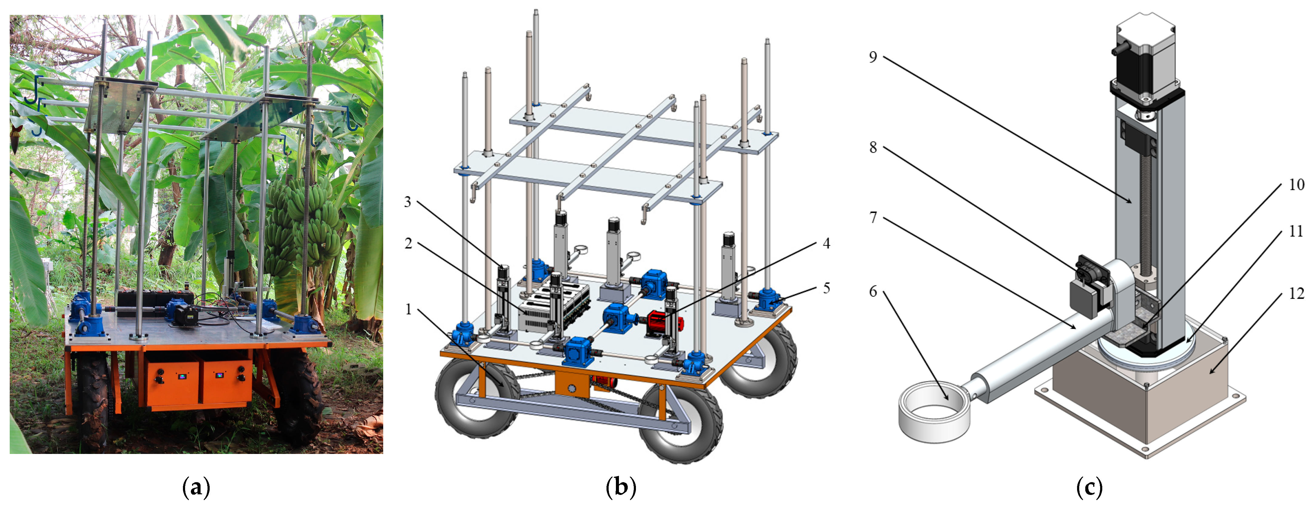
2.2.1. Overall Structure

Based on the cultivation techniques and morphological characteristics of bananas, the designed banana bunch transportation device primarily consists of a walking mechanism, a lifting mechanism, and fruit shaft bottom-fixation mechanisms. In comparison to tracked transport trolleys, wheeled transport trolleys exhibit superior attributes such as higher speed, greater traction, better mobility, higher reliability, lower noise, and minimal ground damage [24,25]. Therefore, this study chose the wheeled transport trolley. The entity diagram of the transport device is shown in Figure 2a, and the CAD drawing of the overall structure is shown in Figure 2b. The main technical parameters of the banana bunch transportation device with lifting and automatic bottom-fixing fruit shaft are shown in Table 2.

2.2.2. Working Principle

The low-damage transportation of bananas focuses on minimizing collisions between bunches and reducing manual operations that cause mechanical injuries, such as compression or friction between workers and banana fruit [26]. After the banana bunches are harvested, a rope knot is tied at the top. The bunches are then placed on the ground, and the knot is attached to the hanger on the suspension frame. The lifting mechanism raises the bunches to a specific height, enabling their suspended transportation.
During the starting phases, as well as during transportation, banana bunches experience oscillations due to gravity and inertia, which can lead to collisions between bunches, resulting in mechanical injuries to the banana fruit, as depicted in Figure 3a. Therefore, for banana bunches in suspension, it is necessary to fix their shaft to restrict their freedom during transportation, thus reducing oscillations. The bottom fixation of the fruit shaft is depicted in Figure 3b.

2.3. Design of Banana Bunch Transportation Mechanism

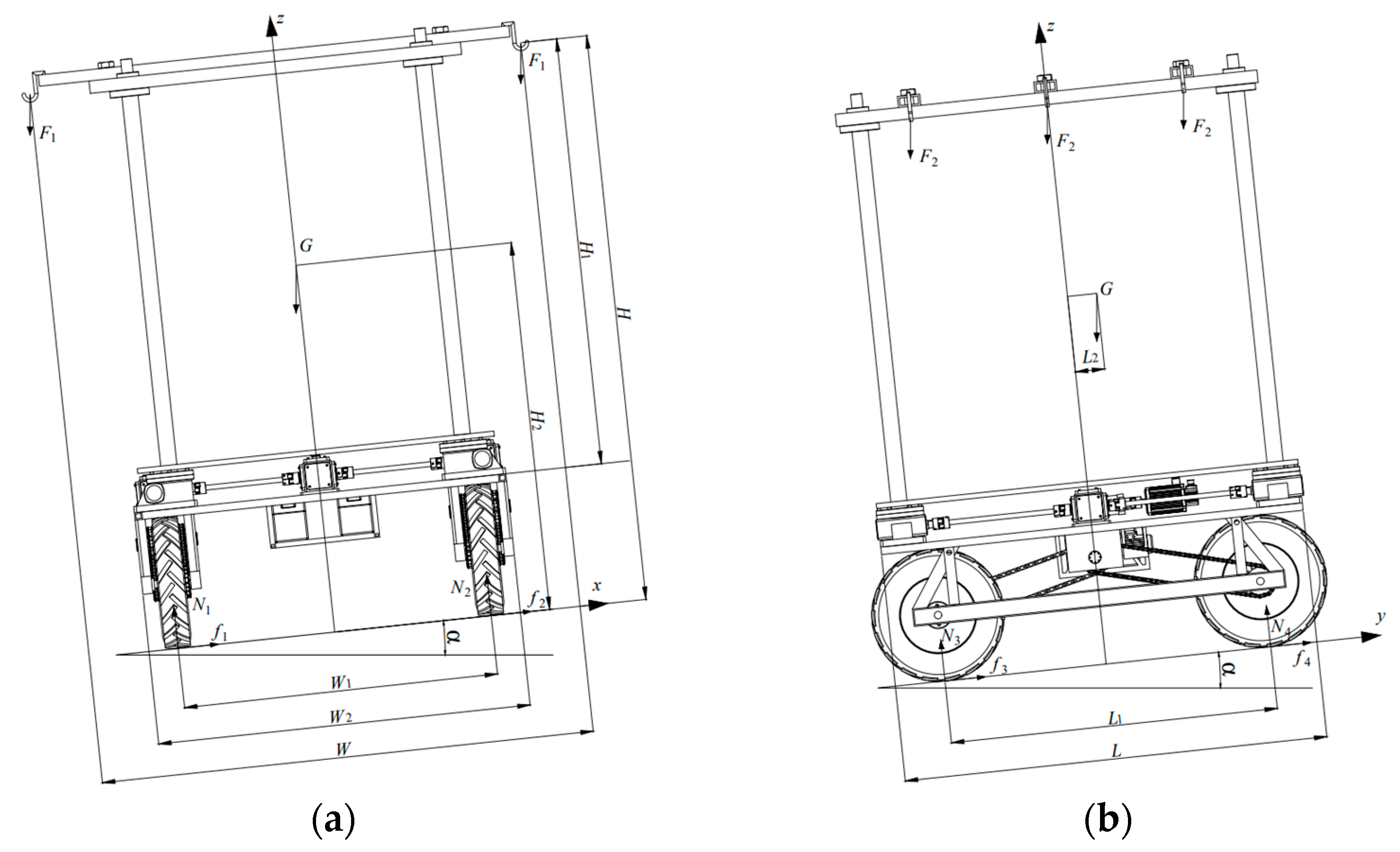
2.3.1. Anti-Overturning Design

Based on the field measurements of inter-row distances in banana orchards, an initial estimation for the width of the transportation device was determined to be within the range of 1200 mm to 1500 mm, and its length was found to be between 1500 mm and 1700 mm. The ground slope for hilly terrain ranges from 2° to 6°, while mountainous terrain has inclinations between 6° and 25°. The banana bunch transportation device is susceptible to overturning during operation, necessitating a thorough analysis of the anti-overturning wheeling trolley parameters. This analysis simplifies the system to focus on the forces acting on the device when transporting bunches at their highest point, with the vehicle traveling at a constant speed on a slope with a maximum angle α of 25°. The device experiences both lateral and longitudinal motion on this inclined surface, and the corresponding models for these movements are illustrated in Figure 4.
When the transportation device is in a lateral motion with a fully loaded banana bunch attached to the left hook, approaching the critical state of tipping, the supporting force N2 on the right side becomes zero [27]. Consequently, the torque equation for the tipping edge can be derived as follows:
2 F 1 H + G H 2 sin α 0.5 F 1 W 1 + W 2 + G W 1 cos α = 0
In the equation, F1 is the total weight of three bunches of bananas on one side; G is the total weight of the transportation device; W is the transverse spacing of the hook; W1 is the distance between the left and right wheels; W2 is the total width of the walking mechanism; H is the height of the hook to the ground; and H2 is the height of the center of gravity of the conveying device. W2 ≈ 1.1–1.2 W1, W = W2 + 2dmax.
Similarly, when the transportation device is in a longitudinal motion with a full load, the torque equation for the tipping edge can be expressed as
F 2 H sin α 0.5 F 2 L 1 d max cos α + G H 2 sin α G 0.5 L 1 + L 2 cos α = 0
In the equation, F2 is the total weight of two banana bunches hanging on the back; dmax is the maximum diameter of the banana bunch; L1 is the front and rear wheel spacing; and L2 is the center of gravity offset distance of the transportation device.
The calculated wheelbases in two critical states are as follows:
W 1 1360.64   mm L 1 1243.73   mm
Considering the efficiency of the transportation device, its applicability to small banana orchards with row spacing less than 2.5 m, and the requirement for good maneuverability, the walking mechanism of the device is designed with a left-to-right wheel spacing of 1365 mm, a total chassis width of 1500 mm, and a front-to-rear wheel spacing of 1500 mm, with the overall length of the vehicle being 1700 mm.

2.3.2. Design of Lifting Mechanism

To ensure that the banana bunches can be suspended and transported on the flatbed cart, the lifting mechanism’s height adjustment must exceed the maximum height of the bunch.
H L max
In addition, a certain height allowance must be provided to ensure the fruit shaft bottom-fixation mechanisms have adequate space for grasping the bottom of the shaft. Taking these factors into account, a SWL2.5T screw synchronous lifting mechanism with a height adjustment of 1500 mm was chosen, capable of handling a maximum load of 500 kg. The standard screw parameters for this model are Tr30 mm × 6 mm, with a gear ratio of 1:12 and a transmission efficiency of 0.14%. The selection of the work motor was based on the chosen lifting mechanism model and operational requirements. Given the maximum input speed of 1500 rpm, the calculated lifting speed of the mechanism is 0.0125 m/s. The calculation formula for motor power is as follows:
P = F × v
The calculated motor power is 0.54 KW. During the transportation of banana bunches, due to the uneven ground of the banana orchard, it is possible to cause the banana bunches to jump up and down, which will give rise to a strong impact load on the screw lift. Thus, it is a working condition with great inertia. Based on the above conclusion, the service factor range is 1.5–3.0, and the service factor calculation formula is
K 1 = P 1 / P
P1 is the power of the selected motor. According to the above requirements and the working conditions of the mobile platform, a 110BL DC brushless motor with the following specifications was selected: 48V, 1 kW, 1500 r/min. The vertical movement of the lifter is facilitated by a nut on the guide screw. To suspend the bunch, a suspension mechanism is installed on the four nut-bearing rods, consisting of three crossbars equipped with hooks. To prevent mechanical damage from rigid collisions between the banana fruit, the walking mechanism, and the fruit shaft fixation mechanism during the lifting process, the length of the crossbars in the suspension mechanism is designed to be approximately the sum of the bunch’s maximum diameter, dmax, and the width of the walking mechanism. The spacing between the two crossbars is also strategically positioned based on the maximum diameter of the bunch [28].

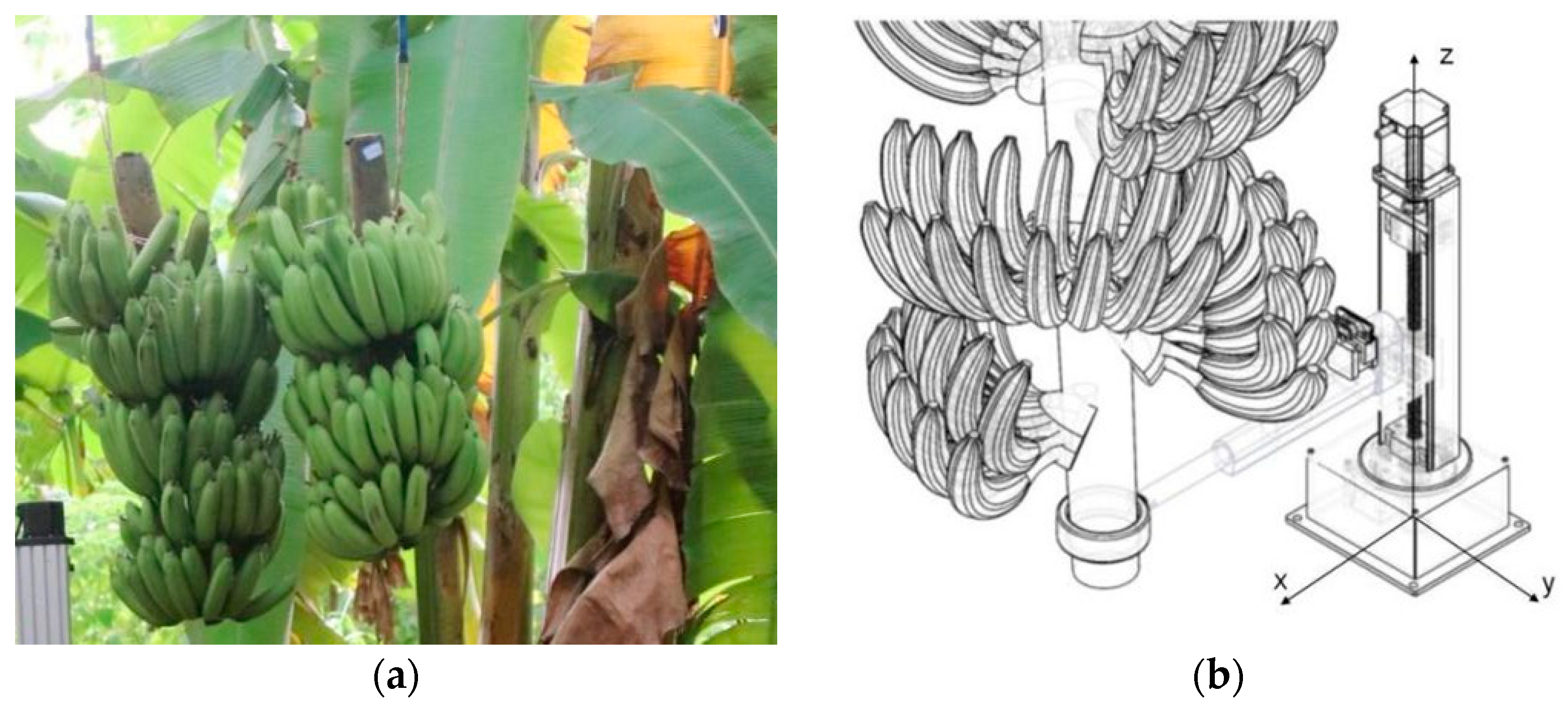
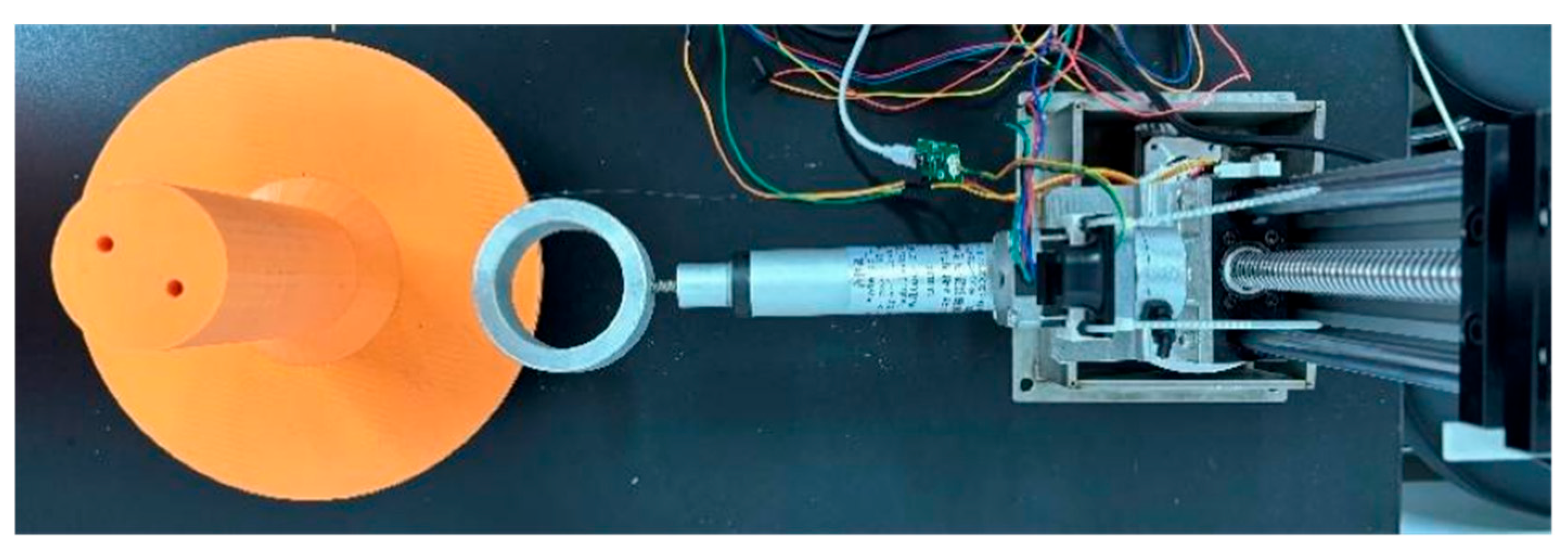
2.3.3. Design of Fruit Shaft Bottom-Fixation Mechanism

This study, based on the morphological parameters measured in Table 1, selected a linear module with a travel of 200 mm and a maximum vertical load capacity of 20 kg for the mechanism responsible for motion along the z-axis. For the xy plane motion, an electric telescopic rod with a stroke of 150 mm was selected. To accommodate the inherent curvature of the fruit shaft and increase the tolerance for securing its base, the inner diameter of the sleeve fixing the fruit shaft was set to 65 mm. The sleeve thickness was determined to be 30 mm, taking into account the measured distance from the bottom of the fruit shaft to the end of the tail pectinate.
During the initial acceleration of the transportation device, unfixed banana bunches experience a significant angular acceleration around the hook, resulting in a shock load on the bottom of the fruit shaft fixation mechanism. Consequently, the stepper motor that controls the linear module to rotate around the z-axis must have sufficient holding torque to ensure the stability of the system under the shock load. To investigate the maximum angular acceleration experienced by the banana bunch during the initial stage of transportation, a dynamic analysis model was constructed. The model involved simplifications of both the banana bunch and the transportation mechanism. The latter was approximated as a slider with a hook, moving linearly along a guide rail, and the banana bunch was represented by a 30 kg circular cylinder for the purposes of analysis. A nylon knot was assembled on the round table to hang on the hook of the slider. The simplified three-dimensional models above were established and assembled in Solidworks2022SP5.0 software [29]. In this simulation, this study employed Solidworks Motion to conduct a dynamic simulation of the banana bunch’s motion from the transport device’s stationary state to the uniform speed. The simulation duration was set at 20 s, with the sliding platform fixed and Earth’s gravity accounted for. This simulation incorporated the coefficient of friction between the nylon tie and aluminum hook, as well as the parameters of the walking mechanism’s motor. The simulation resulted in a graph depicting the angular acceleration and angular velocity curves, as illustrated in Figure 5.
According to the above figure, the peak value of the swing angular acceleration of the banana bunch, αmax, is in the starting stage of the brushless DC motor, specifically at 5.394 rad/s2. This allows us to calculate the linear acceleration at the bottom of the fruit shaft, denoted as at; its calculation formula is as follows:
a t = α max × L 3 = 5.394   m / s 2
In the formula, L3 is the length of the simplified banana bunch model. During the impact condition, the instantaneous angular acceleration at the bottom of the fruit shaft, α1, is measured to be 9.532 rad/s−2. Utilizing the mass properties feature in Solidworks, we determined the moment of inertia of the electric linear actuator, sleeve, and linear module about the z-axis, Izz = 0.195 kg·m2. Consequently, the torque acting on the rotating disk can be calculated as follows:
T = α 1 × I zz
The gear system, a prevalent component in mechanical equipment, plays a pivotal role in transmitting power, and its operational safety and reliability are of paramount importance, as they directly impact the overall equipment lifespan and efficiency [30]. Given that the holding torque for stepper motors in the 42 series and below ranges from 0.13 N·m to 0.7 N·m, and the torque generated by the rotating disk is 1.859 N·m, which corresponds to the instantaneous torque of the large gear, T2 = T = 1.859 N·m. With a selected gear ratio i = 5 and an estimated module m = 1, we calculated the number of teeth on the small gear, Z1 = 16, and the large gear, Z2 = 80. The gear width, b, was measured to be 10 mm.
The transmission ratio relationship of gear meshing is as follows:
i = z 2 z 1 = T 2 T 1
In the formula, T1 is the instantaneous torque of pinion. After calculation, T1 = 0.372 N·m. The stepper motor that controls the rotation of the fruit shaft bottom-fixation mechanism needs to keep the torque T3 greater than T1. Considering the working environment of the system and its service factor K2 = 1.2–1.5 [31]. The calculation formula of the actual holding torque of the stepper motor, T3, is as follows:
T 3 = K 2 × T 1
The service factor K2 is set to 1.4, and the required holding torque for the step motor is set at 0.521 N·m. Consequently, we selected a small-sized stepper motor with a stepping angle of 1.8° and a holding torque of 0.55 N·m, specifically the 42BYGH47 model, for its z-axis rotation control functionality.

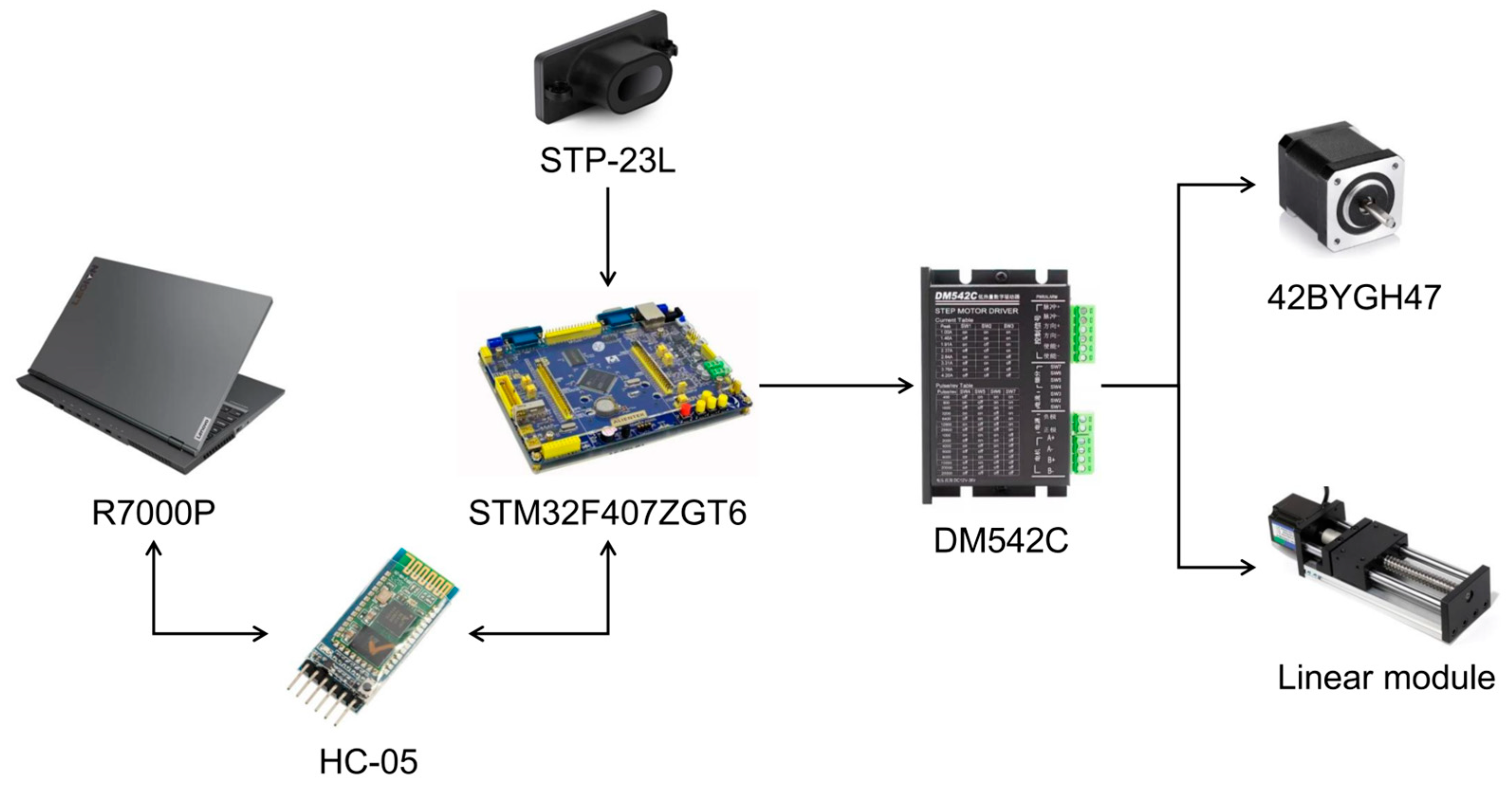
2.4. Control System Design

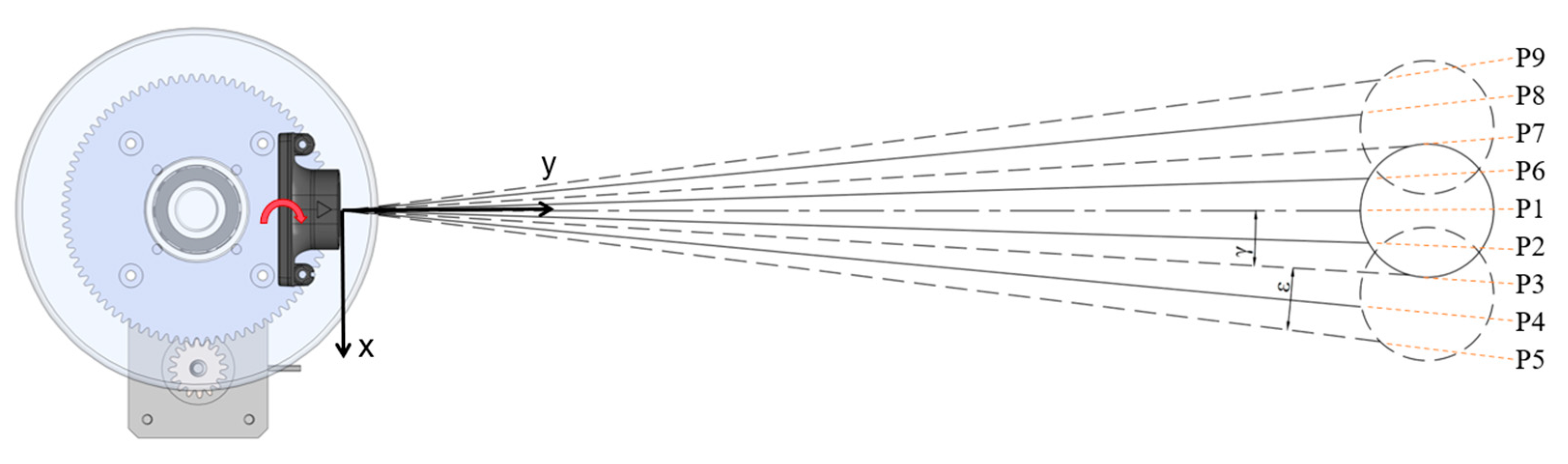
2.4.1. Scanning Distance Information Detection System

The hardware architecture of the scanning distance information detection system, depicted in Figure 6, consists of three principal components: the distance data acquisition module, the actuator driver, and the control unit. The distance information is collected by an STP-23L ranging module. The limit collision module is selected as the position limit sensor. The driving actuator includes an actuator and a driver. The actuator includes 42-stepper motors and linear modules. The driver is DM542C. The control system is composed of a main controller (Lenovo R7000P) and a subordinate unit (STM32F407ZGT6). The distance measurement module is mounted on an electric telescopic rod, where it undergoes horizontal scanning in a rotationally multi-point manner. STP-23L is facilitated by a 42-stepper motor, which synchronously rotates with the fruit shaft bottom-fixation mechanism. This allows for improved recognition and distance measurement of the bottom of the fruit shaft.
Given the approximately cylindrical nature of the fruit stalk base, the distance measurement module requires a rotation angle γ with respect to the stalk’s fixing mechanism to acquire multiple distance datasets for center point determination. The module’s rotation angle must also account for the shaft’s curvature and potential deviation from vertical alignment when suspended, necessitating a compensation angle ε in addition to γ. This results in a single-side rotation angle of ε + γ, as illustrated in Figure 7, for accurate scanning of the bottom of the fruit shaft. A horizontal rectangular coordinate system with STP-23L as its origin was established. The rotation angle ε + γ was set to 7.2°, with each independent rotation being 1.8°. The nine positions are labeled P1 through P9, with P1 serving as the initial position. After scanning P1, the mechanism rotates clockwise to P2 (1.8°) for further scanning, repeating this pattern until P5 is reached. Following that, a counterclockwise rotation of 9° led to P6, where the same scanning process is performed until P9. Distance data from all positions are uploaded to the PC. Finally, STP-23L returns to its initial position by rotating counterclockwise 7.2°.

2.4.2. Fruit Shaft Bottom Recognition and Center Position Acquisition Method

If the actual distance data obtained through scanning fall within the range of 250 mm to 350 mm, this position can be considered as the bottom of the fruit shaft. To identify the central position of the fruit shaft bottom, a bottom-scanning distance measurement technique is employed, which yields multiple distance values from various fruit shaft surface points. These distances are then transformed into planar coordinates. A least-squares method is applied to fit a circle to these points [32], resulting in the general formula for a planar circle:
x 2 + y 2 + a 1 · x + a 1 · y + a 3 = 0
Assuming that the scan detects n points, there is the following system of equations:
x 1 2 + y 1 2 + a 1 · x 1 + a 1 · y 1 + a 3 = 0 x 2 2 + y 2 2 + a 1 · x 2 + a 1 · y 2 + a 3 = 0 x n 2 + y n 2 + a 1 · x n + a 1 · y n + a 3 = 0
This system of equations is written in matrix form:
x 1 y 1 1 x 2 y 2 1 x n y n 1 a ( 1 ) a ( 2 ) a ( 3 ) = x 1 2 y 1 2 x 2 2 y 2 2 x n 2 y n 2
X · A = Y
According to the least-squares method, the calculation equation of A matrix is as follows:
A = X T X 1 X T Y
By solving for the elements of matrix A, the center and radius of the fitted circle are derived. Utilizing this fitted circle, the coordinates and radius of the fruit shaft bottom’s center are determined. The identification of the fruit shaft bottom’s central position is fundamental for the automatic fixation process.

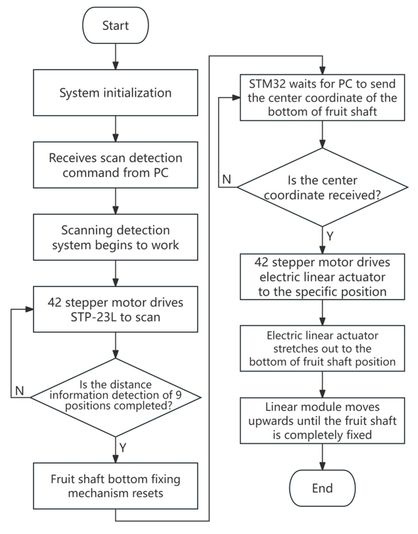
2.4.3. Automatically Fixed Fruit Shaft Bottom-Control System

All of the stepper motors of the fruit shaft bottom-fixation mechanism are governed by the microcontroller STM32407ZGT6, and the sequential process of the automatic fixing system is depicted in Figure 8.
During program execution, the system initializes as the microcontroller receives scanning commands from the PC. The linear module ascends until the STP-23L module receives a distance below 350 mm. At position P1, STP-23L begins to receive five times the distance information. Subsequently, the 42-step motor drives the STP-23L to rotate to predetermined positions, where it performs distance measurements at each location. The microcontroller controls the linear module to reverse and stops working when the sliding table of the linear module triggers the collision sensor. Upon receipt of the center coordinate of the fruit shaft bottom from the PC, the microcontroller translates this information into the corresponding pulse count for each stepper motor. Following the completion of the target pulse count by the electric linear actuator and the 42-stepper motor, the linear module drives the sleeve upward until it secures the fruit shaft.

2.5. Field Test

2.5.1. Experimental Conditions

The field trials were conducted in April 2024 at the Agricultural Engineering Building of South China Agricultural University and the university’s small banana orchard. The trials featured four banana bunches and 3D-printed replicas of simulated fruit shafts. The simulated transportation device traveled inclines with an approximate slope of 15 degrees. The camera employed for capturing the oscillation angle of the banana bunches was an EOS R6 Mark II.

2.5.2. Experimental Method

(1)
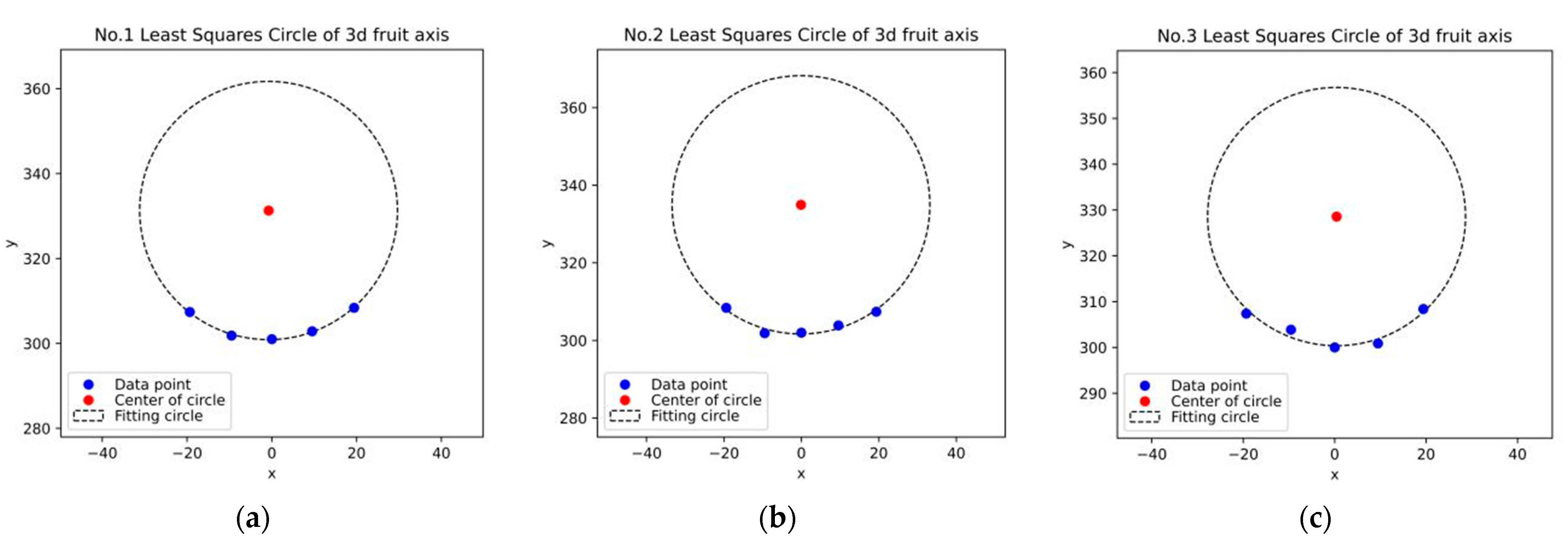
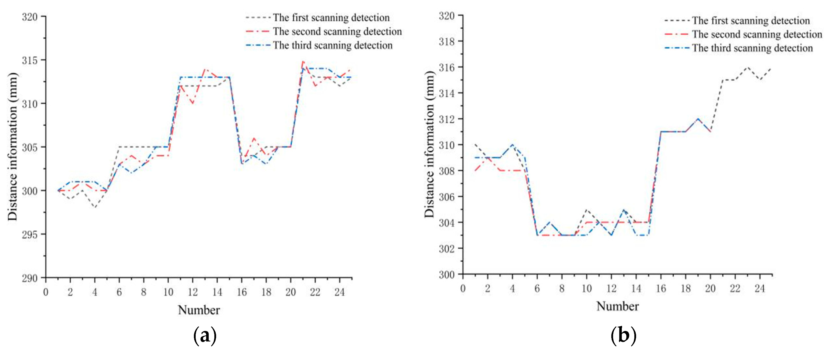
To investigate the performance of the scanning distance information detection system in identifying the bottom and center of a fruit shaft, a 3D-printed replica of a 30 mm radius fruit axis was positioned 300 mm away from the STP-23L distance measurement module. The system conducted three independent scanning experiments on the mock fruit shaft. Employing the least-squares method, the coordinates obtained from the surface scanning were fitted to a circle, resulting in the estimated radius and center coordinates. The error between the fitted radius and the actual one was calculated using the following equation:
δ = r r s r × 100 %
In the equation, r is the actual radius of the simulated fruit shaft, and rs is the radius of the fitted circle.
(2)
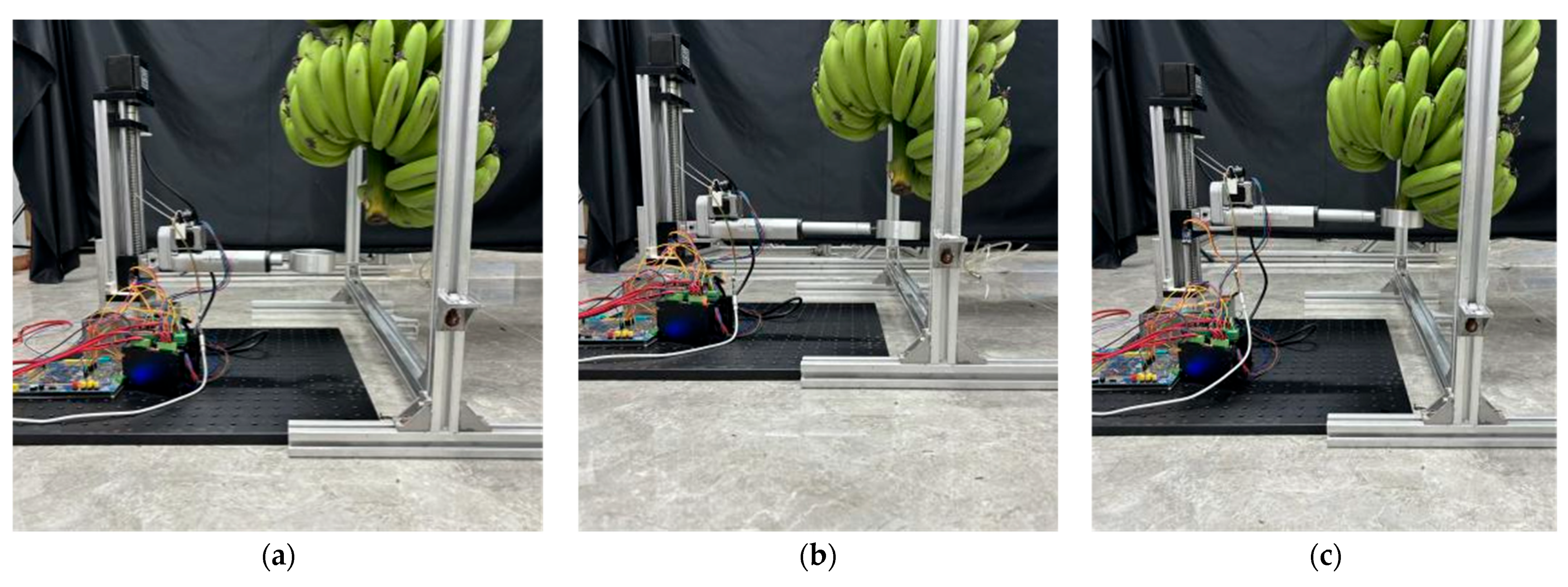
To evaluate the performance of the fruit shaft bottom-fixation mechanism, it was mounted on a flat surface. This study involved dividing four banana bunches into four groups, with each group subjected to distinct fixation scenarios: one where the fruit shaft bottom was aligned with the mechanism and another where the rope knot of the suspended bunches was offset by 20 mm to the right. For each condition, three trials were conducted horizontally, and the success rate of fruit stalk bottom fixation was determined. The equation for calculating this success rate is as follows:
S = N S N × 100 %
In the equation, NS is the number of successful trials at the bottom of the fixed fruit shaft, and N is the total number of trials.
(3)
To assess the stability of the transportation device against overturning, it was tested with full loads on one side, traveling slopes both longitudinally and laterally. To evaluate the impact of the fruit shaft bottom-fixation mechanism on banana bunch transportation, a field test was conducted, comparing the stability of field transportation with a fixed shaft bottom to that without fixation.
(4)
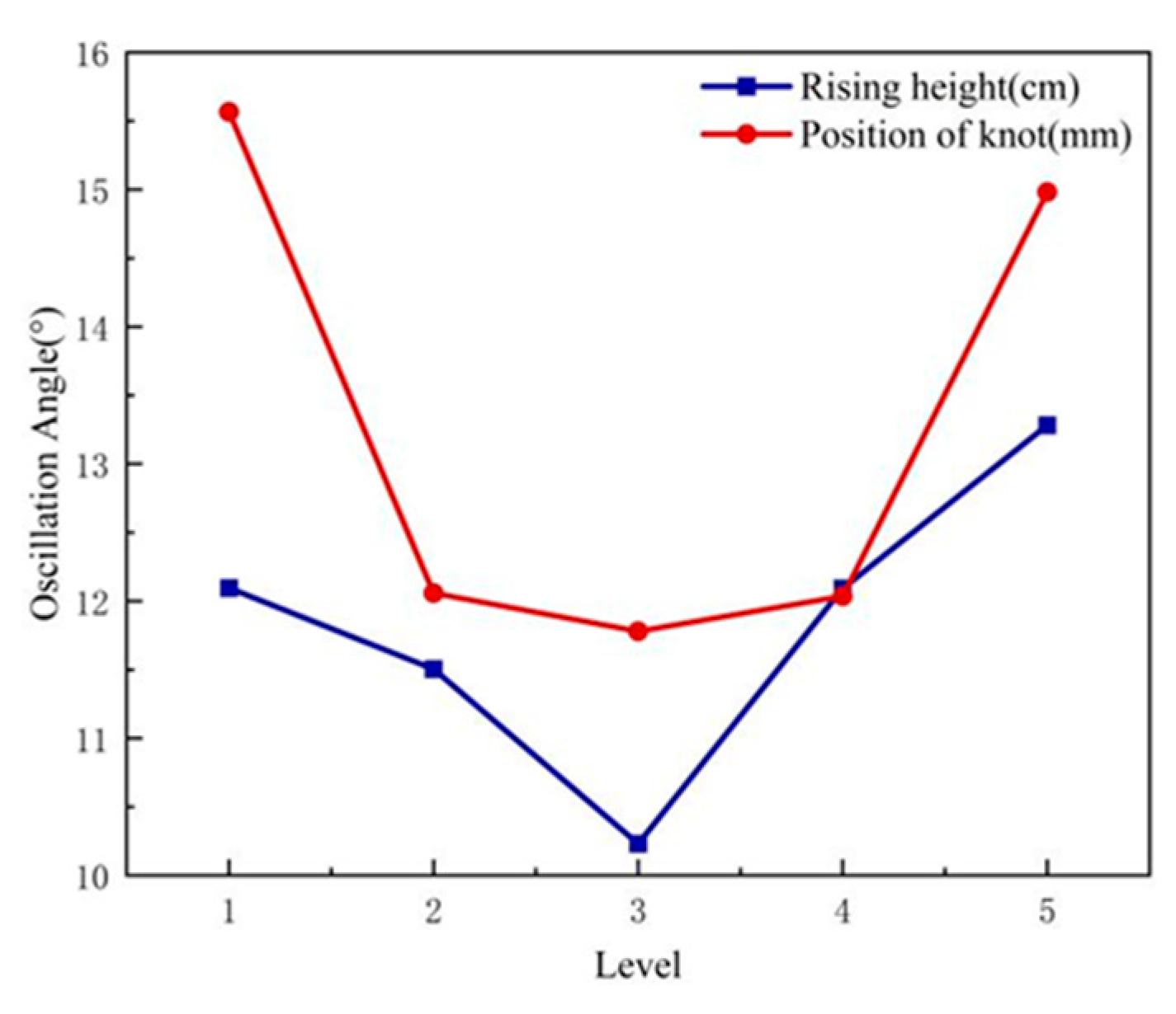
High-speed continuous shooting with the EOS R6 Mark II was employed to measure the banana bunch oscillation angle during the initial stage of the transportation device. To minimize the oscillation angle and thereby reduce collision probabilities and impacts on the fruit shaft bottom-fixation mechanism, a multifactorial experiment was conducted, varying the maximum travel speed of the device, the distance between the rope knot and the top of the shaft, and the height at which the bunches were raised. Considering both the transport efficiency of the banana bunches and the performance of the walking mechanism, an operational speed range of 3 km/h to 5 km/h of the device was selected. In the preliminary single-factor experiments, the range of the rising height for the banana bunch was set at 80 cm to 92 cm, and the distance between the rope knot and the top of the shaft was within the range of 100 mm to 220 mm, as detailed in Table 3 showing the coding of the single-factor experimental levels.
Based on single-factor tests, the following parameter ranges were determined: maximum speed between 3 km/h and 5 km/h, height between 83 and 89 cm, and a rope knot distance from the shaft top between 130 and 190 mm. Employing the Box–Behnken design, this study considered the three factors as influential variables, using the minimum oscillation angle as the test criterion for minimal impact. Because of the difficulty of maintaining a constant operating speed during actual transportation, this study replaced a specific speed with a specific speed range. Each level was repeated three times, and the average was calculated, as shown in Table 4.

3. Results

3.1. Performance Test of Scanning Distance Detection System

The field trial of the scanning distance detection system for fruit shaft bottom identification and center position localization is depicted in Figure 9. After starting the STP-23L serial port, distance information was collected, and the fitting circles obtained from three scans are shown in Figure 10.
Table 5 presents the center coordinates of the fitted circles and the discrepancies between the fitted circle radii and the actual ones, as derived from three scans.
The table reveals that the relative error between the two measurements is less than 15%. The diameter of the fruit shaft fixed sleeve designed in this study is 136.383% of the maximum diameter at the bottom of the fruit shaft in Table 1, indicating that the error is within the acceptable range of automatic fixing the bottom of the fruit shaft.

3.2. Field Performance Test of Fruit Shaft Bottom-Fixation Mechanism

In the first group of bunch trials, after processing the distance data obtained from the scanning, outliers beyond the bunch range were eliminated, resulting in both unbiased and biased distance information for the bunch, as illustrated in Figure 11.
When the banana bunch has no offset, the fruit shaft surface coordinates are represented by points P1, P2, P3, P6, and P7. In contrast, when a 20 mm lateral shift occurs, the distribution of these points on the fruit shaft surface is limited to P1, P2, P3, and P4. The field performance test scene of the fruit shaft bottom-fixing mechanism is shown in Figure 12.
The success rate of the automatic fixation test at the bottom of the fruit shaft is presented in Table 6, as shown below.
The success rate of fixing the fruit shaft bottom, as calculated by Equation (12), stands at 95.83%, indicating a favorable performance of the mechanism. Upon examination of Table 6, it is evident that the standard deviation of fitted circle coordinates with offset for Banana bunch Number 1 is abnormal. The fitted circle center coordinates of the failure group were (2.900, 352.186) and the fitted circle radius was 50.432 mm, which does not align with reality. This anomaly occurred due to a single banana fruit segment that was damaged and detached, landing at position P8 at the bottom of the fruit shaft. Removing this fallen segment in the test groups allowed for the successful fixation of the fruit shaft bottom.

3.3. Test Results and Analysis of Operation Stability of Banana Bunch Conveying Mechanism

The conveying mechanism, as illustrated in Figure 13a, transported one side of fully loaded banana bunches laterally across a slope of approximately 15°, while Figure 13b depicts the mechanism carrying rear-side fully loaded bunches along a slope of around 15°.
In the two walking states, the conveying mechanism still maintained a relatively stable attitude for transportation, and there was no tendency to capsize during operation.

3.4. Comparative Test Results and Analysis of Banana Bunch Transportation Stability

The results of the comparison test of no fixed transportation and fixed transportation at the bottom of the banana fruit shaft are shown in Figure 14.
During the initial phase of field transportation by the conveying device, the banana bunch with a fixed bottom of the fruit shaft showed minimal oscillation, whereas another with an unfixed bottom exhibited significant swinging due to inertia. This swinging tendency posed a risk of mechanical damage to the banana fruit, hence justifying the necessity of fixing the fruit shaft bottom.

3.5. Analysis of Single-Factor Experiments

The single-factor experiment on the rising height of the banana bunch was conducted under the condition that the walking mechanism operated at its maximum speed, with the rope knot positioned 160 mm from the top of the fruit shaft. The single-factor experiment on the distance from the rope knot to the top of the fruit shaft was conducted under the condition that the walking mechanism operated at its maximum speed, with the rising height of the banana bunches set at 86 cm. Each level of the aforementioned single-factor experiments was repeated five times to analyze the average results, aiming to evaluate the influence of the rising height of the banana bunch on the swing angle and the impact of the distance from the rope knot to the top of the fruit stalk on the oscillation angle, as illustrated in Figure 15.
Regarding the impact of the rising height of the banana bunch on the oscillation angle, the oscillation angle decreases within the range of 80 cm to 86 cm of rising height but increases within the range of 86 cm to 92 cm. For the influence of the distance between the knot position and the top of the fruit shaft on the oscillation angle of the banana bunch, the oscillation angle of the banana bunch decreased in the range of 100 mm to 160 mm from the top of the fruit shaft but increased in the range of 160 mm to 220 mm. Based on the results of the single-factor analysis, the determined height range for rising the banana bunch is 83 cm to 89 cm, and the distance range from the knot position to the top of the fruit shaft is 130 mm to 190 mm.

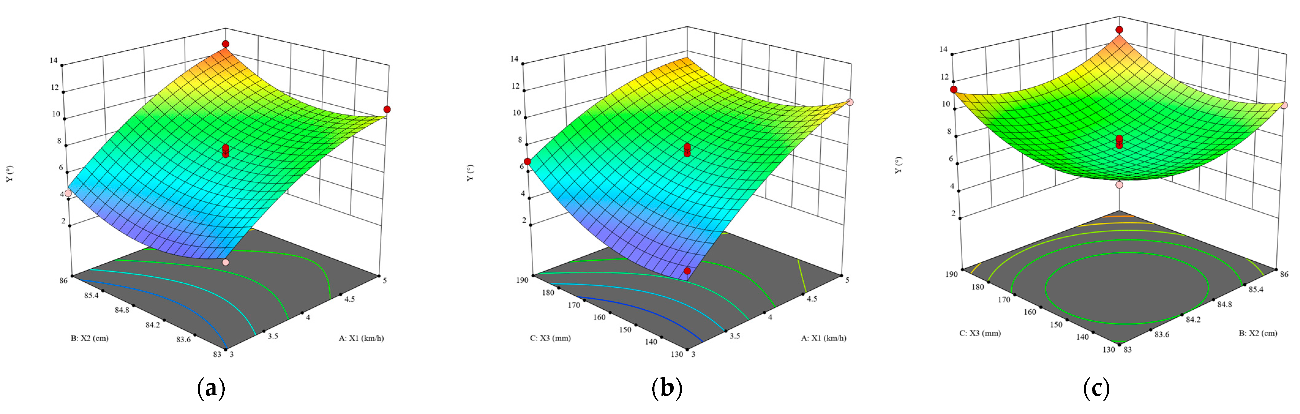
3.6. Multivariate Test Results and Analysis of Variance

Table 7 summarizes the multi-factor test plan and results.
Using the Design-Expert 13 software, the collected data were processed and analyzed to establish a relationship between the oscillation angle and maximum speed, the rising height of the banana bunch, and the distance between the rope knot and the top of the fruit shaft. Subsequently, a variance analysis was conducted on the established model. The variance analysis of the regression equation of the response surface of the oscillation angle is shown in Table 8.
According to the results of Table 8, after removing the insignificant items, the regression equation of the oscillation angle Y expressed by the coded value is as follows:
Y = 7.50 + 3.32 X 1 + 0.6509 X 2 + 1.02 X 3 0.9218 X 1 X 3 1.11 X 1 2 + 1.68 X 3 2 + 1.75 X 3 2
The interaction between the three test factors and the oscillation angle is depicted in Figure 16.
In order to improve the durability of the fruit shaft bottom-fixation mechanism, considering the transport efficiency of banana bunches, a regression equation Y was derived using Design-Expert 13 software, subject to constraints of maximum delivery speed and minimum oscillation angle. The optimal parameter set includes a delivery speed of 4.9–5.1 km/h, a height of 84.04 cm for the bunch to rise, and a distance of 159.13 mm from the fruit stem to the knot. This configuration resulted in an oscillation angle of 9.526° during the initial phase of transportation. Due to the practical limitations in precisely controlling the height of the banana bunches during transportation and the position of the knot relative to the top of the fruit shaft, a range of 81–84 cm was established for the bunch rise height, and a knot placement at 150–160 mm from the top of fruit shaft was determined.
min Y X 1 , X 2 , X 3 s . t X 1 = 4.9 5.1   k m / h 81   cm X 2 84   cm 150   mm X 3 160   mm
Through field trials, the measured oscillation angle of the banana bunch under these conditions was 8.961°, with a deviation of 5.93% between the result of response surface analysis and experimental values. This discrepancy can be primarily attributed to inconsistencies in the terrain during the walk through the banana orchard, specifically the variation in surface irregularities. The relative error of the assessment criteria was all below 15%, which remains within the acceptable range for agricultural machinery, thus confirming the model’s reliability.

4. Conclusions

This study aims to address the issues of high labor intensity, high labor costs, low transportation efficiency, and high rate of banana damage during the transportation of banana bunches, proposing an innovative banana bunch transportation device. The device includes a lifting mechanism, an automatic system for fixing the bottom of the fruit shaft, and a walking mechanism. Based on considerations of anti-overturning boundary conditions, the morphological characteristics of banana bunches, simulations of banana bunch oscillation dynamics, and the features of the fruit shaft bottom, we have completed the construction of the entire system and conducted field tests. The specific conclusions are as follows:
(1)
Using the dynamics simulation in Solidworks Motion, the maximum angular acceleration of the bunch during startup was determined to be 5.394 rad/s2. Based on this value and the gear ratio, 42BYGH47 was selected for controlling the rotation of the fruit shaft bottom-fixation mechanism.
(2)
In the conducted field trials, the surface coordinates of the multi-point scanning for the simulated fruit shaft were successfully fitted into a circle, with an error margin of less than 15% between the derived parameters and the actual ones. This outcome is well within the acceptable error range of the shaft bottom-fixing mechanism. The positioning accuracy for the shaft bottom center and the automatic fixation success rate of the fixation mechanism reached 95.83%, indicating a satisfactory fixation performance. The overall system’s field test validated the robustness of the transportation device against overturning. Comparative trials between fixed and non-fixed banana bunches underscored the significance of securing the shaft bottom during the banana bunch transportation process.
(3)
To enhance the durability of the bottom-fixation mechanism for the fruit shaft, a multi-factor experiment was employed to identify the optimal parameter combination under the conditions of maximum transportation efficiency and minimum oscillation angle. The rope knot was tied 160 mm from the top of the fruit shaft, and the rising height of the banana bunches was measured at 84 cm. The results of the response surface analysis showed a 5.93% error in comparison to field trials, indicating the reliability of the response surface analysis model. Furthermore, the designed device complies with the horticultural requirements of banana orchards. This study provides valuable theoretical guidance and practical insights for the development of banana bunch transportation mechanisms in orchards.

Author Contributions

Conceptualization, J.D. and X.X.; methodology, W.L. (Weiqin Li) and X.X.; software, W.L. (Weiqin Li) and J.Y.; validation, W.L. (Weiqin Li), X.M., W.L. (Weixi Li) and X.X.; formal analysis, W.L. (Weiqin Li); investigation, W.L. (Weiqin Li), W.L. (Weixi Li), J.Y. and X.M.; resources, J.D., X.X. and Z.Y.; data curation, W.L. (Weiqin Li); writing—original draft preparation, W.L. (Weiqin Li); writing—review and editing, X.X. and J.D.; visualization, W.L. (Weiqin Li); supervision, J.D.; project administration, J.D., Z.Y. and X.X.; funding acquisition, Z.Y. and J.D. All authors have read and agreed to the published version of the manuscript.

Funding

This research was funded by the Open Competition Program of the Top Ten Critical Priorities of Agricultural Science and Technology Innovation for the 14th Five-Year Plan of Guangdong Province, grant number 2022SDZG03; the China Agriculture Research System of MOF and MARA, grant number CARS-31-11; and the China Scholarship Council.

Institutional Review Board Statement

Not applicable.

Data Availability Statement

The data presented in this study are available upon request from the corresponding author.

Conflicts of Interest

The authors declare no conflicts of interest.

References

  1. Nascimento, R.E.A.; Carvalheira, M.; Crespo, J.G.; Neves, L.A. Extraction and Characterization of Cellulose Obtained from Banana Plant Pseudostem. Clean Technol. 2023, 5, 1028–1043. [Google Scholar] [CrossRef]
  2. Aher, R.; Dethe, A.; Chavhan, R.; Hinge, V.; Dhutraj, S. Molecular elucidation of sigatoka disease resistance in diverse banana (Musa spp.) genotypes using molecular markers and genetic diversity analysis. Sci. Hortic. 2024, 336, 113446. [Google Scholar] [CrossRef]
  3. Ahmad, T.; Danish, M. Prospects of banana waste utilization in wastewater treatment: A review. J. Environ. Manag. 2018, 206, 330–348. [Google Scholar] [CrossRef]
  4. Jiang, Y.; Yang, Z.; Xu, X.; Xie, B.; Duan, J. Spreading model of single droplet impacting the banana leaf surface and computational fluid dynamics simulation analysis. Comput. Electron. Agric. 2024, 223, 109113. [Google Scholar] [CrossRef]
  5. Choudhury, N.; Nickhil, C.; Deka, S.C. Comprehensive review on the nutritional and therapeutic value of banana by-products and their applications in food and non-food sectors. Food Biosci. 2023, 56, 103416. [Google Scholar] [CrossRef]
  6. Arunima, P.L.; Gopinath, P.P.; Lekshmi, P.G.; Esakkimuthu, M. Digital assessment of post-harvest Nendran banana for faster grading: CNN-based ripeness classification model. Postharvest Biol. Technol. 2024, 214, 112972. [Google Scholar] [CrossRef]
  7. Velame, K.V.C.; Rocha, A.D.J.; Ferreira, M.D.S.; Haddad, F.; Amorim, V.B.O.; Pestana, K.N.; Ferreira, C.F.; de Oliveira, S.A.S.; Amorim, E.P. Evidence of Correlation between Pathogenicity, Avirulence Genes, and Aggressiveness of Fusarium oxysporum f. sp. cubense in Banana “Cavendish” and “Prata” Subgroups. Horticulturae 2024, 10, 228. [Google Scholar] [CrossRef]
  8. Ma, C.; Zhang, Q.; Lv, D.-Z.; Song, J.; Fan, Q.; Tian, H.; Wang, M.-Y. Study of Factors Influencing the Oral Bioaccessibility of Commonly Used and Detected Pesticides in Bananas and Mangoes Based on in vitro Methods. Foods 2024, 13, 2019. [Google Scholar] [CrossRef]
  9. Opara, U.L.; Pathare, P.B. Bruise damage measurement and analysis of fresh horticultural produce—A review. Postharvest Biol. Technol. 2014, 91, 9–24. [Google Scholar] [CrossRef]
  10. Jahanbakhshi, A.; Yeganeh, R.; Shahgoli, G. Determination of Mechanical Properties of Banana Fruit under Quasi-Static Loading in Pressure, Bending, and Shearing Tests. Int. J. Fruit Sci. 2020, 20, 314–322. [Google Scholar] [CrossRef]
  11. Al-Dairi, M.; Pathare, P.B.; Al-Yahyai, R.; Jayasuriya, H.; Al-Attabi, Z. Evaluation of chemical quality attributes in bruised bananas during storage. Food Sci. Technol. 2024, 197, 115904. [Google Scholar] [CrossRef]
  12. Al-Dairi, M.; Pathare, P.B.; Al-Yahyai, R.; Jayasuriya, H.; Al-Attabi, Z. Postharvest quality, technologies, and strategies to reduce losses along the supply chain of banana: A review. Trends Food Sci. Technol. 2023, 134, 177–191. [Google Scholar] [CrossRef]
  13. Li, D. Postharvest commercialization treatment technology of banana. China Trop. Agric. 2006, 40–41. [Google Scholar] [CrossRef]
  14. Wang, W.; Wang, Y.; Shen, Y.; Cheng, L.; Qiao, J. The role of multi-category subsidies in cultivated land transfer decision-making of rural households in China: Synergy or trade-off. Appl. Geogr. 2023, 160, 103096. [Google Scholar] [CrossRef]
  15. Albiero, D.; Pontin Garcia, A.; Kiyoshi Umezu, C.; de Paulo, R.L. Swarm robots in mechanized agricultural operations: A review about challenges for research. Comput. Electron. Agric. 2022, 193, 106608. [Google Scholar] [CrossRef]
  16. Li, J.; Li, S.; Zhang, Y.; Liu, M.; Gao, Z. Development and test of hydraulic driven remote transporter. Int. J. Agric. Biol. Eng. 2021, 14, 72–80. [Google Scholar] [CrossRef]
  17. Saheb, M.; Morteza, A.; Arjang, J. Applying multi-criteria decision making method to analyze stability and mechanization patterns in small farms. Environ. Sustain. Indic. 2023, 20, 100295. [Google Scholar] [CrossRef]
  18. Guo, J.; Duan, J.; Li, J.; Yang, Z. Mechanized Technology Research and Equipment Application of Banana Post-Harvesting: A Review. Agronomy 2020, 10, 374. [Google Scholar] [CrossRef]
  19. Wang, Y. Research on Key Technology of Harvesting Machine in Flat Banana Plantation. Master’s Thesis, South China Agricultural University, Guangzhou, China, 2019. [Google Scholar]
  20. Yan, L.; Yang, Z.; Li, J.; Chen, C. Design and Test of Trailer Frame for Banana Conveying. J. Agric. Mech. Res. 2013, 35, 168–170. [Google Scholar]
  21. Yang, Z.; Li, J.; Wang, W.; Zheng, S.; Ding, L.; Xu, G. An Electric Banana Delivery System. CN201110333965.9, 20 June 2012. [Google Scholar]
  22. Zhu, L.; Li, Z.; Ma, Z.; Liu, S. Design and manufacture of wheeling trolley for banana transportation. J. Zhongkai Univ. Agric. Eng. 2016, 29, 1–4. [Google Scholar]
  23. Ren, W. Development of Small Tracked Vehicle for Banana Transportation in Field. Master’s Thesis, Zhongkai University of Agriculture and Engineering, Guangzhou, China, 2016. [Google Scholar]
  24. Shafaei, S.M.; Mousazadeh, H. Experimental comparison of locomotion system performance of ground mobile robots in agricultural drawbar works. Smart Agric. Technol. 2023, 3, 100131. [Google Scholar] [CrossRef]
  25. Fonseca, D.J.; Uppal, G.; Greene, T.J. A knowledge-based system for conveyor equipment selection. Expert Syst. Appl. 2004, 26, 615–623. [Google Scholar] [CrossRef]
  26. de Magalhães, M.J.M.; Abrahão, R.F.; Leal, P.A.M. Manual transportation within the plot and physical damages to bananas. Sci. Agric. 2004, 61, 32–35. [Google Scholar] [CrossRef]
  27. Geng, D.Y.; Sun, Y.C.; Li, H.B.; Mou, X.D.; Zhang, G.D.; Wang, Z.Y.; Lu, X. Design and experiment of crawler corn harvester for sloping fields. Trans. Chin. Soc. Agric. Eng. 2021, 37, 11–19. [Google Scholar]
  28. Valdés-Hernández, P.A.; Martínez-Rodríguez, A.; Suárez-Hernández, J.; Gómez-Águila, M.V. Theoretical Model of a Transportation System for Banana Bunches (Clusters) in Hillsides. Rev. Cienc. Técnicas Agropecu. 2018, 27, 1g+. [Google Scholar]
  29. Li, J.; Yang, Z.; Lu, H.; Lin, J.; Yan, L.; Guo, J. Dynamics of Electric Pulley Conveying Cableway System in Banana Plantation. Trans. Chin. Soc. Agric. Mach. 2013, 44, 211–216. [Google Scholar]
  30. Zhou, D.; Guo, Y.; Yang, J.; Zhang, Y. Study on the Parameter Influences of Gear Tooth Profile Modification and Transmission Error Analysis. Machines 2024, 12, 316. [Google Scholar] [CrossRef]
  31. Jiang, Z.; Gao, P.; Hong, Z. Application Research of Miniature Stepper Motor Model Selection. Mech. Electr. Eng. Technol. 2016, 45, 135–137. [Google Scholar]
  32. Jiang, Y.; Duan, J.; Xu, X.; Ding, Y.; Li, Y.; Yang, Z. Measurement of the banana pseudo-stem phenotypic parameters based on ellipse model. Int. J. Agric. Biol. Eng. 2022, 15, 195–202. [Google Scholar] [CrossRef]
Figure 1. Measurement parameters of banana bunches: (1) pectinate handle; (2) fruit shaft; (3) banana fruit. Note: dmax is the maximum diameter of banana bunches (cm); d1 is the diameter at the bottom of the fruit shaft (mm); d2 is the diameter at the top of the fruit shaft (mm); L is the length of banana bunches (cm); h1 is the distance from the bottom of fruit shaft to the tail pectinate banana (mm).
Agriculture 14 01161 g001
Figure 2. Structural representations of banana bunch transportation device: (a) entity diagram of the transport device; (b) banana bunch transportation device; (c) fruit shaft bottom-fixation mechanism. (1) walking mechanism; (2) 48 V lithium battery; (3) fruit shaft fixation mechanism; (4) 110BL DC brushless motor; (5) lifting mechanism; (6) sleeve; (7) electric linear actuator; (8) STP-23L ranging module; (9) linear module; (10) connecting piece; (11) rotating disk; (12) pedestal.
Agriculture 14 01161 g002
Figure 3. Collision and fixed schematic diagram of banana bunches: (a) collision between banana bunches during transportation and (b) schematic diagram of fixing the bottom of fruit shaft.
Agriculture 14 01161 g003
Figure 4. Anti-overturning analysis model of conveying device: (a) lateral motion and (b) longitudinal motion.
Agriculture 14 01161 g004
Figure 5. Banana bunch swing angular acceleration and angular velocity curves: (a) acceleration curve of oscillation angle of banana bunch and (b) velocity curve of oscillation angle of banana bunch.
Agriculture 14 01161 g005
Figure 6. The hardware composition diagram of scanning detection system.
Agriculture 14 01161 g006
Figure 7. Schematic diagram of scanning detection distance at the bottom of fruit shaft.
Agriculture 14 01161 g007
Figure 8. Flow chart of automatic fixed fruit shaft bottom-control system.
Agriculture 14 01161 g008
Figure 9. Field test of scanning distance detection system performance test.
Agriculture 14 01161 g009
Figure 10. Scanning and detection of the fitting circles of 3D simulated fruit shaft: (a) the first scanning detection; (b) the second scanning detection; (c) the third scanning detection.
Agriculture 14 01161 g010
Figure 11. The first bunch of banana bunch distance information: (a) no offset of banana bunch and (b) banana bunch offset.
Agriculture 14 01161 g011
Figure 12. Field test of the bottom of fruit shaft fixation mechanism: (a) initial position; (b) rotate and extend to the target position; (c) fix the bottom of fruit shaft.
Agriculture 14 01161 g012
Figure 13. Overturning resistance test of conveying mechanism: (a) lateral walking and (b) longitudinal walking.
Agriculture 14 01161 g013
Figure 14. Transport stability comparison of banana bunch.
Agriculture 14 01161 g014
Figure 15. The influence of different levels on the oscillation angle.
Agriculture 14 01161 g015
Figure 16. The impact of interaction effects on oscillation angle: (a) response surface plot of maximum speed and rising height on oscillation angle; (b) response surface plot of maximum speed and the position of knot on oscillation angle; (c) response surface plot of rising height and the position of knot on oscillation angle.
Agriculture 14 01161 g016
Table 1. Morphological characteristic parameters of banana bunches.
ParameterRangeMean Value
Weight m/kg17.84–35.6424.49
Banana bunch maximum diameter dmax/cm40–5651.22
Banana bunch length L/cm69.5–129.094.8
Fruit shaft top diameter d1/mm57.84–71.3069.47
Fruit shaft bottom diameter d2/mm32.68–47.6642.39
Bottom of fruit shaft to tail pectinate distance banana h1/mm26–4231.95
Bending degree α/(°)2.2–3.92.77
Table 2. Main technical parameters of banana bunch conveying mechanism.
Technical ParameterValue
Overall dimension (Length × Width × Height)/mm1700 × 1500 × 2200
banana bunches suspension spacing/mm550
Lifting range of the lifting mechanism/mm0–1500
Rated power of lifting mechanism motor/W1000
Electric telescopic rod extension range/mm0–150
Linear module motion range/mm0–200
Rated power of sprocket motor/W1500
Maximum payload/kg1000
Table 3. Factors and levels for single-factor experiments.
Level CodesRising Height (cm)Position of Knot (mm)
180100
283130
386160
489190
592220
Table 4. Factors and levels for multi-factor experiments.
FactorsCodesLevel Codes
−101
Maximum speed (km/h)X12.9–3.13.9–4.14.9–5.1
Rising height (cm)X2838689
Position of knot (mm)X3130160190
Table 5. The relative error between fitting and actual.
NumberFitting Center CoordinateFitting Circle Radius (mm)Relative Error/δ (%)
1(−0.752, 331.294)30.4091.363
2(−0.102, 334.993)33.27910.93
3(0.427, 328.554)28.1796.07
Table 6. Test data for fruit shaft bottom fixation.
Banana Bunch NumberStandard Deviation of Fitted Circle Coordinate without Offset (x, y)Standard Deviation of Fitted Circle Coordinates with Offset (x, y)Number of FailuresSuccess Rate (%)
1(0.202, 0.825)(5.395, 14.008)183.33
2(0.225, 1.600)(0.164, 2.347)0100
3(0.075, 0.339)(0.189, 1.529)0100
4(0.876, 2.749)(0.446, 1.919)0100
Table 7. Multi-factor test scheme and results.
RunFactorsPerformance Indicators
Maximum Speed
X1/(km/h)
Rising Height
X2/(cm)
Position of Knot
X3/(mm)
Oscillation Angle
Y/(°)
1−1016.875
201112.953
31−1010.828
411012.743
50−1111.523
60007.228
70007.824
8−1104.528
90007.475
10−1−104.191
110−1−18.869
12−10−13.564
1310−111.251
140006.853
1510110.875
160008.119
1701−110.394
Table 8. Regression equation variance analysis of oscillation angle response surface.
SourceSquare SumDegree of FreedomMean SquareF-Valuep-Value
Regression Model133.56914.8435.29<0.0001 **
X188.04188.04209.34<0.0001 **
X23.3913.398.060.0251 **
X38.3018.3019.730.0030 **
X1X20.622510.62251.480.2632
X1X33.4013.408.080.0249 *
X2X30.002310.00230.00540.9437
X125.1915.1912.340.0098 **
X2211.93111.9328.360.0011 **
X3212.92112.9230.730.0009 **
Residual2.947
Lack of Fit1.9630.65422.670.1835
Error0.981440.2453
Sum136.5116
Note: “**” indicates significance at p < 0.01, and “*” indicates significance at p < 0.05.
Disclaimer/Publisher’s Note: The statements, opinions and data contained in all publications are solely those of the individual author(s) and contributor(s) and not of MDPI and/or the editor(s). MDPI and/or the editor(s) disclaim responsibility for any injury to people or property resulting from any ideas, methods, instructions or products referred to in the content.

