Article

Interaction Mechanisms between Blades and Maize Root–Soil Composites as Affected by Key Factors: An Experimental Analysis

1
Key Laboratory of Bionic Engineering, Ministry of Education, Jilin University, Changchun 130022, China
2
College of Biological and Agricultural Engineering, Jilin University, Changchun 130022, China
3
Shandong Academy of Agricultural Machinery Science, Jinan 250100, China
*
Author to whom correspondence should be addressed.
Agriculture 2024, 14(7), 1179; https://doi.org/10.3390/agriculture14071179
Submission received: 27 May 2024 / Revised: 16 July 2024 / Accepted: 17 July 2024 / Published: 18 July 2024
(This article belongs to the Section Agricultural Technology)

Abstract

:
To design a high-performance stubble-breaking device, studying the interaction mechanisms between blades and root–soil composites is urgent. A simplified experimental method was proposed to investigate the cutting process and the effects of key factors on cutting by conducting cutting experiments on remolded root–soil composites and maize root–soil composites. The results showed that the soil support force and root–soil interface force significantly impacted cutting. Higher soil compaction and root–soil interface forces helped avoid root dragging, but higher soil compaction and thicker roots led to greater resistance. The superposition and accumulation effects significantly increased the cutting force, especially when root distribution was denser; as the oblique angle and bevel angle increased, the root-cutting force and dragging distance first decreased and then increased. Compared with orthogonal cutting, the optimal angles were both 45° and reduced the root-cutting force by 60.47% and 15.12% and shortened the dragging distance by 22.33 mm and 8.76 mm, respectively. Increasing the slide-cutting angle and cutting speed helped reduce the root-cutting force and dragging distance; however, it also faced greater pure-cutting force. Consequently, the interaction mechanisms between blades and root–soil composites revealed in this study provide a design and optimization basis for stubble-breaking devices, thus promoting the development of no-till technology.

1. Introduction

With the widespread adoption of no-till in Northeast China, a large quantity of straw and stubble is left in the fields to restore soil fertility and protect the soil from erosion [1,2]. However, due to the cold and dry climate in this region, the thick straw and the strong stubble are difficult to rot, resulting in significant resistance and energy consumption of tillage equipment during no-till seeding. The stubble and straw that are difficult to cut make no-till planters encounter issues such as entanglement and blockage, which severely impact the quality and efficiency of seeding operations and constrain the development of no-till technology [3]. Consequently, a no-till planter must be equipped with an efficient stubble-breaking device to cut off straws and stubbles.
Maize stubble is a structurally stable and high-strength root–soil composite [4,5]. To effectively enhance the stubble-breaking performance of no-till planters, researchers optimized the structure and operational parameters of stubble-breaking devices, significantly improving the performance of the equipment [6,7,8,9]. These studies used empirical models derived from data under specific operational conditions to design high-performance tillage equipment. Unfortunately, these models did not fundamentally reveal the interaction mechanisms between blades and root–soil composites, thus limiting their applicability and practical utility.
To reveal the interaction mechanisms between blades and root–soil composites and establish a theoretical design foundation for the design of stubble-breaking devices, experimental and numerical methods are often used in research. For experimental methods, most studies use cutting experiments on root–soil composites, exploring the overall mechanical properties of root–soil composites with complex and randomly distributed roots to study the key factors affecting the shear performance of root–soil composites [10,11]. The results indicate that the mechanical properties of soil and roots, as well as the distribution characteristics of roots, significantly affect the ultimate shear strength of root–soil composites. However, due to the invisible cutting process, only macroscopic mechanical data could be obtained to observe the shape of the roots and soil after cutting. For numerical methods, many studies use discrete element and finite element methods to investigate the interaction between tillage equipment and root–soil composites [12,13,14]. These numerical models require calibration and validation through experiments. However, due to the complex and random structure of the stubble, the phenomena are unclear and the data are uncertain. Therefore, there is a lack of detailed and reliable experimental data and phenomena for calibration and verification, resulting in significant errors. Thus, it is necessary to develop a new experimental method to eliminate the interference caused by the complex structure of the root–soil composite and to obtain clearer experimental data to investigate the interaction mechanisms between blades and root–soil composites.
Currently, numerous studies provide insights into the interaction mechanisms between blades and root–soil composites. In the field of soil conservation, researchers have focused on remolded root–soil composites and studied the influence of typical root structure [15,16] and root–soil interface bonding strength [17] on soil shear strength using triaxial and direct shear tests. These studies have eliminated the interference of uncontrollable factors such as complex root structures and impurities in undisturbed root–soil composites. Remolded root–soil composites with controllable conditions and simple structures have been used to study their mechanical properties, improving the accuracy of the experiment and providing a strong foundation for the development of predictive constitutive models for soil–root composites. In the field of mechanical engineering, researchers typically simplify composite materials into a unit with a single fiber to investigate the basic interaction mechanism between blades and fiber-reinforced composites. These studies always started from the orthogonal cutting case, focused on the deformation of the fiber and the force of the blade, constructed a single fiber-cutting model for fiber-reinforced composite materials, and verified the accuracy and reliability of the model through cutting experiments [18,19,20]. Subsequently, these simplified theories have been extended to cutting cases involving multiple fibers. These effective and feasible methods are worth adopting.
In this study, remolded maize root–soil composites were prepared using disturbed soil and maize roots. Cutting experiments were conducted on the remolded and undisturbed maize root–soil composites on a cutting bench to investigate the influence of key parameters of root–soil composites and cutting parameters of blades on cutting force and root deformation. This study provides a new experimental method to investigate the interaction mechanisms between blades and root–soil composites, providing a theoretical basis for designing efficient stubble-cutting devices.

2. Materials and Methods

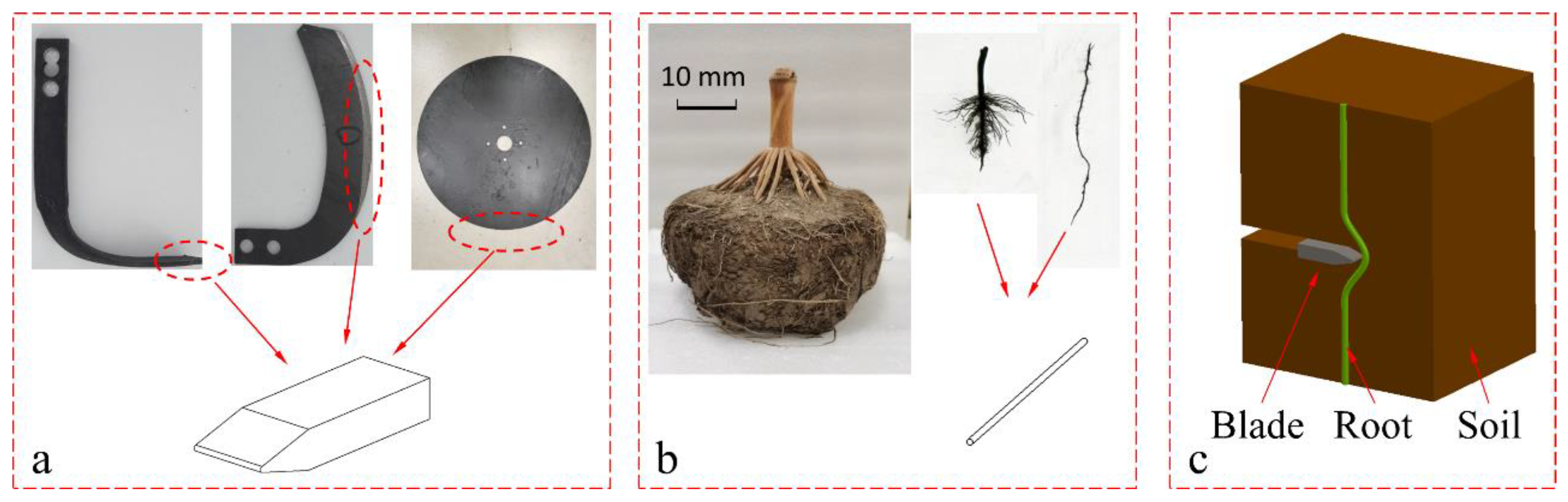
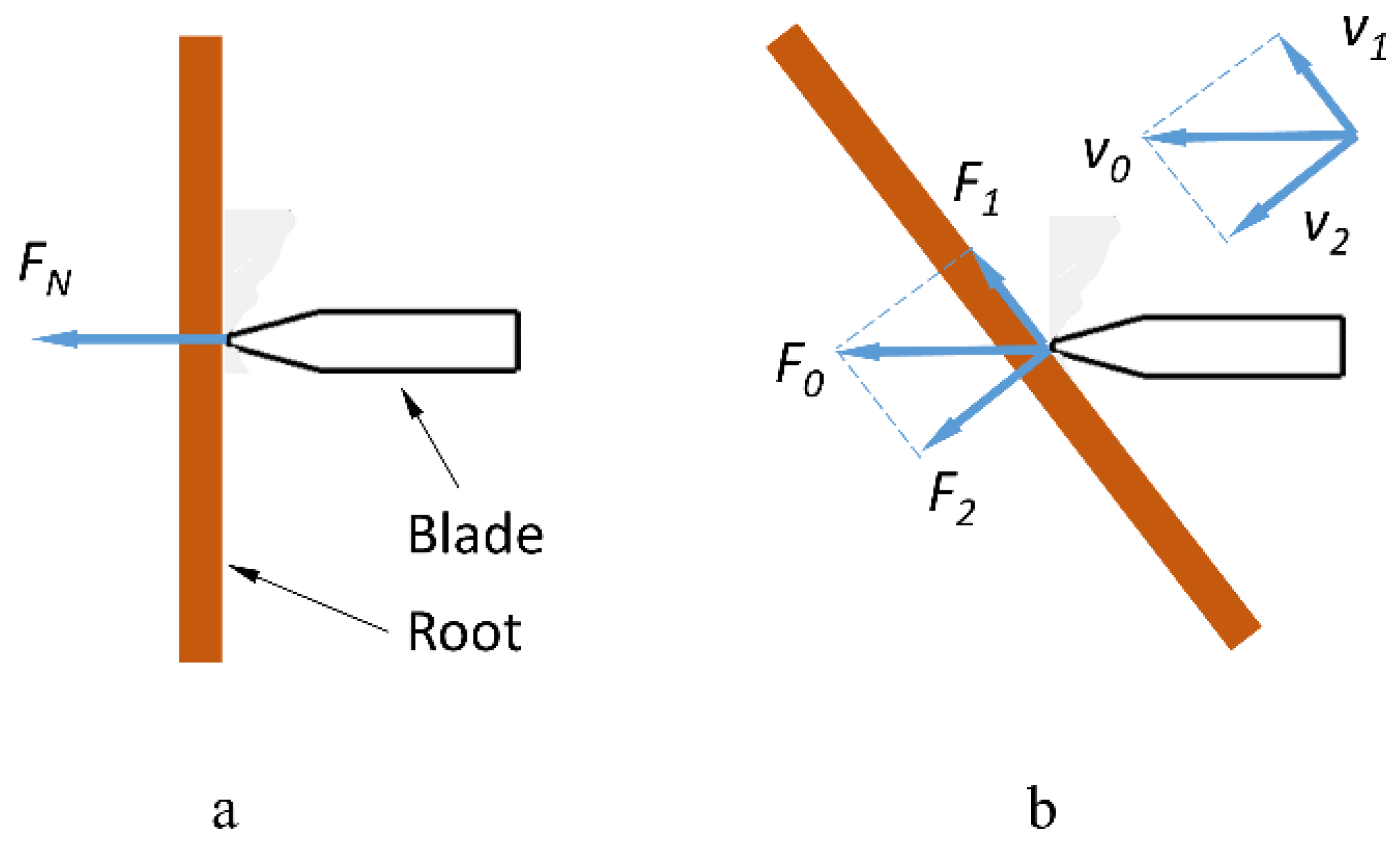
2.1. Simplified Method of the Experiment

Equipment for rotary tillage and no-till seeding possesses stubble-breaking functions. The common cutting components in these devices can be considered as flat cutting blades at limited cutting distances [10,11] (Figure 1a). To eliminate the influence of uncertain factors on the experiment, it is necessary to exclude the influence of complex root structures and impurities on the experiment. To exclude the influence of complex root structures on the experiment, according to previous research, it is possible to start the study from the mechanical properties of a single root–soil composite [18,21] and then analyze the influence of the relative position between the blade and the typical structure of roots on the cutting [15,22,23]. In turn, the influence of the typical structure of roots on the interaction between the blade and the root–soil composite can then be obtained. To eliminate the influence of impurities in the soil on the experiment without losing generality, according to the research of Zhang et al. [16], it is necessary to sieve and remold the soil to make root–soil composites (Figure 1c). In addition, to eliminate the interference of boundary effects on the experiment, the size of the remolded root–soil composite needs to be sufficiently large, and the results need to be judged to exclude abnormal force changes caused by the boundary [24]. Schwarz et al. [25] found that damage to the root–soil composite depended on the interaction between soil deformation and the geometrical and mechanical properties of the roots. Therefore, it is necessary to conduct a comparative study of root deformation and blade-cutting force. To verify the results of the cutting experiment on remolded root–soil composites and promote the conclusions obtained, it is necessary to conduct cutting experiments on maize root–soil composites [10,11]. However, since the entire cutting process is invisible, it is necessary to perform X-ray computed tomography (CT) scanning on the maize root–soil composite before the cutting experiment [26,27]. It can help evaluate root deformation by comparing the original position of the roots with the position of the roots on the cut surface.

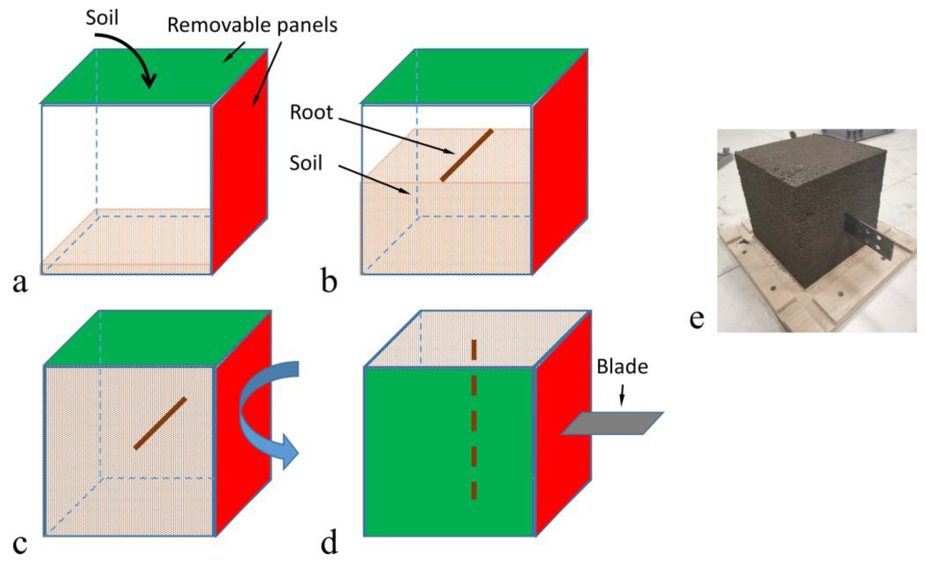
2.2. Sample Preparation

The maize stubble, soil, and roots used in the experiment were collected on 28 October 2023 from the Jilin University Agricultural Experimental Base in Changchun City, Jilin Province. The maize variety was Zhengdan 958, with roots mainly distributed in the soil layer at a depth of 0–100 mm. The maize stubbles used in the experiment had an average stem diameter of 25 mm and a collection size of 200 mm × 200 mm × 200 mm for the underground parts. The root density was 128 kg/m3, and the wet base moisture content ranged from 78.78% to 85.60%. The soil was black loam, with an average soil compaction of 1.12 MPa in farmland. The wet base moisture content ranged from 18.7% to 20.3%. The soil was naturally air-dried and crushed first, and then a 3 mm sieve was used to prepare the soil with a moisture content of 19% for later use, ensuring that moisture content did not fluctuate more than 0.5%.
Based on previous research [10,11,28], the remolded root–soil composite was made into a 200 mm × 200 mm × 200 mm cubic sample by adding and compacting the soil in four layers. By controlling the weight and volume of the soil, it could be ensured that the compaction of each layer of soil was consistent. A detachable shear box with an inner cavity size of 200 mm × 200 mm × 200 mm was used to prepare remolded root–soil composites, and the top and side plates of the shear box were disassembled to fill and remove the samples. The sample preparation process is shown in Figure 2:
  • Remove the green plate of the box, fill the box with the soil in four batches, and compact the soil to the specified compaction (Figure 2a);
  • Place the root on the surface of the second layer of the compacted soil (Figure 2b);
  • Remove the red plate, install the green plate, and rotate the box 90° (Figure 2c);
  • Adjust the blade plane to be perpendicular to the root (Figure 2d).
To mitigate boundary effects, the roots should be positioned as far away from the side plate as possible. The maize root–soil composite was pruned and vertically positioned within a cutting box.
The cutting experiments were conducted on the remolded and undisturbed maize root–soil composite on a cutting bench (Figure 3a). The bench mainly comprised a frame, a servo cylinder (Guangzhou Hezhicheng Metal Products Co., Ltd., Guangzhou, Guangdong, China, maximum thrust: 500 N, power: 400 W), a force sensor (Bengbu Dayang Sensing System Engineering Co., Ltd., Bengbu, Anhui, China, range: 0–50 kg), and a computer. There were linear sliding rails installed on the bench. The servo-electric cylinder with adjustable speed was positioned at one end of the bench, while the root–soil composite was placed in the box at the opposite end. The servo-electric cylinder propelled the blade, affixed to the force sensor, to cut into the remolded root–soil composites along the linear sliding rail. The real-time force data were output from the computer. The experiments stopped when the blade reached a depth of 180 mm into the soil. The blade sizes were 250 mm × 40 mm × 4 mm, made from 65 Mn with a 30° blade edge.
To obtain the original position coordinates of the roots before the cutting experiments, a NeuViz 128 CT scanner (Neusoft Medical Systems Co., Ltd, Shenyang, Liaoning, China) was used to obtain high-resolution scanning images of the root–soil composite. In total, 629 CT slices, each with a thickness of 0.5 mm, were generated through X-ray CT scanning, using voltages ranging from 80 to 140 kW and automatic current ranging from 20 to 500 mA.

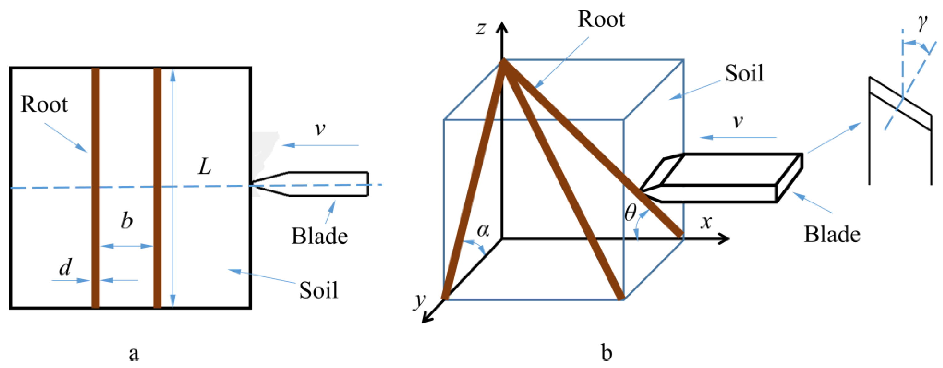
2.3. Experiment Method

To investigate the influence of key factors on the interaction between blades and root–soil composites, it is necessary to investigate the mechanical properties of roots, soil, and root–soil interfaces, as well as the structure of roots and the operating parameter of the blade. Because the shear strength of the root is related to its diameter [29] and the root–soil interface force is related to its length [4], the root diameter (d) and length (L) were selected as experimental factors (Figure 4a). The distance between the two endpoints of a root was defined as the root length, and the diameter at the midpoint of the root was defined as the root diameter. A typical root structure includes the number of roots per unit of volume and spatial distribution angles (Figure 4a,b). The more roots there are in the unit volume of the root–soil composite, the closer the distance between roots, so the distance (b) between neighboring roots can be selected for analysis (Figure 4a). The blade slide-cutting angle (γ) was defined as the angle between the cutting speed direction of a certain point on the blade and the normal direction of that point [22,30] (Figure 4b).
To investigate the effect of complex and randomly distributed maize roots on cutting, according to the simplified method in Section 2.1, it was assumed that the blade had a fixed position and motion trajectory during the cutting process, and the relative position between the blade and the root could be determined by the bevel and oblique angles [22,23,31]. The positions of the root and blade in the Cartesian coordinate system can be defined as shown in Figure 4b. The blade moved in the negative direction along the x-axis, and its motion trajectory was located in the x–y plane. The bevel angle α was defined as the angle between the plane where the blade was located and the root axis within the z–y plane (Figure 4b). The oblique angle θ was defined as the angle between the plane where the blade was located and the root axis within the z–x plane (Figure 4b). Through measurement, both the bevel angle and oblique angle were distributed within the range of 30° to 150°. There was symmetry in the distribution angle, so the levels of the two angles were set within the range of 30° to 90°. The cutting experiment conducted on remolded root–soil composites was a single-factor experiment, and each experimental group was conducted five times. The factors and levels related to the root–soil composite characteristics parameters are presented in Table 1, while those concerning blades are shown in Table 2. During the experiment, real-time force data were collected. After the experiment, the third and fourth layers of soil were carefully removed with a brush, so that the roots embedded in the soil were exposed and not disturbed. The dragging distance of the root was determined by the displacement of the contact point between the blade and the root. The control group of the experiment had a soil compaction of 1 MPa, a root length of 150 mm, a root diameter of 2.5 mm, a blade bevel angle of 90°, a blade oblique angle of 90°, a sliding-cutting angle of 0°, and a cutting speed of 100 mm/s.
The cutting experiment of the maize root–soil composite referred to previous experimental methods [10,11]. The cutting experiments used a blade to conduct longitudinal cutting experiments on maize root–soil composites at cutting positions (I, II, III) 30 mm, 60 mm, and 90 mm away from the maize stem axis (Figure 5a). The force data of the blade was output by the computer. Excess soil and roots were removed after the experiments, and the cross-sectional shape was observed. For convenience, the direction of blade movement was set as the z-axis, and the direction perpendicular to the blade surface was set as the x-axis, aligning the z-axis with the stem axis (Figure 5b). The position of the root was marked on the cutting surface on the z–x coordinate system to determine its position.
To determine the root’s original distribution characteristics of the maize root–soil composite, CT scanning must be conducted before the cutting experiment to acquire slice images (Figure 5c). For convenience of observation and analysis, the root–soil composite was horizontally positioned on the CT scanning base during scanning. The threshold segmentation method enabled rapid acquisition of root position on the cutting surface. The root position was extracted from CT images and labeled on the z–x coordinate system to determine the roots’ original coordinate parameters in the uncut root–soil composite.

3. Results

To reveal the interaction mechanisms between blades and root–soil composites, the cutting process of remolded root–soil composites was first analyzed. Then, the influence of key parameters of root–soil composites and cutting parameters of the blade was investigated. Finally, the above conclusion was validated by cutting maize root–soil composites.

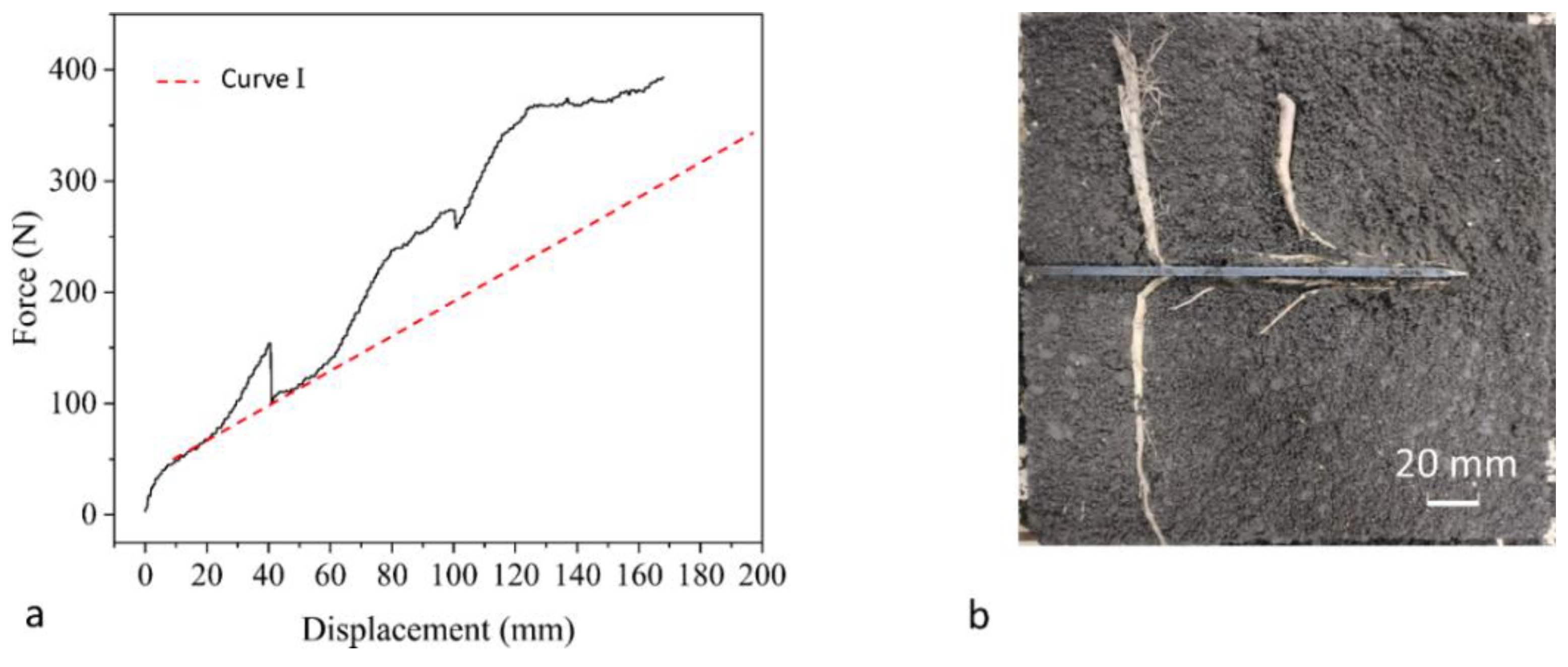
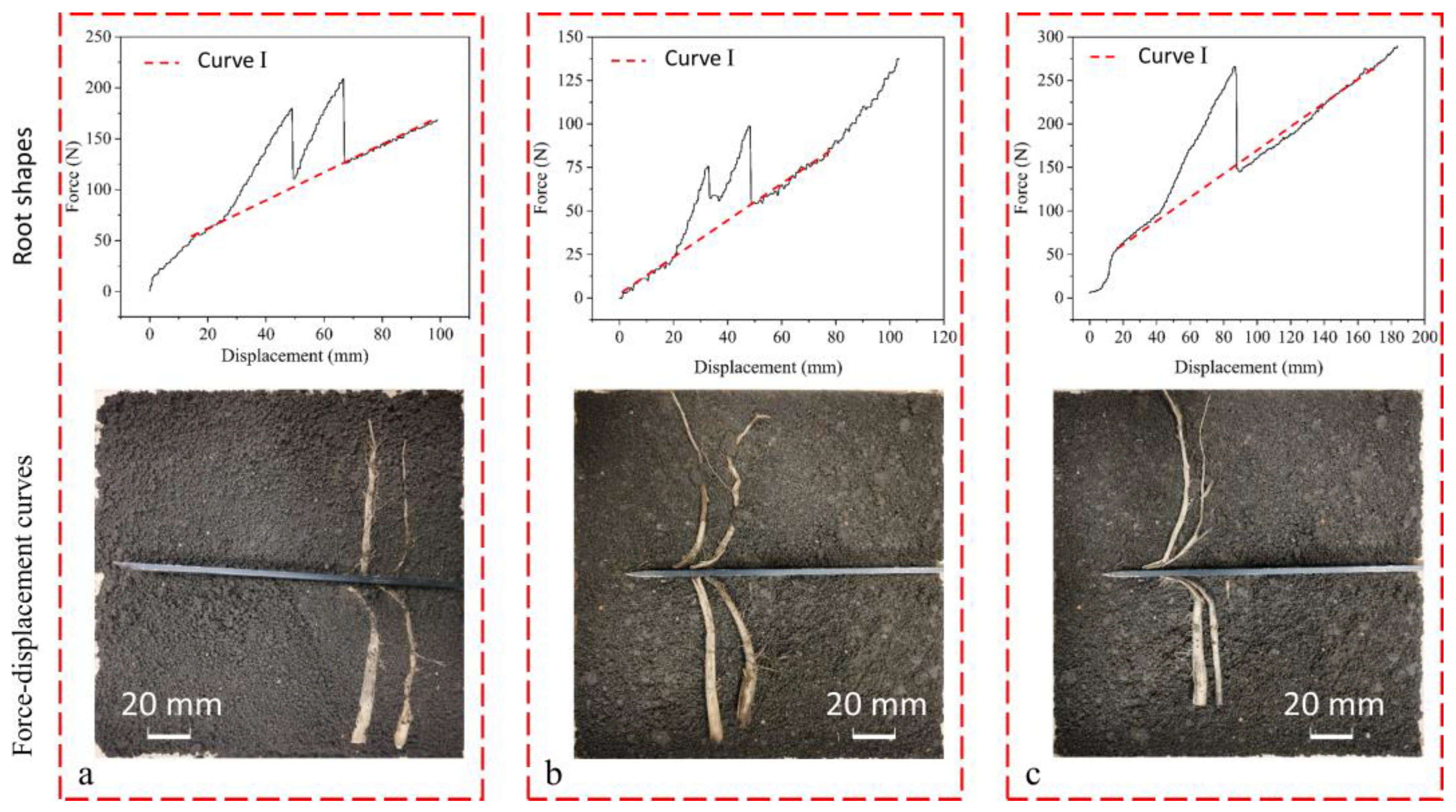
3.1. Process of Cutting Remolded Root–Soil Composites

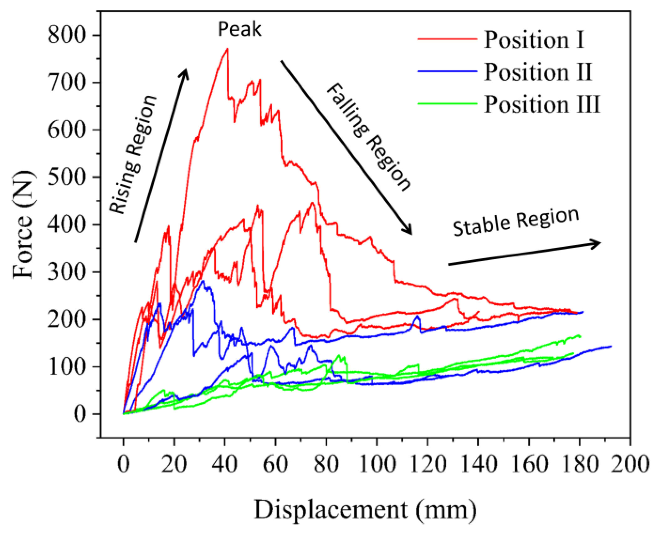
3.1.1. Root-Cutting Force

As shown in Figure 6a, the curves with peaks from left to right represent the force–displacement curves of the root–soil composite with root diameters of 2.48 mm, 2.5 mm, and 3 mm, respectively. s is the distance the blade moved from contact to cut the root off (Figure 6a). F is the additional force exerted by the blade on the soil due to the presence of roots, referred to as the root-cutting force (Figure 6a). Overall, there was no significant fluctuation in the force–displacement curve, suggesting that the influence of boundary conditions on the experiment was weak. This curve showed clear rising and falling regions and obvious peaks, consistent with phenomena observed in a lot of research [10,11]. As the blade cut into the soil at a constant speed, the curve exhibited a linear growth trend (Curve I) with a low slope; when the blade contacted the root, the slope of the curve gradually increased, showing an upward trend in the power function (Region I), which is consistent with the phenomenon discovered by Xu et al. [18]. In the rising stage of the curve, two different situations are worth noting: when cutting the root–soil composites with root diameters of 2.48 mm and 2.5 mm, the curve showed a linear growth trend and a high slope; when cutting the root–soil composite with a root diameter of 3 mm, the rising stage of the curve was divided into two segments. The slope of the curve in Region II was higher, while the slope of the curve in Region IV gradually decreased; when the curve reached its peak (Region III) and two noticeable breaking sounds were heard, the roots with diameters of 2.48 mm and 2.5 mm broke, causing the curve to suddenly drop and then steadily rise along Curve I. When cutting a root–soil composite with a root diameter of 3 mm, the curve did not suddenly drop (Region Ⅴ) and instead floated above Curve I.
Curve I increased linearly and could be explained using the pure cutting theory [32]:
P x = 2 K 1 S 1 s i n ( α 2 ) + 2 K 1 S 1 μ k s c o s ( α 2 ) + 2 K 2 S 2 μ k s
P z = 2 K 1 S 1 c o s ( α 2 ) + 2 K 2 S 2 μ k s s i n ( α 2 )
where S1 and S2, respectively, represent the surface areas of the blade’s side edge and cutting edge in contact with the soil, mm2; K1 and K2 are the deformation ratios of the soil at the blade’s side edge and cutting edge, respectively; α is the blade’s cutting angle, °; and μks is the dynamic friction coefficient between the root and the soil.
As the only variable in the cutting process is the surface area of the blade’s side edge, and this contact area varies linearly with displacement, the force–displacement curve coincided with Curve I. When the blade contacted the root, the curve showed a high slope and peak, indicating that the presence of the root strengthened the soil in resisting external forces. This phenomenon is consistent with the findings of Wu et al. [21,33].
In summary, due to the presence of roots, the force–displacement curve was significantly affected, indicating that the soil was strengthened. To delve deeper into this phenomenon, conducting a comparative analysis of the relationship between root deformation and the force–displacement curves was necessary.

3.1.2. Root Deformation

The shape of the root with diameters of 2.48 mm, 2.5 mm, and 3 mm after being cut from left to right is shown in Figure 6b. The root fractured at the contact point between the blade and the root. The distance between the fracture point and the initial point was the dragging distance (Figure 6b). After measurement, it was found that the total length of the cut root was greater than the original length, indicating that the root was tensioned and elongated. Wu et al. [21,33] found that the combination of soil, roots, and binders forms a reinforced soil matrix in which stress is transmitted from the soil to the roots, causing root elongation and thereby increasing the overall strength of the matrix. Therefore, the soil transformed the destructive effect of blades into the tensile force of the roots through the root–soil interface, thereby improving the strength of root–soil composites and increasing the force of blades. It also indicated that the tensile force of the root is an important component of the root-cutting force.
It could be observed that the roots supported by the soil were tensioned under the action of the blade (Figure 6b), and simultaneously, the soil deformed under the compression of the roots. Root deflection was greater at the point closest to the cutting point, and the length of the root in the deformation area on both sides of the blade was the same (Figure 6b). According to the research of Wu et al. [21,33], the effect of soil on roots could be described by the elastic foundation beam model. Due to lesser root deformation before the root fracture, the finite length of roots can be approximated as a beam element wrapped in elastic soil using the elastic foundation beam model and the equilibrium equation of an elastic foundation beam to analyze the stress on the root, as described in the following equations [34]:
d F = d k d y
E I d 4 y d x 4 + d k d y = 0
where F is the foundation reaction force of the soil, N; k is the foundation modulus of the soil, N/mm3; d is the diameter of the root, mm; y is the deflection of the root, mm; E is the elastic modulus of the root, N/mm2; and I is the moment of inertia of the root, kg/mm2.
The force acting on the root from the soil is borne by the blade [18,19], indicating that the soil foundation reaction force is an important component of the root-cutting force. According to Equation (3), the soil reaction force is directly proportional to root deflection, and the root tensile force is also approximately directly proportional to root strain [12]. Thus, the curve in Region II was linear. After the root fractured, the blade continued to cut the soil, therefore the curve returned to Curve I (Figure 6a).

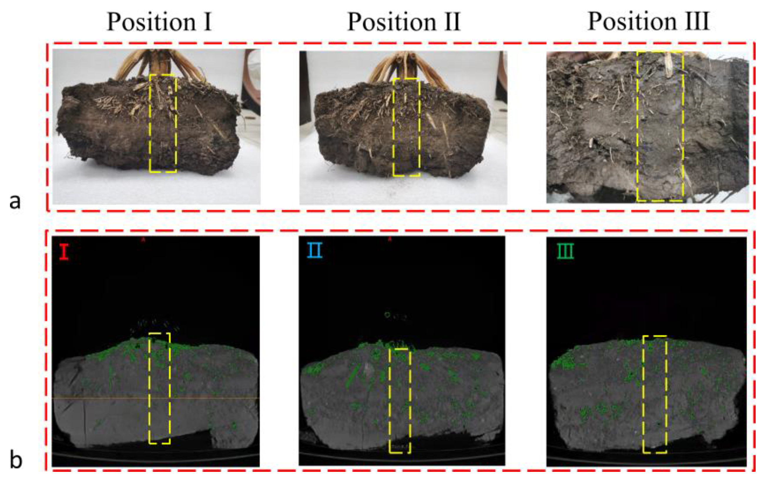
3.1.3. Failure of the Root–Soil Interface

As shown in Figure 6b, for the root–soil composites with root diameters of 2.48 mm and 2.5 mm, the two ends of the roots did not leave their initial positions, indicating that the roots were anchored well. For the root–soil composite with a diameter of 3 mm, the two ends of the root moved from their initial positions, indicating that the root was dragged. When the axial tension of the root exceeded the critical interaction force between the root and soil, the root–soil interface failed and the root was dragged away by the blade (Figure 6b). The interaction force between roots and soil can be calculated using the following equation [4]:
F r s = E i π d L 2
where Ei is the axial interface friction coefficient, N/mm3, and L is the length of the root, mm.
According to the conclusion in Section 3.1.1 and Section 3.1.2, F mainly originated from soil foundation reaction force and root tensile force. Due to the loss of root tensile force on the dragged roots, the slope of the curve in Region IV decreased significantly. The root attached to the blade, causing the blade’s cutting edge to fail. Therefore, the force–displacement curve of the blade in Region V was significantly higher than Curve I. If the strengthening effect of roots on soil is to be fully utilized, or if there are blades that can effectively cut and avoid dragging the roots, the following critical criterion must be met:
F r s > T
where T is the axial tensile force of the root.
In summary, when cutting root–soil composites, root dragging should be avoided to prevent higher resistance and energy consumption caused by the blade’s cutting edge failure. This conclusion can explain Tamas’ previously unexplained findings [35]. Tamas used the discrete element method to simulate the cutting of root–soil composites with sweep tools and he found that the resistance in cases where the roots fractured was greater than that in cases where the roots did not fracture. The root that fractured met the critical conditions mentioned above. Broken roots can fully exert their strengthening effect on the soil, allowing the cutting force to reach its maximum value; conversely, unbroken roots and roots that do not meet critical conditions describe the same cutting process. Dragged roots make the blade’s cutting edge fail, resulting in higher resistance than when cutting the soil.

3.2. Effect of Key Parameters of Root–Soil Composites on Cutting

3.2.1. Effect of Soil Compaction on Cutting

Figure 7a illustrates the effect of varying soil compaction on root-cutting force and dragging distance. Under the same conditions, the effect of soil compaction on the root-cutting force was not significant (p > 0.01); however, the dragging distance was inversely proportional to soil compaction. When soil compaction increased from 1 to 1.5 MPa, the dragging distance decreased by 6.74 mm.
Higher soil compaction has a better supportive effect on roots, and the soil foundation modulus increases with soil compaction. According to Equation (3), soil foundation reaction forces increase with an increasing soil foundation modulus. Higher soil reaction forces acting on roots make them more susceptible to fractures at shorter dragging distances, thus avoiding debonding of the root–soil interface (Section 3.1.3). However, the stubble-breaking device will face greater resistance and impact under higher soil compaction conditions, which will affect the stability and service life of the stubble-breaking device [14,36]. Therefore, a shock-absorption and drag-reduction design should be implemented on the stubble-breaking device when conducting stubble-breaking operations in farmlands with higher soil compaction. In summary, avoiding the debonding of root and soil contradicts reducing the resistance of the blade. Therefore, it is crucial to choose suitable soil conditions for stubble-breaking operations.

3.2.2. Effect of the Root Diameter on Cutting

Figure 7b illustrates the effect of varying root diameter on root-cutting force and dragging distance. The root-cutting force and dragging distance increased as the diameters of the roots increased. Compared with those of the root–soil composite with a root diameter of 2 mm, the root-cutting force of the root–soil composite with a root diameter of 3 mm increased by 46.94%, and the dragging distance increased by 12.93 mm.
These results indicate that the diameter and the shear strength of the root significantly impacted the strength of the root–soil composite. The roots with greater diameters had a significant impact on the mechanical properties of root–soil composites. Zheng et al. and Zhao et al. [10,11] also obtained the same conclusion in studying the mechanical properties of root–soil composites. Maize roots, which have thick diameters, are generally distributed in the cultivated layer 0–100 mm away from the ground. The roots are more densely distributed closer to the stem at the cutting position [10,11]. According to Equation (3), the growth rate of the soil foundation reaction force acting on the root is related to the root diameter and soil foundation modulus. As root diameters increase, the slope of the force–displacement curves and the peak of the root-cutting force increase. Consequently, cutting thicker root–soil composites will encounter higher resistance and impact. Bai et al. and Jia et al. [36,37] found the same phenomenon in measuring the resistance and torque of stubble-breaking operations.

3.2.3. Effect of the Root–Soil Interface Force on Cutting

The force–displacement curves and root shapes of the root–soil composite with root lengths of 200 mm, 180 mm, and 160 mm are shown in Figure 8a,b, respectively. The root with a length of 200 mm was firmly fixed, making it easier to cut. The roots with shorter lengths were dragged. The force–displacement curve of the fixed root had a clear peak, while the dragged roots not only had no clear peak but also made the blades face greater forces.
According to Equation (5), as the length of the root decreases, the bonding force between the root and soil decreases, making roots with lengths of 180 mm and 160 mm easier to drag. Dragged roots cause the blade cutting edge to fail, which not only prevents the next root from being cut in time and increases drag risks (Figure 8b) but also generates greater cutting force (Figure 8a). This is one of the main reasons for the high resistance generated by the stubble-breaking device. Therefore, ensuring that roots are not dragged is one of the necessary conditions for implementing efficient stubble-breaking operations. Environmental factors such as soil moisture content affect the root–soil interaction force [38,39]. Therefore, it is necessary to carry out stubble-breaking operations under suitable soil conditions to avoid root dragging.

3.2.4. Effect of the Distance between Neighboring Roots on Cutting

Figure 9 shows the root shapes and force–displacement curves when distances between neighboring roots were 5 mm, 10 mm, and 20 mm, respectively. When the distance between the roots was 20 mm, the curve showed two independent unimodal curves (Figure 9a). When the distance between the roots was 10 mm, the two “unimodal” curves overlapped, forming a “bimodal” curve (Figure 9b), but the peaks did not affect each other. When the distance between the roots was 5 mm, the two “unimodal” curves completely overlapped to form a unimodal curve with a higher peak (Figure 9c).
When the distance between neighboring roots is small enough, the root-cutting force superposes, resulting in a higher peak of root-cutting force. Therefore, under the same conditions, within the dragging distance of a root, the superposition effect of root-cutting force becomes more significant as the number of distributed roots increases. That is to say, cutting root–soil composites with a denser root distribution results in a greater root-cutting force. This finding is consistent with the conclusions drawn by Zheng, Sang et al. [10,40]. Therefore, the superimposed effect of root-cutting force is one of the reasons for high resistance and high torque in stubble-breaking operations. Due to the influence of the environment, the distribution of naturally growing roots is complex and random, resulting in irregular vibrations and impacts during the operation of the stubble-breaking device and significantly affecting the quality and stability of the operation. Consequently, a denser root distribution should be avoided along the cutting path.

3.3. Effect of Blade Cutting Parameters on Cutting

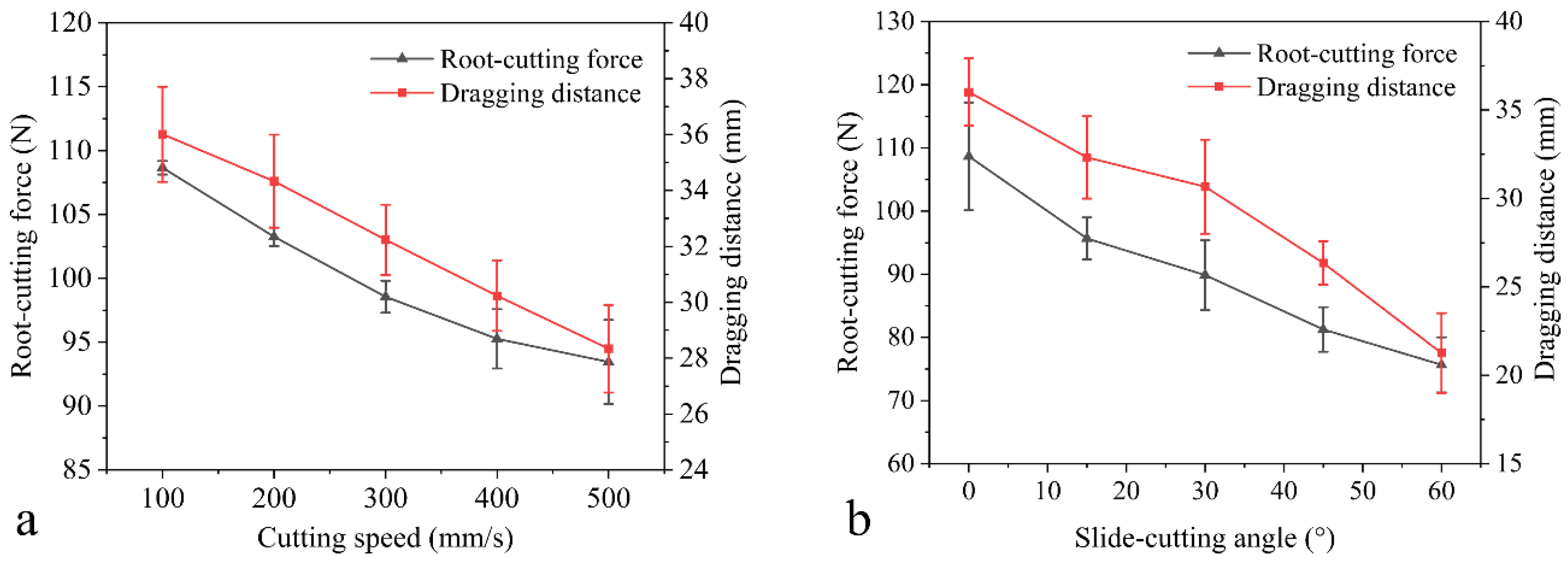
3.3.1. Effect of the Slide-Cutting Angle on Cutting

As shown in Figure 10a, as the slide-cutting angle of the blade increased, the root-cutting force and dragging distance decreased. Compared to those when blade had a slide-cutting angle of 0°, the root-cutting force was reduced by 30% and the root dragging distance was shortened by 14.76 mm when the slide-cutting angle was 60°. This trend is consistent with the changes in the ultimate shear force of cut rice and maize root–soil composites reported by Zheng et al. and Zhao et al. [10,11].
An increase in the slide-cutting angle decreased the actual blade wedge angle, and a sharper blade could cut materials with a lower normal root-cutting force, reducing the root-cutting force [41]. Therefore, the root-cutting force decreased with an increase in the slide-cutting angle. However, as the root-cutting force decreased, the pure-cutting force increased due to the larger contact area between the blade wedge edge and the soil, which is not conducive to reducing resistance and energy consumption (Section 3.1.1). Due to the significant influence of environmental factors on the mechanical properties of root–soil composites [38,39], an optimal slide-cutting angle exists in a certain environment to minimize the root-cutting force. This is one reason for the differences in optimizing blade slide-cutting angles in different studies. Additionally, due to the shorter dragging distance, the superposition effect of root-cutting forces was weakened. Thus, cutting root–soil composites with a dense root distribution using blades with larger slide-cutting angles results in lower resistance. This is consistent with the research findings of Zhao et al. and Zheng et al. [10,11].

3.3.2. Effect of the Cutting Speed on Cutting

As shown in Figure 10b, both root-cutting force and dragging distance decreased with an increasing cutting speed and reached the minimum values at 500 mm/min. Compared to those at a cutting speed of 100 mm/min, the root-cutting force was reduced by 14% and the dragging distance was shortened by 7.67 mm at 500 mm/min.
Dowgiallo et al. [42] found that the transmission time of extrusion deformation of agricultural materials decreased with increased cutting speed, leading to a decrease in local deformation. In the extrusion area, deformation gradually changes from plastic to elastic or brittle. Therefore, increasing the cutting speed helps reduce the cutting force of the root. According to the conclusion in Section 3.2.2, roots with lower shear strength have a lower root-cutting force. Consequently, a higher cutting speed helps reduce the root-cutting force. Subrata et al. [43] found that the pressure rate on tools increases with compression speed when using tools to compress soil. Roots dragged by the blade compress the soil. Thus, as the cutting speed increases, the soil foundation modulus increases. According to the conclusion in Section 3.1, the contact force on the root increases when the soil foundation modulus increases, making the root easier to fracture. Therefore, increasing the cutting speed helps reduce the root-cutting force and dragging distance, thereby avoiding root dragging. However, the pure-cutting force increases with the cutting speed. Therefore, an optimal cutting speed exists to minimize the resistance of cutting root–soil composites. The results from cutting the root–soil composite are not entirely consistent with the influence of cutting speed on cutting crop materials, as summarized in previous studies on other crop materials [30,44,45,46]. Due to the different mechanical properties of soil and roots during high-speed cutting, root–soil composite materials have unique cutting characteristics, resulting in these differences.

3.3.3. Effect of the Bevel Angle on Cutting

As shown in Figure 11a, as the bevel angle decreased, the root-cutting force and dragging distance first decreased and then increased. The blade with a 45° bevel angle had the lowest root-cutting force and shortest dragging distance. Compared to a cutting angle of 90°, the blade with a 45° bevel angle reduced the root-cutting force by 60.47% and the dragging distance by 22.33 mm.
Ghahraei et al. [47] found that increasing the angle between the blade and stem positively affected reducing the cutting force and energy. When the bevel angle was 90°, only positive pressure acted on the root. When the bevel angle was not 90°, both friction and positive pressure acted on the root (Figure 12). At the same dragging distance, the root was subjected to a higher contact force. According to the Hertz contact model [48], a larger contact force makes the roots more prone to fracture. Therefore, cutting the root–soil composite at the optimal bevel angle is beneficial for root fractures, eliminating the root-strengthening effect and reducing the root-cutting force. In summary, using appropriate bevel angles for stubble-breaking operations reduces resistance and avoids root dragging. Therefore, determining the optimal bevel angle for cutting root–soil composites is essential for stubble-breaking operations.

3.3.4. Effect of the Oblique Angle on Cutting

As shown in Figure 11b, as the oblique angle decreased, the root-cutting force and dragging distance decreased. When the oblique angle reached 45°, the root-cutting force and dragging distance reached their minimum values. Compared to a 90° oblique angle, a 45° oblique angle reduced the root-cutting force by 15.12% and shortened the dragging distance by 8.76 mm.
Research has shown that the fibers of maize roots are arranged along the root axis like maize stems, and longitudinal tensile strength is greater than transverse tensile strength [31,49]. Therefore, when the oblique cutting angle was 0°, it was necessary to overcome the longitudinal tensile strength of the root, resulting in higher root-cutting force and dragging distance. As the oblique angle increased, the root tensile force gradually decreased, thus the root-cutting force gradually decreased. When the oblique angle was less than 45°, the contact area between the blade and the root significantly increased. Therefore, when the oblique cutting angle was 30°, the root-cutting force increased. This is consistent with previous research [31]. In summary, using a suitable oblique angle is beneficial for reducing resistance and avoiding root dragging during stubble breaking. Therefore, determining the optimal oblique angle for cutting root–soil composites is essential for designing high-performance stubble-breaking devices.

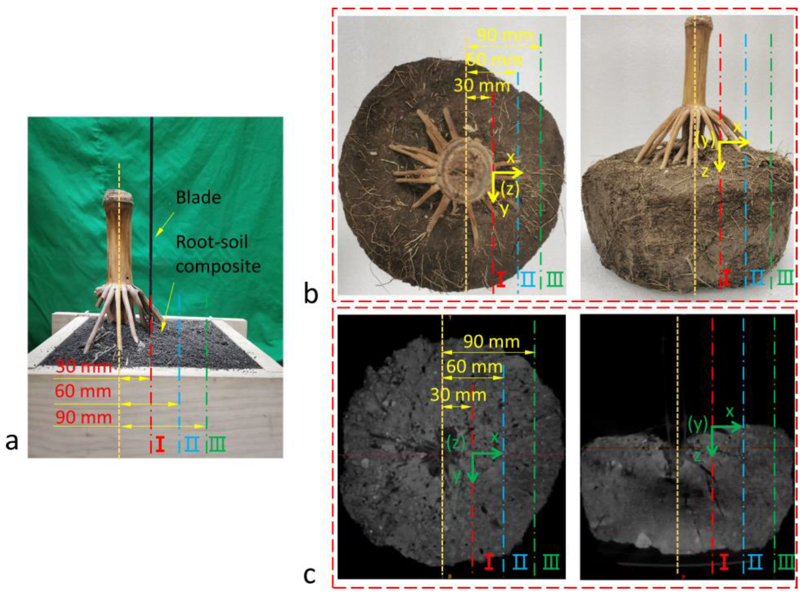
3.4. Process of Cutting Maize Root–Soil Composites

As shown in Figure 13, at different cutting positions (I, II, III) on three maize root–soil composites, the force–displacement curves had rising regions, falling regions, and stable regions, as well as obvious peaks. The rising regions showed a non-linear growth trend, accompanied by irregular drops and local peaks. At the cutting positions closer to the stem, the overall slope of the curves rose faster, and the peaks were higher. When the curve entered the falling regions, irregular descent and rebound with local peaks were displayed. When the curve reached the stable region, the curve of the cutting position further away from the stem experienced a continuous and stable increase, while the cutting position closer to the stem experienced a higher force. Figure 14a shows the cutting surface of the maize root–soil composite. It can be observed that cut roots were exposed on the cutting surface. Notably, the roots were more densely distributed at cutting positions closer to the stem. Some roots were cut off and buried in the soil, while others were separated from the soil and displaced without cutting.
The coordinates of the cut roots and the original coordinates of the roots were annotated using cross-sectional images (Figure 14a) and CT images (Figure 14b), respectively. The original coordinates of the roots, the coordinates of the cut roots, and force–displacement curves were combined in one graph (Figure 15) to compare and analyze the relationship between root deformation and blade force. The areas marked with green and red circles in Figure 15 represent the coordinates of roots before and after cutting, respectively. It can be observed that due to the presence of maize roots, the soil was strengthened and the blade force was significantly increased (Section 3.1.1). The maize roots, especially the primary roots, were denser closer to the stem. Therefore, in the rising region, the curve rose faster and had higher peaks. This is consistent with the results of Section 3.2.2 and Zheng’s research [10]. Notably, the distribution characteristics of maize roots significantly affected the cutting force. The region with a dense root distribution was also the region where the force–displacement curve fluctuated most frequently, with most local peaks occurring in this area. This was because maize roots that grew naturally were not evenly distributed in the soil, leading to irregular drops and rebounds with local peaks during the root-cutting process. By comparison, the contact sequence between the blade and the root was precisely related to changes in the slope of the curve. Whenever the blade began to contact the root, the slope of the curve significantly increased. When the root fractured, the curve suddenly dropped. The starting position of a peak was consistent with the original coordinates of the roots. However, it is worth noting that the coordinates where the peak appeared were not consistent with the coordinates of the cut root. It can be observed that the cut roots all moved along the cutting direction, indicating that the hysteresis of the peak was caused by the drag of the roots. Compared to cutting a single root–soil composite, there was a higher peak when cutting the maize root–soil composite. This was because when multiple roots contacted the blade, force accumulated, and the force superposition effect described in Section 3.2.4 occurred, resulting in a significant increase in force. After the curve entered the stable region, under the action of pure cutting force, the curve steadily rose. However, the influence of the densely distributed roots in the soil made the soil and roots tightly adhere to the blade, and the dragged roots were attached to the blade, causing the blade cutting edge to fail (Section 3.2.3). Therefore, at cutting positions closer to the stem, the force in the stable region of the curve was higher.

4. Conclusions

This study revealed the interaction mechanisms between the blades and root–soil composites, providing a theoretical basis for designing high-performance stubble-breaking devices. A simplified experimental method was proposed to conduct cutting tests on remolded root–soil composites and maize root–soil composites, investigating the influence of the key parameter of the root–soil composite and cutting parameters of the blade on cutting. The results indicated that:
(1) The simplified experimental method provided a simple and reliable method for studying the interaction mechanisms between the blades and root–soil composites. By comparing and analyzing the force–displacement curve and root deformation, it was found that the soil transformed the destructive effect of blades into the tensile force of the roots through the root–soil interface, thereby improving the strength of root–soil composites and increasing the resistance of the blades;
(2) The soil support force and the interface force between roots and soil had a significant impact on cutting. Higher soil compaction and root–soil interface forces helped prevent root dragging, but higher soil compaction also helped increase resistance. Due to the correlation between the mechanical parameters of these root–soil complexes and soil conditions, there could exist the most suitable soil conditions for stubble-breaking operations. In the case of a dense root distribution in root–soil composites, or when cutting multiple roots simultaneously, the superposition and accumulation effects of resistance became more pronounced. Therefore, it was necessary to avoid a dense distribution of roots along the cutting path and blade edge to prevent high resistance;
(3) The cutting parameters of the blade had a significant impact on cutting. As the bevel angle and oblique angle increased, the root-cutting force and dragging distance first decreased and then increased. Therefore, using appropriate cutting angles for cutting could effectively reduce resistance; increasing the slide-cutting angle and cutting speed decreased the root-cutting force and dragging distance, although the blade encountered greater pure cutting force;
In future research, combining established theoretical models such as the elastic foundation beam model, the pure cutting model, the Hertz contact model, and the root–soil interface failure criterion will help construct mechanical models of cutting root–soil composites, providing theoretical basis for the design and optimization of cutting devices and promoting the development of more efficient and effective agricultural machinery.

Author Contributions

Conceptualization, X.L.; methodology, X.L.; software, X.L.; validation, X.L.; formal analysis, X.L.; investigation, X.L.; resources, Y.M.; data curation, X.L.; writing—original draft preparation, X.L.; writing—review and editing, X.L., P.G., H.Q., Q.Z., M.G. and Y.M.; visualization, X.L.; supervision, P.G., H.Q., Q.Z., M.G. and Y.M.; project administration, Y.M.; funding acquisition, Y.M. All authors have read and agreed to the published version of the manuscript.

Funding

This work was supported by the National Natural Science Foundation of China (grant number 52275288 and 52105300), the National Key Research and Development Program of China (grant number 2023YFD2000903), and the Jilin Province Science and Technology Development Plan Item (grant number 20210202021NC).

Institutional Review Board Statement

Not applicable.

Data Availability Statement

The data presented in this study are available upon request from the corresponding authors.

Conflicts of Interest

The authors declare no conflicts of interest.

References

  1. Keshavarz Afshar, R.; Cabot, P.; Ippolito, J.A.; Dekamin, M.; Reed, B.; Doyle, H.; Fry, J. Corn Productivity and Soil Characteristic Alterations Following Transition from Conventional to Conservation Tillage. Soil Tillage Res. 2022, 220, 105351. [Google Scholar] [CrossRef]
  2. Rocco, S.; Munkholm, L.J.; Jensen, J.L. Long-Term Soil Quality and C Stock Effects of Tillage and Cover Cropping in a Conservation Agriculture System. Soil Tillage Res. 2024, 241, 106129. [Google Scholar] [CrossRef]
  3. He, J.; Li, H.; Chen, H.; Lu, C.; Wang, Q. Research Progress of Conservation Tillage Technology and Machine. Trans. Chin. Soc. Agric. Mach. 2018, 49, 1–19. [Google Scholar] [CrossRef]
  4. Xie, M. A Study on the Soil Mechanical Role of Tree Roots in the Stability of Slopes. J. Soil Water Conserv. 1990, 4, 7–14. [Google Scholar]
  5. Zhang, S.; Zhao, H.; Wang, X.; Dong, J.; Zhao, P.; Yang, F.; Chen, X.; Liu, F.; Huang, Y. Discrete Element Modeling and Shear Properties of the Maize Stubble-Soil Complex. Comput. Electron. Agric. 2023, 204, 107519. [Google Scholar] [CrossRef]
  6. Zhao, J.; Lu, Y.; Guo, M.; Fu, J.; Wang, Y. Design and Experiment of Bionic Stubble Breaking-Deep Loosening Combined Tillage Machine. Int. J. Agric. Biol. Eng. 2021, 14, 123–134. [Google Scholar] [CrossRef]
  7. Zhu, H.; Wu, X.; Bai, L.; Qian, C.; Zhao, H.; Li, H. Development of the Biaxial Stubble Breaking No-Tillage Device for Rice Stubble Field Based on EDEM-ADAMS Simulation. Trans. Chin. Soc. Agric. Eng. 2022, 38, 10–22. [Google Scholar] [CrossRef]
  8. Lin, J.; Lv, Z.; Li, H.; Wang, X.; Wang, D. Design and Experiment of Passive Anti-Winding Stubble Breaking and Ridge Cleaning Device for No-Tillage Planter. Trans. Chin. Soc. Agric. Mach. 2023, 54, 19–27. [Google Scholar] [CrossRef]
  9. Wang, J.; Zhao, S.; Gao, L.; Yuan, Y.; Yang, Y. Design and Experiment of Passive Disc Cutting Blade in Corn Ridges. Trans. Chin. Soc. Agric. Mach. 2021, 52, 59–67. [Google Scholar] [CrossRef]
  10. Zheng, L.; Luo, X.; Zeng, S.; Wang, Z.; Liu, C.; Qi, X. Shear Characteristics of Rice Root-Soil Composite. Trans. Chin. Soc. Agric. Mach. 2017, 48, 63–71. [Google Scholar] [CrossRef]
  11. Zhao, X.; Zhang, Z.; Huang, Q.; Zhang, G. Cutting Performance of Corn Root-Soil Composite. Trans. Chin. Soc. Agric. Mach. 2013, 44, 126–132. [Google Scholar] [CrossRef]
  12. Li, M.; Xu, S.; Yang, Y.; Guo, L.; Tong, J. A 3D Simulation Model of Corn Stubble Cutting Using Finite Element Method. Soil Tillage Res. 2017, 166, 43–51. [Google Scholar] [CrossRef]
  13. Zou, L.; Yan, D.; Niu, Z.; Yuan, J.; Cheng, H.; Zheng, H. Parametric Analysis and Numerical Optimisation of Spinach Root Vibration Shovel Cutting Using Discrete Element Method. Comput. Electron. Agric. 2023, 212, 108138. [Google Scholar] [CrossRef]
  14. Zhang, S.; Jia, X.; Dong, J.; Wang, X.; Zhao, H.; Chen, X.; Zhang, Z.; Huang, Y.; Shi, J. Optimization of Operating Angles of Disc Coulters for Maize Residue Management Using Discrete Element Method. Comput. Electron. Agric. 2024, 218, 108691. [Google Scholar] [CrossRef]
  15. Yuan-jun, J.; Alam, M.; Li-Jun, S.; Umar, M.; Sadiq, S.; Jia, L.J.; Rahman, M. Effect of Root Orientation on the Strength Characteristics of Loess in Drained and Undrained Triaxial Tests. Eng. Geol. 2022, 296, 106459. [Google Scholar] [CrossRef]
  16. Zhang, C.B.; Chen, L.H.; Liu, Y.P.; Ji, X.D.; Liu, X.P. Triaxial Compression Test of Soil-Root Composites to Evaluate Influence of Roots on Soil Shear Strength. Ecol. Eng. 2010, 36, 19–26. [Google Scholar] [CrossRef]
  17. Ning, P.; Xia, X.; Jiang, Y. An Estimation Model of the Ultimate Shear Strength of Root-Permeated Soil, Fully Considering Interface Bonding. Forests 2023, 14, 819. [Google Scholar] [CrossRef]
  18. Xu, W.; Zhang, L.C. On the Mechanics and Material Removal Mechanisms of Vibration-Assisted Cutting of Unidirectional Fibre-Reinforced Polymer Composites. Int. J. Mach. Tools Manuf. 2014, 80, 1–10. [Google Scholar] [CrossRef]
  19. Xu, W.; Zhang, L. Mechanics of Fibre Deformation and Fracture in Vibration-Assisted Cutting of Unidirectional Fibre-Reinforced Polymer Composites. Int. J. Mach. Tools Manuf. 2016, 103, 40–52. [Google Scholar] [CrossRef]
  20. Voss, R.; Seeholzer, L.; Kuster, F.; Wegener, K. Analytical Force Model for Orthogonal Machining of Unidirectional Carbon Fibre Reinforced Polymers (CFRP) as a Function of the Fibre Orientation. J. Mater. Process. Technol. 2019, 263, 440–469. [Google Scholar] [CrossRef]
  21. Wu, T.H. Study of Soil-Root Interaction. J. Geotech. Eng. 1989, 114, 1351–1375. [Google Scholar] [CrossRef]
  22. Song, S.; Zhou, H.; Jia, Z.; Xu, L.; Zhang, C.; Shi, M.; Hu, G. Effects of Cutting Parameters on the Ultimate Shear Stress and Specific Cutting Energy of Sisal Leaves. Biosyst. Eng. 2022, 218, 189–199. [Google Scholar] [CrossRef]
  23. Wang, Y.; Yang, Y.; Zhao, H.; Liu, B.; Ma, J.; He, Y.; Zhang, Y.; Xu, H. Effects of Cutting Parameters on Cutting of Citrus Fruit Stems. Biosyst. Eng. 2020, 193, 1–11. [Google Scholar] [CrossRef]
  24. Guo, H.; Goldsmith, J.; Delacruz, I.; Tao, M.; Luo, Y.; Koehler, S.A. Semi-Infinite Plates Dragged through Granular Beds. J. Stat. Mech. Theory Exp. 2012, 2012, P07013. [Google Scholar] [CrossRef]
  25. Schwarz, M.; Cohen, D.; Or, D. Root-Soil Mechanical Interactions during Pullout and Failure of Root Bundles. J. Geophys. Res. Earth Surf. 2010, 115, 1–19. [Google Scholar] [CrossRef]
  26. Dhaliwal, J.K.; Kumar, S. 3D-Visualization and Quantification of Soil Porous Structure Using X-ray Micro-Tomography Scanning under Native Pasture and Crop-Livestock Systems. Soil Tillage Res. 2022, 218, 105305. [Google Scholar] [CrossRef]
  27. Hou, L.H.; Gao, W.; van der Bom, F.; Weng, Z.H.; Doolette, C.L.; Maksimenko, A.; Hausermann, D.; Zheng, Y.; Tang, C.; Lombi, E.; et al. Use of X-Ray Tomography for Examining Root Architecture in Soils. Geoderma 2022, 405, 115405. [Google Scholar] [CrossRef]
  28. Bai, H.; Li, R.; Wang, W.; Xie, K.; Wang, X. Investigation on Parameter Calibration Method and Mechanical Properties of Root-Reinforced Soil by DEM. Math. Probl. Eng. 2021, 2021, 6623489. [Google Scholar] [CrossRef]
  29. Liang, T.; Knappett, J.A.; Duckett, N. Modelling the Seismic Performance of Rooted Slopes from Individual Root-Soil Interaction to Global Slope Behaviour. Geotechnique 2015, 65, 995–1009. [Google Scholar] [CrossRef]
  30. Song, S.; Zhou, H.; Xu, L.; Jia, Z.; Hu, G. Cutting Mechanical Properties of Sisal Leaves under Rotary Impact Cutting. Ind. Crops Prod. 2022, 182, 114856. [Google Scholar] [CrossRef]
  31. Igathinathane, C.; Womac, A.R.; Sokhansanj, S. Corn Stalk Orientation Effect on Mechanical Cutting. Biosyst. Eng. 2010, 107, 97–106. [Google Scholar] [CrossRef]
  32. Gill, W.R.; Vanden Berg, G.E. Soil Dynamics in Tillage and Traction, 1st ed.; U.S. Government Printing Office: Washington, DC, USA, 1967.
  33. Wu, T.H.; Watson, A. In Situ Shear Tests of Soil Blocks with Roots. Can. Geotech. J. 1998, 35, 579–590. [Google Scholar] [CrossRef]
  34. Hetenyi, M. Beams on Elastic Foundation Theory with Applications in the Fields of Civil and Mechanical Engineering; The University of Michigan Press: Ann Arborc, MI, USA, 1946. [Google Scholar]
  35. Tamás, K.; Bernon, L. Role of Particle Shape and Plant Roots in the Discrete Element Model of Soil–Sweep Interaction. Biosyst. Eng. 2021, 211, 77–96. [Google Scholar] [CrossRef]
  36. Bai, X.; Lin, J.; Lü, C.; Hu, Y. Analysis and Experiment on Working Performance of Disc Coulter for No-Tillage Seeder. Trans. Chin. Soc. Agric. Eng. 2014, 30, 1–9. [Google Scholar] [CrossRef]
  37. Jia, H.; Guo, M.; Guo, C.; Zheng, J.; Zhang, C.; Zhao, J. Design of Dynamic Bionic Stubble Cutting Device and Optimization Test of Parameters. Trans. Chin. Soc. Agric. Mach. 2018, 49, 103–114. [Google Scholar] [CrossRef]
  38. Saadati, N.; Mosaddeghi, M.R.; Sabzalian, M.R.; Jafari, M. Soil Mechanical Reinforcement by the Fibrous Roots of Selected Rangeland Plants Using a Large Soil-Root Shear Apparatus. Soil Tillage Res. 2023, 234, 105852. [Google Scholar] [CrossRef]
  39. Xiao, X.; Wu, L.; Li, X.; Zhang, H.; Zhou, J. Study on the Shear Strength of Root-Soil Composite and Root Reinforcement Mechanism. Forests 2022, 13, 898. [Google Scholar] [CrossRef]
  40. Sang, H.; He, C.; Bi, Y.; Liu, M.; Wang, X. Evaluation of the Performance of Very Narrow Tines with Different Geometrical Structures for Tilling Natural Grassland. Biosyst. Eng. 2022, 224, 34–48. [Google Scholar] [CrossRef]
  41. Moiceanu, G.; Voicu, P.; Paraschiv, G.; Voicu, G. Behaviour of Miscanthus at Cutting Shear with Straight Knives with Different Edge Angles. Environ. Eng. Manag. J. 2017, 16, 1203–1209. [Google Scholar] [CrossRef]
  42. Dowgiallo, A. Cutting Force of Fibrous Materials. J. Food Eng. 2005, 66, 57–61. [Google Scholar] [CrossRef]
  43. Karmakar, S.; Lal Kushwaha, R. CFD Simulation of Soil Forces on a Flat Tillage Tool. In Proceedings of the 2005 ASAE Annual International Meeting, Tampa, FL, USA, 17–20 July 2005; Volume 0300. [Google Scholar]
  44. Liu, Z.; Wang, T.; Liu, S.; Yan, X.; Zhao, H.; Wu, X.; Zhang, S. Design and Experimental Study of a Bionic Blade for Harvesting the Wild Chrysanthemum Stem. Agriculture 2023, 13, 190. [Google Scholar] [CrossRef]
  45. Aydın, İ.; Arslan, S. Mechanical Properties of Cotton Shoots for Topping. Ind. Crops Prod. 2018, 112, 396–401. [Google Scholar] [CrossRef]
  46. Zhang, C.L.; Chen, L.Q.; Xia, J.F.; Zhang, J.M. Effects of Blade Sliding Cutting Angle and Stem Level on Cutting Energy of Rice Stems. Int. J. Agric. Biol. Eng. 2019, 12, 75–81. [Google Scholar] [CrossRef]
  47. Ghahraei, O.; Ahmad, D.; Khalina, A.; Suryanto, H.; Othman, J. Cutting Tests of Kenaf Stems. Trans. ASABE 2011, 54, 51–56. [Google Scholar] [CrossRef]
  48. Johnson, K.L. Contact Mechanics, 1st ed.; Cambridge University Press: London, UK, 1985. [Google Scholar]
  49. Johnson, P.C.; Clementson, C.L.; Mathanker, S.K.; Grift, T.E.; Hansen, A.C. Cutting Energy Characteristics of Miscanthus x Giganteus Stems with Varying Oblique Angle and Cutting Speed. Biosyst. Eng. 2012, 112, 42–48. [Google Scholar] [CrossRef]
Figure 1. Experimental simplification objects: (a) simplification of different types of cutting tools into simple cutting blades, (b) simplification of root clusters into a single root, and (c) simplification of cutting the root–soil composite with the blade.
Agriculture 14 01179 g001
Figure 2. Sample preparation method for remolded root–soil composites: (a) Fill the box with layered, compacted soil; (b) place the root on the surface of the second layer of compacted soil; (c) remove the red plate, install the green plate, and rotate the box 90°; (d) adjust the blade to be perpendicular to the root; (e) the prepared sample is cut by a blade from one side of the soil (for the convenience of display, the side and top plates have been removed). The red and green plates represent the two detachable plates on the box.
Agriculture 14 01179 g002
Figure 3. Experiment equipment: (a) experimental cutting bench, (b) X-ray computed tomography scanner.
Agriculture 14 01179 g003
Figure 4. Schematic of cutting the root–soil complex: (a) main view and (b) axis side view; v is the cutting speed, b is the gap between two roots, d is the diameter of the root, L is the length of the root, and α and γ represent the bevel and oblique angles of the root, respectively.
Agriculture 14 01179 g004
Figure 5. The cutting experiment and establishment method of the Cartesian coordinate system on the cross-section of a maize root–soil complex: (a) cutting experiments of maize root–soil composites, (b) real photos (left: top view; right: elevation view), and (c) CT slice images (left: top view; right: elevation view). The red, blue, and green dotted lines represent cutting position I, cutting position II, and cutting position III, with distances of 30 mm, 60 mm, and 90 mm from the stem, respectively.
Agriculture 14 01179 g005
Figure 6. (a) Force–displacement curves of cutting root–soil composites: F is the root-cutting force, s is the root dragging distance, Region I is the initial stage of the curve, Regions II and IV are the rising stage of the curve, Region III is the peak of the curve, Region V is the stage where the root is dragged, and Curve I is the line where the blade cut soil. (b) The shape of the root with diameters of 2.48 mm, 2.5 mm, and 3 mm after being cut from left to right.
Agriculture 14 01179 g006
Figure 7. The effect of varying soil and root parameters on the root-cutting force and dragging distance: variation of (a) soil compaction and (b) root diameter.
Agriculture 14 01179 g007
Figure 8. A root–soil composite with root lengths of 200 mm, 180 mm, and 160 mm was cut from left to right: (a) force–displacement curves of the blade and (b) the shape of roots after being cut.
Agriculture 14 01179 g008
Figure 9. Force–displacement curves of cutting root–soil composites, and the shape of the root after being cut, with distances of (a) 20 mm, (b) 10 mm, and (c) 5 mm.
Agriculture 14 01179 g009
Figure 10. The effect of varying cutting parameters on the root-cutting force and dragging distance: variation of (a) blade cutting speed and (b) slide-cutting angle.
Agriculture 14 01179 g010
Figure 11. The effect of varying cutting parameters on the root-cutting force and dragging distance: variation of (a) bevel angle and (b) oblique.
Agriculture 14 01179 g011
Figure 12. Force analysis of the interaction between the blades and roots: (a) bevel angle of 90° and (b) the bevel angle of 45°.
Agriculture 14 01179 g012
Figure 13. Force–displacement curves of blades at different cutting positions on maize stubble.
Agriculture 14 01179 g013
Figure 14. Real photos and CT slice images of maize root–soil composite cross-section: (a) maize profile shape, (b) CT slices of the profile. The images from left to right are the images of cutting positions I, II, and III, respectively. The yellow-dashed box represents the cutting cross-section.
Agriculture 14 01179 g014
Figure 15. Comparison of in situ coordinates, post-cutting coordinates, and force–displacement curves at three cutting sites of roots in different positions.
Agriculture 14 01179 g015
Table 1. Factors and levels of the root–soil composite characteristic parameters.
LevelsFactors
Soil Compaction
W/MPa
Root Length
L/mm
Root Diameter d/mmDistance between Roots b/mm
10.81001.55
211502.510
31.22003.515
Table 2. Factors and levels of the blade operating parameters.
LevelsFactors
Bevel Angle
α/°
Oblique Angle θSlide-Cutting Angle
γ
Cutting Speed
v/(mm/s)
130300100
2454515200
3606030300
4757545400
5909060500
Disclaimer/Publisher’s Note: The statements, opinions and data contained in all publications are solely those of the individual author(s) and contributor(s) and not of MDPI and/or the editor(s). MDPI and/or the editor(s) disclaim responsibility for any injury to people or property resulting from any ideas, methods, instructions or products referred to in the content.

