Abstract
Drawing upon advancements in profiling technology, this paper presents an innovative lateral profiling mechanism for the header to improve mowing efficiency and the ability to adapt to terrain for river dike mowers. It delves into the imitation principle and forced situations. Furthermore, a novel lawn protection boot design has been introduced, capable of adjusting mowing heights with swift transitions. The structural integrity of this boot has been optimized through rigorous finite element analysis. Meanwhile, the rolling shaft and cutter have been carefully selected and designed, with a mechanical model of the cutter established to examine its motion and force characteristics. In addition, hydraulic circuits tailored to fulfill the required functions of the header have been devised, and key hydraulic components have been appropriately selected. Key components are subjected to finite element analysis by using ANSYS to verify and optimize their structural strength. Prototype testing and field trials are subsequently conducted, revealing that the mower can achieve a mowing speed of 0.85 m/s on flat ground and a 25-degree slope, thereby fulfilling the design requirements for mowing speed. The imitation mechanism adapts to different embankment terrains. Notably, the lawn protection boots offer adjustable mowing heights of 10.4 cm, 12 cm, and 14 cm, respectively, with a height adjustment range of approximately 2 cm for each position, meeting the requirement for adjusting mowing heights. In addition, the transition time between different positions of the lawn protection boots is less than 5 min, achieving rapid switching and operational efficiency. Furthermore, a mowing uniformity test is conducted by using a header equipped with profiling functionality. The results reveal that the mowing effect of the profiling header meets design requirements, demonstrating its effectiveness and reliability in agricultural applications.
1. Introduction
China, renowned for its extensive river networks, attributes substantial investments dedicated to river flood control annually, particularly in the field of embankment construction and reinforcement [,]. The total length of these constructed embankments in China stands at an impressive 413,676 km, among which a significant portion of these embankments, specifically those rated at Grade 5 or higher, spans an outstanding 275,495 km. Thus, the rigorous management and construction of these river embankments play a pivotal role in effectively mitigating the risks of flooding disasters and embankment breaches, therefore fostering national economic development and safeguarding lives and properties of the populace [].
Notably, research has demonstrated the crucial role of vegetation in stabilizing river embankments []. To mitigate the deleterious effects of rainfall erosion and subsequent damage to embankments, grass-covering techniques have traditionally been the frontline approach for embankment preservation [,,,]. Nevertheless, if vegetation becomes overly tall and dense, it can hinder the timely identification of seepage, rodent burrows, ant nests, and breaches, thereby posing serious threats to flood prevention efforts. Consequently, the implementation of regular maintenance and lawn care practices has been paramount []. However, the existence of challenges such as excessive embankment slopes, loose soil, and uneven terrain has posed significant difficulties in maintaining the integrity of these vegetable barriers [].
Therefore, the embankment mower, a specialized type of mower characterized by large header dimensions, long cutting width, and high mowing efficiency, can serve as a useful tool for embankment maintenance. Although the range of available mowers is diverse, few have met the stringent requirements for embankment mowing with imitation capabilities [,,,]. Furthermore, existing mowers have often struggled with issues such as sluggish height adjustments, cumbersome operational processes, inconvenient replacement of lawn protection boots, and damage to embankment lawns during mowing operations [,,,]. As for the application of imitation technology in mowers, researchers are mainly attracted by two distinct types: mechanical structure imitation and hydraulic imitation. On the one hand, mechanical structure imitation primarily relies on sliding panels, mechanical lifting devices, and special mechanical structures to achieve imitation. For one thing, the imitation of sliding panels falls under the category of passive imitation, employing a straightforward structure that adjusts the distance between the cutter and the ground by swapping out sliding panels. As an example, the R0212 mower, designed by the German company Neumeister, incorporates sleeve wrenches and threaded rods to precisely adjust the height of the cutting unit, thereby fulfilling the imitation goal of altering the distance from the sliding panel []. For another, the imitation through lifting devices involves elevating the components of the mower to achieve the desired imitation. Many of these products rely on the balancing effect of springs to achieve floating imitation. Wu et al., for instance, have developed a small, self-propelled mower trimmer that utilizes the deformation of profiling springs to achieve floating imitation on uneven terrain []. Hydraulic profiling, on the other hand, represents an active profiling method, leveraging hydraulic mechanisms to lift the cutting device and achieve profiling.
The present paper is dedicated to addressing the challenges posed by embankment mowers, which suffer from inadequacy in profiling capability, incompetence in adjusting mowing heights, incapability in lawn protection boot switching, and dilemmas in embankment lawns. The study, with a focus on enhancing operational efficiency, proposes an innovative imitation solution alongside an optimized design for lawn protection boots to ensure the cleanliness of embankment lawns, elevate the imitation capabilities of river dike mowers, and safeguard embankment safety. Thorough optimization has been conducted on various components, including the header bracket, cutters, and transmission components, leading to the creation of a profiling-capable header and the implementation of adjustable mowing heights. Therefore, these advancements culminate in the successful prototyping of the entire machine. To further validate the effectiveness of the novel design, extensive field experiments have been conducted on the embankments of the Yellow River. These tests concentrate on evaluating the imitation capabilities, precision of mowing height adjustment, and protection of the lawn by the optimized header. The ultimate objective of this research is to provide both technical support and a robust theoretical framework that can be leveraged to further advance the field of mower imitation technology.
2. Materials and Methods
2.1. Machine Structure and Operational Fundamentals
The river dike mower is composed primarily of four distinct components: the walking chassis, the header support, the profiling mechanism, and the mowing device, as depicted in Figure 1. Firstly, the tracked chassis serves as the foundation, supporting the weight of the entire machine and facilitating the movement of the header for grass cutting. Secondly, the header support, in conjunction with the lifting hydraulic cylinder, allows for precise adjustment of the header’s elevation, ensuring optimal cutting performance. Thirdly, the profiling capabilities of the mower are categorized into lateral and longitudinal profiling. Noticeably, lateral profiling is primarily achieved through a meticulously designed mechanical structure, while longitudinal profiling is facilitated by the controlled movement of the lifting hydraulic cylinder. Fourthly, the mowing device, situated on the header, is the heart of the mowing process, with internal blades rotating at high speeds to shear the grass through centrifugal force. In this study, we also focus on the development and application of “Lawn Protection Boots,” a specialized footwear designed to minimize damage to grass surfaces during maintenance and other activities on turf areas. Finally, the lawn protection boots serve as a crucial interface between the mower’s header and the lawn surface, which not only protects the integrity of the lawn but also allows for fine-tuning of the mowing height. The engine chosen for this mower is a water-cooled, four-stroke, three-cylinder model known as the 3TNV88, manufactured by Yanmar Engine (Qingdao, China) Co. Table 1 summarizes the key structural parameters that govern the performance and functionality of this agricultural machinery.
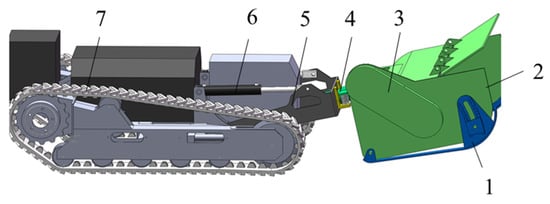
Figure 1.
The overall structure of the river dike mower: 1. Lawn protection boots; 2. Mowing device; 3. Hydraulic motor; 4. Profiling mechanism; 5. Header support; 6. Lifting hydraulic cylinder; 7. Crawler chassis.

Table 1.
Key structural parameters of river dike mowers.
2.2. Design of Key Components
2.2.1. Design of Lifting Mechanism
The lifting mechanism of the header incorporates three components: the base, the hydraulic cylinder, and the header support. The function of this mechanism lies in its ability to efficiently raise and lower the header. Notably, during the lifting and lowering process, the mower does not perform mowing operations. During mowing, the hydraulic cylinder incorporates a strategic amount of float, thus enabling longitudinal profiling and enhancing mowing precision. This structure is clearly depicted in Figure 2a.
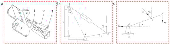
Figure 2.
Design of the header lifting mechanism: (a) Structure configuration of the header lifting mechanism: 1. Header support, 2. Lifting hydraulic cylinder, 3. Base; (b) Sketch map of the header lifting mechanism; (c) Force analysis diagram of the header support.
Let us consider the geometric relationships within this mechanism by assuming that the angle between the header support AC and the horizontal direction is a, and the angle between the hydraulic cylinder BC and the vertical direction is a2. Furthermore, when the piston rod of the hydraulic cylinder is fully retracted, the length of BC is LBC0. Additionally, let LBC0 be the length at which the piston rod starts to extend from the inner end of the hydraulic cylinder. Based on these geometric relationships, a comprehensive geometric model is constructed, as illustrated in Figure 2b.
In triangle ABC, there exists the following:
The following can be derived from Formula (2):
in the following formula: , .
LAB is the distance between the upper and lower articulation points on the support, LAC is the distance between the lower articulation point on the base and the articulation point on the header support, α2 is the angle between the line connecting the upper articulation point on the base as well as the lower articulation point on the hydraulic cylinder and the vertical direction, and f(x) is the function of the hydraulic cylinder’s extension displacement x.
The force situation of the header support in the vertical direction is elaborated in Figure 2c. The force and moment equilibrium equations of the header support are as follows:
In the formula, Fx is the horizontal force at the articulation point between the header support and the base, Fy is the vertical force at the articulation point, m is the mass of the header, Fe is the force exerted by the hydraulic cylinder, LAC is the distance between the articulation point of the header support and the base and the articulation point on the hydraulic cylinder, and LAD is the distance between the articulation point of the header support and the base and the connection point between the support and the header.
2.2.2. Design of Mowing Device
The Y-type swing blade stands out due to its diverse and notable characteristics, which includes its exceptional impact resistance, double-sided blade, wear resistance, formidable crushing ability, and uniform force distribution. This blade type has found widespread application in a range of mowers. Given its distinguished performance profile, the Y-type cutter, depicted in Figure 3a, has been selected as the primary blade for this study.
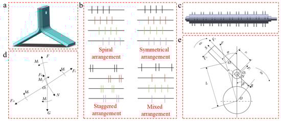
Figure 3.
Design of the mowing device: (a) Schematic diagram of cutter structure; (b) Arrangement of cutters; (c) Structure of the rollers; (d) Torque diagram of the cutter; (e) Force diagram of the cutter.
When configuring the blade arrangement on the roller, it is imperative to ensure that no cuts are missed during the mowing process and that there is no potential for blockages or interference among the blades. The typical blade arrangements include spiral, symmetrical, staggered, and symmetrical staggered configurations, as exemplified in Figure 3b. Among these four arrangements, the symmetrical layout offers uniformity in blade spacing, resulting in even stress distribution across the roller during rotation. Additionally, this arrangement simplifies the assembly process. Consequently, the roller of this mower has been designed with a symmetrical blade arrangement.
To determine the optimal number of cutters, it is of great significance to take careful consideration of the roller’s length and arrangement. An insufficient number of cutters can lead to missed cuts, compromising mowing efficiency. Conversely, an excess of blades can increase the torque and startup power of the roller, potentially resulting in blockages and entanglement issues. Hence, the number of cutters needs to be designed rationally []. Typically, the number of cutters is calculated using the following formula:
In the formula, n is the total number of cutters (piece), δ is the cutter density (piece/mm), straight blades are generally taken as 0.05 to 0.07 piece/mm, T-shaped blades are generally taken as 0.01 piece/mm, and LT is the distribution length of cutters on the roller, mm.
By substituting LT = 1400 mm into the equation, the number of cutters can be calculated as n = 36 pieces. The result is exhibited in Figure 3c.
The roller speed is a crucial parameter in the performance of the mower. Once the roller speed attains an optimal level, the cutters can execute an efficient cutting process []. Furthermore, the roller speed is intricately linked to the determination of the appropriate speed for the power mechanism, thereby emphasizing the necessity for a judicious choice of the roller speed []. Generally, the roller speed can be accurately determined through the application of Equation (5).
In the formula, va is the cutting speed of the blade (m/s), vm is the operating speed of the mower (m/s), and Rs is the rotational radius of the cutter root edge (m).
Research has embodied that to achieve effective cutting, the minimum linear velocity at the cutter root edge should not be less than 10 m/s, while the cutting speed of the cutter edge generally ranges from 20 to 50 m/s []. Take va = 25 m/s as an example. In this case, the forward speed of the mower is taken as vm = 0.8 m/s, and the rotational radius at the root is Rs = 120 mm. Substituting these values into Equation (5), we obtain n1 = 2054 r/min. Thus, the speed of the shaft is taken as 2100 r/min.
During the operational phrase, a force analysis of the cutter’s motion state has been conducted, as illustrated in Figure 3d,e. The forces acting on the cutter mainly consist of the gravitational force G of the cutter, the centripetal force S generated by the rotation of the cutter around the pin axis, the centripetal force F generated by the rotation of the cutter around the central axis, the normal pressure force N exerted on the connection point between the pin axis and the cutter, as well as the impact force Ft exerted by vegetation and soil on the front of the cutter during collision cutting and the frictional force Ff1 between vegetation and the cutter. The formulas for quantifying the impact force and frictional force, particularly when contaminants such as weeds and soil collide with and rub against the cutter, are as follows:
In the formula, M is the weight of impurities at the time of colliding (kg), Δv is the linear velocity difference at the time of colliding (m/s), t is the colliding time (s), and μ is the coefficient of friction between the cutter and the impurities.
At the rotational center point O1 of the cutter, the following exists:
The critical angle at which the cutter is relatively stationary to the center O1 of the pinhole is φ ≈ 1.4°. By substituting the various parameters of the cutter into Equation (8) we can accurately determine the precise pressure applied by the pin on the cutter, along with other pertinent values, at any specific moment in time.
2.2.3. Design of the Profiling Mechanism
The lateral profiling mechanism and its primary operational process are outlined in Figure 4a–c. When both ends of the header encounter minor bumps or pits in the terrain, the imbalance between the header and the ground surface triggers a rotational movement around the pivot axis. This rotational stability is maintained by a pair of springs, one in compression and the other in tension, jointly maintaining the overall equilibrium of the header. Specifically, if the left end of the header encounters a minor protrusion as the pivot axis rotates, the left spring assumes a tensile state, while the right spring compresses. Similarly, when the right end of the header encounters a bump or depression, the profiling mechanism responds with the corresponding lateral adjustment. This adaptive profiling is achieved through the concurrent stretching and compression of the springs at both ends, along with the rotational movement of the pivot axis, effectively delivering lateral profiling functionality at both extremities of the header.
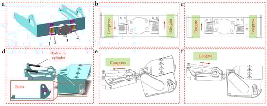
Figure 4.
Design of the profiling mechanism: (a) Schematic diagram of the transverse profiling mechanism: 1. Spring, 2. Upper guard plate, 3. Header connecting plate, 4. Lower support; (b,c) Operational status of the transverse profiling mechanism; (d) Schematic diagram of longitudinal profiling mechanism; (e,f) Operational status of the longitudinal profiling mechanism.
The longitudinal profiling mechanism and its primary operational process are visualized in Figure 4d–f. As the mower traverses terrain with significant elevation, the hydraulic cylinder initiates a retraction action. Conversely, when the mower encounters a deep depression in the soil, the hydraulic cylinder extends outward, thereby enabling profiling functionality in the longitudinal direction. This adaptive behavior ensures that the mower maintains optimal contact with the ground, regardless of the terrain’s irregularities.
2.2.4. Design of Hydraulic System
The design principle of hydraulic system for controlling the header lifting is illustrated in Figure 5. Initially, the electromagnetic valves 5 and 6 are set in their appropriate positions. As the header encounters a raised road surface, the hydraulic cylinder piston rod retracts. This retraction triggers a sequence of events: the oil flows through the appropriate side of electromagnetic valve 5, then passes through check valve 8, and ultimately returns to the oil tank through the hydraulic cylinder. Conversely, upon encountering a depressed road surface, the piston rod extends. At this point, oil pumped from the hydraulic cylinder passes through throttle valve 7, then flows through the right position of the electromagnetic valve 6, and finally returns to the oil tank. These two circuits are pivotal in achieving the longitudinal profiling functionality required for traversing embankment terrain. When it becomes necessary to lift the header, electromagnetic valve 5 is actuated to the left position. This allows the oil to flow from the hydraulic pump 2, through electromagnetic valve 5, then through check valve 8, and into the hydraulic cylinder. Once the oil passes through the cylinder, it returns to the oil tank. Conversely, for lowering the header, triggered by the activation of the stroke switch, electromagnetic valve 6 is shifted to its left position, facilitating their respective limit positions. This ensures that the lifting or lowering of the header is precisely controlled and halted at the desired heights.
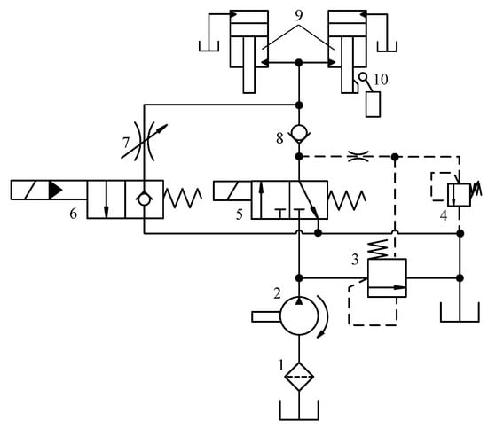
Figure 5.
Design of hydraulic system for header elevation control: 1. Oil filter; 2. Positive displacement hydraulic pump; 3. Differential pressure relief valve; 4. Safety valve; 5. Two-position three-way solenoid directional valve; 6. Two-position two-way solenoid directional valve; 7. Throttle valve; 8. Check valve; 9. Header lifting hydraulic cylinder; 10. Stroke switch.
The principal hydraulic components of the lawn mower comprise hydraulic motors dedicated to propulsion and cutter rotation, a hydraulic pump, cylinders, a reservoir, and valves, of which the meticulous calculation and selection of these components are paramount to ensure optimal performance [].
When it comes to hydraulic motors, the mower features both a traveling hydraulic motor and a blade rotation hydraulic motor. While the selection and calculation for the motor that rotates the cutter have already been addressed in a prior section, the focus now shifts to the selection and calculation of the propulsion hydraulic motor [,].
The torque required for the crawler drive is precisely known to be 1963.5 N·m, with a reduction ratio of 6 for the crawler section. As a result, the output torque of the hydraulic motor only needs to exceed Mk = 327.25 N·m to fulfill the power requirements. The displacement V of the traveling hydraulic motor can typically be determined using the following standard formula:
In the formula, p is the working pressure of the mower’s hydraulic system, and we assume it to be 20 MPa, and η is the volumetric efficiency of the high-speed hydraulic motor and we adopt a value of 0.9.
The maximum speed of the hydraulic motor is generally calculated by the following formula:
In the formula, vmax is the maximum speed of the mower, and we assume it to be 12 km/h, nmax is the rated maximum speed of the hydraulic motor (r/min), and rd is the selected drive radius of the crawler, and we set it to be 160 mm.
Put each value into the calculation to obtain V ≈ 120 mL/r, and nmax ≈ 200 r/min. Both the selected hydraulic motor displacements should meet 120 mL/r; and the maximum rated speed is 200 r/min. Based on various parameters of the mower’s movement, the hydraulic motor model BMR50 is selected as the traveling hydraulic motor.
Furthermore, other types of hydraulic components, including pumps, tanks, and valve components, are selected according to the required functionalities and parameters. This selection is made according to comprehensive operational analysis, considering both the practicality and cost-effectiveness of the various options. The detailed breakdown of the selection process for the various hydraulic components can be found in Table 2.
Table 2.
Main hydraulic components selection of mower.
2.3. Experiment Scheme
2.3.1. Simulation Experiment
As the lawn protection boot serves as the principal component responsible for transmitting forces between the header and the ground, this present study employs the software ANSYS2020 Workbench to perform a rigorous static analysis and optimization of the key structures of the boot. The mesh size is set to 2.437 mm. Furthermore, the material properties utilized in the study are outlined in Table 3.
Table 3.
Material property settings.
To access the dynamic behavior of the mower, which is the pivotal working unit, motion simulation analysis is conducted using the software ADAMS2020 []. Specifically, the roller shaft is configured with a rotational constraint, simulating a rotational speed of 2600 rpm, equivalent to the nominal operating speed of the mower. The simulation duration is set to 0.01 s, with a total of 5000 steps, ensuring a detailed and accurate representation of the mower’s operational dynamics.
2.3.2. Field Experiment
The experiment site is located on the river dike of the Yellow River, specifically in Mengjin County, Luoyang City, Henan Province, China, positioned at 34 degrees north latitude and 112 degrees east longitude. The experiment was performed beneath a clear sky. The river dike, an artificially constructed embankment, exhibits a slope ranging from 10 to 30 degrees and boasts a width of 3 to 5 m. The grass species within this locale are mainly composed of ryegrass, carpet grass, bermudagrass, and step grass, maintaining an average height of 23.2 cm and an average diameter of 40 mm.
- Test contents: The specific experiments include verifying the mower’s mowing speed [], validating mowing productivity [], testing the uniformity of mowing with and without profiling conditions, and analyzing the effect of the lawn protection boot at three different height adjustment positions during mowing.
- Test equipment: The key component is the prototype mower, other vital equipment includes a smartphone, a tape measure for accurate measurements (DELI with a range of 10 m and precision markings at the millimeter level), an angle gauge for assessing slopes (SOUTHERN JZC-B2 and measuring accuracy 1 Degree), a stopwatch for timing (CASIO HS-70W accurate to 1/100 s), and a marker bar for designation.
- Test methods: For the conduct of the experiment, a five-point sampling technique, also recognized as the diagonal method, is employed. This technique involves the selection of a uniformly spaced grassy area along the bank and the subsequent division of this area into five small rectangular sections arranged diagonally. The centers of four sample points are positioned equidistant from the center point on each diagonal. Each designated sample point encompasses an area of 0.25 square meters. The experiments are conducted on flat terrain and on slopes of 25 degrees, and the duration required for mowing each sample point is meticulously recorded [,]. The following is about validation test design:
- (1)
- The experimental design for the mowing speed and productivity:
Mowing speed and productivity are fundamental performance indicators of the mower during normal operational conditions. Only when these two parameters meet the design requirements can the mower be considered as compliant with the required performance criteria. Consequently, it is necessary to conduct experimental verification and analysis on both parameters.
- (2)
- The experimental design for a mowing height test in three gears of a lawn protection boots:
To ascertain the optimal mowing height for each gear, three distinct sections of embankment grassland are selected, ensuring similar terrain conditions and uniform grass height density across all test sites. The lawn protection boots are installed at gears one, two, and three, respectively, for mowing tests. After every two meters of mowing, the remaining stubble height is measured five times to ensure accurate data collection. The collected data are then organized into a comparative chart, allowing for a visual analysis of the remaining stubble heights across the three lawn protection boot positions.
- (3)
- The experimental design for comparing the uniformity of mowing with and without contour-following conditions on the header:
Two embankment grasslands, each 10 m in length and exhibiting slight unevenness, are selected as test sites. Both grasslands possess identical grass density, height, and other relevant parameters, facilitating a fair comparison between the two conditions. Initially, the mower without the profiling mechanism is tested on Grassland One. Following the mowing process, the stubble height is measured at 2-m intervals, totaling 5 sampling points. The same procedure is repeated with a mower equipped with the profiling mechanism on Grassland Two, with the stubble height at 2-m intervals to obtain another set of data.
3. Results and Discussion
3.1. Analysis of Simulation Results
The header exhibits a gravity load of 160 kg, bearing a lawn protection boot force of 1600 N. Given the structural characteristics of the lawn protection boots, one end has borne 1000 N while the other has borne 600 N, as manifest in Figure 6a. As illustrated in Figure 6b,c, the maximum stress on the sliding boots has reached 137.57 MPa, accompanied by a maximum deformation of 0.35 mm, indicating notable regions of stress concentration. To alleviate stress concentration and streamline the design, a thorough optimization of the lawn protection boot’s structure is required. A range of optimization methods, including shape optimization, structural topology optimization, and dimension optimization, are available. For this specific optimization, dimension optimization and shape optimization are chosen. The optimization process involves making strategic modifications to the design. Small blocks are excised from the locking points of the lawn protection boots and replaced with three pairs of locking holes. This approach reduces the weight and overall dimensions of the lawn protection boots, thereby simplifying the installation process. The simulation analysis of the optimized lawn protection boot structure reveals intriguing results. As presented in Figure 6d–i, the highest stress points consistently occur at the juncture between the bottom support plate and the base plate of the boots across gears one, two, and three. In gears one and two, the maximum deformation occurs at the apex of the upper support plate, while in gear three, the point of maximum deformation shifts to the highest point of the boot base. As the gear levels progress, both the maximum stress and total deformation exhibit a decreasing trend. Across all three gear levels, the peak stress recorded is 44.52 MPa. This value falls well within the yield strength of the material Q235 used for the lawn protection boots, which is rated at 235 MPa. Thus, the optimized design meets the required standards, ensuring durability and reliability in agricultural applications.
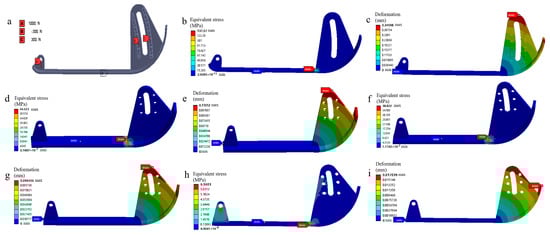
Figure 6.
Static analysis of the lawn protection boots: (a) Load and constraint settings of the lawn protection boot; (b,c) Equivalent stress and deformation contour plots of the lawn protection boot; (d–i) Equivalent stress and deformation contour plots of the optimized lawn protection boot in gears one through three.
After enhancing the design of the lawn protection boots, a substantial reduction in stress and deformation is observed. According to the comparison of stress and deformation cloud maps before and after the improvements [], the maximum stress exerted on the boots decreases significantly, from 135.57 MPa to 44.52 MPa, representing a notable drop of 91.05 MPa. Similarly, the maximum deformation also decreases markedly, dropping from 0.35 mm to 0.11 mm, a momentous reduction of 0.24 mm. These findings clearly indicate that the stress concentration within the lawn protection boots has been significantly mitigated, highlighting the effectiveness of the enhancements made.
The kinematic simulation model of the mower device is depicted in Figure 7a. As evident in Figure 7b–d, the mower undergoes a start-up phase ranging from 0 to 0.005 s, during which there are significant fluctuations in the blade speed. Subsequently, the blade speed gradually stabilizes and eventually converges to approximately 2600 rpm, closely matching the roller speed. Similarly, the highest and lowest points of the blade exhibit comparable fluctuations. Although the trajectory of the blade tip initially appears irregular, it ultimately stabilizes into a circular motion centered around the roll axis. This observation suggests that the cutters on the roller are arranged and distributed in a uniform and reasonable manner, fulfilling the requirements for high-speed mower operation.
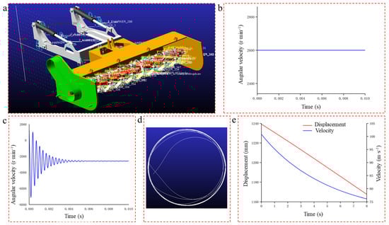
Figure 7.
Kinematic simulation analysis of the header: (a) Results of simulation model construction; (b) Variation of roller shaft angular velocity; (c) Variation of the cutter center angular velocity; (d) Motion trajectory curve of blade tip; (e) Velocity and displacement curves at the centroid of the header.
To further validate the rationality of the mower lifting mechanism design, a simulation analysis of the mower lifting mechanism can be conducted []. This simulation thoroughly examines the motion characteristics of the header during the lifting process, thereby verifying the functionality of the lifting mechanism. The simulation modeling process involves importing the model by adding constraints, kinematic subs, and drivers. Drawing upon the findings of previous conclusion, which indicate that the hydraulic cylinder stroke is 160 mm, and the lifting time should not exceed 10 s, we assume a lifting speed of 20 mm/s for the hydraulic cylinder every 20 mm of upward movement. Consequently, the simulation is executed for a duration of 8 s, divided into 200 discrete steps. By observing the lifting situation of the header, as presented in Figure 7e, we can deduce that during the lifting process, the maximum speed reached is 100.8 mm/s, while the minimum speed is 76.1 mm/s. This comprehensive simulation analysis confirms that the design and parameter selection of the header lifting mechanism align with the intended working conditions and satisfy the designated design requirements.
3.2. Analysis of Field Experiment Results
3.2.1. Mower Mowing Speed and Productivity Experiment Verification
Experimental principle: The operational speed of the mower is calculated according to the following formula, and the average of five measurements is taken at the end:
In the formula, v is the machine working speed (m/s), ∑L is the total length of the area, which is determined by the experiment (m), and ∑t is time spent (s).
Specific steps: Five 10-m sites are selected on flat ground with a 25° slope. Under normal mower operating conditions, the time taken for mowing is recorded at each sample point. Finally, the speed values of the five sample points on flat ground and the 25° slope are calculated using Formula (11), as presented in Table 4.
Table 4.
Mower mowing speed on flat ground and a 25° slope.
The mowing productivity of a mower serves as a key parameter for assessing the effectiveness of its header design, which in turn serves as an indirect indicator of the success of the mower’s profiling. The following outlines the methodology for verifying the mowing productivity of a mower:
Experimental principle of mowing productivity of mower:
In the formula, p is mowing productivity (m2/s), A is Area of mowing (m2), and t is mowing time (s).
Specific steps: Five plots of land are selected, including flat ground and featuring a 25° slope, as depicted in Figure 8d. Each plot measures 10 m in length and width, facilitating the conduct of precise mowing experiments. During these experiments, the width of the mower’s cutting swath is measured, and the time taken for each mowing session is recorded. These data are then utilized to compute the mowing productivity by using the Formula (12).
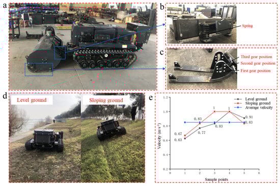
Figure 8.
Machine prototype and field experiment: (a) Overall machine structural configuration; (b) Lateral profiling mechanism; (c) Lawn protection boot; (d) Flat and sloping ground tests; (e) Mowing speed analysis.
The measured width of the mower’s cutting swath is determined to be 1.3 m. By substituting these values into Formula (12), the mowing productivity on flat ground and the 25° slope is calculated, respectively, as presented in Table 5.
Table 5.
Mowing productivity of the mower on flat ground and a 25° slope.
The results of the processed prototype mower are presented in Figure 8a–c. Its operating efficiency is evaluated on both flat ground and a 25° slope. The experiment area and the corresponding results are depicted in Figure 8d,e. Notably, the average working speed of the mower on both flat ground and slopes is recorded as 0.85 m/s. This speed falls squarely within the designed mowing speed range of 0.27 m/s to 2.7 m/s, thus fulfilling the designated requirements.
A comparative graph of mowing speeds derives from speed curve graphs plotted for mowing on flat ground with a 25° slope. This is clearly manifested in Figure 8e. From the graph, it can be observed that under normal operating conditions, the mower exhibits nearly identical mowing speed on both flat and sloped terrain. Notably, the speed stabilizes at 0.85 m/s. This speed falls within the predefined mowing speed range of 1 km/h to 10 km/h, thus fulfilling the established design criteria.
The values presented in Table 5 reveal an average mowing productivity of 3872 m2/h on flat ground and an even higher rate of 4212 m2/h on a 25° slope. Notably, both of these averages exceed the minimum stipulated requirement of 3000 m2/h for the mower’s designated mowing productivity. Therefore, it can be confidently concluded that the header effectively meets the established design requirements for mowing operations.
The mower’s productivity when mowing on a 25° slope is higher compared to flat ground. This is primarily because of its ability to adjust to changes in the terrain’s elevation, allowing it to maintain a consistent cutting effect. Additionally, the force of gravity on the slope provides the mower with extra power, resulting in more efficient mowing on sloped surfaces.
3.2.2. Experiment Verification of a Mowing Height Test in Three Gears of Lawn Protection Boots
To assess the functional efficiency of the lawn protection boots, extensive tests have been conducted at three different gear positions, each tailored to varying cutter heights relative to the ground: gear position 1 set at a cutter height of 6 cm, gear position 2 at 8 cm, and gear position 3 at 10 cm.
The results of these tests are depicted in Figure 9a,b. It is observed that the differences in mowing height among the three gears increase at almost the same rate. Specifically, the average stubble height for Gear 1 is recorded as 10.4 cm, Gear 2 exhibited 12 cm, and Gear 3 yielded 14 cm. Notably, the height disparities among the three gears are approximately 2 cm, and the total time required for gear adjustments does not exceed 5 min, thus meeting the design requirement for gear modulation in the boots.
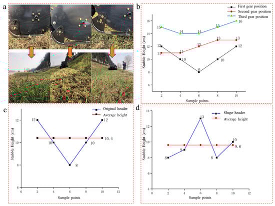
Figure 9.
Comprehensive performance experiment of header: (a) Effect of three-speed change experiment of lawn protection boot; (b) Stubble height after three-speed change of lawn protection boot; (c) Stubble height of conventional header operation; (d) Stubble height for profiling header operation.
3.2.3. Comparison Experiment of Mowing Uniformity with and without Profiling of the Header
Furthermore, to evaluate the operational effectiveness of the profiling header, a comparative analysis is conducted between a traditional header and the profiling header, as manifested in Figure 9c,d. The stubble heights for platforms devoid of profiling and those equipped with profiling are calculated using Equation (13), yielding values of μN = 10.4 cm and μY = 9.6 cm, respectively. In this case, ‘N’ and ‘Y’ serve as abbreviations, representing platforms without a profiling header and with a profiling header, respectively.
In the formula, μ is the mean stubble height; xi is the sum of stubble height; and n is the number of sampled data points.
Then, utilizing the variance calculation Formula (14), we can compute the variance to obtain a value of = 2.24, and = 3.34.
Here, σ2 is the variance; (xi − μ)2 is the sum of squares of the differences between each data point and the mean value; and n is the number of sampled data points. Then, using Formula (15), we can obtain the standard deviation of σN = 1.497 and σY = 1.828. Finally, we employ the coefficient of variation using Formula (16), and then acquire CVN = 14.39% and CVY = 19.04%. Here, σ is standard deviation; and CV is coefficient of variation.
After the comparison between the performance data of the profiling headers and non-profiling (traditional) headers, it is evident that the profiling header exhibits a slightly higher standard deviation of 1.828 compared to 1.497 for the non-profiling header. In addition, the coefficient of variation of the profiling header, standing at 19.04%, is also slightly higher than that of the 14.39% of the non-profiling header. These findings indicate that during the mowing process, the performance of the profiling header exhibits relatively greater fluctuations and variability.
A higher standard deviation signifies that the profiling header demonstrates greater variance in the measured data. This may reflect pronounced differences in its performance across diverse conditions or at various times. Moreover, the elevated coefficient of variation further corroborates the relatively unstable performance of the profiling header, which can be attributed to a range of factors, including variations in terrain, crop type, or operating parameters.
The performance data of the profiling header exhibits certain fluctuations; however, it remains within the design specifications for crucial indicators such as mowing height. The fact that the deviation amount remained within the permissible range underscores the overall reliability and practicality of the system.
4. Conclusions
- (1)
- This simulation verifies the functionality of the lifting mechanism by closely analyzing the motion characteristics of the header during the lifting process. Based on this information, we can deduce that the lifting process achieved a peak velocity of 100.8 mm/s and a minimum velocity of 76.1 mm/s. This comprehensive simulation analysis confirms that the design and parameter selections of the header lifting mechanism satisfy the specified design requirements and align with the intended working conditions.
- (2)
- Significantly, the mower maintains a consistent operating speed of 0.85 m/s on both flat and sloping terrain. This velocity falls precisely within the designated range of 0.27 m/s to 2.7 m/s, which is the intended speed for mowing. The findings indicated a significantly greater rate of 4212 m2/h on a 25° incline, while the average mowing efficiency on flat terrain was 3872 m2/h. Notably, both of these averages exceed the minimum stipulated requirement of 3000 m2/h for the mower’s designated mowing productivity, thus fulfilling the designated requirements.
- (3)
- An experiment was conducted to determine the maximum level of gear adjustment for the lawn protection boots. Notably, the height differences between the three gears are only about 2 cm, which meets the design requirement for gear modulation in the boots. When assessing the uniformity of mowing with and without a profiling header, the validation indicates that the former exhibits a slightly greater standard deviation (1.828) compared to the latter (1.497). Essentially, the profiling header adapts to the transformation of river dikes within an acceptable range of variation and meets the design criteria for important factors such as the evenness of mowing.
Author Contributions
Conceptualization, M.L.; methodology, M.L.; software, M.L. and Y.Y.; validation, M.L. and Y.Y.; formal analysis, M.L. and Y.Y.; investigation, M.L., Y.Y. and L.T.; resources, M.L. and L.T.; data curation, M.L.; writing—original draft preparation, M.L., Y.Y. and L.T.; writing—review and editing, X.C. and F.L.; visualization, M.L. and L.T.; supervision, X.C., F.L. and M.L.; project administration, M.L. All authors have read and agreed to the published version of the manuscript.
Funding
This research has been funded by the Chongqing Special Key Project for Technological Innovation and Application Development, under the grant number cstc2021jscx-gksb0003.
Institutional Review Board Statement
Not applicable.
Data Availability Statement
The datasets used and/or analyzed during the current study are available from the corresponding author upon reasonable request.
Conflicts of Interest
The authors declare that they have no conflicts of interest pertaining to the content, execution, or publication of this research.
References
- GB 50286-2013; Code for Design of Embankment Slope Engineering. Ministry of Water Resources of the People’s Republic of China: Beijing, China, 2013.
- 2019 National Water Conservancy Development Statistics Bulletin; Ministry of Water Resources of the People’s Republic of China: Beijing, China, 2019.
- Bátori, Z.; Kiss, P.J.; Tölgyesi, C.; Deák, B.; Valkó, O.; Török, P.; Erdős, L.; Tóthmérész, B.; Kelemen, A. River embankments mitigate the loss of grassland biodiversity in agricultural landscapes. River Res. Appl. 2020, 36, 1160–1170. [Google Scholar] [CrossRef]
- Löbmann, M.T.; Geitner, C.; Wellstein, C.; Zerbe, S. The influence of herbaceous vegetation on slope stability—A review. Earth-Sci. Rev. 2020, 209, 103328. [Google Scholar] [CrossRef]
- Cole, L.J.; Stockan, J.; Helliwell, R. Managing riparian buffer strips to optimise ecosystem services: A review. Agric. Ecosyst. Environ. 2020, 296, 106891. [Google Scholar] [CrossRef]
- Vannoppen, W.; Poesen, J.; Peeters, P.; De Baets, S.; Vandevoorde, B. Root properties of vegetation communities and their impact on the erosion resistance of river dikes. Earth Surf. Process. Landf. 2016, 41, 2038–2046. [Google Scholar] [CrossRef]
- Scheres, B.; Schüttrumpf, H. Investigating the erosion resistance of different vegetated surfaces for ecological enhancement of sea dikes. J. Mar. Sci. Eng. 2020, 8, 519. [Google Scholar] [CrossRef]
- van den Hoven, K.; Grashof-Bokdam, C.J.; Slim, P.A.; Wentholt, L.; Peeters, P.; Depreiter, D.; Koelewijn, A.R.; Stoorvogel, M.M.; van den Berg, M.; Kroeze, C.; et al. Greening the dike revetment with historic sod transplantation technique in a living lab. J. Flood Risk Manag. 2024, 17, e12968. [Google Scholar] [CrossRef]
- Zanetti, C.; Macia, J.; Liency, N.; Vennetier, M.; Mériaux, P.; Provensal, M. Roles of the riparian vegetation: The antagonism between flooding risk and the protection of environments. In Proceedings of the 3rd European Conference on Flood Risk Management FLOODrisk, Lyon, France, 17–21 October 2016; Volume 7, p. 13015. [Google Scholar]
- van der Meer, J.; Steendam, G.J.; Mosca, C.A.; Guzzo, L.B.; Takata, K.; Cheong, N.S.; Eng, C.K.; Lj, L.A.; Ling, G.P.; Siang, C.W.; et al. Wave overtopping tests to determine tropical grass species and topsoils for polder dikes in a tropical country. Coast. Eng. Proc. 2020, 36, 31. [Google Scholar] [CrossRef]
- Orlyanskaya, I.A.; Jhalnin, E.V.; Orlyansky, A.V.; Petenev, A.N.; Kulaev, E.V. Comparative efficiency of segment-finger and rotary mowers for grass cutting. In Proceedings of the AIP Conference Proceedings, Stavropol, Russia, 27–30 September 2021; Volume 2661, p. 070002. [Google Scholar]
- Nishimura, Y.; Yamaguchi, T. Grass Cutting Robot for Inclined Surfaces in Hilly and Mountainous Areas. Sensors 2023, 23, 528. [Google Scholar] [CrossRef] [PubMed]
- Liao, J.C.; Chen, S.H.; Zhuang, Z.Y.; Wu, B.W.; Chen, Y.J. Designing and Manufacturing of Automatic Robotic Lawn Mower. Processes 2021, 9, 358. [Google Scholar] [CrossRef]
- Xiao, M.H.; Zhao, Y.; Wang, H.; Xu, X.; Bartos, P.; Zhu, Y. Design and Test of Hydraulic Driving System for Undercarriage of Paddy Field Weeder. Agriculture 2024, 14, 595. [Google Scholar] [CrossRef]
- Kang, C.Q.; Ng, P.K.; Liew, K.W. The Conceptual Synthesis and Development of a Multifunctional Lawnmower. Inventions 2021, 6, 38. [Google Scholar] [CrossRef]
- Khodke, K.R.; Kukreja, H.; Kotekar, S. Literature Review of Grass Cutter Machine. Int. J. Emerg. Technol. Eng. Res. 2018, 6, 97–101. [Google Scholar]
- Diwakaran, S.; Kumar, M.D.V.; Mohanreddy, P.S.; Rishika, C.; Sreenivasulu, P.; Sivasubramanian, M. Design of an Autonomous Mower with Height Adjustable Cutting Motor. In Proceedings of the 2023 4th International Conference on Signal Processing and Communication (ICSPC), Coimbatore, India, 23–24 March 2023; pp. 348–352. [Google Scholar]
- Kang, C.Q.; Ng, P.K.; Liew, K.W. A TRIZ-Integrated Conceptual Design Process of a Smart Lawnmower for Uneven Grassland. Agronomy 2022, 12, 2728. [Google Scholar] [CrossRef]
- Lei, X.H.; Qi, Y.N.; Zeng, J.; Yuan, Q.C.; Chang, Y.H.; Lyu, X. Development of unilateral obstacle-avoiding mower for Y-trellis pear orchard. Int. J. Agric. Biol. Eng. 2022, 15, 71–78. [Google Scholar] [CrossRef]
- Wu, B.; Wang, D.; Wang, G.; Fu, Z.; Guo, Z.; Gong, Z.; Li, T. Design and Simulation of the Copying Spring of Selfpropelled Mowers. In Proceedings of the 2015 ASABE Annual International Meeting, New Orleans, LA, USA, 26–29 July 2015; p. 152188918. [Google Scholar]
- Zhang, Y.; Tian, L.; Cao, C.; Zhu, C.; Qin, K.; Ge, J. Optimization and validation of blade parameters for inter-row weeding wheel in paddy fields. Front. Plant Sci. 2022, 13, 1003471. [Google Scholar] [CrossRef] [PubMed]
- Sheng, Y.Y.; Tian, C.Y.; Xiao, M.H.; Yao, W.Q.; Wang, Q.Q.; Shi, X.Y. Design and Analysis of a Portable Greenhouse Weeding Machine. J. Comput. Methods Sci. Eng. 2019, 19, 229–241. [Google Scholar] [CrossRef]
- Tian, F.; Xia, K.; Wang, J.; Song, Z.; Yan, Y.; Li, F.; Wang, F. Design and experiment of self-propelled straw forage crop harvester. Adv. Mech. Eng. 2021, 13, 16878140211024455. [Google Scholar] [CrossRef]
- Nkakini, S.; Branly, Y. Design, Fabrication and Evaluation of a Spiral Blade lawn mower. Eur. Int. J. Sci. Technol. 2014, 3, 165–172. [Google Scholar]
- Zhao, L.; Wang, J.; Zhang, Z.W. Research on Parameter Design of Multi-axis Hydrostatic Transmission Vehicle. MATEC Web Conf. 2017, 139, 00215. [Google Scholar] [CrossRef][Green Version]
- Cao, L.; Miao, S. Design of Chinese Cabbage Harvester. In Proceedings of the 2020 IEEE International Conference on Mechatronics and Automation (ICMA), Beijing, China, 13–16 October 2020; pp. 243–248. [Google Scholar]
- Guan, P.; Yang, J. Design and test of a new type of coupling weeder. Int. J. Mech. 2023, 17, 16–24. [Google Scholar] [CrossRef]
- Zhang, L.; Yao, C.; Ying, W.; Luo, S.; Ying, F. Theoretical analysis and design of roller mower straight blade. J. Mech. Sci. Technol. 2024, 38, 3597–3606. [Google Scholar] [CrossRef]
- Pirchio, M.; Fontanelli, M.; Frasconi, C.; Martelloni, L.; Raffaelli, M.; Peruzzi, A.; Gaetani, M.; Magni, S.; Caturegli, L.; Volterrani, M.; et al. Autonomous Mower vs. Rotary Mower: Effects on Turf Quality and Weed Control in Tall Fescue Lawn. Agronomy 2018, 8, 15. [Google Scholar] [CrossRef]
- Iwano, Y.; Hasegawa, T.; Tanaka, A.; Iizuka, K. Development of the trimmer-type mowing system against a slope. In Proceedings of the 2016 International Conference on Advanced Mechatronic Systems (ICAMechS), Melbourne, VIC, Australia, 16 January 2017; pp. 23–28. [Google Scholar]
- Fontanelli, M.; Chiaro, N.D.; Gagliardi, L.; Frasconi, C.; Raffaelli, M.; Peruzzi, A.; Luglio, S.M. Measuring the operative performance of autonomous mowers on slopes. In Proceedings of the 2023 IEEE International Workshop on Metrology for Agriculture and Forestry (MetroAgriFor), Pisa, Italy, 6–8 November 2023; pp. 404–408. [Google Scholar]
- Yan, J.; Gao, L.; Wang, L.; Gong, X. Design, finite element analysis and utility of automatic weeder for port. Coast. Res. 2019, 93, 901–904. [Google Scholar] [CrossRef]
- Peigang, J.; Yinnan, L.; Yang, L. Design and Simulation Analysis of Weeding Machine Chassis Based on CATIA and ADAMS. In Proceedings of the 2023 International Conference on Electronics and Devices, Computational Science (ICEDCS), Marseille, France, 22–24 September 2023; pp. 158–162. [Google Scholar]
Disclaimer/Publisher’s Note: The statements, opinions and data contained in all publications are solely those of the individual author(s) and contributor(s) and not of MDPI and/or the editor(s). MDPI and/or the editor(s) disclaim responsibility for any injury to people or property resulting from any ideas, methods, instructions or products referred to in the content. |
© 2024 by the authors. Licensee MDPI, Basel, Switzerland. This article is an open access article distributed under the terms and conditions of the Creative Commons Attribution (CC BY) license (https://creativecommons.org/licenses/by/4.0/).