Article

Design and Preliminary Experiment of Track Width Adjustment System for Sprayer Based on Integral Separated Fuzzy Proportional Integral Derivative Control Strategy

1
College of Engineering, China Agricultural University, Beijing 100083, China
2
Key Laboratory of Agricultural Equipment for Conservation Tillage, Ministry of Agricultural and Rural Affairs, Beijing 100083, China
*
Author to whom correspondence should be addressed.
Agriculture 2024, 14(8), 1247; https://doi.org/10.3390/agriculture14081247 (registering DOI)
Submission received: 22 June 2024 / Revised: 24 July 2024 / Accepted: 26 July 2024 / Published: 28 July 2024

Abstract

:
Different agronomic requirements, production conditions, and crop species result in varying row spacings. To address the issue of seedling damage caused by pressure when a fixed track width sprayer operates in different row spacings and enhance the accuracy of track width adjustment, this study designed a track width adjustment system for a sprayer based on the agronomic requirements for field management during the early and mid-stages of corn growth and the entire growth period of wheat in Henan Province, China. The designed track width adjustment system for the sprayer comprised transmission mechanisms, telescopic track width adjustment mechanisms, and an electro-hydraulic control system. The control system achieved a precise track width adjustment by controlling the movement of the hydraulic cylinders through electrical signals, forming a closed-loop adjustment system with the aid of sensors. Four control schemes are proposed: classical PID, integral separated PID, fuzzy adaptive PID, and integral separated fuzzy PID. Simulation experiments were conducted using MATLAB to compare these schemes. The results indicated that the integral separated fuzzy PID exhibited the fastest response and highest steady-state accuracy. The performance of the track width adjustment system was validated through field experiments. The results demonstrate that the stability coefficient of variation for the track width adjustment was 3.04%, which is below the 10% threshold required by agricultural machinery standards. Additionally, the average error of the track width adjustment was 13.42 mm, indicating high precision and effectively reducing seedling compression damage during plant protection operations.

1. Introduction

As China’s major grain crops, the national total production of wheat and corn in 2023 reached 136.59 million tons and 288.84 million tons, respectively, accounting for 61.18% of the country’s total grain production. Consequently, enhancing the production capacity of wheat and corn is crucial for ensuring China’s food security [1,2]. Plant protection technology, which mitigates the threats posed by diseases, pests, and weeds to crops, creates favorable growing and developing conditions for crops, thus helping to ensure crop quality and increase yields [3]. Therefore, the adoption of efficient and comprehensive plant protection technologies during the growth of wheat and corn is an inevitable choice for modern agricultural production.
Boom sprayers are widely used in field plant protection operations with their advantages of high spraying quality and operational efficiency. In recent years, China has placed increasing emphasis on the research and promotion of plant protection machinery, conducting extensive studies on boom sprayers. By incorporating electronic control technology and hydraulic technology and equipping them with GPS or Beidou Navigation Satellite Systems, these sprayers are continually evolving toward being more intelligent, efficient, and environmentally friendly [4,5,6].
China’s diverse ecological environment and complex terrain result in varying agronomic requirements and field operation needs for crop planting methods across different regions [7]. This diversity leads to fixed track width sprayers crushing crops during operations in fields with different row spacings, causing crop damage and reducing yields. Therefore, designing an intelligent track width adjustment system for the chassis of the sprayer, which accommodates various planting row spacings, is of great significance for enhancing the sprayer’s adaptability to different environments, promoting increased crop yields, and reducing production costs.
Track width adjustment devices are widely used in agricultural machinery such as agricultural chassis, rear wheels of wheeled tractors, and high-clearance vehicles with four-wheel diamond arrangements. They can be categorized into stepwise adjustment and stepless adjustment, depending on whether the track width can be adjusted to any position within the adjustable range [8]. Currently, the stepwise adjustment method for track width mainly relies on manual adjustments, typically implemented through mechanisms such as wheel hub cap clamping, rim flipping, and hub spacers. For instance, the Dongfanghong LX750H, manufactured by China YTO Group Corporation in Luoyang, China, achieves track width adjustment by replacing the front and rear axles. The Case New Holland (China) Management Co., Ltd. located in Shanghai produces the TS6.120 high-clearance tractor, which adjusts its track width by flipping the tires. The Case IH PatriotTM 3230 sprayer, also manufactured by the company, adapts to different row spacings through optional configurations, with an adjustment range of 3050 to 3990 mm and an adjustment increment of 25 mm. Its track width position stop must be manually determined, and the sliding bar is marked with raised text indicating the track width [9]. While stepwise adjustment is reliable and widely used, it is time-consuming and labor-intensive. At the same time, it increases the cost of some sprayers and lacks precision.
Currently, both domestically and internationally, electro-hydraulic control technology or fully electronic control methods are predominantly used for stepless adjustment of the track width in agricultural machinery. This is achieved by driving the corresponding mechanical structures through hydraulic cylinders or electric actuators to implement track width adjustment functions. The primary mechanical structures used include linkage mechanisms, telescopic adjustment sleeves, sliding bearings, and gear racks. Among these, linkage mechanisms and telescopic adjustment sliding sleeve mechanisms are widely used. Zhang, Q. [10] employed a hydraulic mechanism to drive a parallel four-bar linkage, thereby adjusting the track width and ground clearance. This design ensures high stability for the sprayer under hilly and mountainous working conditions. Liu et al. [11] designed a self-propelled adjustable sprayer that uses eight connecting rods to hinge the walking main beam and the frame together, with each hydraulic cylinder independently controlling a single walking main beam, allowing for single-side track width adjustments. Although linkage adjustment of the track width is compact and enables stepless adjustment, it is structurally complex and difficult to manufacture.
Compared to linkage mechanisms, a telescopic adjustment sliding sleeve structure is simpler and it is easier to achieve any desired track width adjustment [12]. Li, J. [13] utilized the telescopic motion of hydraulic cylinders to directly drive a sprayer wheel with leg mounting brackets to move laterally along guide rails. A Watt balance linkage ensures that the movement distance of the left and right wheel leg mounting brackets remains equal. The structure is compact, but it lacks a design for the software control component. Xia et al. [14] designed a track width adjustment device for the rear wheels of wheeled tractors, which connects the rim and hydraulic adjustment system through the inner and outer rings of a sliding bearing. The hydraulic cylinder piston is moved by a directional valve, and the sliding bearing drives the rim to move left and right. Chipriana et al. [15] designed and implemented a high-clearance sprayer where the movable support wheel frames on both sides are mounted on the framework through U-shaped arms, and the track width is adjusted by moving the two support wheel frames along sliding rails with hydraulic cylinders. The high-clearance sprayer designed by Italy’s SPAPPERI for tobacco is equipped with real-time monitoring technology, allowing for real-time track width adjustments from the cab [16]. Zhang et al. [17] studied a hydraulically adjustable chassis with machine vision, where a microcontroller plans the optimal driving route based on images of the drive wheel’s front view captured by a camera. It then controls digital hydraulic cylinders to move the fixed frame along guide rods, with the drive wheel and motor moving along with the fixed frame. This chassis enables independent left and right track width adjustments and real-time automatic track width adjustments based on ground conditions.
In the aforementioned study, although the use of a fully electronic control for track width adjustment offers higher precision and eliminates hydraulic impact, its load-bearing capacity is relatively small, making it unsuitable for large agricultural machinery. Therefore, the current practical application of stepless track width adjustment mainly relies on electro-hydraulic control technology. The electro-hydraulic control technology for track width adjustment in sprayers typically uses open-loop control, which has the issue of excessive hydraulic cylinder impact, leading to significant wear on tires, frames, and guide rails, and also lacks precision. Adding sensors to the electro-hydraulic control technology for closed-loop adjustment can improve the accuracy of track width adjustment.
Therefore, to avoid seedling damage caused by fixed track width sprayers when operating between different row spacings, and to improve the stability and precision of the sprayer’s track width adjustment, this paper designed a track width adjustment system for the sprayer based on electro-hydraulic control and an integral separated fuzzy PID control strategy. The performance of the system was validated through field experiments.

2. Materials and Methods

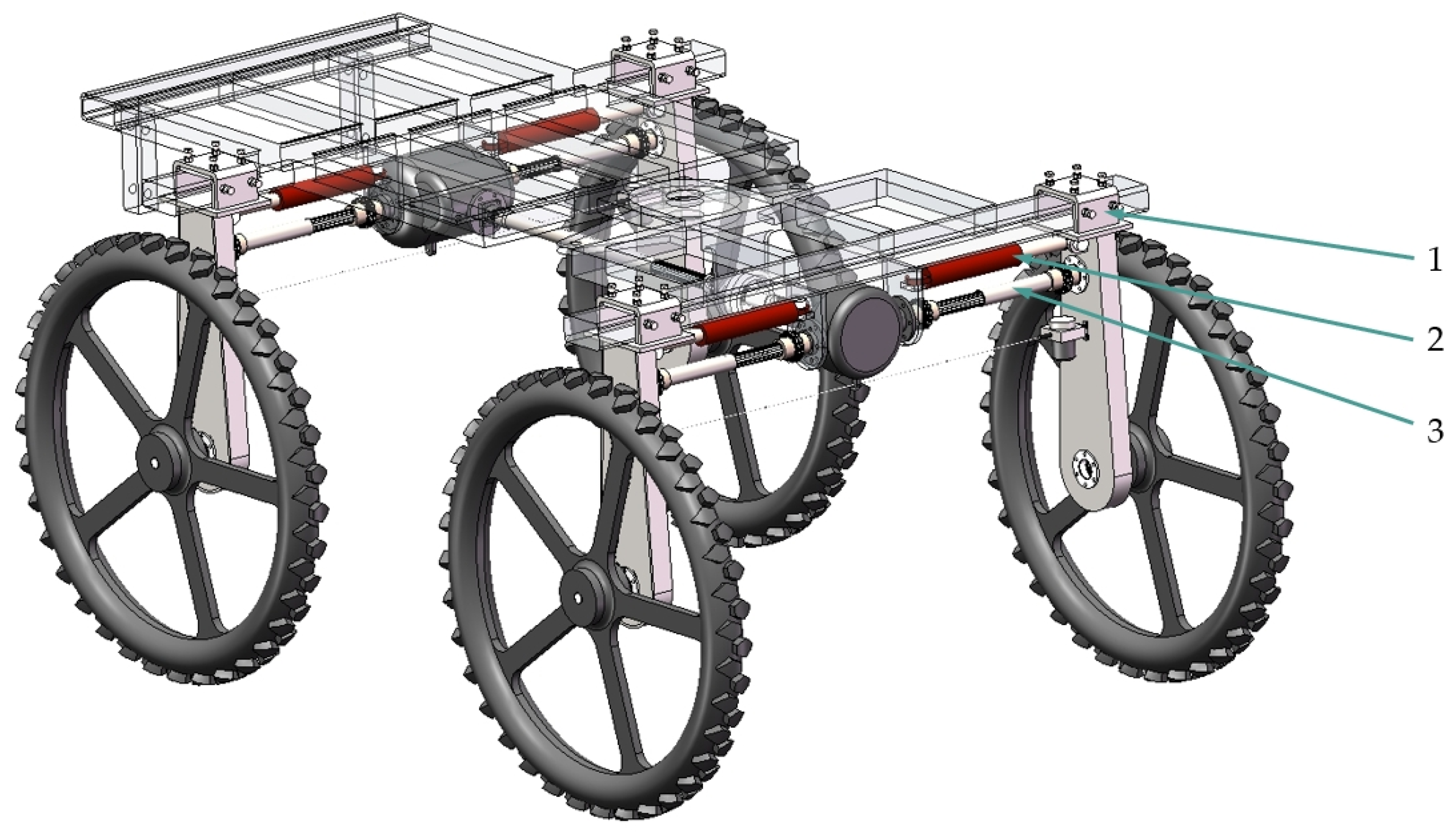
2.1. Overall Structure of the Track Width Adjustment System

The 3WP-280 self-propelled boom sprayer is utilized as the platform for the track width adjustment system. As illustrated in Figure 1, the track width adjustment system is primarily comprised of a transmission mechanism, telescopic track width adjustment mechanism, and electro-hydraulic control system.
The transmission mechanism transfers the engine’s power to the gearbox, generator, and hydraulic pump, thereby providing a power source for the electro-hydraulic control system and the wheels. The telescopic track width adjustment mechanism connects the left and right support wheel frames to the central body chassis. Under the driving force of the hydraulic cylinder, the support wheel frames can slide along the sprayer’s crossbeam. The electro-hydraulic control system detects the real-time adjustment distance of the track width and adjusts the lateral movement speed and distance of the movable tire support bracket on both sides in real-time based on the detected track width values.

2.2. Design of Key Components of the Track Width Adjustment System

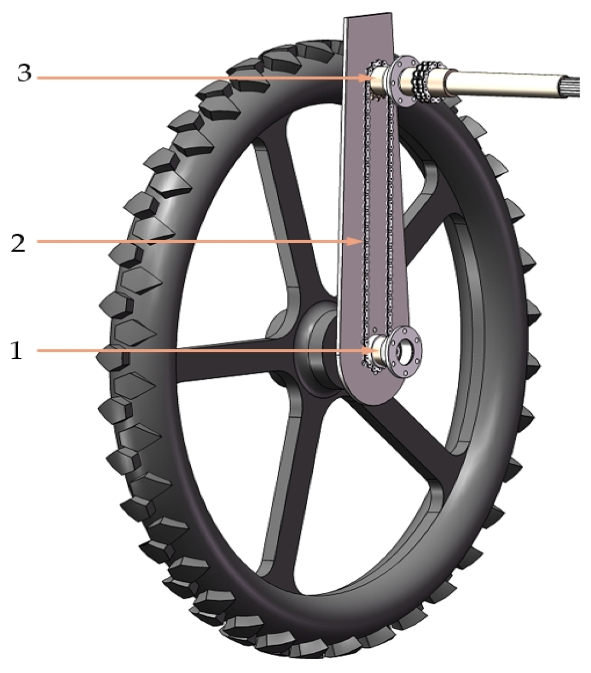
2.2.1. Transmission Mechanism

The transmission mechanism includes the drive shaft assembly and the wheel-side drive components. As shown in Figure 2, in the drive shaft assembly, two double-row chain couplings sequentially connect the differential half-shaft to the splined driving shaft and the splined driven shaft sleeve to the sprocket box input shaft. The splined driven shaft sleeve rotates with the splined driving shaft while being able to slide left and right along the driving shaft, facilitating track width adjustment during the sprayer’s operation. The power transmission path is sequentially as follows: differential left and right half-shafts, double-row chain coupling, splined driving shaft, splined driven shaft sleeve, double-row chain coupling, and sprocket box input shaft.
As shown in Figure 3, the wheel side drive component mainly consists of a sprocket box, which provides power to the tires. Inside the sprocket box, the sprocket chain connects the power input shaft to the power output shaft. The power output shaft is then connected to the tire through a spline. The power transmission path for the wheel-side drive components is sequentially as follows: sprocket box input shaft, sprocket chain, sprocket box output shaft, and wheel.

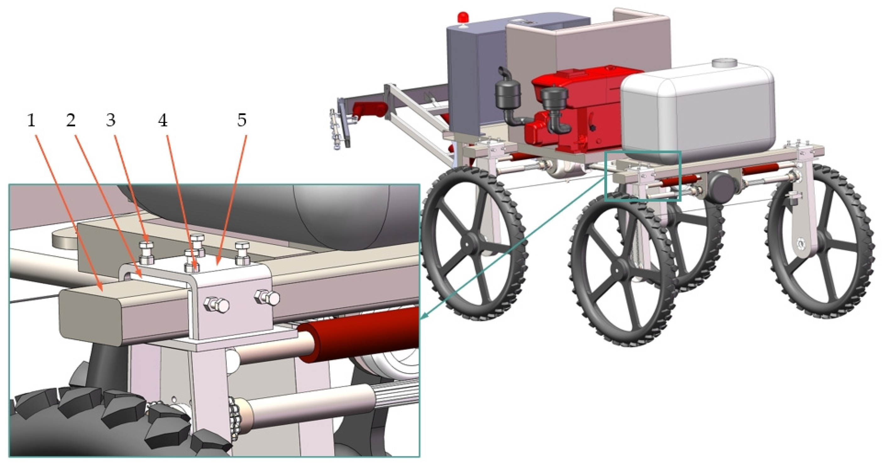
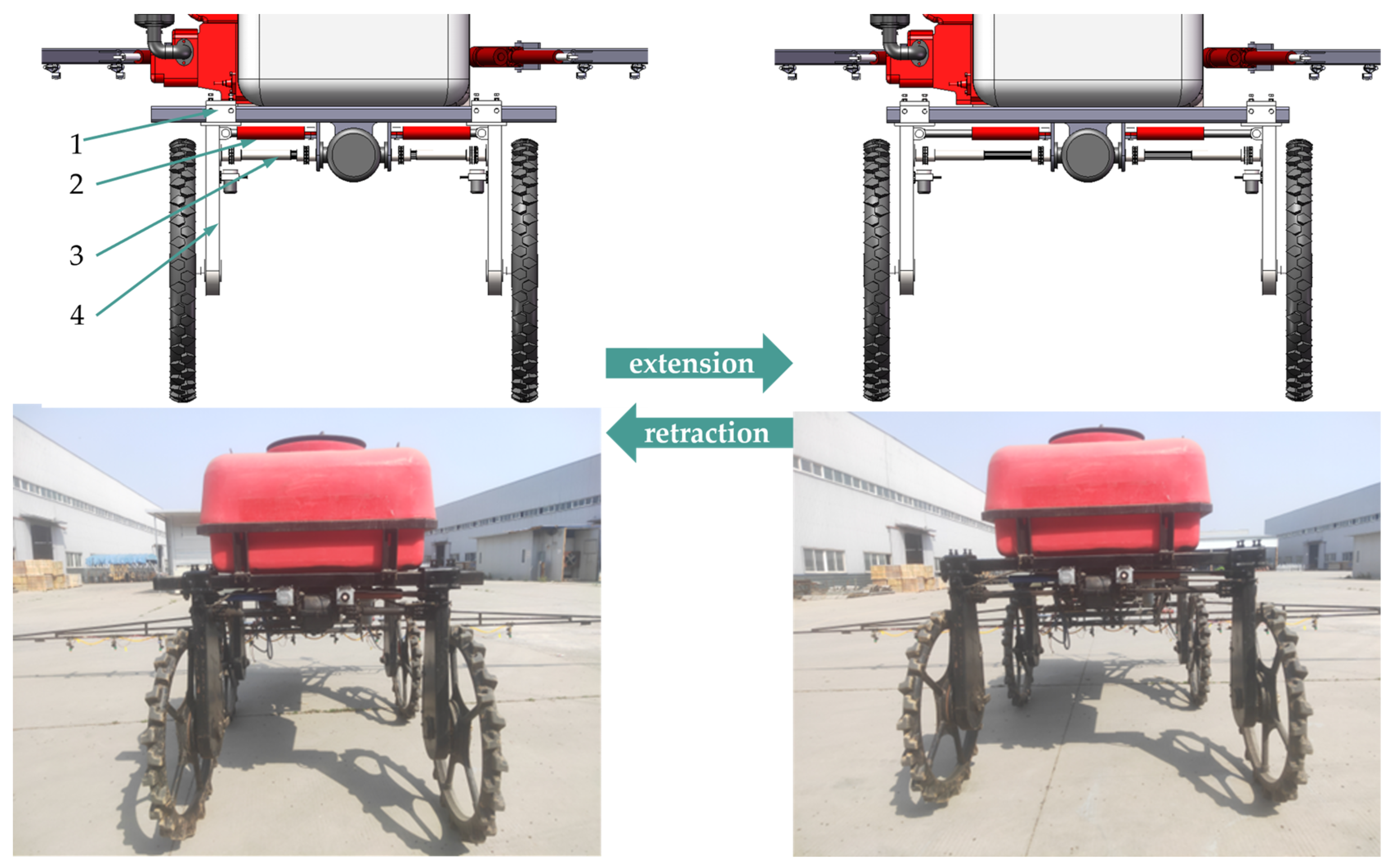
2.2.2. Telescopic Track Width Adjustment Mechanism

Table S1 of the supplementary material presents the row spacing sizes for corn and wheat under different agronomic requirements in Henan Province. Based on the values in the table and considering the need to enhance the maneuverability of the sprayer, this study designed a telescopic track width adjustment mechanism to meet the field management requirements for spanning 7 rows of wheat throughout its growth cycle and 2 rows of corn in the early to mid-growth stages in Henan Province. The adjustable track width parameters range from 1200 to 1600 mm, with a ground clearance of 900 mm.
To enhance the stability of the track width adjustment process and meet road travel requirements, the telescopic adjustment sleeve is employed for track width adjustment. The telescopic track width adjustment mechanism consists of a sprayer crossbeam, adjustment sleeve, sliding bearings, lock nuts, and gap adjustment bolts. Its structure is shown in Figure 4. The movable support wheel frames on both sides are fixedly connected below the adjustment sleeve. The adjustment sleeve and the sprayer crossbeam are connected via sliding bearings. When the adjustment sleeve slides along the crossbeam, the movable support wheel frames move laterally. Due to machining errors and the necessity of assembly clearance, the crossbeam and sliding bearings cannot be in perfect contact. To ensure uniform contact between the sliding bearings and the crossbeam and to reduce tire wobble during track width adjustment, the gap adjustment bolt and lock nut mechanism is used to eliminate the clearance.
As shown in Figure 5, in the hydraulic system, one end of the hydraulic cylinder body is fixedly connected to the sprayer crossbeam, while the piston rod is connected to the movable support wheel frames. During track width adjustment, the electro-hydraulic control system controls the extension and retraction of the hydraulic cylinder, driving the movable support wheel frames on both sides to slide along the direction of the crossbeam, thereby achieving the adjustment of the track width.

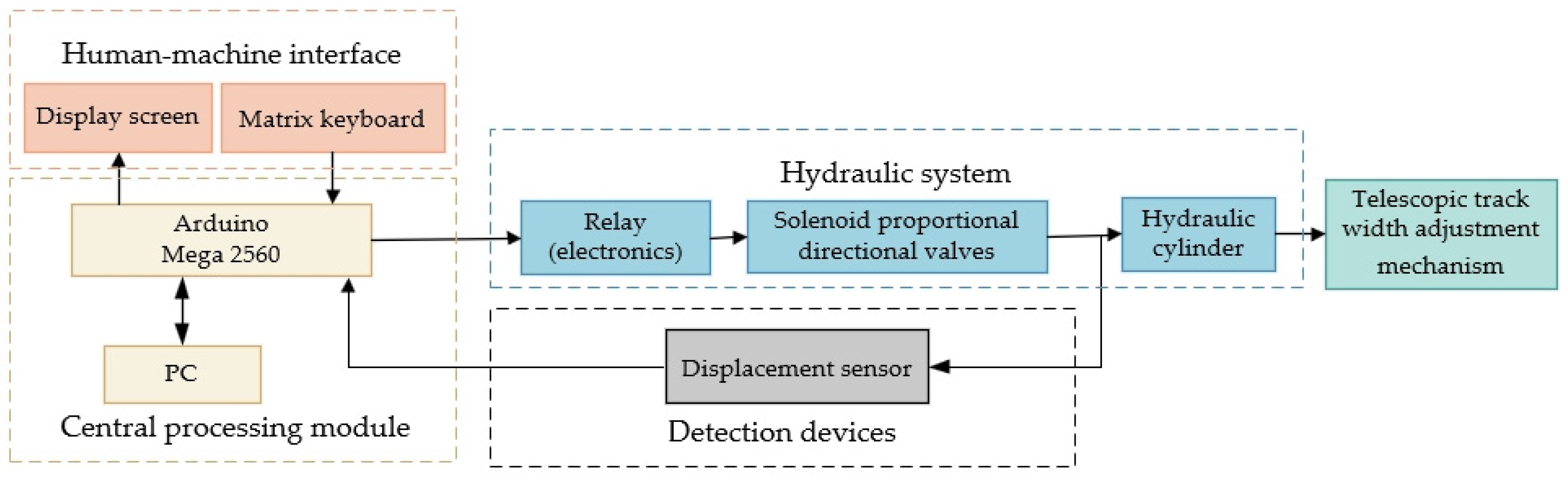
2.3. Electro-Hydraulic Control System

2.3.1. Overall Framework of the Electro-Hydraulic Control System

As shown in Figure 6 and Figure 7, the electro-hydraulic control system comprises the human–machine interface, central processing module, detection devices, and hydraulic system. The human–machine interface, which consists of a display screen and matrix keyboard, is used to input the target track width adjustment value and transmit this signal to the central processing module. The central processing module reads signals from each component, performs calculations, and outputs control signals based on the PWM signal duty cycle to control the actions of the hydraulic system.
The detection devices are used to detect real-time track width information and transmit signals to the central processing module. If the detection devices only measure the overall left and right track width, the wheels on both sides adjust simultaneously during the spacing adjustment process. In this condition, when the overall track width meets the requirements, discrepancies in the hydraulic fluid distribution can lead to inconsistent lateral adjustment distances between the left and right wheels, affecting the stability and operational effectiveness of the sprayer. Therefore, to reduce the error in the track width adjustment between the left and right sides, each wheel is controlled individually, with the detection devices measuring the vertical distance from each wheel to the central axis of the chassis.
The central processing module is the core of the entire electro-hydraulic control system and must be capable of flexible, real-time, and accurate data processing, serial communication, and high reliability. To fulfill the system’s requirement for independent control of four wheels, the MEGA2560 R3, designed by the Italian-origin Arduino (Ivrea, Italy), is utilized. This board features an ATMEGA2560-16AU chip manufactured by Microchip Technology Incorporated in the Chandler, AZ, USA. The detection devices use draw-wire sensors installed inside each movable support wheel frame, with the draw-wire attached to the center of the sprayer crossbeam, and with each draw-wire’s linear motion direction parallel to the crossbeam. Since the track width parameters are adjustable from 1200 mm to 1600 mm, the displacement sensor range must be at least 800 mm. The sensor needs to provide stable, accurate, and timely feedback on the hydraulic cylinder position with millimeter-level precision. Considering these factors and cost, an MPS pulse-type draw-wire displacement sensor was selected.

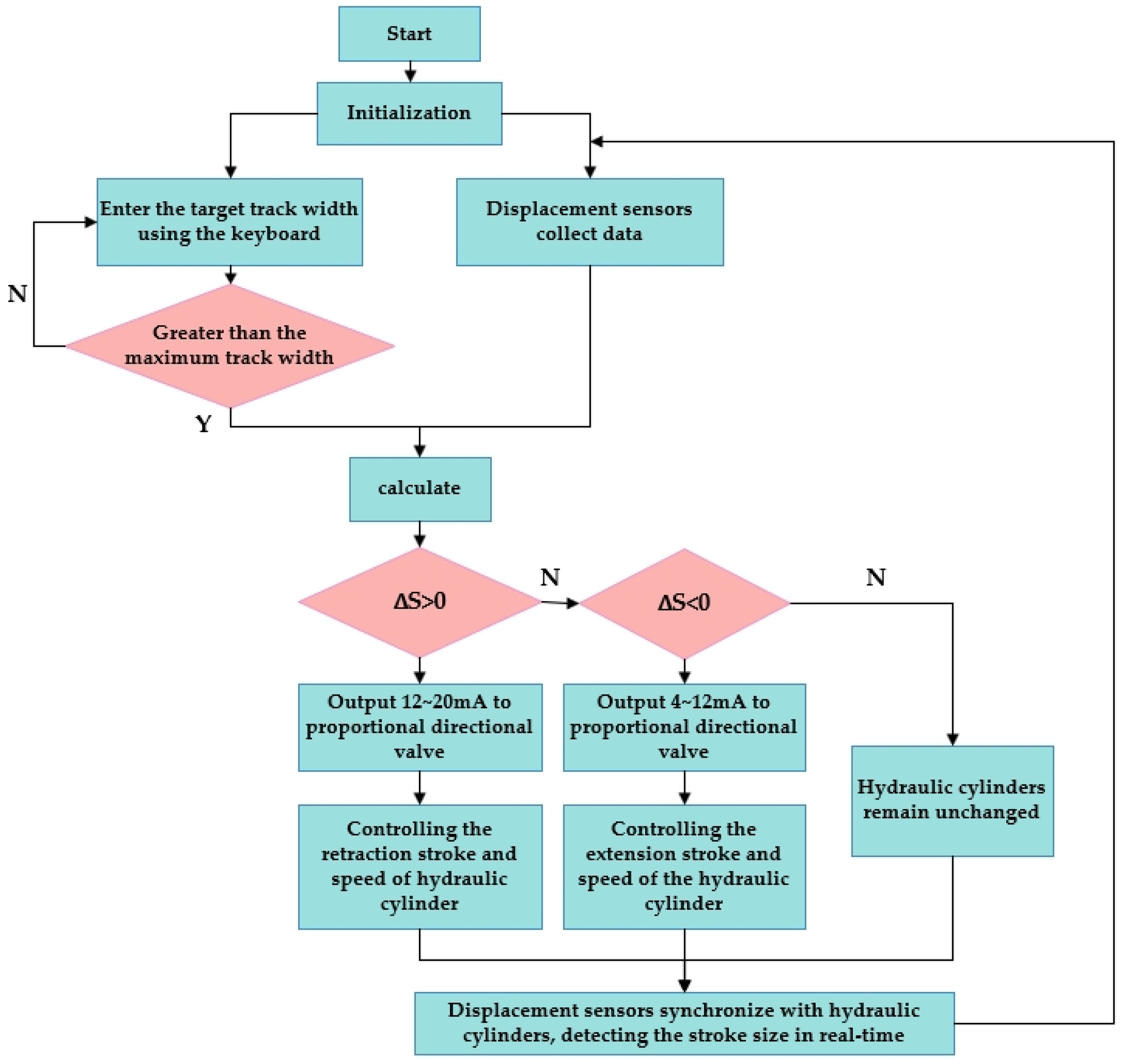
2.3.2. Control System Main Program

The main control program of the system was developed in the Arduino environment using C language. Figure 8 shows the main program flowchart. First, the system powers on and initializes the devices. Initialization involves configuring the input and output pins, setting the initial pin levels, configuring the serial port, and setting up external interrupts for the pins. After initialization, the system enters the main loop, where it first retrieves data from the matrix keypad to set the target track width. The microcontroller uses external interrupts to obtain real-time distance measurements from the draw-wire sensors and compares the received displacement values with the input set values. Through calculations, it generates error signals to select the output channel, essentially determining the stroke and direction of the proportional solenoid valve, thereby altering the flow and direction of hydraulic fluid entering the hydraulic cylinder. An alarm is triggered if the input track width set value exceeds the maximum allowable distance.

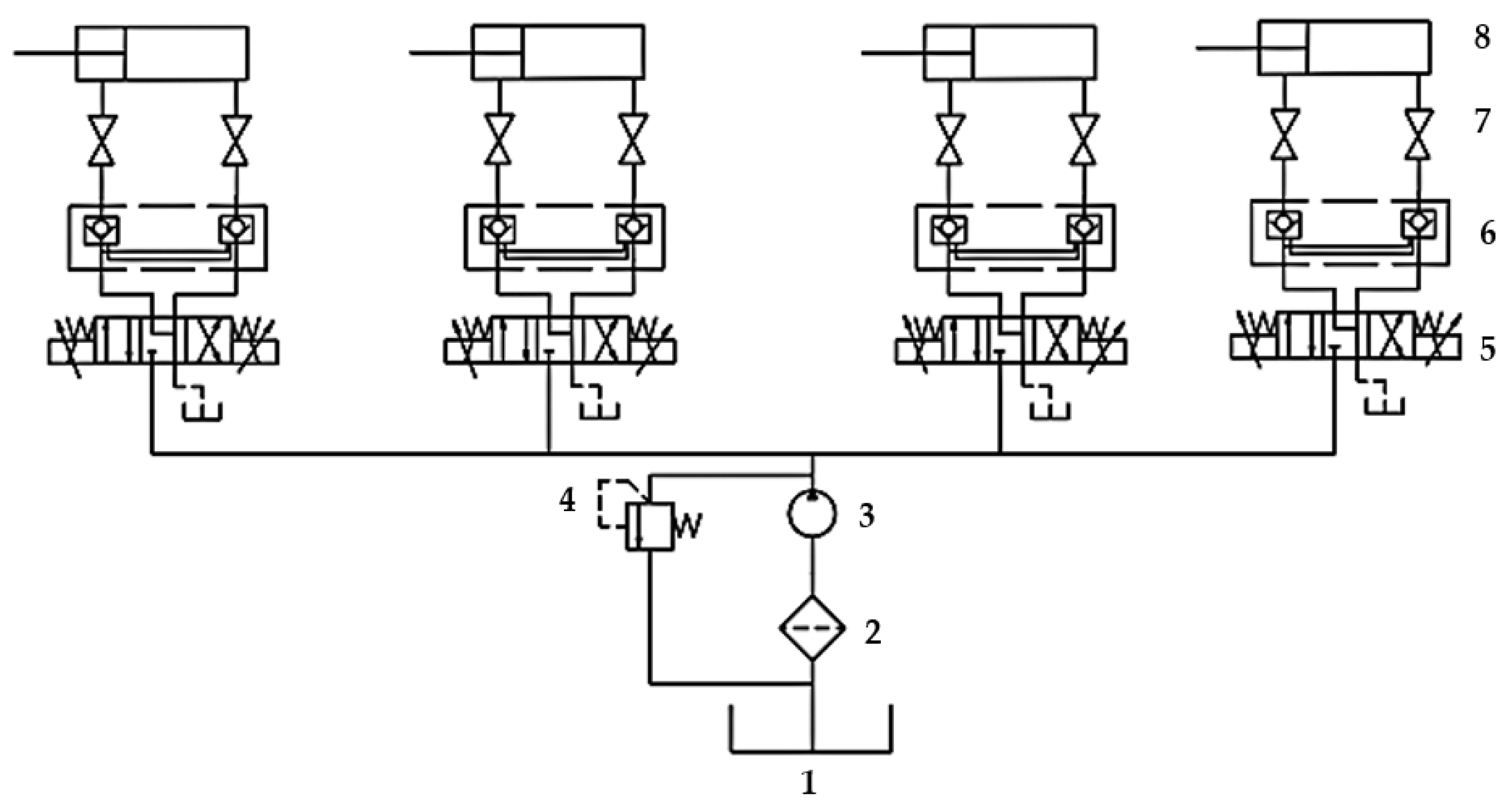
2.3.3. Hydraulic System

  • Principle of the hydraulic system
The hydraulic system primarily consists of an oil tank, solenoid proportional directional valve, hydraulic pump, hydraulic cylinder, engine, bidirectional hydraulic lock, and relief valve, as illustrated in Figure 9. The hydraulic pump, acting as the power source for the hydraulic system, draws in oil, converting low-pressure oil into high-pressure oil. The high-pressure oil exits the hydraulic pump and enters the solenoid proportional directional valve’s inlet. It then passes through the bidirectional hydraulic lock and ball valve before reaching the piston rod side of the hydraulic cylinder, while the oil from the other side of the cylinder flows back to the oil tank [18,19,20,21,22]. To accommodate wide–narrow row seeding, a bidirectional hydraulic lock is incorporated. When the machine is in operation and the solenoid proportional directional valve is in the neutral position, the bidirectional hydraulic lock secures the hydraulic fluid at both ends of the double-acting hydraulic cylinder, maintaining the position of the piston rod and, consequently, the track width.
When the right-side wheel needs to reduce its spacing, the operator inputs the target track width value through the human–machine interface. The controller receives the current track width value detected by the sensor and the target value input from the keyboard. It then calculates the error signal, optimizes the signal using the PID control, and determines the appropriate output channel to control the corresponding solenoid proportional directional valve for the right-side wheel. The solenoid proportional directional valve directs the hydraulic fluid to the right side of the hydraulic cylinder, causing the piston rod to retract to the left, thereby moving the movable support wheel frame leftward and reducing the track width. Once the target distance is reached, the solenoid proportional directional valve resets to the neutral position, allowing the sprayer to operate in the field at the predetermined track width. Conversely, if the right-side track width needs to be increased, the piston rod extends to the right, moving the movable support wheel frame rightward and increasing the track width. Upon reaching the target distance, the solenoid proportional directional valve resets to the neutral position, enabling the sprayer to operate in the field at the specified track width. The same process applies to the left-side wheel.
2.
Design of the hydraulic cylinder
When adjusting the track width, the movable support wheel frame is mainly subjected to the driving force of the hydraulic cylinder piston rod and the friction between the ground and the tire. According to the force–balance relationship, the driving force is equal to the friction force. Therefore, the load on a single hydraulic cylinder satisfies the following equation:
F = 1 4 f G
where f is the friction coefficient between the rubber material of the tire and the ground, with values ranging from 0.5 to 0.7; G is the total weight of the sprayer, N; and F is the load on the hydraulic cylinder, N.
When the sprayer is fully loaded with liquid and the wheelbase is being adjusted, its total weight is approximately 6000 N. Under these conditions, the hydraulic cylinder experiences its maximum load, with f = 0.7 . Substituting these values into Equation (1), the maximum load on the hydraulic cylinder is obtained as F = 1050   N .
According to the hydraulic design manual, the initial system pressure P is selected to be 10 MPa.
The hydraulic cylinder bore diameter D is:
D = 4 F λ π P η m
where η m is the mechanical efficiency of hydraulic cylinders and λ is the hydraulic cylinder round trip speed ratio.
The hydraulic cylinder piston rod diameter d is:
d = D λ 1 λ
Taking η m as 1.33 and λ as 0.9, and substituting the values of F and P into Equations (2) and (3), the calculations yield the hydraulic cylinder bore diameter D and piston rod diameter d . After consulting the hydraulic manual and selecting the appropriate sizes from the GB/T 2348-2018 standard [23], the hydraulic cylinder bore diameter D is determined to be 25 mm, with the piston rod diameter d being 16 mm.
The wheel track adjustment range of the sprayer is from 1200 mm to 1600 mm, so the hydraulic cylinder displacement must exceed 200 mm. Therefore, a hydraulic cylinder stroke of 240 mm is selected.

2.4. Control Scheme Simulation Experiment

In the process of adjusting the track width, the hydraulic system control faces issues such as a significant impact force from the hydraulic cylinders, slow response time, and low control precision. To address these problems, four control strategies are proposed: classical PID, integral separated PID, fuzzy adaptive PID, and integral separated fuzzy PID. Simulations of these four control strategies are conducted using the Simulink tool in MATLAB. Based on the simulation results, the optimal control strategy will be selected.

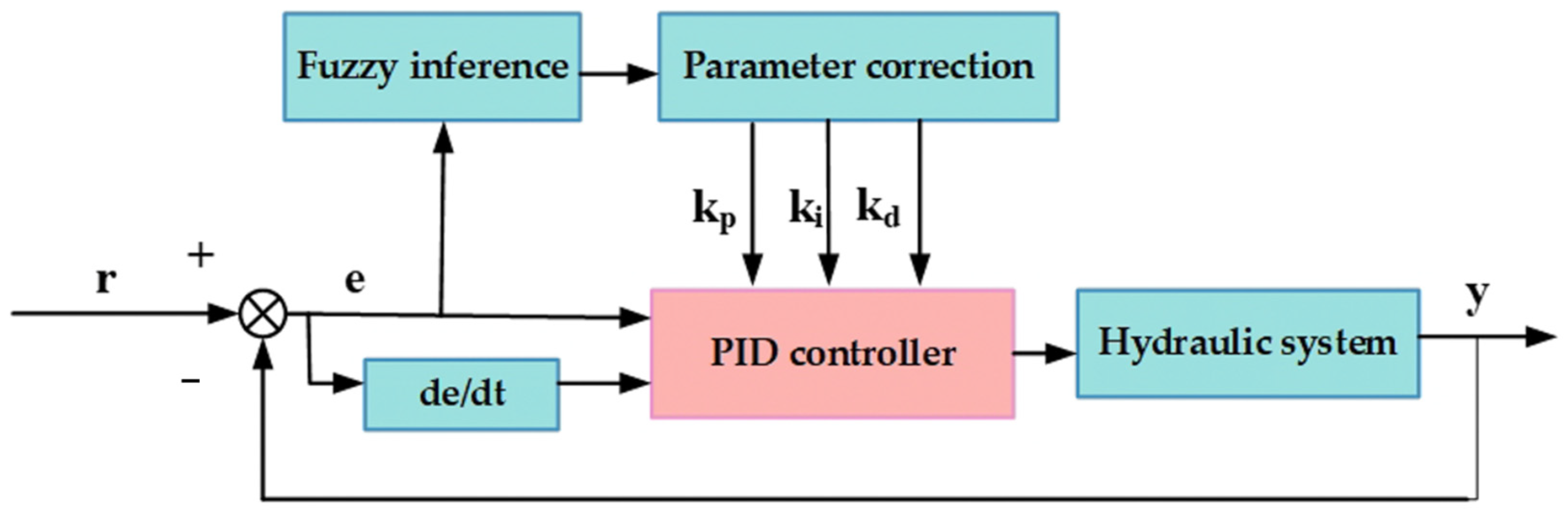
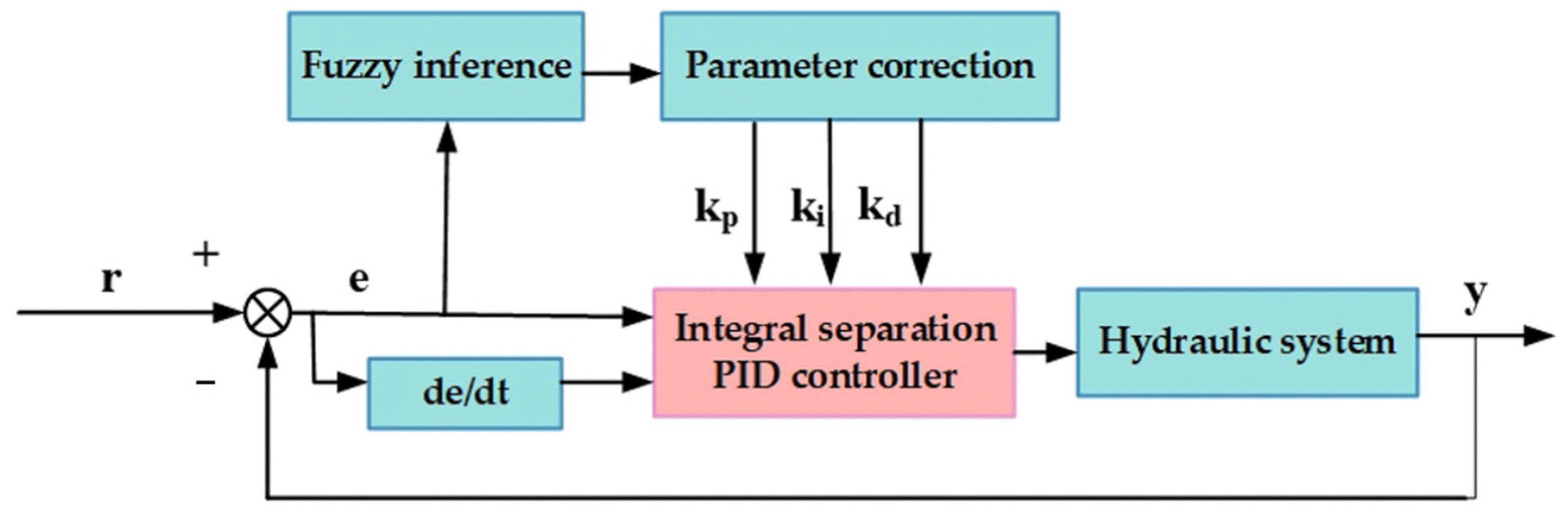
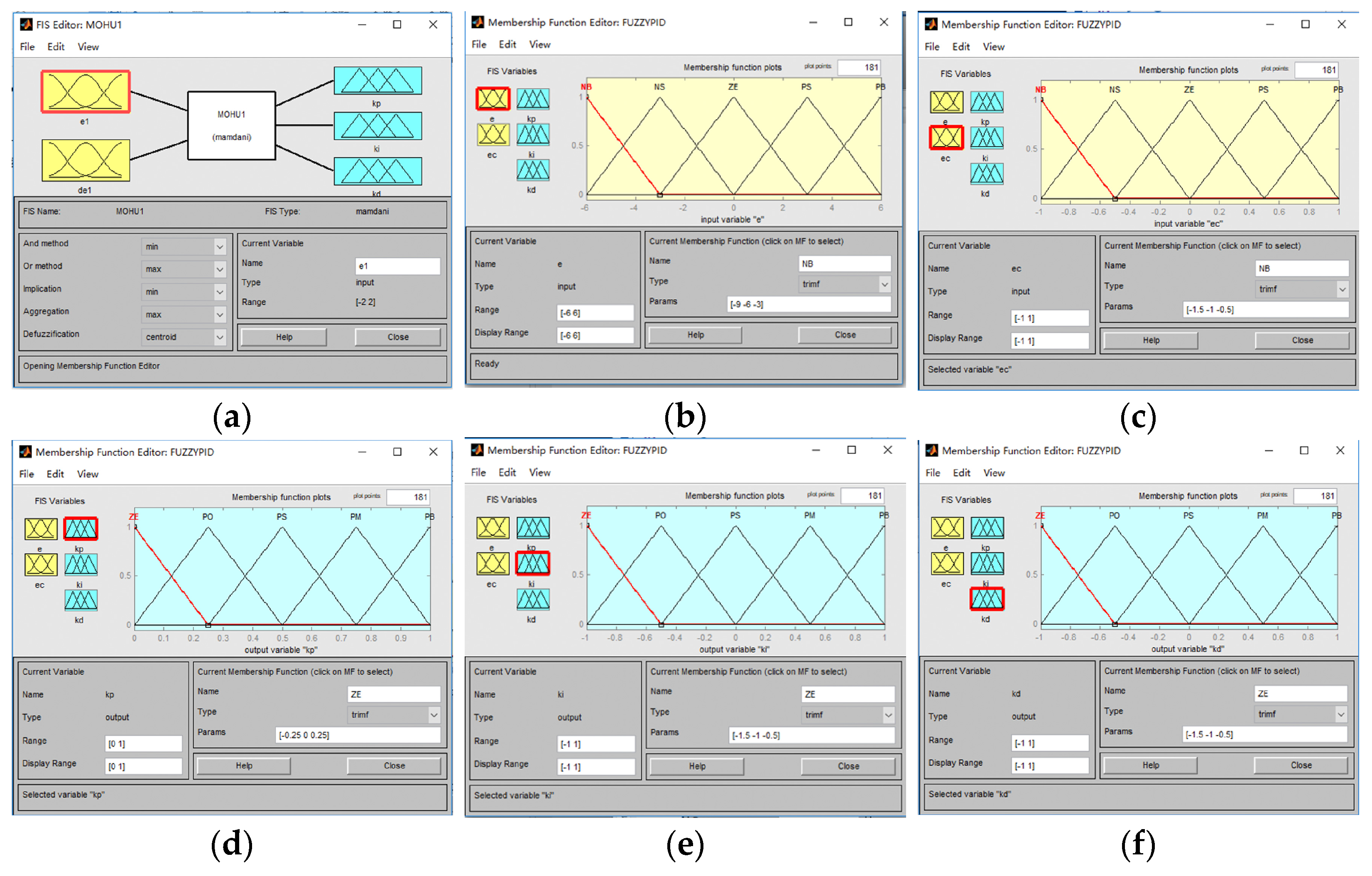
2.4.1. Design of Control Strategies

Considering that the track width is independently controlled by adjusting the four wheels separately, we can focus on simulating the track width variable of a single wheel under different control schemes. The interference between the wheels can be simplified, based on specific working conditions, into a disturbance load torque applied to a single wheel. By designing appropriate controller parameters, this disturbance load torque can be suppressed, enabling the track width control system to meet the desired performance requirements.
Compared to the classical PID control, the integral separated PID control disables the integral action when the deviation between the system output and the target value is large. This prevents excessive overshoot caused by integral accumulation. When the deviation is small, the integral control is introduced to eliminate the steady-state error and improve the control precision [24,25,26,27,28].
The fuzzy adaptive PID control adjusts the parameters of the PID controller in real-time based on fuzzy rule algorithms, adapting to varying working conditions during system operation. This enhances the system’s ability to handle complex scenarios [29,30]. The principles for tuning the fuzzy PID algorithm parameters are as follows: when the absolute value of the deviation e is large and the system is in the response phase, a larger proportional gain Kp is required to speed up the response and prevent a sudden increase in e. To prevent integral saturation, a smaller integral time constant Ti should be used. Additionally, to avoid derivative saturation and prevent significant overshoot in the system response, the influence of the derivative term should be reduced. Figure 10 illustrates the system structure of the fuzzy adaptive PID control.
By combining fuzzy adaptive rules with the integral separated PID control, the integral separated fuzzy PID control scheme is obtained and its system structure is illustrated in Figure 11.

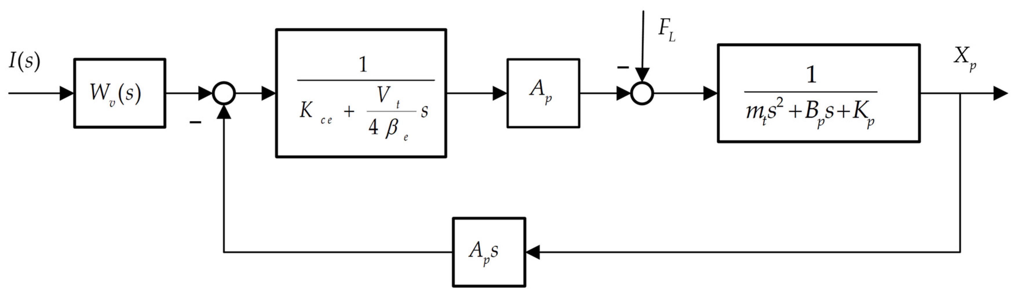
2.4.2. Mathematical Model of Hydraulic System

Before simulating the four control schemes, the mathematical model of the hydraulic system is first constructed using local linearization of the system [31].
  • Mathematical model of hydraulic cylinders
Make the following assumptions:
  • The connecting pipelines between the valve and the hydraulic cylinder are symmetrical, short, and thick, allowing the pressure loss and dynamics within the pipelines to be neglected.
  • The pressure within each working chamber of the hydraulic cylinder is equal.
  • The initial volumes of the oil inlet and return chambers are equal.
  • The oil temperature and bulk modulus are constant.
  • Both internal and external leakage in the hydraulic cylinder are laminar flows.
The simplified flow continuity equation can be obtained as follows:
q L = A p d x p d t + C i p p L + V t 4 β e d p L d t
where A p is the piston area, m2; x p is the piston displacement, m; C i p is the hydraulic cylinder internal leakage coefficient, m3/(Pa·s); β e is the effective bulk modulus of elasticity (including the mechanical flexibility of fluids, connecting pipes and cylinders), Pa; V t = 2 V 0 is the total compressed volume, m3; and p L is the pressure in the low-pressure chamber (return chamber) of the hydraulic cylinder, Pa.
2.
Mathematical model of solenoid proportional directional valve
The model of an electro-hydraulic proportional directional valve primarily involves the flow-pressure equations of the valve ports. Here, q 1 and q 2 represent the flow rates entering the high-pressure chamber and low-pressure chamber of the motor through the servo valve, respectively. p 1 and p 2 are, respectively, the pressures in the high-pressure and low-pressure chambers of the motor. p s and p e are, respectively, the supply pressure and return pressure. x s p represents the displacement of the spool of the electro-hydraulic proportional valve.
q 1 = C d w x s p 2 ρ p s p 1 q 2 = C d w x s p 2 ρ p 2 p e                     x s p > 0
q 1 = C d w x s p 2 ρ p 1 p e q 2 = C d w x s p 2 ρ p s p 2                     x s p < 0
To improve simulation efficiency, the linearization method is used to further simplify Equations (5) and (6). Assuming the valve is a zero-lapped four-way spool valve, with four matched and symmetrical throttle windows, constant supply pressure p s , and zero return pressure p 0 , the linearized flow equation for the zero-lapped four-way spool valve is given by:
q L = K q x v K c p L
The dynamic analysis of position servo systems is often conducted under zero-displacement operating conditions, where the increments and variables are equal. For a matched and symmetric zero-lapped four-way sliding valve, the flow q 1 and q 2 through both control channels is equal to the load flow q L . During dynamic analysis, it is essential to consider the impact of the external leakage and compressibility of the hydraulic cylinder, which results in the inflow and outflow rates of the hydraulic cylinder being unequal. To simplify the analysis, the load flow is defined as:
q L = q 1 + q 2 2
Consider an electro-hydraulic proportional valve with the current Δ i as the input parameter and the no-load flow rate q 0 = K q x v as the output parameter. In most electro-hydraulic proportional systems, the dynamic response of the proportional solenoid valve is often higher than that of the power components. In this context, the transfer function of the proportional solenoid valve can be represented by a second-order oscillatory system:
W s v s = Q 0 Δ I = K s v s 2 ω s v 2 + 2 ζ s v ω s v s + 1
where K s v is the flow gain of the solenoid proportional valve, m2/s; ω s v is the inherent frequency of the solenoid proportional valve, rad/s; and ζ s v is the damping ratio of the solenoid proportional valve.
3.
Mathematical model of solenoid proportional directional valve controlled hydraulic cylinder system
Based on the force balance equation, the linearized equations of the hydraulic cylinder and the electro-hydraulic proportional valve are combined to form the mathematical model of the valve-controlled hydraulic cylinder system:
A p p L = m t d 2 x p d t 2 + B p d x p d t + K p x p + F L
where m t is the total mass of the piston and load converted to the piston, kg; B p is the viscous damping coefficient of the piston and load, N·s/m; K p is the load spring stiffness, N/m; and F L is the external load force, N.
Performing the Laplace transform of Equations (4), (7) and (10):
Q L = K q X v K c P L  
Q L = A p s X p + C i p P L + V t 4 β e s P L
A p p L = m t s 2 X p + B p s X p + K p X p + F L
The transfer function block diagram is obtained as shown in Figure 12.
As shown in Table S2 of the supplementary material, the parameters for each hydraulic component were configured, and the values were incorporated into the aforementioned control block diagram. This process yielded the mathematical model presented in Equation (14).
W s v s = 0.00013 s 2 200 2 + 1.414 s 200 + 1

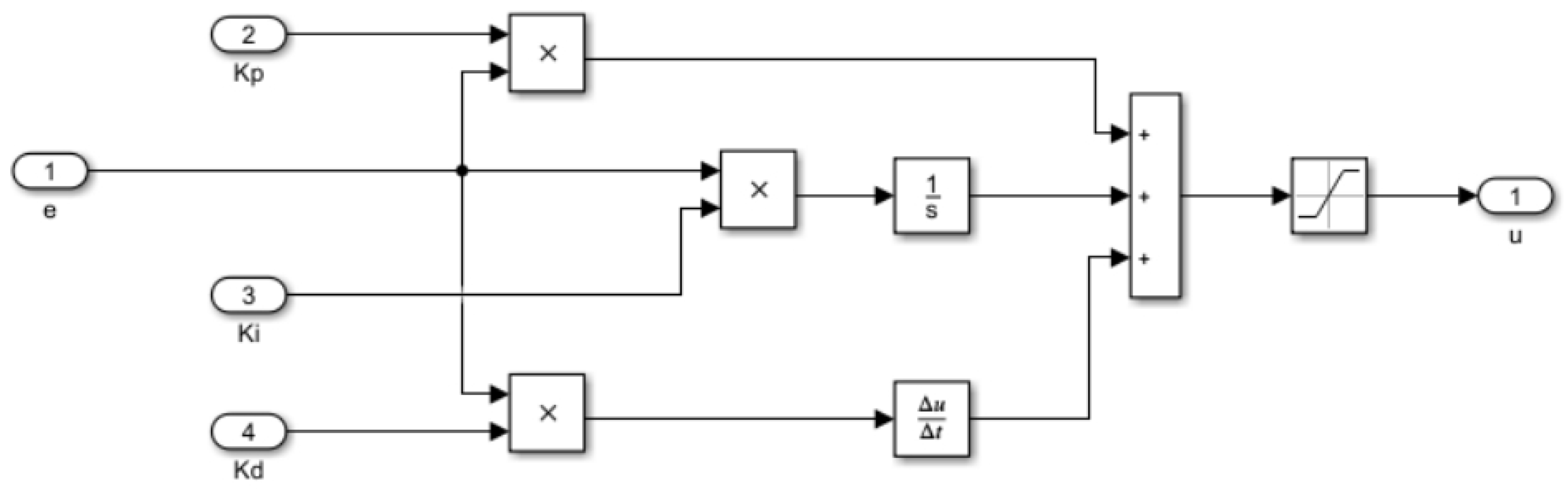
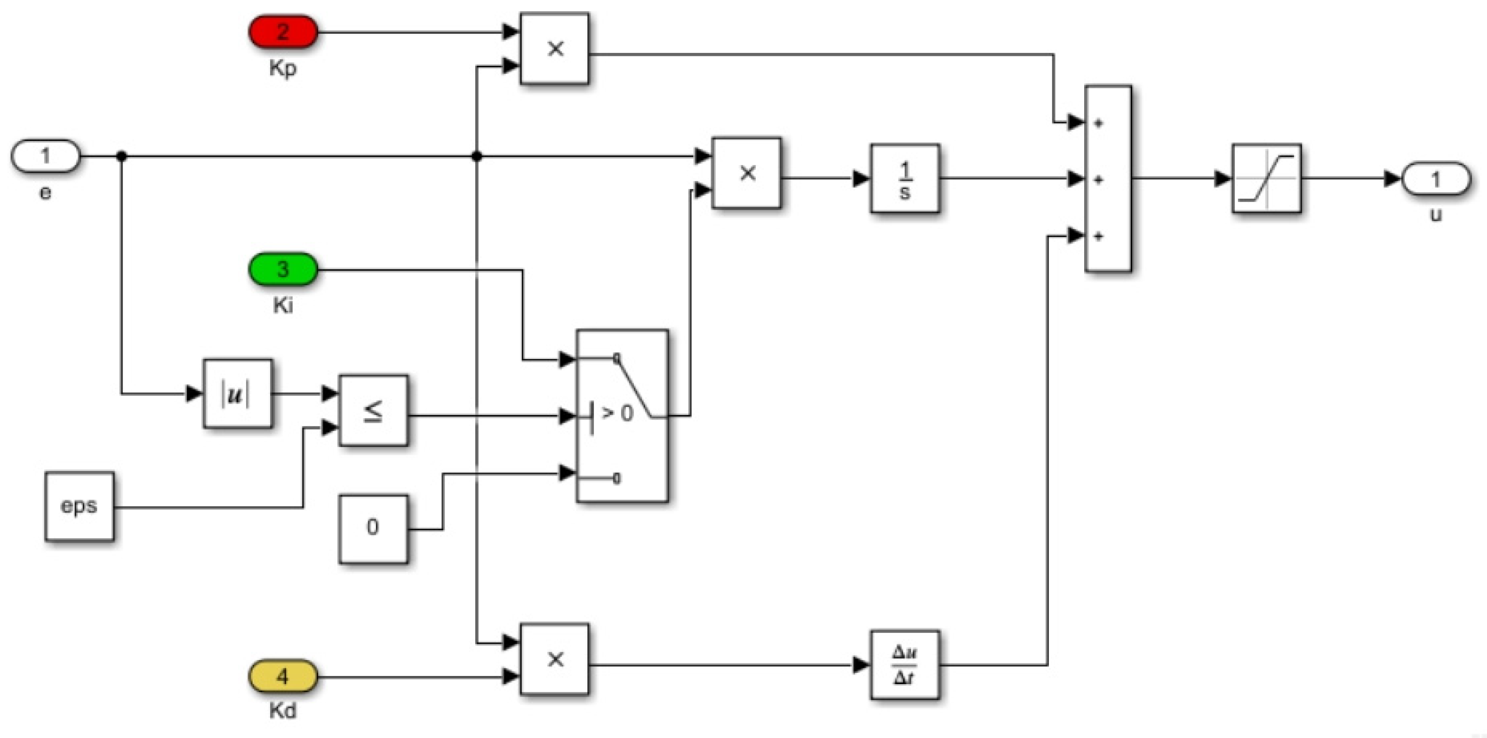
2.4.3. Construction of Simulation Models for Control Schemes

Based on the transfer function models of the main components in the hydraulic cylinder system controlled by the proportional valve, four control scheme models were constructed in Simulink. The same PID parameters (Kp = 1.5, Ki = 2, Kd = 0) were set for the simulation experiments. The construction of the classical PID and the integral separated PID models is relatively straightforward and is not described in detail in this paper. Figure 13 and Figure 14 show, respectively, the simulation models of the classical PID and the integral separated PID.
The design diagram of the fuzzy controller is shown in Figure 15a. Firstly, the range of the input variable e is set to [−6, 6], and the range of the input variable ec is set to [−1, 1]. Both variables e and ec include the NB, NS, ZE, PS, and PB. Secondly, the output variable Kp is set with a range of [0, 1]. The output variables Ki and Kd are both set with a range of [−1, 1]. These three output variables also include ZE, PO, PS, PM, and PB.
Based on the fuzzy PID rules, the output variable values are calculated. They are created and stored in real-time on the computer in the form of a lookup table. By directly querying the output table values with the fuzzy linguistic variables of error e and error change ec, the PID increment values are obtained. The controller model constructed in Simulink is shown in Figure 16.
Figure 17 illustrates the real-time adjustment of the three controller data. It can be observed that the fuzzy rules effectively adjust the proportional and integral coefficients during the initial stage, while the adjustment of the differential coefficient is relatively minor. This indicates that the track width control system primarily achieves an input signal tracking response through the proportional integral controller. Figure 18 shows the input–output surface view of the fuzzy inference system.
Combining the fuzzy adaptive rule with the integral separated PID controller, the integral separated fuzzy PID control scheme model was constructed in Simulink, as shown in Figure 19. In this model, the part combining the integral separated PID and fuzzy control is encapsulated within the Subsystem module.
Taking the scenario of increased track width as an example, the simulation was conducted where the displacement of the single-side track width was adjusted from 600 mm to 800 mm, corresponding to a hydraulic rod stroke adjustment from 0 to 200 mm. A step signal was input to simulate the track width adjustment process, with the step signal trigger time set to 0 s.

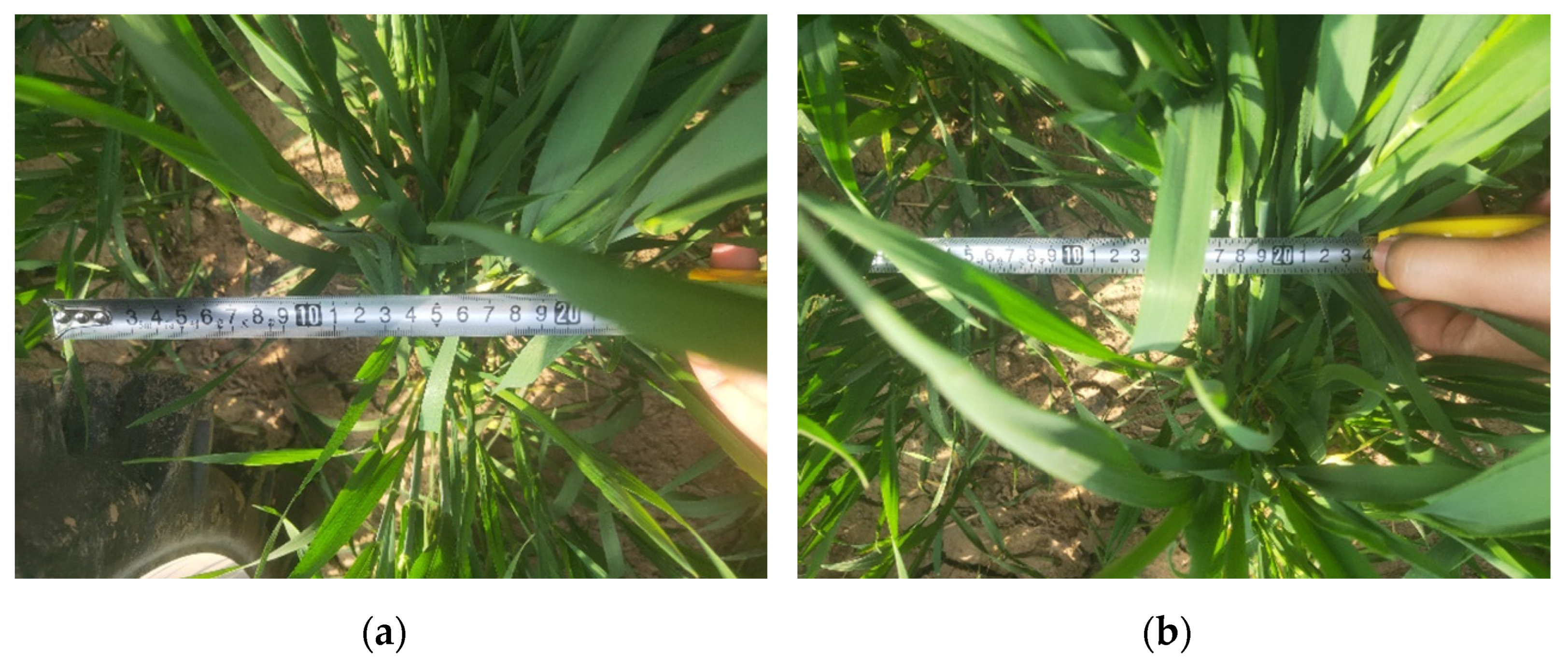
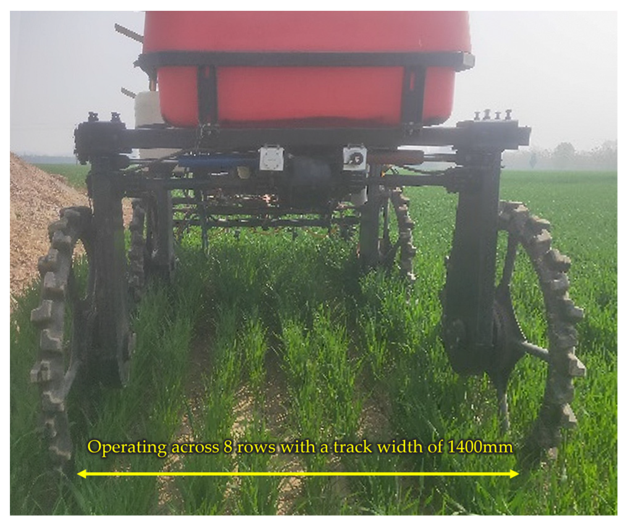
2.5. Field Performance Experiment

2.5.1. Description of the Field Experiment Area

A stability and precision test for row spacing adjustment was conducted in a wheat field in Wuzhi County, Henan Province. The wheat plants were approximately 20 to 40 cm tall. As shown in Figure 20, the experimental wheat field utilized wide–narrow row seeding, with a wide row spacing of 20 cm and a narrow row spacing of 15 cm. The field surface was level, and the soil was relatively loose.

2.5.2. Experimental Treatments

  • Track Width Adjustment Stability Experiment Treatment
Prior to the experiment, the sprayer was adjusted to 1400 mm (spanning 8 rows of wheat). During the experiment, the operator controlled the sprayer speed at 0.5 m/s, maintaining a track width of 1400 mm while navigating the field. A measuring tape was used to measure the track width at 1 m intervals along the sprayer’s operating path, resulting in 20 sets of actual track width data.
2.
Track Width Adjustment Precision Experiment Treatment
To verify the precision of row spacing adjustment, an error analysis was conducted for the process of adjusting the sprayer track width from 1400 mm to 1550 mm (from 8 rows to 9 rows) and from 1550 mm to 1400 mm (from 9 rows to 8 rows). During the experiment, the operator set the target track width via the human–machine interface and controlled the sprayer speed at 0.5 m/s. A measuring tape was used to measure the track width at 1 m intervals along the sprayer’s operating path.
When the relative errors between the measured track widths for five consecutive times and the target track width were less than the stability coefficient obtained from the stability test, the sprayer was considered to have achieved the predetermined track width. At this point, the average of these five track width measurements was taken as the final track width adjustment value of the sprayer. The adjustment process from 8 rows to 9 rows and from 9 rows to 8 rows was each repeated six times in the same field plot. Figure 21 illustrates the experimental process.

3. Results and Discussion

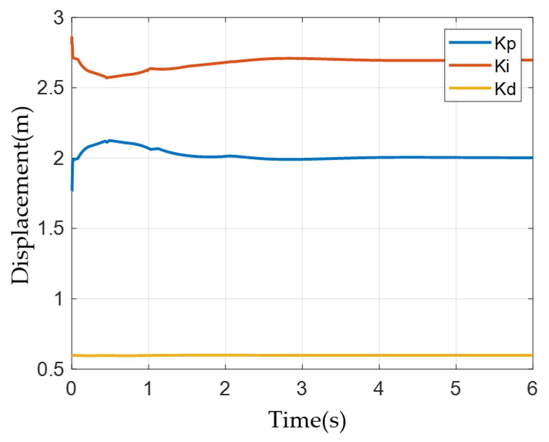
3.1. Simulation Experiment Data Collection and Analysis

The hydraulic cylinder displacement response curves for four different control schemes were obtained through simulation, as shown in Figure 22.
From the figure, it can be observed that under a given input of 800 mm, the classic PID control strategy exhibits the highest overshoot. This occurs because when the system starts or undergoes significant changes in the target value, the system experiences a substantial deviation in a short period. This deviation causes an accumulation in the integral calculation of the PID operation, resulting in a particularly large output and significant system oscillations.
In comparison to the classic PID control strategy, the integral-separated PID control strategy exhibits a smaller overshoot. This improvement is attributed to the addition of a gating switch in the integral-separated PID control, which turns off the integrator when the deviation exceeds a set threshold.
The fuzzy adaptive PID, relative to the classic PID control strategy, shows improvements in both overshoot and settling time due to its capability to adjust the PID controller parameters in real-time based on system conditions.
The integral separated fuzzy PID control strategy achieves a rapid response speed and the smallest overshoot. This control strategy can achieve the desired track width within 2.08 s, maintaining an overshoot of around 2.37%, effectively reducing the number of oscillations and achieving high steady-state accuracy. The integral separated fuzzy PID control strategy reduces overshoot by weakening the integral term in the presence of large system deviations. Additionally, the inclusion of fuzzy control allows for further fine-tuning of control parameters, optimizing performance beyond the basic configuration. Thus, it demonstrates superior control performance compared to the other three strategies.
Therefore, the integral separated fuzzy PID control strategy is confirmed as the optimal control scheme for the track width adjustment system.

3.2. Track Width Adjustment Stability Experiment Data Collections and Analysis

Processing the data from the 20 groups in Figure 23 yields an average actual track width of 1398.05 mm with a standard deviation of 42.50 mm. According to Equation (15), the calculated track width stability coefficient is 3.04%, which is below the threshold of 10%. This indicates that the track width adjustment system is relatively stable and meets the standards for agricultural machinery and agronomic requirements.
V = S a × 100 %
where S is the standard deviation of track width, mm; a is the average track width, mm; and V is the track width stability coefficient.

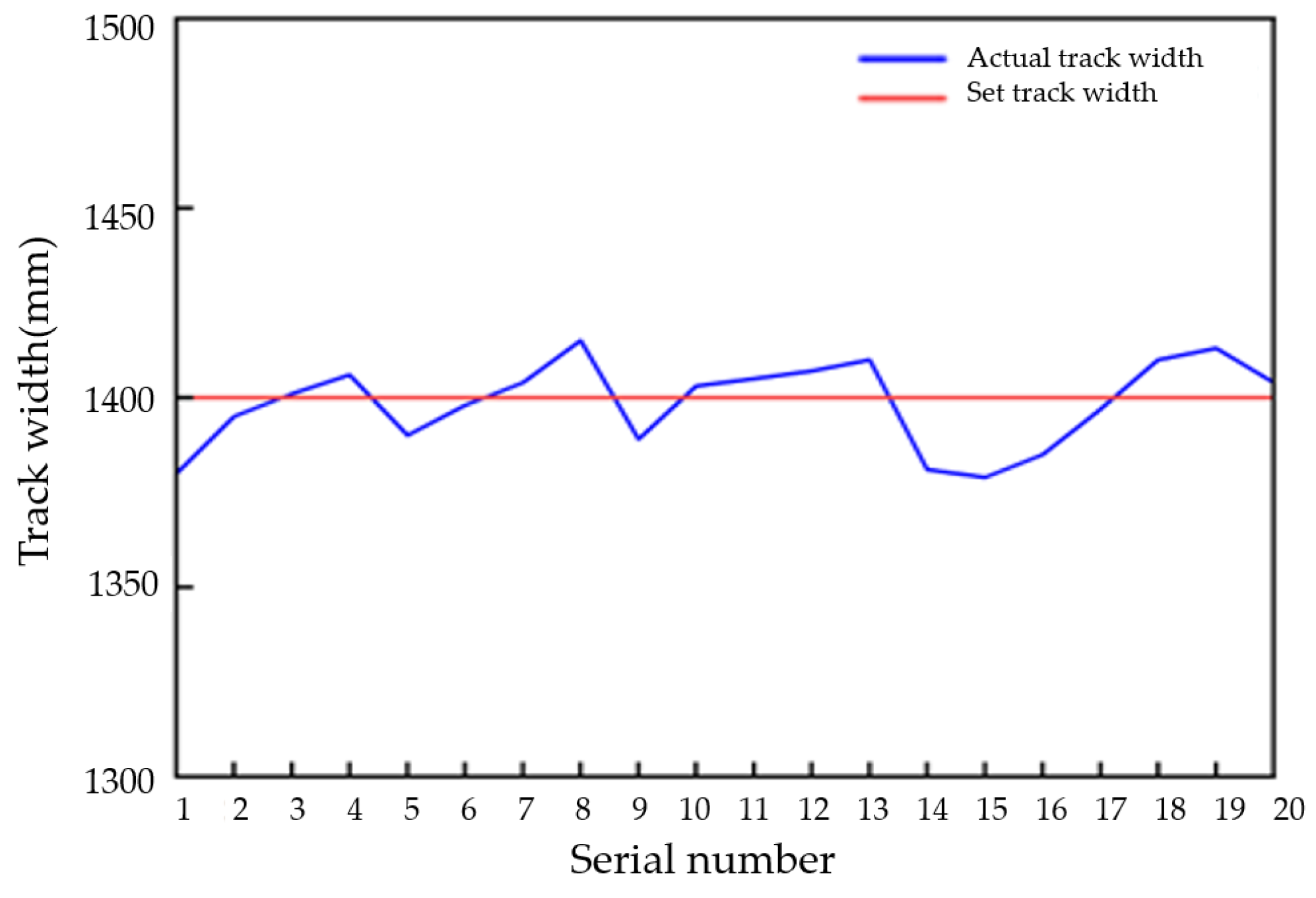
3.3. Track Width Adjustment Precision Experiment Data Collections and Analysis

Table 1 presents the experimental data on track width adjustment errors. A comparative analysis between the final track width adjustment values of the sprayer and the target track width values reveals that the track width adjustment errors are all within 21 mm or less, with an average error of 13.42 mm. The accuracy of the track width adjustment is relatively high.

4. Conclusions

To improve the adaptability of the sprayer to different operating conditions, reduce crop damage, and enhance the stability and accuracy of the track width adjustment, this paper employed electro-hydraulic control technology to design a track width adjustment system for sprayers based on an integral separated fuzzy PID control strategy.
The designed track width adjustment system consists of a transmission mechanism, a telescopic track width adjustment mechanism, and an electro-hydraulic control system. By analyzing the agronomic requirements for field management during the early growth stages of corn and throughout the growth stages of wheat in Henan Province, China, the key parameters for the track width adjustment mechanism were determined. The focus was on designing the electro-hydraulic control system, which comprises a human–machine interface, a central processing module, detection devices, and a hydraulic system. Four control strategies were proposed: classic PID, fuzzy adaptive PID, integral separated PID, and integral separated fuzzy PID. Simulink was used to simulate these control strategies, and the results indicated that the integral separated fuzzy PID control strategy was the most effective, significantly reducing system oscillations, improving the response speed, and enhancing the track width adjustment accuracy. Field test results showed that the stability difference coefficient of the track width adjustment system was 3.04%, which is below the 10% agricultural machinery standard. The average error during track width adjustment was 13.42 mm, demonstrating high accuracy.
The findings of this study provide a research foundation for the development of a more intelligent, precise, and stable track width variable chassis for sprayers and other agricultural machinery. Future efforts should focus on further field testing and system optimization to enhance the stability and reliability of track width adjustments. Additionally, integrating image sensors to collect real-time data on crop row spacing for comparisons with the track width adjustments would enable automatic adjustment to the optimal track width.

Supplementary Materials

The following supporting information can be downloaded at: https://www.mdpi.com/article/10.3390/agriculture14081247/s1, Table S1. Agronomic requirements for corn and wheat; Table S2. Parameter setting for each hydraulic component.

Author Contributions

Conceptualization, L.T., M.J. and J.H.; Funding acquisition, J.H.; Methodology, L.T. and M.J.; Software, M.J.; Validation, L.T., X.S. and H.L.; Writing—original draft, L.T.; Writing—Review and editing, J.H., Q.W. and H.Y. All authors have read and agreed to the published version of the manuscript.

Funding

This research was funded by the National Key R&D Program of China no. 2022YFD1500704-1.

Institutional Review Board Statement

Not applicable.

Data Availability Statement

The data that support the findings of this study are available from the corresponding author upon reasonable request.

Conflicts of Interest

The authors declare no conflicts of interest.

References

  1. National Bureau of Statistics of China. China Statistical Yearbook-2023; China Statistics Press: Beijing, China, 2023. [Google Scholar]
  2. Shen, Z.; Han, T.F. Temporal and spatial variability of relative yield differences between wheat and maize and their response to nitrogen fertilizer. Chin. J. Agric. Sci. 2023, 56, 2724–2737. [Google Scholar]
  3. Zheng, R.J.; Luan, L. Application of boom sprayers in the control of diseases, pests, and weeds in Rice-Wheat rotation Areas. Mod. Agric. Sci. Technol. 2023, 15, 99–103. [Google Scholar]
  4. Sun, W.F.; Liu, H.Y. Design and experiment of PID control variable spraying system based on neural network tuning. Trans. Chin. Soc. Agric. Mach. 2020, 51, 55–64+94. [Google Scholar]
  5. Zhou, Z.Y.; Zhou, M.J. Research on automatic leveling control system of boom sprayer with rotor suspension. Trans. Chin. Soc. Agric. 2022, 53, 70–79. [Google Scholar]
  6. Xu, Y.D.; Liu, G.H. Four-wheel synchronous steering sprayer tracking control based on fuzzy MPC. Control Eng. 2024, 1–9. [Google Scholar] [CrossRef]
  7. Wan, T.; Wang, W.J. Development research and analysis of variable chassis technology for agricultural tractors. Tractor Farm Transp. 2020, 47, 4–6. [Google Scholar]
  8. Zuo, Z.J. Research and Design of Variable Ground Clearance and Track Width Tractor Chassis. Master’s Thesis, Shandong University, Jinan, China, 2016. [Google Scholar]
  9. Case New Holland. Case “Patriot” Patriot~(TM) 3230 sprayer, powerful. Agric. Mach. 2020, 4, 29. [Google Scholar]
  10. Zhang, Q. Stability Study of Variable Track Power Platform in Hilly and Mountainous Areas. Master’s Thesis, Xihua University, Chengdu, China, 2023. [Google Scholar]
  11. Liu, D.X.; Qi, J.H. Multifunctional Self-Propelled Adjustable Boom Spraying Detasseling Machine. Siping, China, 2015. Available online: http://search.cnipr.com/search!doDetailSearch.action (accessed on 25 July 2024).
  12. Wang, M.; Xie, F. Current development status of plant protection spraying devices in China. Agric. Eng. 2019, 9, 4–7. [Google Scholar]
  13. Li, J. Design of an Agricultural Variable Wheelbase Electric Mobile Platform. Master’s Thesis, Chongqing Three Gorges University, Chongqing, China, 2021. [Google Scholar]
  14. Xia, J.L.; Guan, C.S. A Device for Adjusting the Rear Wheel Spacing of a Wheeled Tractor. Yancheng, China, 2014. Available online: http://search.cnipr.com/search!doDetailSearch.action (accessed on 25 July 2024).
  15. Chipriana, A.A.; Puig Mauri, O.C. Equips para la mechanization del cultivate explanations frustules de Alta densipan. Investig. Agrar. Prod. Prot. 2000, 15, 125–142. [Google Scholar]
  16. Blanco, M.N.; Michael, R.A. Real-time monitoring of spray drift from three different orchard sprayers. Chemosphere 2019, 222, 46–55. [Google Scholar] [CrossRef] [PubMed]
  17. Zhang, X.; Xie, Y. Machine Vision-Based Obstacle Avoidance Hydraulic Chassis with Variable Wheel Track and Its Usage Method. 2018. Available online: http://search.cnipr.com/search!doDetailSearch.action (accessed on 25 July 2024).
  18. Wang, X.C.; Shang, Z.G. Current research status and development trends of plant protection machinery design and manufacturing technology. Mod. Agric. Sci. Technol. 2017, 2, 282–288. [Google Scholar]
  19. Huang, M.; Zheng, D.K. Synchronization study of sugarcane cultivator with rhombic self-propelled chassis based on AMESim. J. Agric. Mech. Res. 2017, 39, 7–12. [Google Scholar]
  20. Dou, L.J. Design and Research of Adjustable Track Steering System for High-Clearance Self-Propelled Sprayer. Master’s Thesis, Chinese Academy of Agricultural Mechanization Sciences, Beijing, China, 2012. [Google Scholar]
  21. Fan, G.Q.; Meng, X.G. Agricultural High-Clearance Operation Machine. 2015. Available online: http://search.cnipr.com/search!doDetailSearch.action (accessed on 25 July 2024).
  22. Cui, Y.J.; Zhang, Z.L. Kinematic simulation analysis of fruit picking manipulator based on ADAMS. J. Agric. Mech. Res. 2008, 4, 59–61. [Google Scholar]
  23. GB/T 2348-2018; Fluid Power Systems and Components—Cylinder Bores and Piston Rod Diameters. Standardization Administration of China: Beijing, China, 2018.
  24. Kwok, K.E.; Chong, P.M. A model based augmented PID algorithm. J. Process Control 2000, 10, 9–18. [Google Scholar] [CrossRef]
  25. Xue, D.Y. Control System Computer-Aided Design—MATLAB Language and Application; Tsinghua University Press: Beijing, China, 1996. [Google Scholar]
  26. Liu, J.K. Advanced PID Control and Simulation; Electronics Industry Press: Beijing, China, 2000; pp. 1–8. [Google Scholar]
  27. Qiu, L.; Zeng, G.E. Comparative study on several PID controller parameter tuning methods. Autom. Technol. Appl. 2005, 24, 28–31. [Google Scholar]
  28. Han, P.P. Research and Design of Fuzzy Self-Tuning PID Controller. Master’s Thesis, Hebei University of Technology, Tianjin, China, 2010. [Google Scholar]
  29. Sun, C.Y. Principles and Design of Measurement and Control Systems; Beijing University of Aeronautics and Astronautics Press: Beijing, China, 2003; pp. 160–166, 174. [Google Scholar]
  30. Zhao, H.Q. Rapid empirical tuning method for PID control parameters. Chem. Ind. Autom. Instrum. 1997, 24, 43–45. [Google Scholar]
  31. Liu, J.Q.; Ding, P. Research on remote steering system of tractor based on fuzzy PID control. J. Agric. Mech. 2024, 1–8. [Google Scholar] [CrossRef]
Figure 1. Overall structure of the track width adjustment system. 1—telescopic track width adjustment mechanism; 2—electro-hydraulic control system; 3—transmission mechanism.
Agriculture 14 01247 g001
Figure 2. Schematic diagram of the drive shaft assembly. 1—differential; 2, 5—double-row chain coupling; 3—splined driving shaft; 4—splined driven shaft sleeve; 6—sprocket box input shaft.
Agriculture 14 01247 g002
Figure 3. Schematic diagram of the wheel-side drive components. 1—sprocket box output shaft; 2—sprocket chain; 3—sprocket box input shaft.
Agriculture 14 01247 g003
Figure 4. Telescopic track width adjustment mechanism. 1—sprayer crossbeam; 2—sliding bearings; 3—gap adjustment bolts; 4—lock nuts; 5—adjustment sleeve.
Agriculture 14 01247 g004
Figure 5. Track width adjustment process. 1—telescopic track width adjustment mechanism; 2—electro-hydraulic control system; 3—transmission mechanism; 4—the movable support wheel frame.
Agriculture 14 01247 g005
Figure 6. Overall structure of electro-hydraulic control system. Note: The central processing module is an Arduino Mega 2560 development board.
Agriculture 14 01247 g006
Figure 7. Overall framework of the electro-hydraulic control system.
Agriculture 14 01247 g007
Figure 8. The main program flowchart.
Agriculture 14 01247 g008
Figure 9. Schematic diagram of the hydraulic system. 1—oil tank; 2—filtering apparatus; 3—hydraulic pump; 4—relief valve; 5—solenoid proportional directional valve; 6—bidirectional hydraulic lock; 7—ball valves; 8—hydraulic cylinder.
Agriculture 14 01247 g009
Figure 10. System structure of the fuzzy adaptive PID control.
Agriculture 14 01247 g010
Figure 11. System structure of the integral separated fuzzy PID control.
Agriculture 14 01247 g011
Figure 12. The transfer function block diagram of valve-controlled hydraulic cylinder system.
Agriculture 14 01247 g012
Figure 13. Simulink model for classical PID controller.
Agriculture 14 01247 g013
Figure 14. Simulink model for integral separated PID controller.
Agriculture 14 01247 g014
Figure 15. Fuzzy controller design diagram. (a) Fuzzy controller design diagram; (b) Input variable e; (c) Input variable ec; (d) Output variable Kp; (e) Output variables Ki; (f) Output variables Kd.
Agriculture 14 01247 g015
Figure 16. Simulink model for fuzzy adaptive PID controller.
Agriculture 14 01247 g016
Figure 17. The real-time adjustment of the controller data.
Agriculture 14 01247 g017
Figure 18. The input–output surface view of the fuzzy inference system.
Agriculture 14 01247 g018
Figure 19. Simulink models for integral separated fuzzy PID controller.
Agriculture 14 01247 g019
Figure 20. Measurement of spacing in wide–narrow row seeding. (a) Wide row spacing; (b) Narrow row spacing.
Agriculture 14 01247 g020
Figure 21. Field experiment process.
Agriculture 14 01247 g021
Figure 22. Comparison of displacement response curves for four different control schemes.
Agriculture 14 01247 g022
Figure 23. The actual track width measurement value and set value. Note: The actual track width measurement is represented by the blue line, while the red line indicates the set track width value.
Agriculture 14 01247 g023
Table 1. Track width adjustment error.
Experiment NumberInitial Track Width
(mm)
Target Track Width
(mm)
Final Track Width Adjustment Value
(mm)
Error
(mm)
114001550156313
214001550157121
314001550156212
31400155015588
414001550156414
51400155015555
615501400138020
715501400141515
815501400141010
91550140013937
1015501400142121
1115501400141515
1214001550156313
Average///13.42
Disclaimer/Publisher’s Note: The statements, opinions and data contained in all publications are solely those of the individual author(s) and contributor(s) and not of MDPI and/or the editor(s). MDPI and/or the editor(s) disclaim responsibility for any injury to people or property resulting from any ideas, methods, instructions or products referred to in the content.

