Article

Design and Experiment of Planting Mechanism of Automatic Transplanter for Densely Planted Vegetables

Jiangsu Provincial Key Laboratory of Hi-Tech Research for Intelligent Agricultural Equipment, Jiangsu University, Zhenjiang 212013, China
*
Author to whom correspondence should be addressed.
Agriculture 2024, 14(8), 1357; https://doi.org/10.3390/agriculture14081357
Submission received: 25 July 2024 / Revised: 9 August 2024 / Accepted: 12 August 2024 / Published: 14 August 2024

Abstract

:
The planting mechanism of existing transplanters cannot meet the agronomic requirements of planting densely planted vegetables with multiple rows, small plant spacing, and small row spacing. In order to solve this current problem, an eight-row duckbill planting mechanism driven by a motor and a cylinder was designed. According to the agronomic guidance and mechanism design requirements for transplanting densely planted vegetable seedlings, this paper analyzes the working principle of the planting mechanism, establishes its kinematic theoretical model, and determines the structural parameters of the driving device and opening and closing device in the planting mechanism. Aimed at the problem of large planting resistance when eight-row planting end effectors of the planting mechanism are planting at the same time, based on the existing research, three duckbill planting end effectors with double incisions, four incisions, and conical structures were selected, and the planting process was simulated using an EDEM 2022-RecurDyn 2024 coupling simulation. The single-factor analysis method and the interactive factor Box–Behnken response surface analysis method were used. It is concluded that the duckbill end effector with double incisions has the smallest planting resistance, and the rationality of the mechanism design is preliminarily verified. A planting resistance measurement platform was built based on the STM32 platform and HX711 module, and a planting resistance test of the duckbill planting end effector was carried out to verify the correctness of the planting mechanism simulation results. The planting mechanism performance test was carried out, and the test results showed that the planting qualification rate of the prototype reached 96.62%, the planting spacing variation coefficient was only 3.55%, and the planting efficiency reached about 7135 plants/h, which met the agronomic requirements of small plant spacing and small row spacing for densely planted vegetables and verified the feasibility and practicality of the planting mechanism.

1. Introduction

Vegetable transplanting is an important technology for improving crop yield and quality. Transplanting technology is conducive to alleviating the impact of seasons on vegetable planting, ensuring the consistency of vegetable growth conditions and development, facilitating the stable growth of vegetables, and improving land utilization and the multiple cropping index [1,2,3,4,5,6,7]. Densely planted vegetables are mainly pak choi. Because pak choi are planted in multiple rows on a single ridge, and the row and plant spacing is relatively small (10–15 cm), there is currently no suitable automatic transplanter. It mainly relies on manual planting, which has a low operation efficiency and high labor intensity [8,9,10,11].
European and American countries with mature vegetable transplanting mechanization technology have developed large-scale automatic transplanters that integrate mechanical, electrical, hydraulic, and control technologies [12,13,14,15]. For example, the five-row automatic transplanter Futura, from the company Ferrari in Italy, has a transplanting row spacing of 450–750 mm and a minimum planting spacing of 60 mm. The planting mechanism of this type of automatic transplanter has a large structure and is mainly used for multi-row vegetable seedling transplanting operations with a large plant spacing and large row spacing. It does not meet the agronomic requirements of a small plant spacing and small row spacing for densely planted vegetables. Japan’s automatic transplanters are small-sized equipment mainly used for two-row operations, with a transplanting spacing of 260–800 mm and a transplanting row spacing of 450–650 mm, which does not meet the agronomic requirements of densely planted vegetables with multiple rows, small plant spacing, and small row spacing [16,17,18,19]. Up to now, the research and development of transplanters in Japan is mainly in the semi-automatic stage, with a small number of machine types and a low degree of automation. They are mainly used for two-row planting and are only suitable for transplanting operations with large plant spacing and large row spacing. There is still a lack of automatic transplanters for densely planted vegetables with multiple rows, small plant spacing, and small row spacing.
The planting mechanism is the core component of the automatic transplanter for densely planted vegetables. Its design is the key to realizing the automatic transplantation of densely planted vegetables and directly determines the planting quality [20,21,22]. Zhou et al. [23] designed a furrowing multi-link seedling planting mechanism with the function of supporting and pushing seedlings. They analyzed the working principle of the mechanism, established a kinematic model, and conducted a virtual simulation analysis. They verified the correctness of the seedling planting mechanism design and improved the planting qualification rate. However, the mechanism had problems, such as large planting spacing and a small number of planting rows. Wang et al. [24] proposed a three-arm wheel planting mechanism and conducted an approximate multi-pose motion comprehensive design based on a genetic algorithm. They also conducted a simulation analysis and experiments on the three-arm wheel planting mechanism, which verified the feasibility of the mechanism and improved the planting efficiency. However, the planting spacing of the mechanism was 300 mm. Yu et al. [25,26] designed a planetary gear system for a vegetable seedling planting mechanism that could adapt to a large plant spacing. The transplanting spacing was 450 mm. By constructing a new type of non-circular gear transmission ratio function, the kinematic model of the mechanism was optimized, and the planting efficiency reached 100 plants/(row·min). Hu et al. [27] designed a new automatic transplanting mechanism based on a clamping stem. Through the movement law of a double crank-connecting rod mechanism, the static trajectory of a beak shape and the dynamic trajectory of an N shape were designed to meet the requirements of backward transplanting. The effect of the mechanism parameter changes on the seedling movement trajectory was analyzed. A group of parameter combinations that met the requirements of seedling picking and planting was optimized. However, the transplanting spacing was 260 mm and the number of planting rows was one.
The existing planting mechanisms are mainly multi-link mechanisms, hanging basket types, and non-circular planetary gear mechanisms, and the number of planting rows is mainly two rows. None of them can meet the agronomic requirements of densely planted vegetable transplantations, and the two planting resistances are small. There are few studies on duckbill soil penetration resistance, but for an eight-row densely planted vegetables transplanter, the planting resistance increases significantly, requiring higher structural design requirements. This article describes the design of a multi-row duckbill-type planting mechanism driven by the coupling of a motor and cylinder. Based on the go-stop-go chassis control strategy, eight duckbill-type planting end effectors are planted vertically at the same time. This mechanism can realize multiple planting methods, including transplanting operations in rows with a small plant spacing and small row spacing. This paper first analyzes the working principle of the planting mechanism and establishes its kinematic theoretical model, then determines the structural parameters of the driving device and the opening and closing device in the planting mechanism. Secondly, the planting process is simulated using an EDEM 2022-RecurDyn 2024 coupling simulation. The single-factor analysis method and the interactive factor Box–Behnken response surface analysis method are used to select the duckbill shape with the smallest planting resistance. Finally, the rationality of the mechanism is verified through experiments, providing a reference for the design of multi-row densely planted vegetable planting mechanisms.

2. Device Structure and Working Principle

2.1. Structure and Working Principle of Transplanter

The automatic transplanting machine for densely planted vegetables includes a seedling tray conveying mechanism, a seedling taking and throwing mechanism, a seedling tray recovery mechanism, a variable-distance dispersion mechanism, a planting mechanism, a soil covering mechanism, a chassis, etc., as shown in Figure 1. Its working principle: manually take the seedling tray from the seedling rack and place it on the seedling tray conveying mechanism. Then, press the start button and the seedling tray conveying mechanism transports the seedling tray to the seedling taking position. The seedling taking mechanism moves along the linear guide rail to the seedling taking position to take the seedlings. Then, the seedling taking mechanism moves to the top of the dispersion mechanism and puts the seedling pot into the seedling guide barrel. Then, the dispersion barrel of the variable-distance dispersion mechanism is dispersed to the planting row spacing. After opening the seedling barrel, the seedling pot falls into the 8 duckbill planting end effectors of the planter. The planting motor drives the planting mechanism to vertically enter the soil to plant the vegetable seedlings, and a planting cycle is completed.

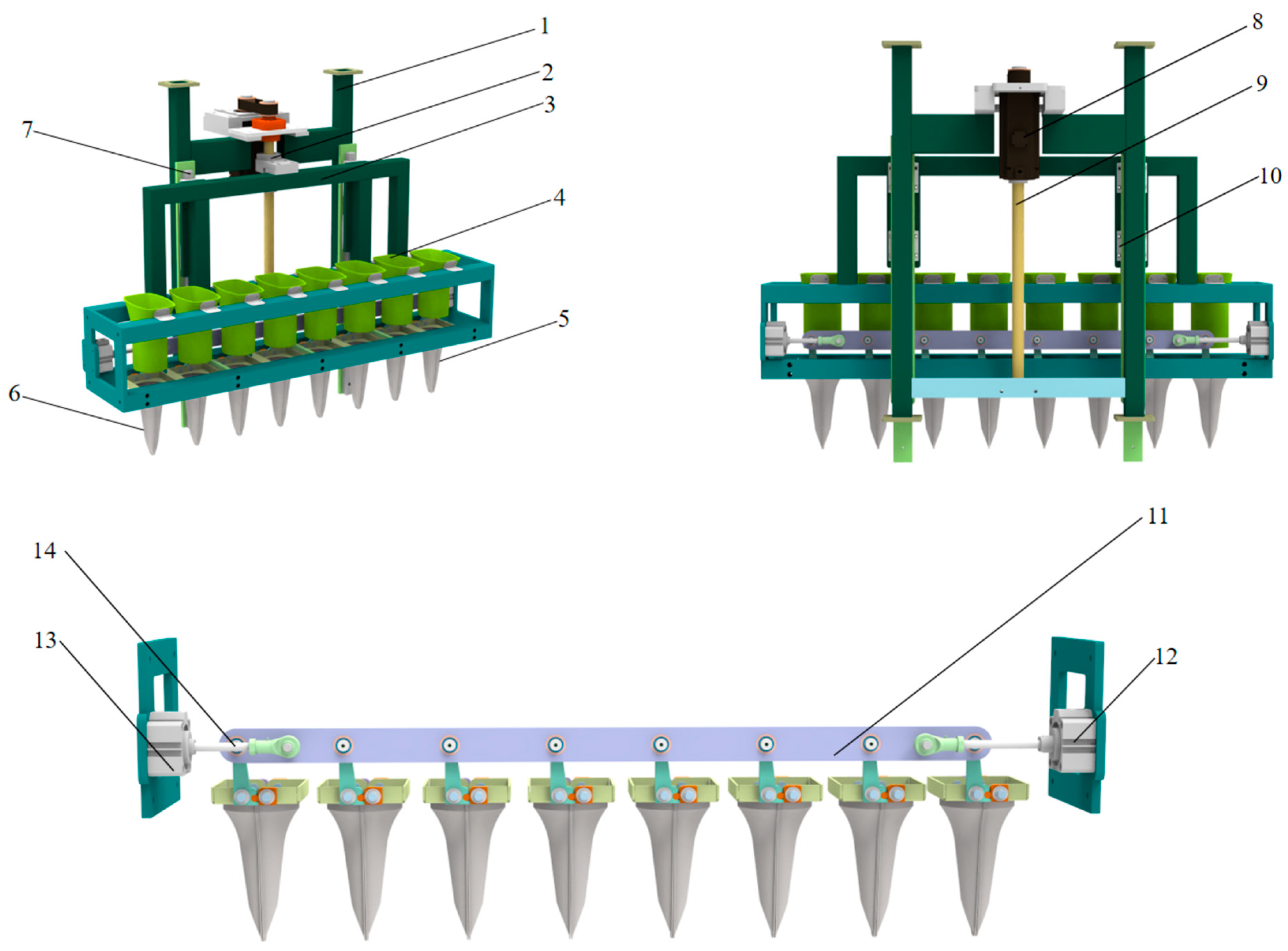
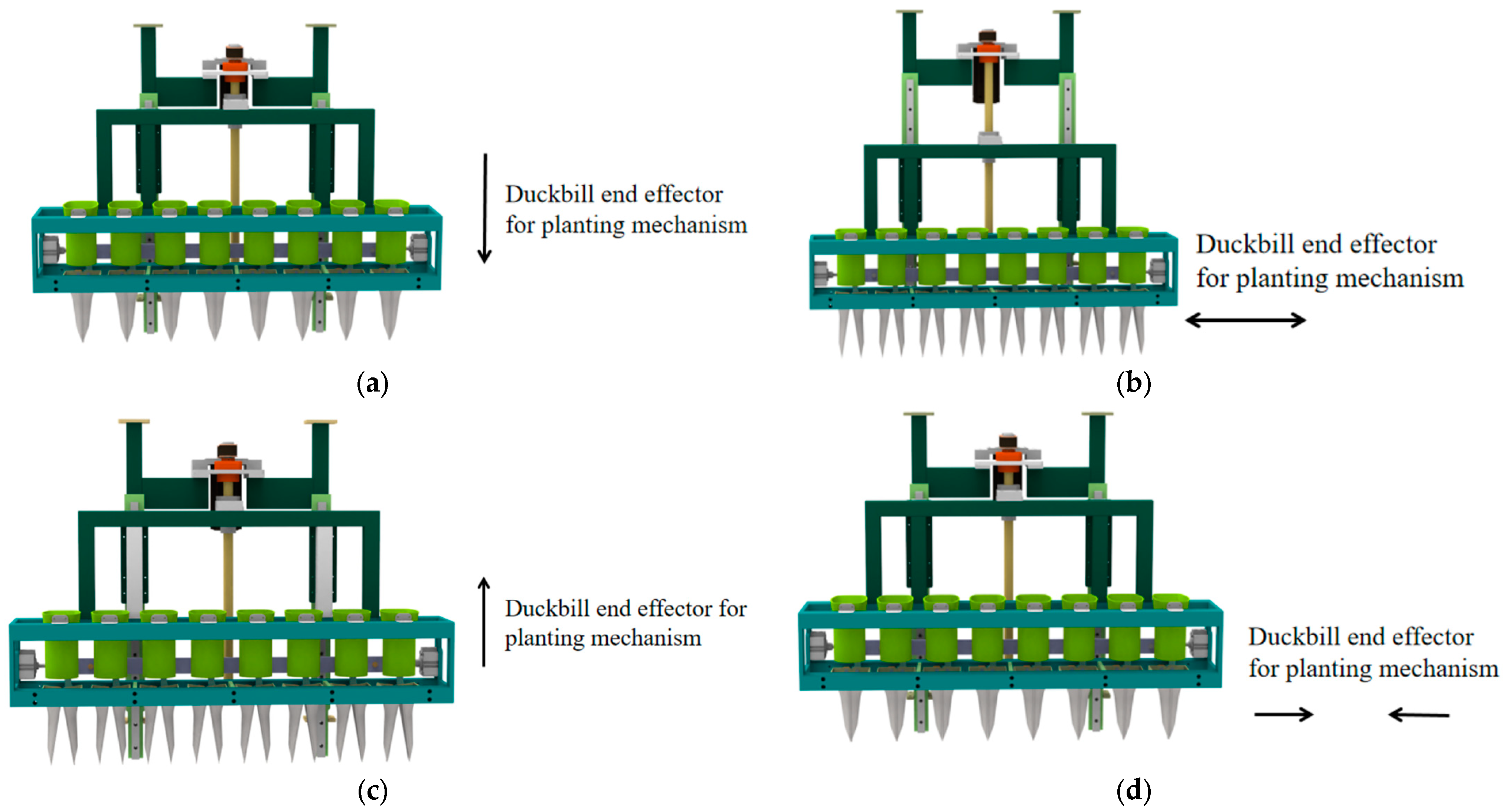
2.2. Structure and Working Principle of Planting Mechanism

The planting mechanism mainly includes a driving motor, a driving rod, a planting frame, a linkage rod, opening and closing cylinders, duckbill-type end effectors, and other components, as shown in Figure 2, and its working principle is shown in Figure 3. The driving motor drives the screw to rotate and the screw rotation drives the screw nut to move up and down. The screw nut is connected to the driving rod, so that the duckbill-type planting end effector moves vertically up and down through the guide rail slider mechanism. The duckbill planting end effector is initially located at the initial position above the planting mechanism, as shown in Figure 3a. When the duckbill planting end effector moves vertically downward to the planting position, the opening and closing cylinder works. Opening and closing cylinder 1 pushes out the opening and closing rod, opening and closing cylinder 2 contracts the opening and closing rod, and the connecting linkage rod performs a short lateral displacement. The right half of the 8 duckbill planting end effectors connected to the linkage rod works, and the left half of the duckbill planting end effectors rotates at a relative angle through engagement with the right half of the duckbill planting end effectors, thereby opening the duckbill planting end effector, as shown in Figure 3b. The seedling pot falls into the hole formed by the opening of the duckbill planting end effector, and then the driving motor rotates in the opposite direction and the planting mechanism rises vertically to the initial position, as shown in Figure 3c. Then, opening and closing cylinder 1 contracts the opening and closing rod, opening and closing cylinder 2 pushes out the opening and closing rod, and the duckbill planting end effector closes, as shown in Figure 3d.

3. Design of Key Components

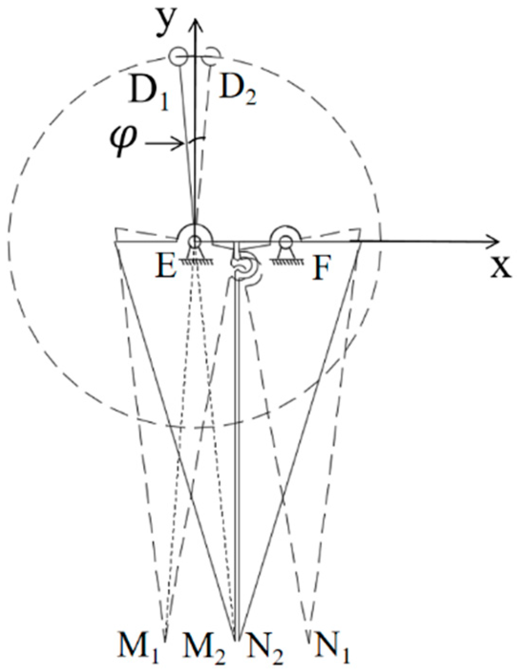
3.1. Establishment of Kinematic Model of Planting Mechanism

The planting mechanism included a power transmission mechanism and a planting end effector. The design of the power transmission mechanism was the premise for the normal operation of the planting mechanism. In order to meet the requirements of densely planted vegetables with multiple rows, small plant spacing, and small row spacing, a scheme for a motor-driven planting mechanism with a double cylinder driving the planting mechanism was proposed. For the convenience of analysis, each part and the corresponding joint point were simplified in the plane. Among them, the screw driving the driving rod to drive the linkage rod to move up and down was simplified to the screw driving the linkage rod directly to move up and down, and the cylinder was simplified to a single-cylinder drive. The cylinder was used as a driving part to control the telescopic movement of the opening and closing pull rod to drive the linkage rod to move left and right. The top of the linkage rod was connected to the roller bearing in an articulated manner, and the roller bearing produced a relative rolling displacement, thereby driving the duckbill planting end effector to open and close. The simplified diagram of the planting mechanism is shown in Figure 4. L is the effective stroke of the opening and closing cylinder, and D, E, and F are hinge points.

3.2. Design of Power Transmission Mechanism

3.2.1. Design of Motor and Screw

The duckbill planting end effector first accelerates, then moves at a constant speed, and then decelerates. The total weight m of the linkage rod and the 8 duckbill planting end effectors was 10.4 kg. According to the literature [28], the vertical planting resistance of duckbill planting end effectors is between 55–65 N. This paper takes the planting resistance of a single duckbill as 60 N, regards the multi-row planting mechanism as a rigid body, and ignores the deformation factor. Therefore, the planting resistance Ff of the 8 duckbill planting end effectors of the multi-row planting mechanism was 480 N. The force analysis of the screw rod was carried out, and the self-weight of the screw rod was ignored. It can be regarded as a two-force rod, as shown in Figure 5a. The force analysis of the duckbill planting end effector was carried out as shown in Figure 5b.
After force analysis, according to the principle of force balance, the force Fm exerted by the drive motor on the screw was solved as shown in Formulas (1)–(3); the lead Ph of the screw was solved by Formula (4); the maximum stroke of the duckbill planting end effector’s up and down movement was solved by Formula (5); the maximum torque and power required by the drive motor were solved according to Formulas (6) and (7), and the drive motor was selected.
F d + G F f = m a
G = m g
F d = F d = F m
where G is the weight of the linkage rod and the 8 duckbill planting end actuators, N; m is the mass of the linkage rod and the 8 duckbill planting end actuators, kg, take m = 10.4 kg; a is the acceleration of the duckbill planting end actuator during movement, m/s2, take a = 0.5 g m/s2; Ff is the planting resistance of the 8 duckbill planting end actuators, take Ff = 480 N; Fd′ is the force of the screw on the duckbill planting end actuator, N; Fd is the force of the duckbill planting end actuator on the screw, N; and Fm is the force of the drive motor on the screw, N. From Formulas (1)–(3), it can be seen that Fm is 383.28 N.
n · P h = v · 60
where n is the motor speed, rpm, take n = 3000 rmp; and V is the speed of the duckbill planting end effector during movement, m/s, take v = 0.5 m/s. The screw lead Ph is 10 mm. From the table, the screw diameter d is 15 mm.
d · 60 > h
where d is the screw diameter, mm; and h is the movement stroke of the duckbill planting end effector, mm, take h = 400 mm. Substituting the data into Formula (5), we get 15 × 6 > 400, and the designed screw parameters are a lead Ph of 10 mm and screw diameter d of 15 mm, which meets the requirements.
T m a x · 2 π = F m · P h
where Tmax is the maximum driving torque required for motor, N·m. The calculation shows that the maximum driving torque Tmax required for the motor is 0.61 N·m.
P m a x = T m a x · n 2 a
where Pmax is the maximum power required by the motor, kW.
The calculation shows that the maximum power required for the motor is 0.20 kW. Considering the complex soil working environment, the drive motor should have a larger safety factor, so the Mitsubishi HG-KR43J motor was selected, with a rated power of 0.4 kW and a rated torque of 1.3 N·m, which meets the design requirements.

3.2.2. Design of Mechanical-Pneumatic Coupling Duckbill Opening and Closing Mechanism

The opening and closing mode of a single duckbill planting end effector is as follows: point D moves in a circle around point E under the drive of the linkage rod, and the right half duckbill planting end effector opens and closes. The right half duckbill planting end effector and the left half duckbill planting end effector mesh with each other to drive the left half duckbill planting end effector to move. The opening and closing angle of the duckbill planting end effector can be controlled via the telescopic distance of the cylinder rod. By analyzing the kinematic characteristics of the opening and closing control motion joint of the duckbill planting end effector, it can be known that improving the transmission efficiency of the joint and maintaining the stability of the duckbill planting end effector when the displacement constraint condition is the largest can effectively solve the problem of seedling leakage and unstable planting hole diameter during planting, and improve the control ability of the mouth angle and hole diameter. Simplifying the plane, as shown in Figure 6, which is the principle diagram of the duckbill planting end effector, shows that the opening and closing angle of the duckbill planting end effector is controlled by the effective displacement of the D joint [29,30].
When the planting mechanism is performing planting operations, the effective stroke distance of the cylinder was set to L. Since the horizontal displacement distance of the D joint is consistent with L, the relationship between the two is shown in Formula (8); since the angle φ is relatively small in actual motion, the distances of D1E, D2E, EM1, EM2, FN1, and FN2 are approximately regarded as their projections on the XY plane, and the relationship between them is shown in Formula (9). In the triangle OM1N1, ∠M1ON1 = θ, the half-angle formula can be used to determine the relationship between the side length and θ, as shown in Formula (10). After simplification, the relationship between θ and the side length is shown in Formula (11).
L = D 2 D 1
D 1 D 2 M 1 M 2 = D 1 E E M 2 L M 1 M 2 = D 1 E E M 2 M 1 M 2 = L × E M 2 D 1 E M 1 N 1 = 2 M 1 M 2 = 2 L × E M 2 D 1 E
s i n θ 2 = M 1 N 1 2 O M 1 c o s θ = 1 2 s i n θ 2 2
c o s θ = 1 2 L × E M 2 D 1 E × O M 1
Therefore, the opening and closing angle of the duckbill unit is controlled by the movement of the linkage rod. When the duckbill planting end effector was opened by 40°, the relevant parameters of the planting module were substituted into the above formula group, and the movement distance of the linkage rod was 10 mm. Since the linkage rod was connected to the cylinder through the cylinder connector, the stroke of the cylinder only needed to be greater than 10 mm. The cylinder controlled the duckbill end effector to open in the soil. Due to the high recirculation of the soil, the opening and closing action needed to be completed in a shorter time. The larger the inner diameter of the cylinder, the faster the cylinder expansion and contraction speed under the same pressure. The duckbill planting end effector needed to overcome a large reaction force when opening and closing in the soil. As shown in Formula (12), when the working pressure is constant, the larger the inner diameter of the cylinder, the greater the force it generates.
F = 10 P d 2 π 4
where F is the tension at the end of the cylinder, N; P is the working pressure, bar; and d is the diameter of the piston rod in the cylinder, cm.
In summary, the AirTac SDA model 40 × 10 specification cylinder was selected. The inner diameter was 40 mm, the stroke was 10 mm, and it could provide a thrust of 500 N.

3.3. Structural Design of Duckbill Planting End Effector

3.3.1. Strength Analysis of Linkage Rod of Planting Mechanism

Considering the universality of densely planted vegetables, pak choi seedlings with a seedling age of 30–40 days, 4–6 leaves, and a seedling height of 100–130 mm suitable for mechanized transplanting were selected. A single pak choi seedling is shown in Figure 7a. This study selected Shanghai green seedlings cultivated in 128-hole plug trays as the research object. The overall specifications of the plug tray were 540 mm × 280 mm × 40.5 mm, and the size of a single hole was 15 mm × 15 mm at the bottom and 32 mm × 32 mm at the top. The schematic diagram of the seedling pot substrate is shown in Figure 7b.
During the planting operation, the initial posture of the seedling pot in the duckbill planting end effector will affect the posture of the seedling pot falling into the hole, and then determine whether the uprightness of the seedling pot is qualified. Therefore, the seedling pot in the duckbill planting end effector must fit the inner wall of the duckbill planting end effector. According to the shape of the seedling pot matrix, the overall shape of the duckbill planting end effector structure was determined to be conical. As shown in Figure 7a above, the hole tray seedlings cultivated with 128-hole tray seedlings have a space diameter of 50~60 mm and a height of 90~100 mm. Therefore, the diameter of the seedling port of the duckbill unit is determined to be 70 mm. The height of the vegetable seedlings is usually about 90~100 mm, so the height of the duckbill unit was set to 125 mm.
During planting, the duckbill end effector directly interacts with the soil, and the seedling placement area in the upper part of the duckbill end effector is related to the shape of the seedling pot and the volume occupied by the leaves, so there is not much room for optimization design. However, the cone angle part of the duckbill end effector first contacts the soil and is most affected by the resistance of the soil. At the same time, the soil has a certain fluidity. If the cone angle part is optimized to a better level, the planting resistance it encounters can be reduced. Therefore, this study mainly focuses on the cone angle part of the duckbill end effector, as shown in Figure 8.
Based on the external structural design of duckbill implant end effectors in the domestic and foreign literature [31], the following three types are summarized: double incisions, four incisions, and conical types, as shown in Figure 9.

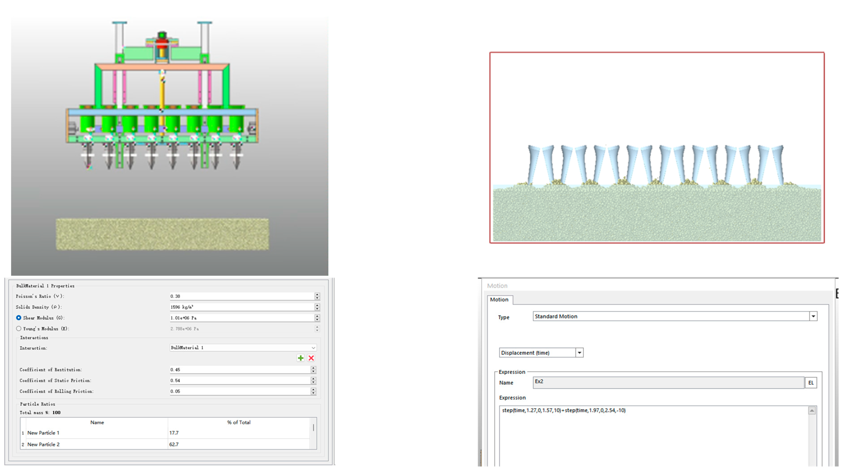
3.3.2. Coupling Simulation Test of Duckbill Planting End Effector

(1)
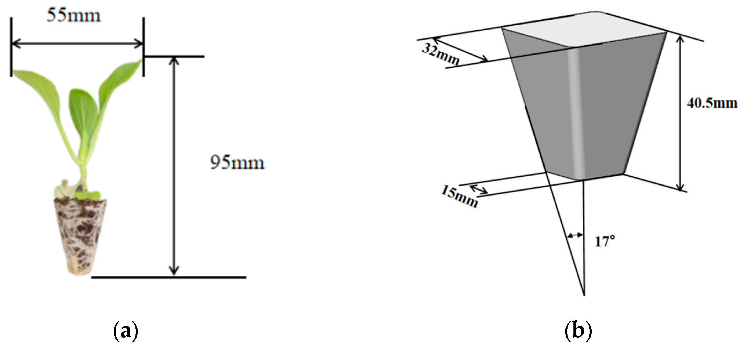
Determination of test parameters
Since the planting mechanism adopts a vertical planting method, the planting speed and planting depth of the duckbill planting end effector were selected as the test parameters of the simulation test. Its movement stroke before contacting the soil was 300 mm, and the duckbill planting depth was set to S0, so the overall movement stroke of the duckbill was (300 + S0) mm. The expected planting frequency of the dense planting transplanter was 6000–8000 plants/h, so the average single planting cycle was about 4 s. A single planting cycle can be divided into four processes: the whole machine moves forward 12 cm, the planting mechanism vertically inserts into the planting soil, the duckbill end effector opens and drops the seedlings, and the planting mechanism vertically leaves the soil. The time allocation for each process was about 1 s. Therefore, in order to achieve the expected design goal, the overall movement and falling time of the duckbill end effector was about 1 s, and the total stroke was (300 + S0) mm. In summary, the planting speed parameters of the duckbill planting end effector were 300 mm/s, 350 mm/s, 400 mm/s, 450 mm/s, and 500 mm/s. Considering the planting requirements of vegetables in dryland transplanting, the planting depth is usually between 60–80 mm. Therefore, the planting depth parameters were 60 mm, 65 mm, 70 mm, 75 mm, and 80 mm. The data Fmax at the maximum resistance during the whole process were selected as the output values of the simulation test.
(2)
Test methods
I. Single-factor test method: For the three external shapes, based on the two factors of planting speed and planting resistance, the influence of single factors on the result indicators was analyzed, and each factor adopted five levels. Three external shapes and two influencing factors were divided into 6 groups of tests; each group of tests was divided 5 times, and a total of 30 coupled simulation tests were conducted. The experimental factor level tables are shown in Table 1 and Table 2. By changing the same parameters under the three external shapes, a comprehensive comparison is made as to which external shape has the smallest planting resistance.
II. Interactive Factor Response Surface Experiment Method: This study uses Design-Expert 13 software to perform interactive factor response surface experimental design. Based on multiple groups of interactive test data, the design compared and analyzed which shape structure has the lowest planting resistance. Based on three shape structure classifications and two influencing factors, three levels were set for each test. Two test parameters were established, namely planting speed and planting depth, and one determination parameter, the shape structure. The indicator response value is the planting resistance. Using the 3-Level Factorial Design method, 39 groups of experiments were conducted.
(3)
Coupling simulation test based on EDEM 2022-RecurDyn 2024 software
This simulation test used the multi-body dynamic simulation software RecurDyn 2024 to simulate the motion state of the planting mechanism driven by the motor. It was coupled with the soil model simulated by EDEM 2022 in the discrete element analysis software to analyze the maximum value Fmax of the dynamic resistance of the duckbill planting end effector under the dynamic reaction force of the soil. The simulation is shown in Figure 10.
(4)
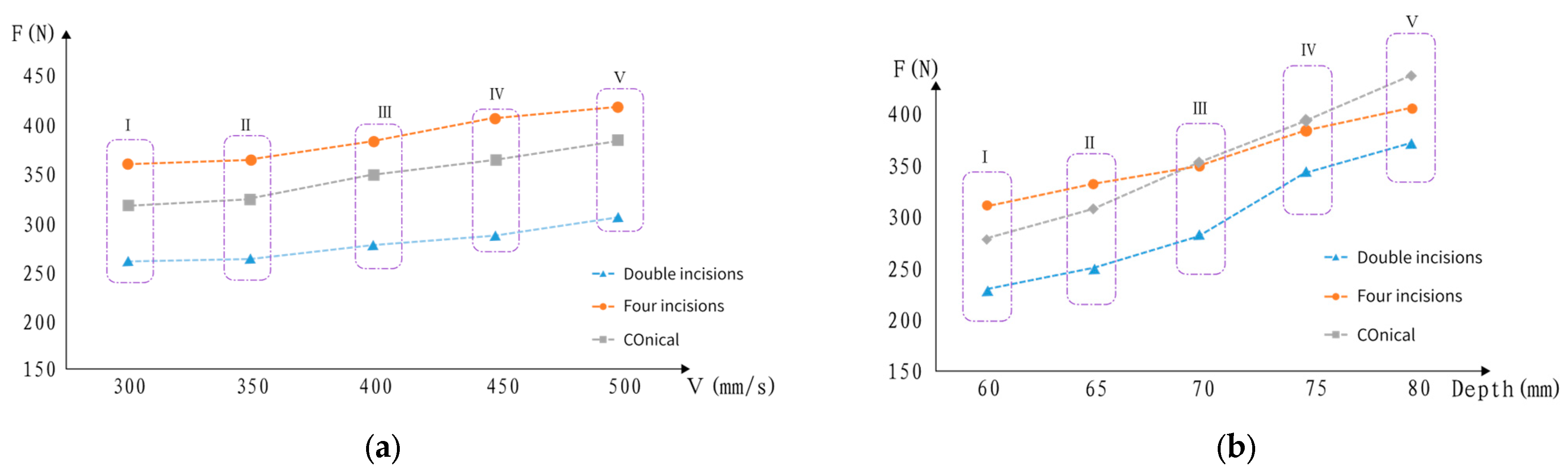
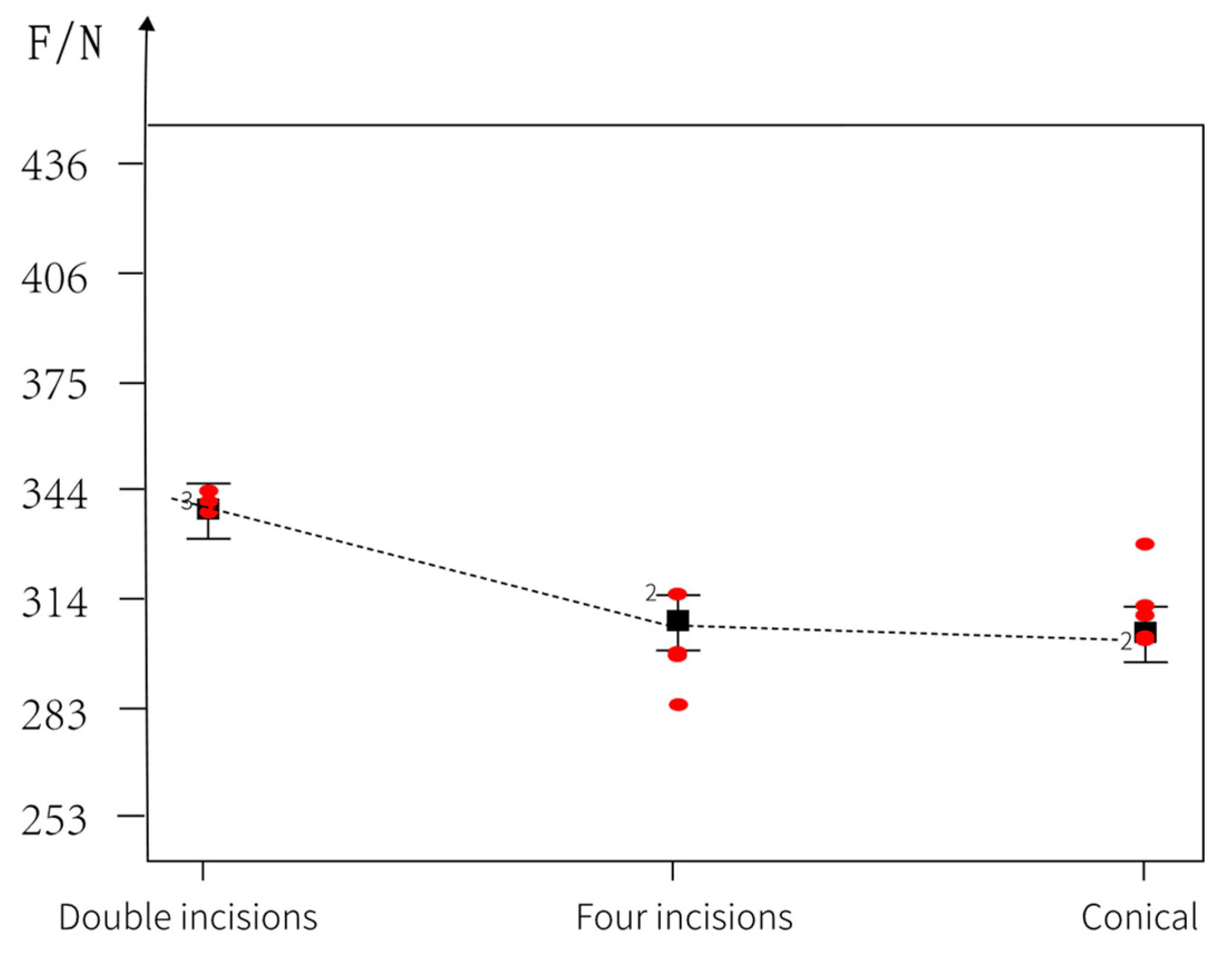
Analysis of single-factor effect
First, the single-factor test method was used to define the planting duckbill as two test factors, planting speed and planting degree, and conduct coupling simulation tests on three duckbill shapes. At the same time, other test factors remained unchanged. The maximum value of the dynamic reaction force of the soil on the planting duckbill was obtained as shown in Table 3 and Table 4; the overall trend of Fmax is shown in Figure 11.
For three different duckbill shapes, at different levels of soil penetration speed, the changes in soil penetration resistance of eight duckbills at the same time are shown in Figure 11. The soil penetration resistance increases slightly with the increase in soil penetration speed. The reason for that is that deep soil has consistent soil fluidity. When the speed of the duckbill entering the soil is greater, the time it stays in the soil is shorter. The shorter the soil flow time, the greater the interference effect of the duckbill on the soil. Therefore, the reaction of the soil on the duckbill is more powerful. For the three types of duckbill shapes, under the same experimental factors, five comparative experiments on soil penetration resistance were conducted. The results showed that in the range of 300–500 mm/s, the double-cut duckbill had smaller soil penetration resistance. However, in order to verify whether the soil penetration speed factor significantly affects the soil penetration resistance and whether the conclusion that the double-notch soil penetration resistance is smaller is correct, a double-interaction-factor response surface test must be conducted for verification.
For three different duckbill shapes and at different levels of soil penetration depth, the simultaneous soil penetration resistance of eight duckbill-type planting end effectors is shown in Figure 11b. The soil penetration resistance increases with the soil penetration depth, and the trend is a slight increase. The reason for that is that when the soil penetration depth is greater, the contact area between the duckbill surface and the soil is larger, and the friction force formed is greater, which hinders the duckbill penetration into the soil. For the three duckbill shapes, under the same experimental factors, five comparative experiments on soil penetration resistance were conducted. The results showed that in the range of 60–80 mm, the double-cut duckbill-type planting end effector had smaller soil penetration resistance. In order to verify whether the soil penetration depth test factors significantly affect the soil penetration resistance and whether the conclusion that the double-notch soil penetration resistance is smaller is correct, a double-interaction-factor response surface test must be conducted for verification.
(5)
Interactive Factor Response Surface Analysis
After setting up the Design-Expert software, 39 groups of tests were required. RecurDyn-EDEM coupling tests were performed based on the test parameters, and the statistics are shown in Table 5.
The Design-Expert software was used to perform multiple regression fitting on the above data to observe the effectiveness of the penetration depth and penetration speed parameters. It can be seen in Table 6 that the p value of the multiple regression fitting variance in the duckbill soil penetration resistance is less than 0.0001, which proves that the effect of the model is significant. The p values of duckbill soil penetration depth, duckbill planting velocity, and duckbill shape are all less than 0.0001, which proves that two experimental factors and one clear factor can have a greater impact on soil penetration resistance. It can be verified that the two factors have a significant effect in the single-factor test.
From the response surface diagrams of the planting resistance value changes in duckbill planting end effectors with different shapes under the action of interactive factors in Figure 12a–c, it can be seen that the planting resistance of the duckbill planting end effector with a double-cut shape is significantly smaller than that of the duckbill planting end effector with a four-cut and conical shape. As shown in Figure 13, a comparative analysis shows that the overall distribution point of the duckbill planting end effector with a double-cut shape is smaller than that of the duckbill planting end effector with a four-cut and conical shape. Through single-factor experiments and two-factor interactive response surface experiments, it can be seen that the planting resistance of the duckbill planting end effector with a double-cut shape is the smallest, so the duckbill planting end effector with a double-cut shape is used.

4. Resistance Verification Test of Duckbill Planting End Effector

4.1. Test Design

The test device consisted of a soil trough, a YZC131 weighing sensor module, an HX711 module, and an STM32 microcontroller. The weighing sensor module was installed at the bottom of the soil trough. The sensor formed a full-bridge circuit through multiple strain gauges. The change in mass in the soil trough caused the strain gauge to deform, resulting in a change in its resistance value to form an analog signal. The HX711 module converted the analog signal into a digital signal and sent it to the STM32 microcontroller. Through the serial port debugging assistant, the value of the soil resistance could be sent to a computer. Through the KEIL 5 programming software in the laptop used, the program was written in C language, and the program was burned into the single-chip computer to detect the soil resistance. For the duckbill planting end effector with a double-cut structure, experiments were carried out based on different planting speeds and different planting depths, and the actual measured values were compared and analyzed to see if they were consistent with the simulation data. In order to simulate a more realistic working environment, the test bench was built on a wheeled frame to complete the soil trough verification test, as shown in Figure 14.

4.2. Analysis of Test Results

The test was repeated three times for different planting speeds and planting depths to obtain the maximum value of the planting resistance in the dynamic process, as shown in Table 7 and Table 8.
Table 7 and Table 8 are plotted and compared with the simulation data, as shown in Figure 15 and Figure 16. By comparison, it is found that the data obtained from the actual test and the data obtained from the simulation test have the same basic trend. The maximum resistance difference at a planting speed of 500 mm/s is 21.2 N, which is 6.98% different from the simulation value, and the other error values are all below 5%. When the planting depth is 75 mm, the actual planting resistance value differs from the simulation value by 29.4 N, which is 8.67% different from the simulation value, and the other errors are all below 5%. The reason for the error is that during the soil transportation process, due to problems such as transportation, the physical properties of the soil after rotary tillage change, resulting in errors between the actual planting resistance and the simulation value. However, the planting resistance trends in the simulation test and the bench test are the same, and the data are basically within the allowable error range, thus proving that the duckbill planting model is correct.

5. Planting Performance Test

5.1. Test Conditions

The test site was the Jiangxinzhou Agricultural Demonstration Base in Zhenjiang City. Before transplanting, a rotary tillage and ridging machine was used to loosen and ridge the soil. The ridge width was set to 1100 mm and the ridge height was 120 mm. The test machine is shown in Figure 17. This test used 128-hole pak choi seedlings cultivated in a greenhouse as the test object. The seedling age was about 40 days, the substrate compaction degree was 1.0, and the pot body moisture content ranged from 55% to 60%, as shown in Figure 18.

5.2. Test Design and Evaluation Index

(1)
Test Design
The parameters, such as the plant spacing of the densely planted vegetable automatic transplanter, were set. The row spacing of the multi-row densely planted transplanter was 120 mm, and the plant spacing was adjusted between 100 and 250 mm. The smaller the plant spacing, the higher the control difficulty and action execution accuracy of the transplanter. Therefore, a plant spacing of 100 mm was selected for the test. In order to verify that the densely planted transplanter could achieve stable and efficient results for vegetables with different planting depth requirements, three common planting depths of 60 mm, 70 mm, and 80 mm were selected. The machine operated at a forward speed of 1.4 km/h. After completing the continuous planting operation, the results were statistically analyzed according to the planting indices.
(2)
Evaluation Index
This study is about an automatic transplanter for densely planted vegetables. The goal is to achieve efficient planting with small plant spacing and small row spacing. Therefore, the planting success rate, plant spacing variation coefficient, and planting efficiency were selected as evaluation indicators.
I. Planting success rate
The planting success rate is the ratio of the number of qualified plantings to the total number of plants tested. The formula is as follows:
R = Z M E O R Z
where Z is the total number of test plants, plant; M is the number of exposed seedlings, plant; E is the number of missed seedlings, plant; O is the number of fallen seedlings, plant; and R is the number of replanted seedlings, plant.
II. Plant spacing variation coefficient
The plant spacing of the automatic transplanter for densely planted vegetables was set according to the specific vegetable variety. However, due to the complexity of field work or the influence of the working state of the transplanter, there may be plant spacing errors during planting, which is called the plant spacing variation coefficient. The calculation formula is as follows:
X = i = 1 n X i n
S x = 1 n 1 i = 1 n X i X ¯ 2
C v = S x X · 100 %
where X ¯ is the average plant spacing, mm; S X is the standard deviation of plant spacing, mm; and C V is the coefficient of variation of plant spacing, %.
III. Planting efficiency
Densely planted vegetables have a high planting density and must be planted efficiently. In order to verify whether the multi-row dense planting transplanter can achieve a planting efficiency of 6000~8000 plants/h, a field test was required. The calculation formula is as follows:
F = Z t × 3600
where F is the planting frequency, plant/hour; Z is the number of seedlings planted in a single test, grain; t is the time of a single test, second.

5.3. Test Results and Analysis

The test planting effect is shown in Figure 19. The test results are shown in Table 9, Table 10 and Table 11.
Aiming to optimize the planting success rate and plant spacing variation coefficient, planting performance tests were conducted at planting depths of 60 mm, 70 mm, and 80 mm. The results showed that when the planting depth was 60 mm, the planting qualification rate was 96.09% and the plant spacing variation coefficient was 3.46%; when the planting depth was 70 mm, the planting qualification rate was 96.81% and the plant spacing variation coefficient was 3.61%; when the planting depth was 80 mm, the planting qualification rate was 96.97% and the plant spacing variation coefficient was 3.59%; the average planting success rate was 96.62% and the average plant spacing variation coefficient was 3.55%, both of which meet the relevant standards. Regarding the planting efficiency, nine field tests were conducted, each of which used five trays of 128-hole seedling pots. The test started from the movement of the planting mechanism and ended when the last row of seedling pots was planted. On average, 640 seedlings were planted in each test, and the time taken was 322.9 s. The planting efficiency was 7135 plants/h, which meets the dense planting and transplanting design standard of 6000–8000 plants per hour.
During the test, it was found that some seedlings had fewer roots, and the matrix did not form a soil pot shape, resulting in poor rooting of the seedlings. Some seedlings could not be completely removed by the seedling removal mechanism, and part of the matrix had been scattered before the seedlings fell into the duckbill planting end effector, resulting in missing seedlings or lodging of the seedlings during planting, leading to planting failure. Because the height and expansion of the seedlings were not exactly the same, the duckbill planting end effector often took the seedlings out when closing, resulting in planting failure at the same duckbill planting end effector closing height. After the duckbill planting end effector was opened, the seedling pot fell into the pit. Due to the poor soil covering effect of the soil covering and suppression device, the seedlings tilted or even fell, resulting in planting failure. The above problems will be solved and avoided in subsequent research.
Our proposed solution is to strictly and accurately control the moisture content, substrate ratio, compaction degree, and other factors of the seedlings in the initial seedling raising stage to ensure that the seedling substrate is formed and has good packing properties, thereby improving the qualified planting rate. By modifying the closing height of the duckbill planting end effector, extending the opening time of the duckbill planting end effector, and reducing the phenomenon of the seedlings being taken out when the duckbill planting end effector is closed, the qualified planting rate can be improved. We should also aim to optimize and improve the soil covering and suppression device to improve the reflowability of the soil after planting, reduce the phenomenon of seedlings lodging in the pot, and improve the qualified planting rate.

6. Conclusions

(1)
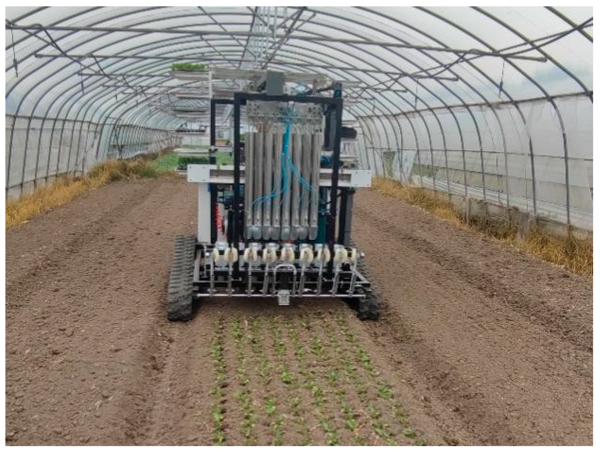
Based on the agronomic requirements of densely planted vegetables with multiple rows, small plant spacing, and small row spacing, an eight-row planting mechanism driven by a motor and a cylinder coupling was designed to overcome the problem of large plant spacing and row spacing in existing mechanized planting structures. The feasibility of the planting mechanism was verified by establishing a kinematic model.
(2)
The RecurDyn 2024-EDEM 2022 coupling simulation method was used to compare and analyze the planting resistance of three duckbill planting end effectors with different external structures based on the two experimental factors of planting speed and planting depth. The external structure with the smallest planting resistance was selected. Design-Expert software was used to analyze the results. Single-factor analysis and two-factor interactive analysis were performed. It was concluded that the duckbill planting end effector with a double-cut structure had the smallest planting resistance.
(3)
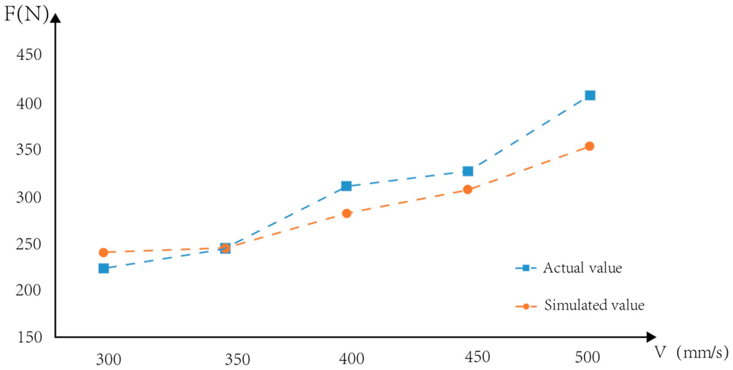
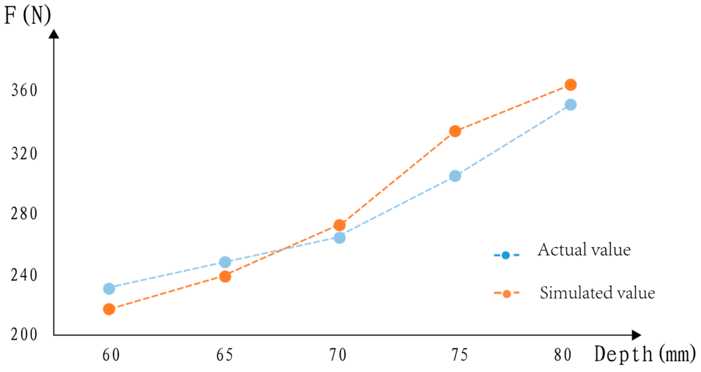
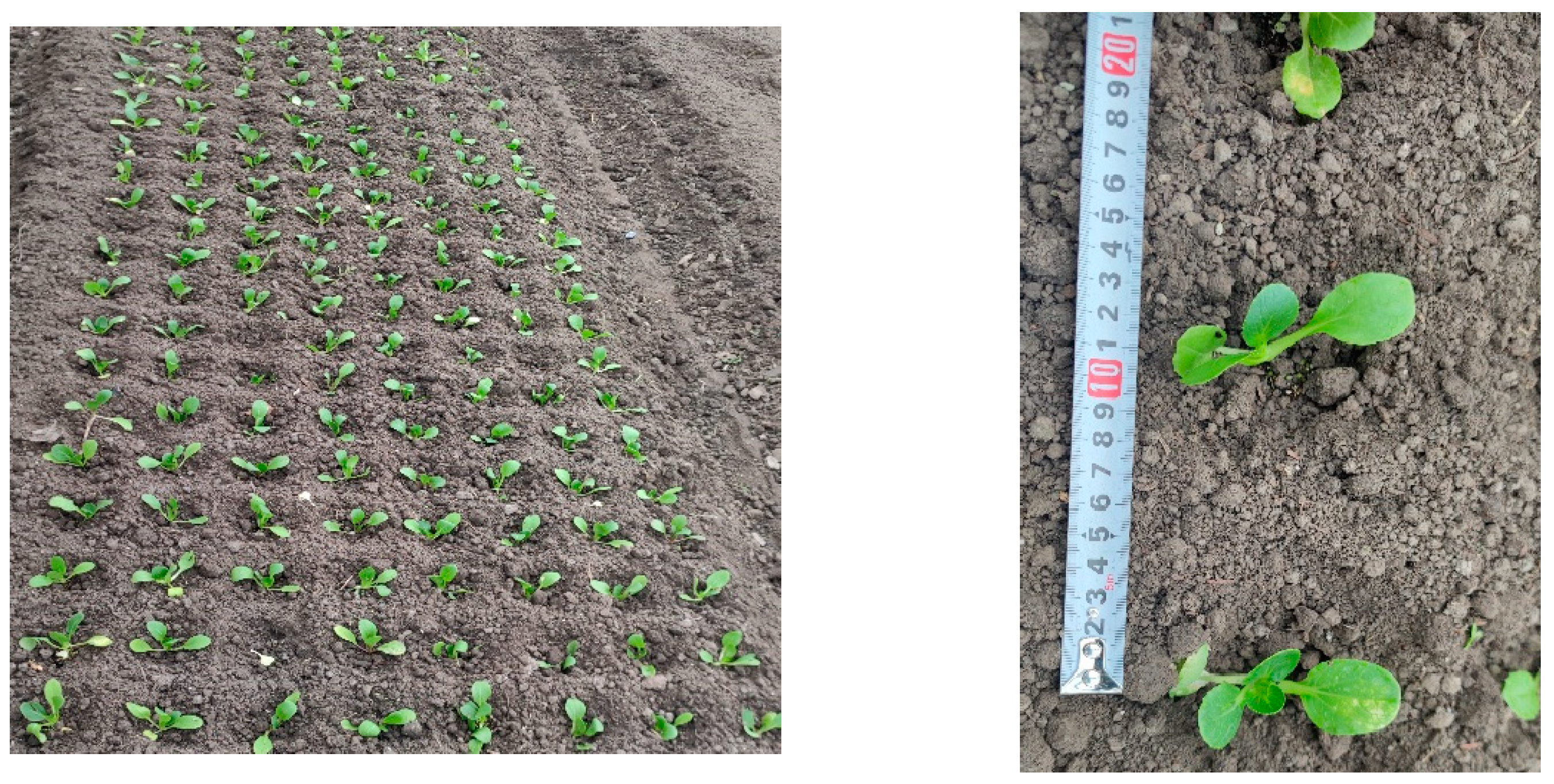
The planting resistance verification system of the duckbill planting end effector was used to analyze the changes in planting resistance at different planting speeds and planting depths. The correctness of the simulation model was verified by comparing the actual planting resistance value with the simulation test value. A performance test of the planting mechanism was used to verify the coordination of the key components and the planting effect. The test results showed that the planting qualification rate of the prototype reached 96.62%, the various components had good coordination, and the planting spacing variation coefficient was only 3.55%. The planting efficiency reached about 7135 plants/h, which meets the agronomic requirements of dense vegetable transplanting.
(4)
Next, the kinematic model needs to be further refined and optimized, considering more variables in practical applications such as soil moisture, terrain changes, etc., to improve the adaptability and stability of the planting mechanism; developing an intelligent control system to automatically adjust the planting parameters will improve work efficiency and adaptability. This study solves the problem that existing planting mechanisms cannot meet the agronomic requirements of densely planted vegetables, reduces labor costs, improves production efficiency, and promotes the development of agricultural mechanization in the direction of efficiency, precision, and intelligence.

Author Contributions

Conceptualization, J.S. and J.H.; methodology, J.S., J.H. and J.L.; software, J.S. and J.L.; validation, J.S. and J.H.; formal analysis, J.S., J.H. and M.Y.; investigation, J.S. and T.Z.; resources, J.H.; data curation, R.Y. and W.L.; writing—original draft preparation, J.S.; writing—review and editing, J.S., J.H. and J.L. All authors have read and agreed to the published version of the manuscript.

Funding

This work was supported by the Shanghai Green Leafy Vegetable Industry Technology System Construction—Development and Application of Key Technologies for high-density green Leafy Vegetable transplanting [Shanghai Nongke (2023) No. 2], the Jiangsu Province Agricultural Science and Technology Independent Innovation Fund Project (CX (22)2022), and the Jiangsu Province Key Research and Development Plan—Modern Agriculture Project (BE2021342). A Project Funded by the Priority Academic Program Development of Jiangsu Higher Education Institutions (No. PAPD-2023-87).

Institutional Review Board Statement

Not applicable.

Data Availability Statement

Data are contained within the article.

Conflicts of Interest

The authors declare no conflicts of interest.

References

  1. Periasamy, V.; Gounder, D.V.M.; Ramasamy, K. Factors influencing the performance of mechanical end effector during automatic transplanting of tomato seedlings. J. Appl. Nat. Sci. 2022, 14, 227–231. [Google Scholar] [CrossRef]
  2. Wu, G.; Wang, S.; Zhang, A.; Xiao, Y.; Li, L.; Yin, Y.; Li, H.; Wen, C.; Yan, B. Optimized design and experiment of a self-covering furrow opener for an automatic sweet potato seedling transplanting machine. Sustainability 2023, 15, 13091. [Google Scholar] [CrossRef]
  3. Sharma, A.; Khar, S. Design and development of a vegetable plug seedling transplanting mechanism for a semi-automatic transplanter. Sci. Hortic. 2024, 326, 112773. [Google Scholar] [CrossRef]
  4. Ji, D.; Liu, L.; Zeng, F.; Zhang, G.; Liu, Y.; Diao, H.; Tian, S.; Zhao, Z. Design and Experimental Study of a Traction Double-Row Automatic Transplanter for Solanum lycopersicum Seedlings. Horticulturae 2024, 10, 692. [Google Scholar] [CrossRef]
  5. Ji, D.; Tian, S.; Wu, H.; Zhao, B.; Gong, Y.; Ma, J.; Zhou, M.; Liu, W. Design and experimental verification of an automatic transplant device for a self-propelled flower transplanter. J. Braz. Soc. Mech. Sci. Eng. 2023, 45, 420. [Google Scholar] [CrossRef]
  6. Markumningsih, S.; Hwang, S.-J.; Kim, J.-H.; Jang, M.-K.; Nam, J.-S. Stress Simulation on Cam-Type Transplanting Device of Semiautomatic Vegetable Transplanter. Agriculture 2023, 13, 2230. [Google Scholar] [CrossRef]
  7. Miah, M.S.; Rahman, M.M.; Hoque, M.A.; Ibrahim, S.M.; Sultan, M.; Shamshiri, R.R.; Ucgul, M.; Hasan, M.; Barna, T.N. Design and evaluation of a power tiller vegetable seedling transplanter with dibbler and furrow type. Heliyon 2023, 9, e17827. [Google Scholar] [CrossRef] [PubMed]
  8. Liu, W.; Tian, S.; Wang, Q.; Jiang, H. Key technologies of plug tray seedling transplanters in protected agriculture: A review. Agriculture 2023, 13, 1488. [Google Scholar] [CrossRef]
  9. Paudel, B.; Basak, J.K.; Jeon, S.W.; Lee, G.H.; Deb, N.C.; Karki, S.; Kim, H.T. Working speed optimisation of the fully automated vegetable seedling transplanter. J. Agric. Eng. 2024, 55, 1569. [Google Scholar] [CrossRef]
  10. Sharma, A.; Khar, S.; Chaudhary, D.; Thakur, P. Study of biometric attributes of plug type tomato seedlings pertinent to transplanter design. Indian J. Ecol. 2023, 50, 503–507. [Google Scholar]
  11. Habineza, E.; Ali, M.; Reza, M.N.; Woo, J.-K.; Chung, S.-O.; Hou, Y. Vegetable transplanters and kinematic analysis of major mechanisms: A review. Korean J. Agric. Sci. 2023, 50, 113–129. [Google Scholar] [CrossRef]
  12. Elwakeel, A.E.; Mazrou, Y.S.; Eissa, A.S.; Okasha, A.M.; Elmetwalli, A.H.; Makhlouf, A.H.; Metwally, K.A.; Mahmoud, W.A.; Elsayed, S. Design and Validation of a Variable-Rate Control Metering Mechanism and Smart Monitoring System for a High-Precision Sugarcane Transplanter. Agriculture 2023, 13, 2218. [Google Scholar] [CrossRef]
  13. Li, M.; Xiao, L.; Ma, X.; Yang, F.; Jin, X.; Ji, J. Vision-based a seedling selective planting control system for vegetable transplanter. Agriculture 2022, 12, 2064. [Google Scholar] [CrossRef]
  14. Stubbs, S.; Colton, J. The Design of a Mechanized Onion Transplanter for Bangladesh with Functional Testing. Agriculture 2022, 12, 1790. [Google Scholar] [CrossRef]
  15. Chen, K.; Yuan, Y.; Zhao, B.; Jin, X.; Lin, Y.; Zheng, Y. Finite element modal analysis and experiment of rice transplanter chassis. Int. J. Agric. Biol. Eng. 2022, 15, 91–100. [Google Scholar] [CrossRef]
  16. Paradkar, V.; Raheman, H.; Rahul, K. Development of a metering mechanism with serial robotic arm for handling paper pot seedlings in a vegetable transplanter. Artif. Intell. Agric. 2021, 5, 52–63. [Google Scholar] [CrossRef]
  17. Li, P.; Yun, Z.; Gao, K.; Si, L.; Du, X. Design and Test of a Force Feedback Seedling Pick-Up Gripper for an Automatic Transplanter. Agriculture 2022, 12, 1889. [Google Scholar] [CrossRef]
  18. Yang, Q.; Zhang, R.; Jia, C.; Li, Z.; Zhu, M.; Addy, M. Study of dynamic hole-forming performance of a cup-hanging planter on a high-speed seedling transplanter. Front. Mech. Eng. 2022, 8, 896881. [Google Scholar] [CrossRef]
  19. Zhang, M.; Jiang, Z.; Jiang, L.; Wu, C.; Yang, Y. Design and Test of the Seedling Cavitation and Lodging Monitoring System for the Rape Blanket Seedling Transplanter. Agriculture 2022, 12, 1397. [Google Scholar] [CrossRef]
  20. Khadatkar, A.; Mathur, S. Design and development of an automatic vegetable transplanter using a novel rotating finger device with push-type mechanism for plug seedlings. Int. J. Veg. Sci. 2022, 28, 121–131. [Google Scholar] [CrossRef]
  21. Yang, J.; Zhou, M.; Yin, D.; Yin, J. Design and Development of Rice Pot-Seedling Transplanting Machinery Based on a Non-Circular Gear Mechanism. Appl. Sci. 2024, 14, 1027. [Google Scholar] [CrossRef]
  22. Zhao, X.; Hou, Z.; Zhang, J.; Yu, H.; Hao, J.; Liu, Y. Study on the Hole-Forming Performance and Opening of Mulching Film for a Dibble-Type Transplanting Device. Agriculture 2024, 14, 494. [Google Scholar] [CrossRef]
  23. Haili, Z.; Wei, Y.; Gaohong, Y.; Bin, W.; Bingliang, Y. Optimization Design and Experiments of Ditching Multi-bar Seedling Planting Mechanism. Trans. Chin. Soc. Agric. Mach. 2023, 54, 79–86. [Google Scholar]
  24. Lei, W.; Liang, S.; Yadan, X.; Gaohong, Y.; Gervais, N.L.; Jiahui, H. Multi-pose Motion Synthesis of Three-arm Gear Train Planting Mechanism Based on Genetic Algorithm. Trans. Chin. Soc. Agric. Mach. 2022, 53, 70–77. [Google Scholar]
  25. Gaohong, Y.; Zhenpiao, L.; Lehui, X.; Peng, Z.; Chuanyu, W. Optimization design and test of large spacing planetary gear train for vegetable pot-seedling planting mechanism. Trans. Chin. Soc. Agric. Mach. 2015, 46, 38–44. [Google Scholar]
  26. Gaohong, Y.; Ye, J.; Shushu, C.; Bingliang, Y.; Jinbo, G.; Xiong, Z. Design and test of clipping-plug type transplanting mechanism of rice plug-seedling. Trans. Chin. Soc. Agric. Mach. 2019, 50, 100–108. [Google Scholar]
  27. Hu, S.; Hu, M.; Yan, W.; Zhang, W. Design and experiment of an integrated automatic transplanting mechanism for picking and planting pepper hole tray seedlings. Agriculture 2022, 12, 557. [Google Scholar] [CrossRef]
  28. Shi, L.; Zhao, W.; Sun, W. Parameter calibration of soil particles contact model of farmland soil in northwest arid region based on discrete element method. Trans. Chin. Soc. Agric. Eng. 2017, 33, 181–187. [Google Scholar]
  29. Daqing, Y.; Nuoyi, Z.; Maile, Z.; Yuchao, Y.; Size, Y.; Jinwu, W. Optimal Design and Experiment of High Speed Duckbill Planting Mechanism with Variable Catch-seedling Attitude. Trans. Chin. Soc. Agric. Mach. 2020, 51, 66–72. [Google Scholar]
  30. Ji, J.; Yang, L.; Jin, X.; Gao, S.; Pang, J.; Wang, J. Design and parameter optimization of planetary gear-train slip type pot seedling planting mechanism. Trans. CSAE 2018, 34, 83–92. [Google Scholar]
  31. Long, Z.; Bo, Y.; Xin, J. Structure Design of Duck Mouth Transplanting End Actuator Based on TRIZ Theory. Agric. Eng. 2020, 10, 76–80. [Google Scholar]
Figure 1. Structural diagram of densely planted vegetables automatic transplanter. 1. seedling taking and dropping mechanism; 2. seedling tray conveying mechanism; 3. variable-distance dispersion mechanism; 4. planting mechanism; 5. soil covering mechanism; 6. air compressor; 7. chassis; 8. power generator; 9. seedling tray recovery mechanism; 10. seedling tray storage rack.
Agriculture 14 01357 g001
Figure 2. Structural diagram of planting mechanism. 1. planting frame; 2. screw nut; 3. driving rod; 4. seedling guide bucket; 5. right half of the duckbill planting end effectors; 6. left half of the duckbill planting end effectors; 7. guide rail; 8. driving motor; 9. screw; 10. slider; 11. linkage rod; 12. opening and closing cylinder 1; 13. opening and closing cylinder 2; 14. opening and closing rod.
Agriculture 14 01357 g002
Figure 3. Working principle diagram of planting mechanism: (a) duckbill planting end effector descending stage; (b) duckbill planting end effector opening stage; (c) duckbill planting end effector rising stage; and (d) duckbill planting end effector closing stage.
Agriculture 14 01357 g003
Figure 4. Simplified diagram of planting mechanism.
Agriculture 14 01357 g004
Figure 5. Diagram of force analysis: (a) diagram of screw force analysis; and (b) diagram of duckbill planting end effector force analysis.
Agriculture 14 01357 g005
Figure 6. Simplified diagram of duckbill planting end effector.
Agriculture 14 01357 g006
Figure 7. Schematic diagram of seedlings in pot: (a) diagram of pak choi seedlings in pot; and (b) schematic diagram of matrix in three dimensions.
Agriculture 14 01357 g007
Figure 8. Two-stage duck-billed transplanting end effector.
Agriculture 14 01357 g008
Figure 9. Different types of two-stage duck-billed transplanting end effector shapes: (a) double incisions type; (b) four incisions type; and (c) conical type.
Agriculture 14 01357 g009
Figure 10. Coupling simulation of duckbill planting end effector.
Agriculture 14 01357 g010
Figure 11. Effects of different factors on the planting resistance of duckbill planting end effector: (a) effect of single-factor planting speed on the resistance of duckbill planting end effector; and (b) effect of single-factor planting depth on the resistance of duckbill planting end effector.
Agriculture 14 01357 g011
Figure 12. Response surface diagram of the planting resistance changes in duckbill planting end effectors with different shapes: (a) response surface diagram of planting resistance changes in duckbill planting end effector with double incisions; (b) response surface diagram of planting resistance changes in duckbill planting end effector with four incisions; and (c) response surface diagram of planting resistance changes in duckbill planting end effector with conical shape.
Agriculture 14 01357 g012
Figure 13. Response surface diagram of the planting resistance changes in duckbill planting end effectors with different shapes.
Agriculture 14 01357 g013
Figure 14. Resistance test of duckbill planting end effector.
Agriculture 14 01357 g014
Figure 15. The comparison of planting resistance at different planting speeds.
Agriculture 14 01357 g015
Figure 16. The comparison of planting resistance at different planting depths.
Agriculture 14 01357 g016
Figure 17. Automatic transplanter for densely planted vegetables.
Agriculture 14 01357 g017
Figure 18. 128 holes for pak choi seedlings.
Agriculture 14 01357 g018
Figure 19. Planting mechanism performance test: (a) test effect; and (b) measurement of plant spacing.
Agriculture 14 01357 g019
Table 1. Level table of planting speed test parameters.
ShapePlanting Speed (mm/s)
Double incisions300350400450500
Four incisions300350400450500
Conical350350400450500
Table 2. Level table of planting depth test parameters.
ShapePlanting Depth (mm)
Double incisions300350400450500
Four incisions300350400450500
Conical350350400450500
Table 3. Test data for different transplanting speeds.
Test GroupShapePlanting Speed (mm/s)
1Double incisions300350400450500
Planting resistance (N)259.5261.4275.9285.7303.6
2Four incisions300350400450500
Planting resistance (N)358.1361.8381.2405.2415.7
3Conical300350400450500
Planting resistance (N)315.7321.8348.5360.8381.6
Table 4. Test data for different transplanting depths.
Test GroupShapePlanting Depth (mm)
1Double incisions6065707580
Planting resistance (N)225.3246.8278.9339.3368.4
2Four incisions6065707580
Planting resistance (N)307.9328.6345.7380.5401.5
3Conical6065707580
Planting resistance (N)275.4304.7348.8389.5433.7
Table 5. Effects of speed and depth on different duckbill planting end effectors.
Test GroupDepth (mm)Speed (mm/s)ShapeResistance (N)
160400Double incisions229.5
260500Double incisions268.3
370400Double incisions302.8
460300Conical275.6
560400Four incisions320.5
670400Double incisions303.5
770400Four incisions356.8
870400Double incisions309.5
970400Conical342.5
1070400Four incisions325.6
1180400Double incisions416.5
1270400Conical339.8
1380500Conical469.8
1470300Double incisions290.6
1560500Four incisions344.3
1670300Four incisions319.8
1770400Double incisions312.5
1860300Four incisions308.6
1980500Double incisions453.8
2080400Conical353.6
2180500Four incisions423.3
2260500Conical338.6
2370500Four incisions379.8
2460400Conical298.6
2570300Conical320.4
2680300Four incisions424.1
2770500Double incisions318.6
2880400Four incisions454.1
2970400Conical341.8
3070400Four incisions340.4
3170500Conical382.7
3270400Double incisions330.5
3370400Four incisions356.8
3460300Double incisions205.6
3570400Conical345.6
3670400Four incisions338.7
3770400Conical342.6
3880300Conical421.3
3980300Double incisions376.8
Table 6. Variance analysis of soil penetration resistance of different duckbill planting end effectors.
ParameterSum of SquaresDegrees of FreedomMean SquareFp
Model1.19 × 105176984.7521.93<0.0001significant
A-Depth80,423.22180,423.22252.46<0.0001
B-Velocity10,582.7110,582.733.22<0.0001
C-shape14,145.927072.9522.2<0.0001
AB112.121112.120.350.5593
AC5052.3722526.187.930.0027
BC642.232321.121.010.3819
A22718.6712718.678.530.0082
B2537.021537.021.690.2082
ABC324.262162.130.510.6084
A2C1367.62683.82.150.1418
B2C1807.852903.932.840.0811
Residual6689.8321318.56
Lost fitting term5460.429606.715.920.0029significant
Pure deviation1229.412102.45
Sum1.25 × 10538
Table 7. Test parameters for different planting speeds.
Test GroupPlanting Speed (mm/s)
300350400450500
Resistance (N)1265.9265.8286.7301.6318.9
2272.2263.9283.6286.9320.8
3270.9253.6290.8291.6334.8
Average value259.5261.4275.9285.7303.6
Table 8. Test parameters for different transplanting depths.
Test GroupPlanting Depth (mm)
6065707580
Resistance (N)1238.6253.1272.4308.9356.8
2240.8258.9269.8315.4349.1
3236.1253.4271.8305.6360.2
Average value259.5238.5255.1271.3309.9
Table 9. Planting success rate.
Planting Depth
(mm)
GroupNumber of Plantings
(Plants)
Successful Plantings (Plants)Missed Plantings (Plants)Exposed Seedlings (Plants)Lodging (Plants)Replanting (Plants)Planting Success Rate (%)Average Planting Success Rate (%)
60 mm1640621565397.03%96.09%
2640615693796.09%
36406099510795.15%
70 mm4640628342398.13%96.81%
56406148105395.90%
6640617387596.41%
80 mm7640619673396.72%96.97%
8640627243497.97%
9640610768995.31%
Table 10. Results of plant spacing variation coefficient.
Planting Depth (mm)GroupNumber of Plantings
(Plants)
Average Plant Spacing
(mm)
Standard Deviation of Plant Spacing (mm)Coefficient of Variation of Plant Spacing (%)
60 mm1640101.43.423.46
2640102.44.68
364096.42.35
70 mm4640102.54.213.61
564097.34.11
664096.12.40
80 mm764098.43.533.59
8640102.14.01
9640100.93.27
Table 11. Field time of test.
Group123456789Average
Time (s)321346332314308332310328315322.9
Disclaimer/Publisher’s Note: The statements, opinions and data contained in all publications are solely those of the individual author(s) and contributor(s) and not of MDPI and/or the editor(s). MDPI and/or the editor(s) disclaim responsibility for any injury to people or property resulting from any ideas, methods, instructions or products referred to in the content.

