Article

Simulation and Optimization of a Rotary Cotton Precision Dibbler Using DEM and MBD Coupling

1
College of Mechanical and Electronic Engineering, Tarim University, Alar 843300, China
2
Xinjiang Production and Construction Corps (XPCC) Key Laboratory of Utilization and Equipment of Special Agricultural and Forestry Products in Southern Xinjiang, Alar 843300, China
3
College of Engineering, China Agricultural University, Beijing 100083, China
*
Author to whom correspondence should be addressed.
Agriculture 2024, 14(8), 1411; https://doi.org/10.3390/agriculture14081411
Submission received: 27 July 2024 / Revised: 16 August 2024 / Accepted: 18 August 2024 / Published: 20 August 2024

Abstract

:
Investigating the seeding mechanism of precision seeders is of great significance for improving the quality of cotton sowing operations. This paper designs a rotary type-hole cotton precision mulching dibbler. The main factors influencing the entry of cotton seeds into the seed wheel holes during the seeding process are then theoretically analyzed. Following this, an accurate discrete element model of coated cotton seeds is established and combined with a discrete element method (DEM) and multi-body dynamics (MBD)-coupled simulation model of the seed drill for seed picking and planting. Simulation experiments on the seeding performance of the precision dibbler were performed to study the influence of the seed wheel structure and motion parameters on the picking and planting performance under different speeds. The optimal parameter combination for the seed wheel is obtained through optimization experiments, and a precision dibbler is manufactured for bench testing. The bench test results are consistent with the simulation test results. At the precision dibbler rotation speed of 16 r/min, the qualified index reaches a maximum value of 93.28%, the skip sowing index increases with the precision dibbler rotation speed, and the re-sowing index decreases as the speed increases. These optimization results significantly improved seeding precision and efficiency and are of great significance for the reliability and effectiveness of cotton sowing operations.

1. Introduction

Coupling the discrete element method (DEM) with multi-body dynamics (MBD) to conduct dynamic simulations of complex mechanical structures containing granular materials can effectively improve the dynamic performance of mechanisms and optimize mechanical structures and motion parameters [1,2,3]. This coupling approach can determine the motion behavior of materials and equipment and also predicts the operational performance of equipment [4]. The DEM calculates the loads of bulk granular materials within the geometric bodies of the equipment. The determined values are then input into the MBD to obtain the relative motion of the bodies. Following this, the motion is transferred back to the DEM, which calculates the behavior of the particles and the loads on the geometric bodies based on the motion. This mutual transfer enables coupled calculations [5].
The application of MBD-DEM co-simulation techniques for analyzing the motion state of granular materials in complex structures was first applied in the field of engineering. Lu [6] and Coetzee [4] designed MBD-DEM-coupled simulation models for civil engineering and geotechnical engineering, respectively. Applications have also been presented in aerospace engineering [7] and mining engineering [8]. Ji [9] employed DEM-MBD-coupled simulations to analyze the impact of the landing method and cushioning mechanism on the landing process of the lunar lander. Mohajeri [10] simulated the grabbing process of iron ore under bonding and stress using MBD-DEM-coupled simulations. Shi [11,12] analyzed the influence of compaction operations on the mechanical quality and damage of ballast based on the DEM-MBD-coupled method. Lommen [5] established a framework for the development, validation, and application of combined MBD and DEM simulations. Xiao [13,14] employed one-way-coupled MBD-DEM simulations to determine the influence of damping particles on the dynamic response of gear transmission. Chung [15] and Wu [16] developed bidirectional-coupled MBD-DEM dynamic models for gear and bearing systems, with damping particles filled in the gear cavities, to analyze the system’s dynamic response and conduct experimental validation. The South African company VR Steel optimized the bucket of a dragline through co-simulation using ADAMS-EDEM, increasing the bucket fill rate while reducing the driving forces of the equipment [17].
Recent studies have applied the coupling simulation analysis of DEM and MBD to agricultural engineering [18]. Xu [19] established a simulation analysis model for precision seeders based on DEM-MBD coupling to analyze the soil covering and compaction process during planting operations. There was a strong agreement between the simulation and experimental results, validating the feasibility and applicability of the coupled simulation method. Yan [20] realized simulation analysis of the soybean seeding monomer working process by coupling EDEM and RecurDyn. The simulation results agreed with the test results, proving the accuracy of the coupling method. Liu [21] employed coupled simulation analysis using EDEM and RecurDyn to analyze the load on the rotary tiller shaft of a micro-tiller. Lai [22] conducted a DEM-MBD-coupled simulation experiment to analyze the impact of different seeding chain tension, seeder structure, and operating parameters on the working performance of a chain spoon-type ginseng precision seeder. Kim [23] established a soil-tool coupling simulation model based on DEM-MBD coupling and conducted simulation experiments combined with field measurements. The results indicated the ability of the simulations to effectively and accurately replace on-site testing. Dong [24] used DEM-MBD coupling to simulate the vibration-deep loosening operation, analyzing the soil disturbance and velocity distribution during the operation. However, despite these advances, the application of DEM-MBD coupling specifically to cotton precision dibblers remains relatively limited. In light of this, we believe that exploring the use of DEM-MBD coupling for the design and optimization of cotton precision dibblers could provide new insights into improving seeding performance. The previous literature indicates that the DEM-MBD simulation method can effectively analyze the motion characteristics of seeds in a seeder and determine the main factors affecting the seeding performance of the seeder. Applying DEM-MBD coupling to the design and optimization of cotton precision dibblers differs from previous agricultural applications. This method allows for more accurate prediction of seeding performance by simulating the unique interactions between cotton seeds and the dibbler components, thereby improving the precision and efficiency of cotton sowing operations.
This study aims to improve the structural design of seeding machinery, optimizing the existing configurations to enhance the efficiency of seed picking and sowing processes. Based on the DEM-MBD-coupled simulation model for a cotton precision dibbler, this research analyzed the main factors influencing the seeder’s performance and explored the effects of different rotational speeds and structural and motion parameters of the seed wheel on seeding performance. A consistent trend observed between the simulations and bench tests validates the feasibility of the coupled simulation approach and the effectiveness of the simulation parameters. This work provides a reference for the structural analysis and optimization of the seeding unit.

2. Structure Analysis and Modeling of the Dibbler

Figure 1 presents the rotary type-hole cotton precision dibbler structure designed for the mulching planting mode of cotton in the northwest region of China. The main components of the structure include a seed tube, waist belt, duckbill, seed wheel, disrupter, and a moving plate. The seed tube is designed to guide the cotton seeds falling from the seed box along the correct path into the seed chamber. The outer side of the belt is used to secure the duckbill of the rotary type-hole dibbler, while the inner side is employed to install the type-hole wheel. The cotton seeds fall into the duckbill through the type-hole wheel by gravity. The duckbill, which directly contacts the soil, is a critical component that ensures the cotton seeds are ultimately deposited into the soil. The type-hole wheel is an essential component of the rotary type-hole dibbler, responsible for precisely metering the seeds that enter the seed chamber. The disrupter stirs the seeds within the seed chamber, making them easier for the type-hole wheel to capture. The moving plate connects and secures all components, facilitating rotational seeding.

2.1. Working Principle of the Rotary Type-Hole Dibbler

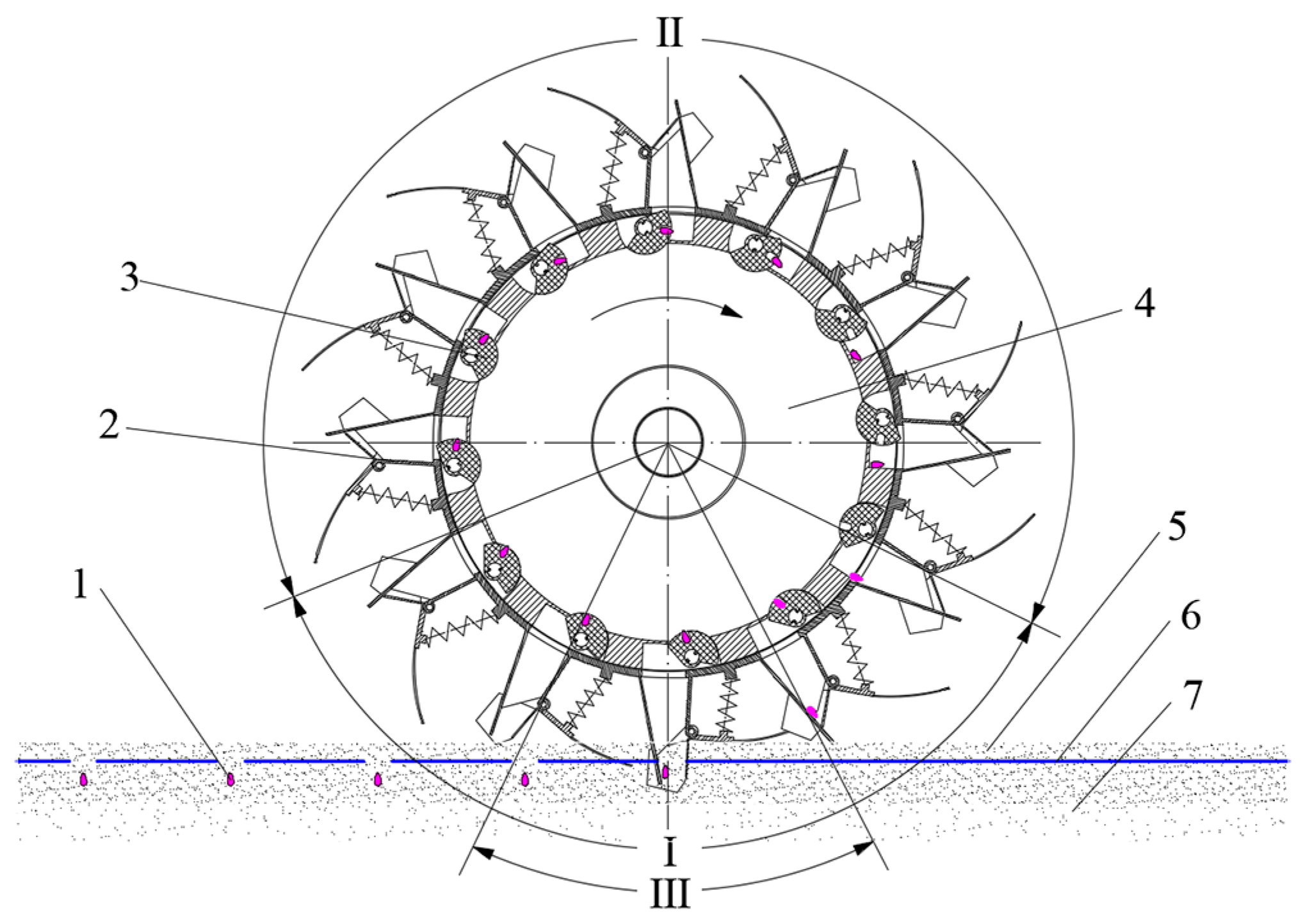
The working process of a dibbler can be divided into three key stages: seed picking and cleaning; seed storage and dropping, and hole forming and seeding (Figure 2). During operation, the dibbler rolls on the mulch and soil at speed v under the drive of the main frame of the seeding machine. The cotton seeds in the seed box then enter the seed chamber through a seed-dropping pipe. The dibbler rotates as the main frame advances. When the type-hole wheel enters the seed picking and cleaning area, the gear plate moves the shifter, which connects with the type-hole wheel, causing the holes on the type-hole wheel to rotate in and out in the seed chamber as the belt rotates, achieving seed picking and cleaning. As the dibbler continues to rotate, the type-hole wheel enters the seed storage and dropping area, and the shifter disengages from the gear plate. The type-hole wheel then returns to its initial position under the action of the torsion spring, and the hole enters the seed storage chamber. As the dibbler continues to rotate, the hole opens downwards, and the cotton seeds slide out under the effect of gravity, passing through the seed storage chamber and entering the duckbill. At this point, the duckbill is in a closed state under the action of the spring. As the dibbler continues to rotate, it enters the seeding area and the duckbill reaches the bottom of the dibbler and inserts into the mulch and soil. The duckbill blade moves upwards under the pressure of the soil, causing the duckbill to open, and the cotton seeds are sown into the soil, thus completing the seeding operation.

2.2. Analysis of the Seed-Picking Movement of the Type-Hole Wheel

The successful seed picking of the dibbler-type hole wheel depends on the movement of the cotton seeds along the surface of the hole wheel. In particular, the cotton seeds can slide, roll, or exhibit a combination of both movements. The dibbler rotates and transfers at a certain speed to the lower layer of the cotton seeds that are in contact with the inner surface of the belt. This speed is less than or equal to the belt speed. The lower cotton seed layer then transfers a certain speed to the upper layer of cotton seeds, thereby transferring its speed to the cotton seeds inside the seed box. The relative speed of the cotton seeds is key in investigating the successful picking of seeds by the type-hole wheel. Without relative movement, successful seed picking cannot occur. Moreover, if the relative speed is too low, the frequency of successful seed picking is low, resulting in low sowing efficiency, while if the relative speed is too high, the type-hole wheel may not pick seeds in time, leading to missed sowing. Therefore, a precision dibbler must have a good seed-picking performance to clearly define the maximum limit speed at which cotton seeds can pass through the type holes of the type-hole wheel.
The motion trajectory equation of the hole wheel during the seed-picking process is described as follows:
S = A sin ( 2 π f t ) f = 360 n z τ
where S is the harmonic motion displacement of the type-hole wheel (mm); A is the vibration amplitude of the type-hole wheel (mm); f is the vibration frequency of the type-hole wheel (Hz); n is the rotational speed of the seeder (r/min); z is the number of teeth on the gear plate; t is the time (min); and τ is the corresponding angular degree of the vibrating motion region of the seed-picking wheel (°).
By taking the first derivative of the motion trajectory equation of the hole wheel with respect to time t, the motion equation for harmonic motion velocity v0 of the hole wheel can be obtained as follows:
v 0 = d S d t = 2 π A cos ( 2 π f )
In addition, the hole wheel moves in a circular motion along with the belt. The motion equation for its circular motion vr′ is given by Equation (3):
v r = ω R = 2 π n R
The velocity of the hole wheel v’ is the vector sum of its harmonic motion velocity v0 and circular motion velocity vr, expressed as Equation (4).
v = v 0 2 + v r 2 = 4 π 2 n 2 R 2 + 4 π 2 A 2 f 2 cos 2 π f t 2
When the cotton seed is in an inverted position and needs to enter the type hole, the maximum distance of movement is required. We assume that the cotton seed approaches the type hole with its germ end, the coordinate origin is at the top right point of the type hole, the X-axis is the tangential direction of the seeding wheel rotation, and the Z-axis is the normal direction of the seeding wheel. When the center of gravity point O′ moves directly above the edge of the type hole, a gap is generated between the lower side of the cotton seed’s center of gravity and the edge of the type hole. Under the influence of gravity, the cotton seed begins to flip counterclockwise until it completely enters the type hole. As the cotton seed enters the type hole, its motion is similar to free falling and rotational motion, and the trajectory of the motion is approximately parabolic, as shown in Figure 3.
When the cotton seed enters the type hole at maximum speed vmax, the motion trajectory of the cotton seed center is given by Equation (5):
D + d l = v max t 0 h = 1 2 g t 0 2
where l is the horizontal distance between the cotton seed center of mass and the type hole wall (mm); t0 is the time taken by the cotton seed center of mass (from the beginning) to fall into the type hole (s); h is the vertical distance that the cotton seed center of mass passes through during the falling process into the type hole (mm); d is the chamfer width (mm); and g is the acceleration due to gravity (m/s2).
From Equation (5), the required time t0 for the cotton seed to fall into the type hole can be obtained as follows:
t 0 = 2 h g
Substituting Equation (6) into Equation (5) gives the terminal velocity vmax at which the cotton seed fills the type hole as Equation (7):
v max = D + d l g 2 h
The relative movement velocity v of the cotton seed with respect to the type-hole wheel is the vector sum of the type-hole wheel movement velocity v′ and the relative velocity of the cotton seed vr with respect to the dibbler, expressed as Equation (8):
v = v 2 + v r 2 = 4 π 2 n 2 R 2 + 4 π 2 A 2 f 2 cos 2 π f t 2 + v r 2
To ensure the seeding accuracy of the furrow opener, the movement velocity v of the cotton seed with respect to the type-hole wheel must be less than the terminal velocity vmax of the cotton seed filling the type hole:
4 π 2 n 2 R 2 + 4 π 2 A 2 f 2 cos 2 π f t 2 + v r 2 < D + d l g 2 h
Equation (9) reveals that when parameters such as the type hole diameter, hole chamfer size, cotton seed dimensions, cotton seed friction coefficient, cotton seed layer height inside the dibbler, and belt radius are constant, the successful filling of cotton seeds into the type-hole wheel is related to its vibration amplitude, the vibration frequency, and the rotation speed of the dibbler.
In the device design process, we used the equations derived in this paper to calculate the key parameters. These equations helped determine the optimal rotation speed of the seeder, the number of gear plate teeth, and the oscillation amplitude of the type-hole wheel to ensure efficient performance in actual operation.

2.3. Establishment of a Discrete Element Model for Coated Cotton Seeds

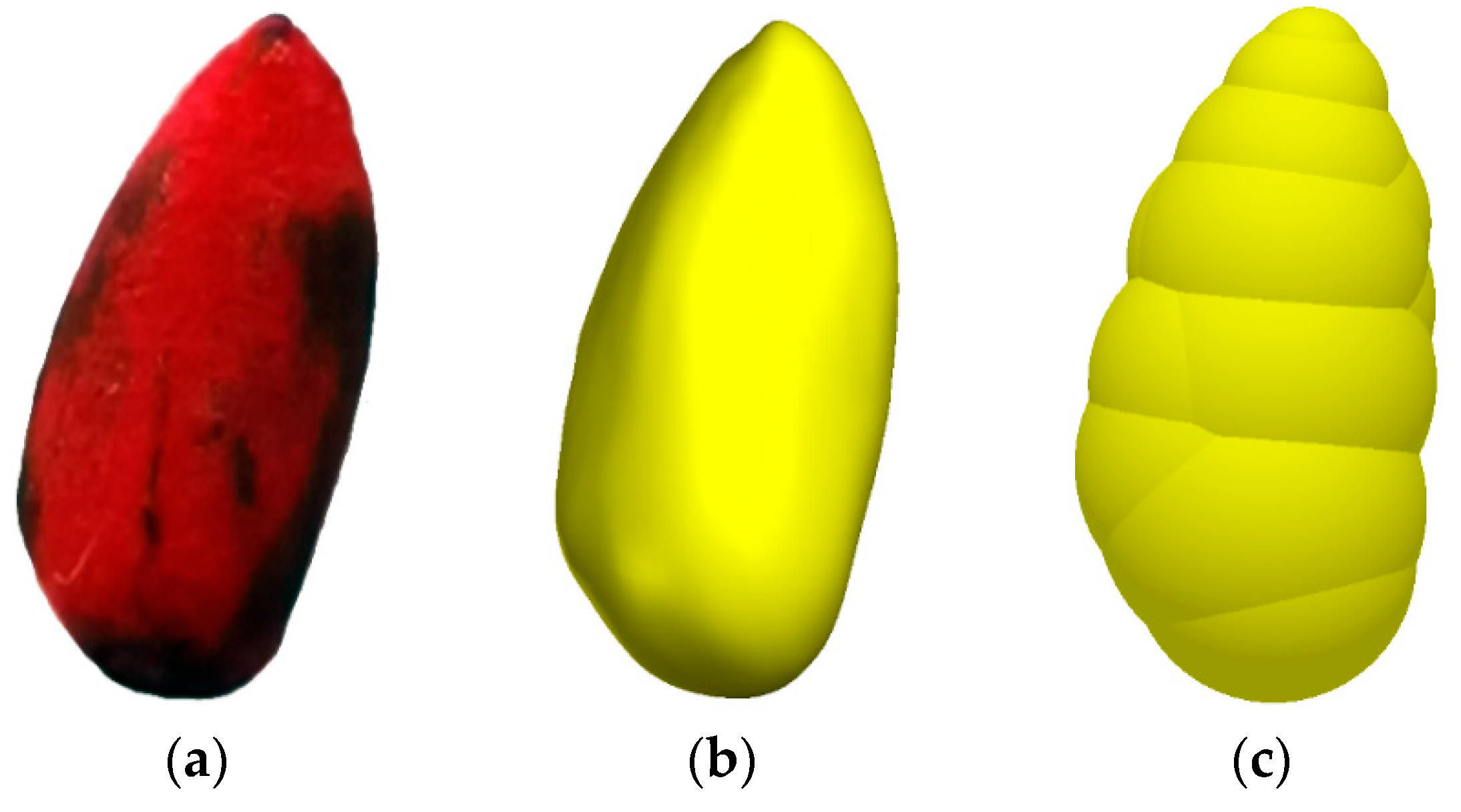
The coated cotton seeds are similar to ovals. This study utilized reverse engineering technology to obtain an accurate contour model of the cotton seeds. A Capture MINI scanner (3D Systems) was employed to perform a three-dimensional (3D) scan of the outer contour of the cotton seed, and Geomagic Wrap 3D 2017 (3D Systems) was used to process the 3D scanning data. Figure 4 presents the process adopted for the cotton seed contour model. The physical coated cotton seed is depicted in Figure 4a. The 3D scanning data were employed to derive the point clouds of the coated cotton seed. The point cloud data were preprocessed to remove noise points from the original point cloud and compress it. It was then encapsulated to form a polygon model. Automatic curvature repair was applied to the missing areas in the polygon model to obtain the contour model of the coated cotton seed, as shown in Figure 4b.
In the discrete element simulation software, spherical or other shaped particles are required to establish the discrete element model of the target materials. However, actual materials are mostly irregular in shape. In the EDEM discrete element software, the bonded particle [25] and multi-sphere [26] methods can be used to establish material models. The bonded particle model requires complex computations and a long simulation time due to the large number of particles used. The multi-sphere aggregation model has lower computational and simulation time requirements. Based on this, we adopt the multi-sphere aggregation model for the simulation experiments. The material contour model is imported into the EDEM software, and according to the model contour, several spherical particles with different diameters are overlapped and stacked to form the model. Figure 4c presents the cotton seed model established by this method, comprising 13 spherical particles with different diameters.

2.4. Establishment of the DEM-MBD Coupling Simulation Model

We implemented the MBD-DEM method using RecurDyn V9R2 (FunctionBay) and EDEM 2020 (DEM-Solutions). RecurDyn can simulate the complex motion of the planter, while EDEM simulates the motion between particles and components. Combining the RecurDyn and EDEM simulations can achieve real-time data transfer, enabling the bidirectional coupling of the cotton seed particles and furrow wheel planter. During the joint simulation, RecurDyn transfers the motion of the belt and seeding wheel components in the planter to EDEM. EDEM then calculates the forces and moments exerted by the cotton seed particles on the moving components of the planter and returns relevant information to RecurDyn. In the next time step, RecurDyn calculates the new displacements, velocities, accelerations, etc. of the components based on the new force, torque information, and planter motion, which are then transferred back to EDEM and implemented on the cotton seed particles. The data exchange process iterates back and forth to achieve bidirectional coupling calculations between RecurDyn and EDEM.
To ensure the reasonable and efficient simulation and calculation of the furrow wheel planter, the planter model is simplified by considering only the components in direct contact with the cotton seeds in the seed chamber, including end caps, fixed plates, belts, seeding wheels, and pushrods. The furrow wheel planter is modeled in 3D using SolidWorks 2018 (Dassault Systemes). The material properties, connections, forces, and contacts are set up in the multibody dynamics software RecurDyn. In the model, the end caps and fixed plates are stationary, the belt rotates clockwise around the axis, the seeding wheel rotates around the axis, and the motion is controlled by torsion springs and limit stops.
The direct target of the furrow wheel planter is the coated cotton seeds. The virtual simulation process uses the Hertz–Mindlin (no slip) model to calculate the interaction relationships between the coated cotton seeds. According to actual operation conditions, cotton seeds are first introduced into the seed chamber from the seed drop tube. Therefore, the mechanism does not move during the seed-filling process. A particle factory is set on the seed drop tube using pre-calibrated discrete element particles of coated cotton seeds with contact parameters. A total of 3000 cotton seed particles are generated at a rate of 1000 seeds/s and in the direction of gravity, with a volume proportional to a normal distribution.
The intrinsic and contact parameters of materials are crucial in the discrete element simulation process. The intrinsic parameters include material density, Poisson’s ratio, elastic modulus, etc., while the contact parameters include the collision coefficient, sliding friction coefficient, and rolling friction coefficient between materials. Table 1 reports the values of the intrinsic and contact parameters of cotton seeds and resin materials, determined based on previous experimental results and references [27,28].
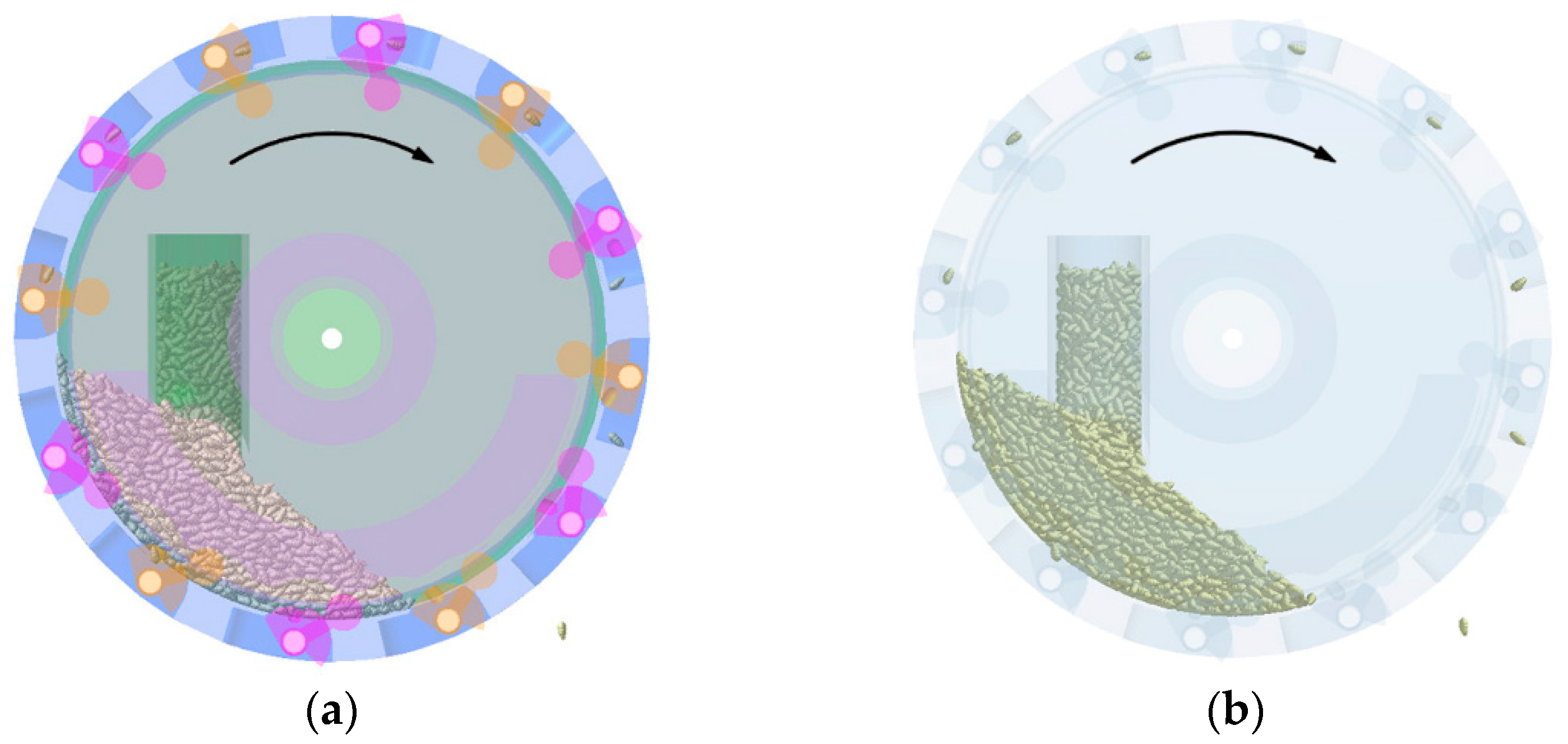
The total simulation time is set as the same value for EDEM and RecurDyn in the coupling interface, and the time step in RecurDyn is fixed as an integer multiple of that in EDEM. Here, the time steps in RecurDyn and EDEM are set as 0.01 s and 2.5 × 10⁻⁶ s, respectively. Once the parameters are set, the coupled simulation commences. After coupling, cotton seed particles also appear in RecurDyn, as shown in Figure 5. The movements of the components of the seeder and the cotton seed particles are simultaneously displayed in the two software, with arrows indicating the rotation direction of the conveyor belt.
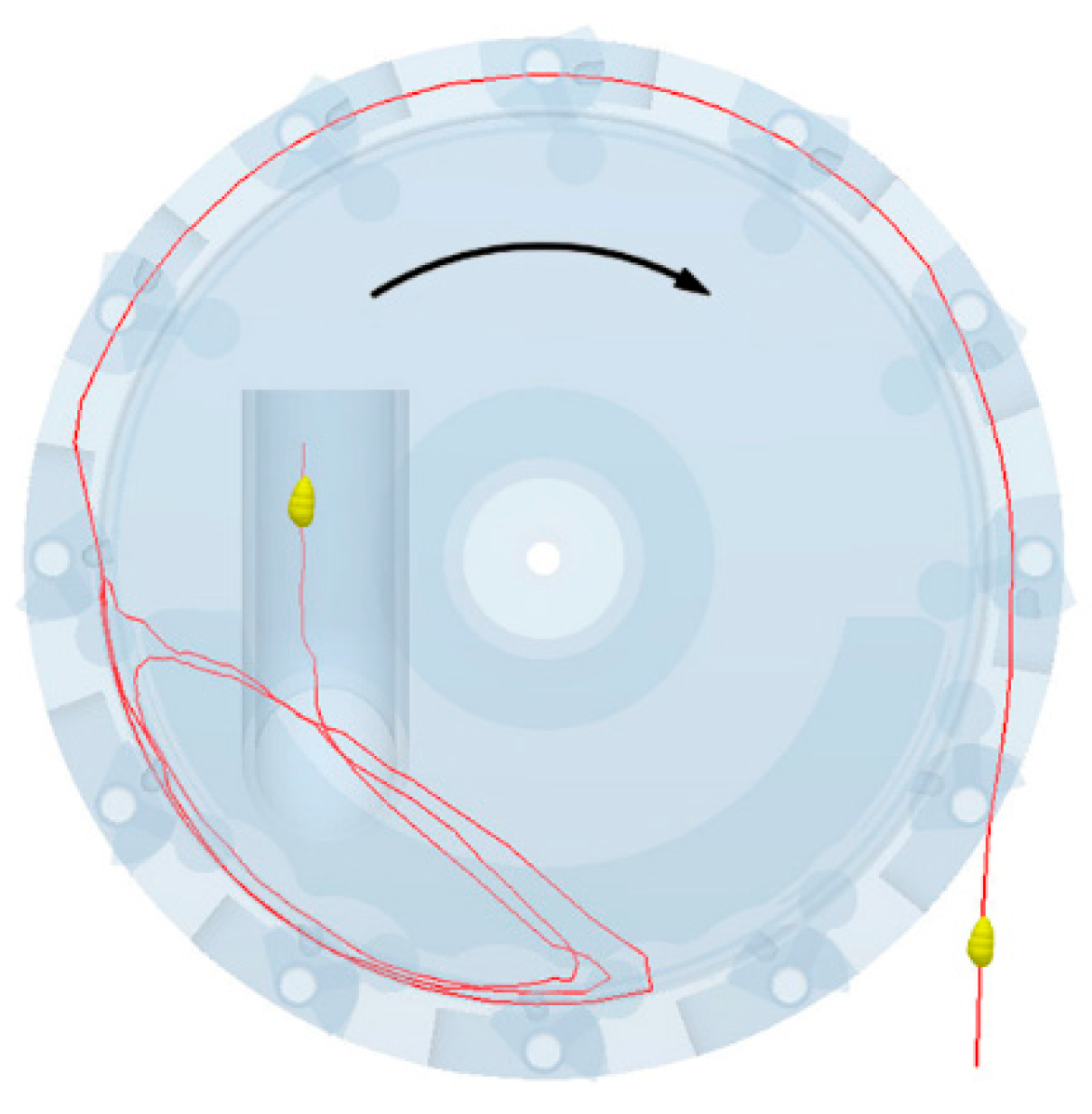
In EDEM, a cotton seed particle that has been successfully picked and discharged by the type-hole wheel is selected to generate the motion trajectory (Figure 6). The cotton seed enters the seed chamber from the seed drop tube, follows the rotation of the conveyor belt, and revolves with the seed group. It then moves from the bottom to the top of the conveyor belt, falls back to the bottom, and enters the hole of the type-hole wheel. When the hole of the type-hole wheel rotates back to the seed storage bin, the cotton seed reaches the seed storage bin and is discharged under the action of gravity.

3. Simulation and Bench Tests

3.1. Simulation Test

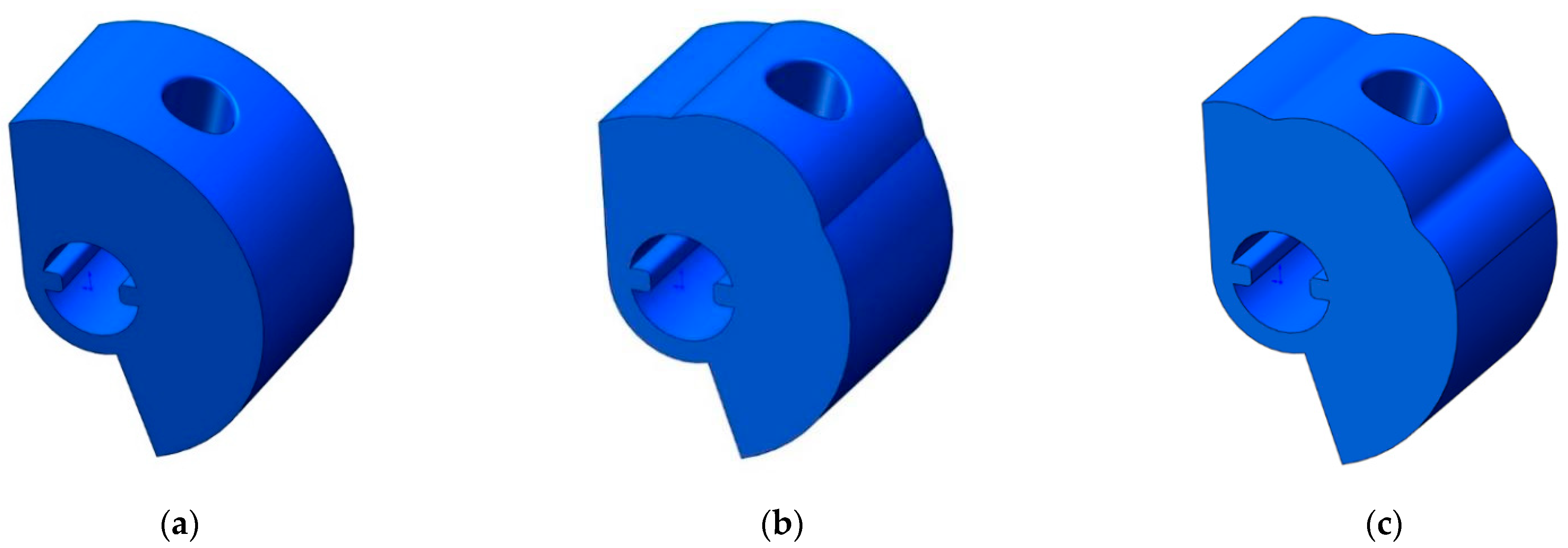
The theoretical analysis in Section 2.2 reveals that the type-hole wheel structure has a certain disturbance effect on the seed population, and increasing the disturbance of the population can improve the probability of successful seed filling in the type-hole. To study the effect of the type-hole wheel structure on the seed population inside the seed cavity, this study designed three type-hole wheel structures, namely, a circular-type-hole wheel, a convex-type-hole wheel, and a corrugated-type-hole wheel. The basic structural parameters of these three type-hole wheels are the same, with a hole diameter of 7.0 mm and a depth of 10.0 mm. The convex and corrugated seed wheels have a surface wave amplitude of 2.0 mm, and a rounded corner is made at the upper edge of the shape hole with a radius of 0.5 mm (Figure 7). The dibbler speed, number of gear plate teeth, and vibration amplitude of the type-hole wheel are set as 20 r/min, 6, and 10 mm, respectively, and the working speed of the dibbler is controlled by setting the rotation speed of the belt.
The vibration frequency and oscillation amplitude of the type-hole wheel influence the cotton seed filling effect on the shape hole. In addition, the oscillation frequency corresponds to the number of teeth on the gear plate during the movement of the type-hole wheel in the seeding and clearing area, and the oscillation amplitude corresponds to the tooth surface fluctuation amplitude of the gear plate. To investigate the impact of the vibration frequency and oscillation amplitude of the type-hole wheel on the seeding performance of the dibbler, we design a simulation test plan based on an optimized design of the combined experimental method. The test plan is used to determine the combination of type-hole wheel motion parameters that can achieve the best seeding performance. The type-hole wheel structure is corrugated, and based on preliminary experiments, the type-hole wheel oscillation amplitude is selected as 8–12 mm and the number of gear plate teeth is 4–8 (Figure 8).
To reduce the impact of the rotation speed on the seed population of the dibbler, the seeder rotation speed of 10–30 r/min was selected and the levels of seeding experiment factors were encoded (Table 2).
The simulation planting operation status has three key forms, namely single seeding (1 seed), double seeding (≥2 seeds), and missed seeding (no seed). To facilitate the observations of cotton seed movements, during the EDEM simulation process, only cotton seed particles within the seed disc thickness in the seed metering device are selected during seed retrieval. Moreover, the transparency of all mechanical components is set to 0.1 (Figure 9). Figure 9a depicts the qualified sowing state, where the type-hole wheel typically takes out a single cotton seed from the group of seed particles and transfers it to the seed storage bin through the type hole. Figure 9b shows the re-sowing state, where the type-hole wheel takes out multiple cotton seeds from the group of seed particles and transfers them to the seed storage bin through the seed-type hole. The cotton seed status in the type holes under multiple double-seeding states reveals that smaller cotton seeds are more prone to double-seeding. This is because when the size of cotton seeds around the type hole is small, it is easier for two or more cotton seeds to enter the hole under their own gravity and the compression of other cotton seeds. This makes it difficult for the seed cleaning plate to remove them from the type hole. Furthermore, in the double seeding state, the two cotton seeds in the type hole are mostly overlapping. Figure 9c presents the skip sowing state, where the type-hole wheel fails to smoothly remove the cotton seed from the group of seed particles. The cotton seed status around the type hole under multiple missed seeding states indicates that larger cotton seeds are more likely to experience missed seeding. This is because when the size of the cotton seeds around the type hole is large, the cotton seeds have difficulty entering the type hole under their own gravity and the compression of other cotton seeds, leading to unsuccessful seed retrieval. In addition, when a cotton seed is about to enter the type hole, it escapes from the hole due to the compression of the surrounding cotton seeds, resulting in failed seed retrieval.
According to the national standards GB/T 6976-2005 ‘Test Methods for Single-Granule (Precision) Seeders’ and JB/T10293-2013 ‘Technical Conditions for Single-Granule (Precision) Seeders’, this study selects the qualified index Y1 (Y1 represents the degree of matching between the number of seeds successfully sown by the seeder in each seeding cycle and the theoretical number of seeds), re-sowing index Y2 (Y2 refers to the proportion of instances where more than one seed is sown at a single seeding point during a seeding cycle), and skip sowing index Y3 (Y3 indicates the proportion of instances where no seeds are sown at a seeding point during the seeding process) as simulation test indicators to evaluate the quality of the seed metering device operation. These indices are calculated as follows:
Y 1 = N n 1 n 2 N × 100 %
Y 2 = n 1 N × 100 %
Y 3 = n 2 N × 100 %
where N is the total number of cotton seeds counted in the experiment; n1 is the number of cotton seeds that have a distance with adjacent seeds less than 0.5 times the theoretical seed distance; and n2 is the number of cotton seeds that have a distance with adjacent seeds greater than 1.5 times the theoretical seed distance.

3.2. Bench Test

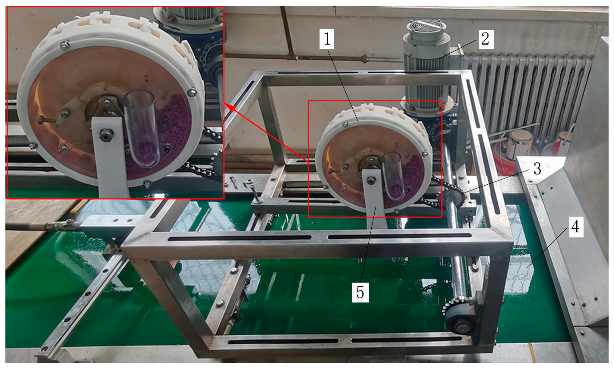
The JPS-12 seed metering device developed by the Heilongjiang Agricultural Machinery Research Institute was employed for the seeding performance test (Figure 10). During the test, the designed hole-type cotton seed metering device is installed on the test stand and the seedbed conveyor belt moves in the opposite direction to the seed metering device to simulate the actual field operation process. Cotton seeds are collected by the seed metering device and seeded on the seedbed conveyor belt coated with sticky oil to prevent the cotton seeds from bouncing on the seedbed conveyor belt. The image acquisition system of the test stand detects the cotton seeds in real-time to determine various seeding performance indicators and subsequently outputs the test results.
To validate the accuracy of the optimized simulation test results, the optimal parameter combination obtained from the simulation seeding test was used to create a gear plate, with a tooth number of 5.64 and a type-hole wheel swing amplitude of 9.71 mm. The components of the seeder were 3D printed using light-sensitive resin. Transparent resin materials were used for the seed-dropping tube and end cover to observe the seed movement inside the seeder. Xinlu Zhong 67 deseeded cotton seeds were selected for the experimental sample. The seeding device speeds were set to 12 r/min, 16 r/min, 20 r/min, 24 r/min, and 28 r/min for the seeding tests. In each test group, the number of seeding measurements was set to 250 (except for the start-up and stop phases), and each test group was repeated three times.

4. Results and Discussion

4.1. Impact of the Type-Hole Wheel Structure on the Seeding Performance

Figure 11 presents the vector diagram of the compression force of cotton seeds at 5.6 s when the rotational speed of the planter is 20 r/min. At this same time, the corrugated-type-hole wheel exhibits the maximum cotton seed compression force, reaching 0.317 N, followed by the convex-type-hole wheel (0.299 N) and the circular-type-hole wheel (0.212 N). The cotton seeds in the seed chamber of the circular-type-hole wheel generally move clockwise around the center. The cotton seeds at the bottom of the cotton seed group move to the upper right under the drive of the belt, and after reaching the top, they slide down to the left along the upper surface under the action of gravity and friction. The cotton seeds in the middle of the cotton seed group move clockwise under the drive of the upper and lower layer cotton seeds. The movement of the upper and lower layer cotton seeds in the seed chamber of the convex and corrugated-type-hole wheels is similar to that of the circular wheel. However, the movement of the cotton seeds in the middle of the cotton seed group exhibits an irregular trend, with a chaotic movement direction in some areas. Compared to the circular-type-hole wheel, the movements caused by the convex and corrugated-type-hole wheels are more irregular, indicating that they exert the greatest disturbance to the cotton seed particles, which is conducive to the filling of type holes by the cotton seeds.
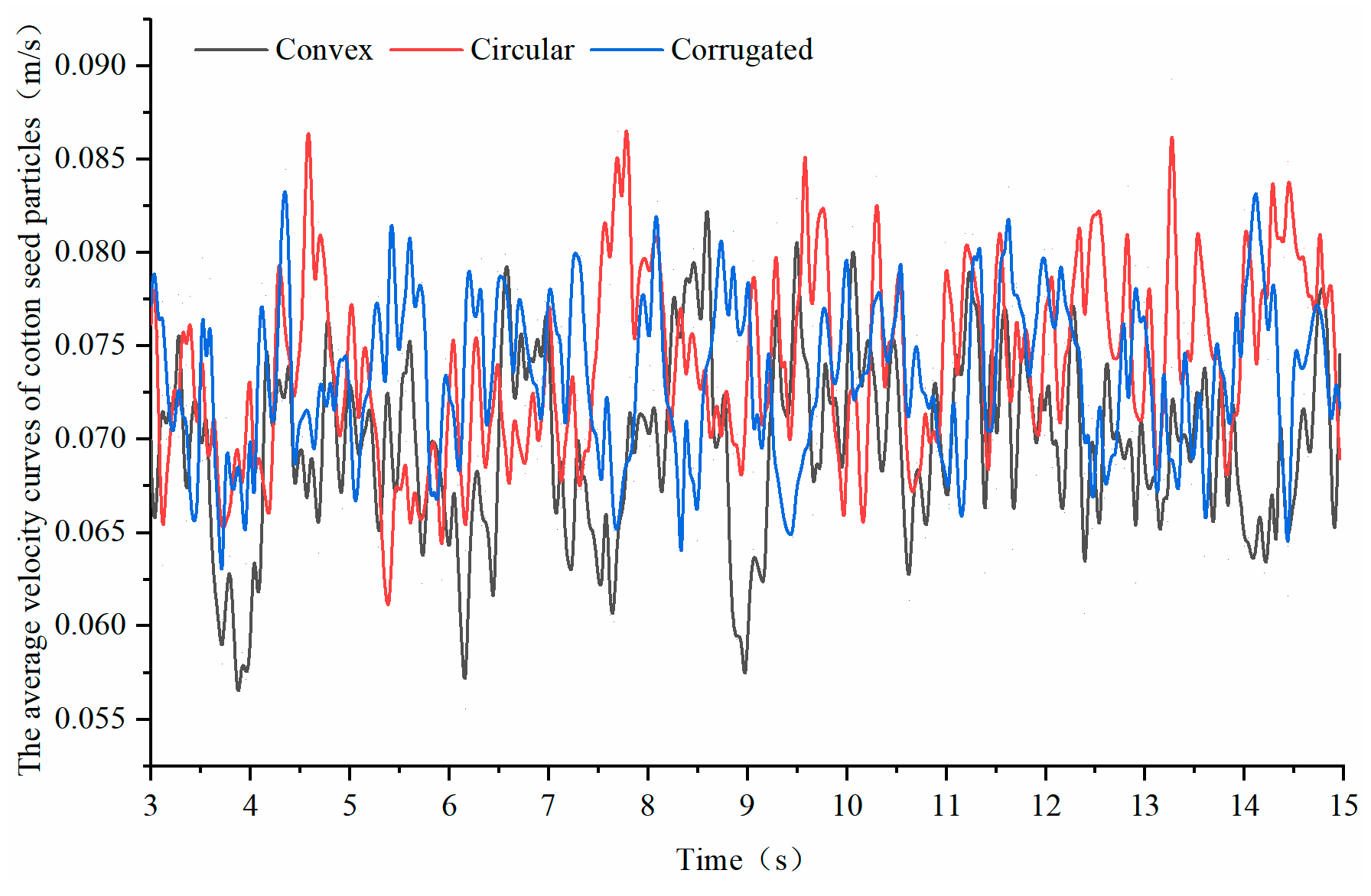
To further analyze the influence of the seeding wheel structure on the seeding process, the average velocity curves of cotton seed particles within the time steps of 3 to 15 s are shown in Figure 12. The cotton seed particle velocity with the circular-type-hole wheel is markedly lower than that of the convex and corrugated types. The fluctuation magnitude of the cotton seed particle velocity, from the largest to smallest, is as follows: convex-type-hole wheel (0.0284 m/s); circular-type-hole wheel (0.0276 m/s); and corrugated-type-hole wheel (0.0242 m/s). The relative velocity of cotton seed particles with the circular-type-hole wheel is low and the velocity fluctuates greatly. Although the convex-type-hole wheel can increase the relative velocity of the cotton seed particles, its velocity also exhibits large fluctuations. In contrast, the corrugated-type-hole wheel enhances the relative velocity of cotton seed particles while maintaining velocity fluctuations at a low level. This indicates the ability of the corrugated-type-hole wheel to improve the dibbler filling performance.
Therefore the structure of the type-hole wheel determines the mobility and compression force inside the dibbler. A well-designed type-hole wheel structure can effectively reduce the compression force between seeds, and increase the mobility of seeds, thereby improving filling efficiency. If the type-hole wheel structure is not optimized, the seeds may be subjected to excessive compression force, leading to seed damage or inadequate filling, which will further affect the quality and efficiency of seeding.

4.2. Influence of the Dibbler Rotation Speed on Seeding Performance

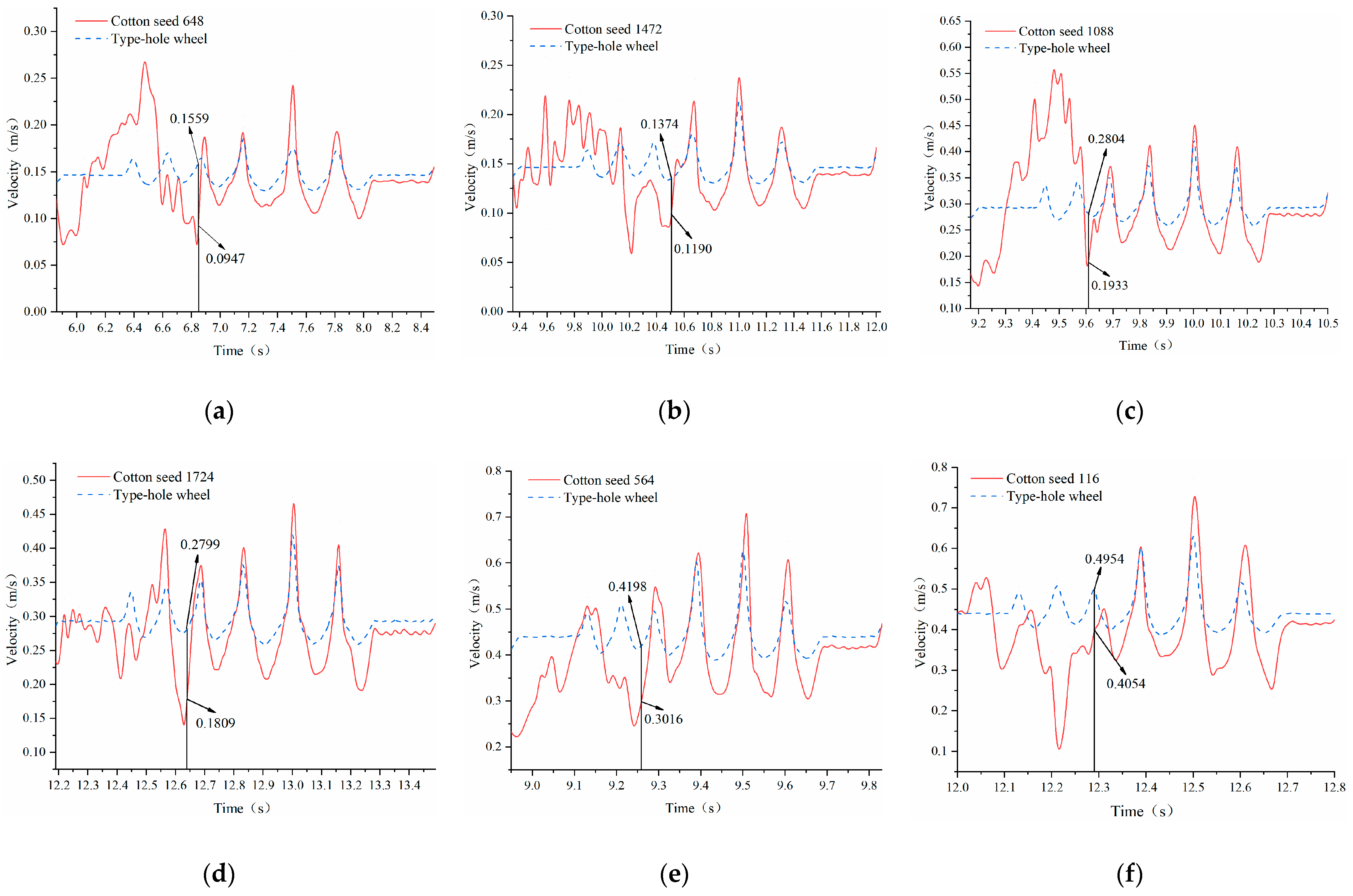
To analyze the relationship between the speed of the type-hole wheel and the cotton seeds during the seed-picking process, two cotton seeds successfully filled into the type holes were randomly selected. When the dibbler rotation speed was 10 r/min, the selected seed numbers were 648 and 1472; when the planter rotation speed was 20 r/min, the selected seed numbers were 1088 and 1724; when the planter rotation speed was 30 r/min, the selected seed numbers were 564 and 116. The cotton seeds were marked in EDEM to obtain the speed of the cotton seeds and the corresponding type-hole wheels during the seed-picking process. The data were plotted using Origin 2018 (OriginLab Corporation, Indianapolis, United States) to present the speed change trends of the cotton seeds and the corresponding type-hole wheels at different rotation speeds, as shown in Figure 13.
Figure 13a,b reveal that when the dibbler rotation speed is 10 r/min, the duration of the type-hole wheel in the seed picking and cleaning area is approximately 2.65 s, with the speed fluctuating between 0.12 and 0.23 m/s. The time taken for cotton seeds no. 648 and no. 1472 to fill into the holes is 6.84 s and 10.52 s, with speeds of 0.0947 m/s and 0.1190 m/s, respectively. At this time, the corresponding speeds of the type-hole wheel are 0.1559 m/s and 0.1374 m/s, respectively. Under a rotation speed of 10 r/min, the speed fluctuation range of successfully picked cotton seeds is between 0.05 and 0.27 m/s, with the speed of the cotton seeds before filling into the holes generally higher than that of the type-hole wheel.
Figure 13c,d show that when the dibbler rotation speed is 20 r/min, the duration of the type-hole wheel in the seed picking and cleaning area is approximately 1.33 s, with the speed fluctuating between 0.25 and 0.45 m/s. The time taken for cotton seeds no. 1088 and no. 1724 to fill into the holes is 9.61 s and 12.64 s, with speeds of 0.1933 m/s and 0.1809 m/s, respectively. At this time, the corresponding speeds of the type-hole wheel are 0.2804 m/s and 0.2799 m/s, respectively. Under a rotation speed of 20 r/min, the speed fluctuation range of successfully picked cotton seeds is between 0.13 and 0.48 m/s, and the of the cotton seeds before filling into the holes is generally still higher than that of the type-hole wheel.
Figure 13e,f reveal that when the dibbler rotation speed is 30 r/min, the duration of the type-hole wheel in the seed picking and cleaning area is approximately 0.88 s, with the speed ranging from 0.37 to 0.66 m/s. The time taken for cotton seeds no. 564 and no. 116 to fill into the holes is 9.26 s and 12.28 s, with speeds of 0.3016 m/s and 0.4054 m/s, respectively. At this time, the corresponding speeds of the type-hole wheel are 0.4198 m/s and 0.4954 m/s, respectively. Under a rotation speed of 30 r/min, the speed fluctuation range of successfully picked cotton seeds is between 0.11 and 0.73 m/s, and the speed of the cotton seeds before filling into the holes is mostly lower than that of the type-hole wheel.
In summary, as the dibbler rotation speed increases, the duration of the type-hole wheel in the seed picking and cleaning area decreases, while the speed fluctuation range of the cotton seeds increases. Under the same dibbler rotation speed, the variation in the type-hole wheel speed is constant, but the cotton seed speed exhibits irregular random fluctuations. At different planter rotation speeds, a higher rotation speed results in a larger instantaneous speed of the cotton seeds. Before filling into the holes of the type-hole wheel, the speed changes are relatively chaotic and fluctuate greatly. However, after filling the holes, the speed of the cotton seeds follows a similar trend to that of the type-hole wheel speed, but with a larger speed fluctuation range than the type-hole wheel. After filling the holes, in addition to moving with the type-hole wheel, the cotton seeds also move within the holes. An improved planting effect is achieved when the relative speed between the cotton seeds and the type-hole wheel is smaller. Therefore, by adjusting the dibbler rotation speed, the relative speed of the cotton seeds within the dibbler can be changed, thereby improving the effectiveness of filling the cotton seeds into the holes.

4.3. Effects of the Motion Parameters of the Type-Hole Wheel on Seeding Performance

Based on the actual production situation, the qualified index Y1, re-sowing index Y2, and skip-sowing index Y3 were selected as the experimental indicators for planting experiments. Table 3 reports the design of the Box–Behnken response surface experiment and the corresponding results.
We employed Design-Expert 12.0 (Stat-Ease Inc., Minia Bonis, Minneapolis, MN, USA) to conduct polynomial regression analysis on the seeding experiment results. The second-order polynomial regression models for the qualified index, re-sowing index, and skip-sowing index are expressed in Equations (13)–(15):
Y 1 = 91.78 1.92 X 1 0.48 X 2 0.56 X 3 + 0.17 X 1 X 2 0.48 X 1 X 3 0.40 X 2 X 3 1.66 X 1 2 1.82 X 2 2 1.50 X 3 2
Y 2 = 3.96 0.91 X 1 + 0.66 X 2 0.01 X 3 0.03 X 1 X 2 + 0.01 X 1 X 3 + 0.45 X 2 X 3 + 0.86 X 1 2 + 1.01 X 2 2 + 0.72 X 3 2
Y 3 = 4.26 + 2.71 X 1 0.19 X 2 + 0.45 X 3 0.13 X 1 X 2 + 0.22 X 1 X 3 0.05 X 2 X 3 + 0.67 X 1 2 + 0.93 X 2 2 + 0.66 X 3 2
Table 4, Table 5 and Table 6 report the results of the regression model variance analysis. The p-values of the regression models for the three indices are less than 0.0001, and the p-values of the lack-of-fit terms exceed 0.05. This indicates that the regression models are highly significant, the lack-of-fit of the models is not significant, and the regression models have a high fitting degree.
Table 4 reveals that the interaction terms (X1X2, X1X3, and X2X3) between the rotation speed of the dibbler, the number of teeth on the gear plate, and the oscillation amplitude of type-hole wheel do not exert a significant influence (p > 0.05) on the qualified index model, while all other factors have a significant impact on the qualified index model. Table 5 indicates that the oscillation amplitude of the type-hole wheel does not significantly affect the re-sowing index model (p > 0.05), suggesting that the oscillation amplitude of the type-hole wheel has a minor impact on the re-sowing index. In addition, the interaction terms (X1X2, X1X3, and X2X3) between the rotation speed of the dibbler, the number of teeth on the gear plate, and the oscillation amplitude of the type-hole wheel also do not significantly influence (p > 0.05) the re-sowing index model, while all other factors have a significant impact on the re-sowing index model. Table 6 shows that the interaction term (X1X2) between the rotation speed of the dibbler and the number of teeth on the gear plate and the interaction term (X2X3) between the number of teeth on the gear plate, and the oscillation amplitude of type-hole wheel do not significantly impact (p > 0.05) the skip sowing index model, while all other factors have a significant impact on the skip sowing index model.
Removing the non-significant terms from the regression models of the qualified index, re-sowing index, and skip-sowing index results in the following simplified equations, respectively:
Y 1 = 91.78 1.92 X 1 0.48 X 2 0.56 X 3 1.66 X 1 2 1.82 X 2 2 1.50 X 3 2
Y 2 = 3.96 0.91 X 1 + 0.66 X 2 0.01 X 3 + 0.86 X 1 2 + 1.01 X 2 2 + 0.72 X 3 2
Y 3 = 4.26 + 2.71 X 1 0.19 X 2 + 0.45 X 3 + 0.22 X 1 X 3 + 0.67 X 1 2 + 0.93 X 2 2 + 0.66 X 3 2
After simplification, the goodness of fit R2 for the regression models of the qualified index, re-sowing index, and skip-sowing index are 0.9603, 0.9960, and 0.9166, respectively. This indicates that the predicted values of the regression model equations have a good fit with the actual values. Thus, the regression models for the seed selection qualified index, re-broadcast index, and missed broadcast index have high reliability.
To obtain the optimal parameter combination for the rotation speed of the dibbler, the number of teeth on the gear plate, and the oscillation amplitude of the type-hole wheel, this study takes the maximum value of the qualified index, and the minimum values of the re-sowing index and skip sowing index as the optimization objectives. The optimization objectives and constraints for the rotation speed of the dibbler, the number of teeth on the gear plate, and the oscillation amplitude of the type-hole wheel can be formulated as Equation (19):
max Y 1 ( X 1 , X 2 , X 3 ) min Y 2 ( X 1 , X 2 , X 3 ) , Y 3 ( X 1 , X 2 , X 3 ) 10 X 1 30 4 X 2 8 7 X 3 13
The optimization module of Design-Expert 12.0 is used to optimize the constrained objective function, obtaining the best parameter combination can be obtained. At the dibbler rotation speed of 16.34 r/min, the number of teeth on the gear plate is 5.64, the oscillation amplitude of the type-hole wheel is 9.71 mm, and the seeding performance of the seed planter reaches is optimized. At this point, the qualified index is 92.23%, the re-sowing index is 3.63%, and the skip-sowing index is 4.18%.

4.4. Optimization and Validation of Seeder Performance in Bench Tests

The qualified index, re-sowing index, and skip-sowing index were selected as the evaluation criteria for seeding performance. Table 7 presents the bench test results.
The experimental results presented in Table 7 show that as the dibbler rotation speed increases, the qualified index initially increases and then decreases, while the re-sowing index exhibits a decreasing trend and the skip-sowing index exhibits an increasing trend. As the rotation speed increases, the movement of seeds inside the seeder accelerates, improving filling efficiency and increasing the qualified index. However, when the speed increases further, the effect of centrifugal force becomes more pronounced, causing some seeds to fail to enter the seeding holes properly, which leads to a decrease in filling efficiency and a subsequent decline in the qualified index. When the rotation speed of the dibbler reaches 16 r/min, the qualified index reaches its maximum value of 93.28%, with the skip-sowing index at 2.37% and the re-sowing index at 4.35%. The qualified index from the bench test is slightly higher than that from the simulation test. This discrepancy may be attributed to the vibrations caused by the rotation of the motor and the chain gear transmission in the bench test, which intensifies the seed movement within the seeder and facilitates seed filling in the seed extraction wheel. The relative error between the bench test and simulation test results is not significant, indicating that the simulation test results are relatively accurate.

5. Conclusions

A simulation model of a type-hole wheel precision cotton dibbler was established based on the DEM-MBD-coupled algorithm to analyze the impact of the type-hole wheel structure and the motion parameters of the dibbler on its seed extraction and seeding performance. The main conclusions are as follows:
(1) Three different structures of the type-hole wheel were designed: circular; convex; and corrugated. The effects of the type-hole wheel structural designs and operating speed on the dibbler seeding performance were analyzed. The results showed that the average movement speed of the cotton seed particles in the seed chamber increased with the dibbler rotation speed. Among the three structures, the corrugated-type-hole wheel caused the greatest disturbance to the cotton seed population within the dibbler. In particular, the corrugated-type-hole wheel type increased the relative speed of the cotton seed particles and the seed population speed fluctuated less compared to the other type-hole wheel types, indicating it to be more conducive to filling the holes with the seeds.
(2) A combination design experiment was conducted to study the optimal motion parameter combination for the type-hole wheel and establish a mathematical model relating the seeding performance indicators to the experimental parameters. The rotation speed of the dibbler, the number of teeth on the gear plate, and the oscillation amplitude of the type-hole wheel were selected as experimental factors, and the qualified index, re-sowing index, and skip-sowing index were used as evaluation criteria. The regression mathematical model was optimized, yielding the following optimal parameter combination: dibbler rotation speed of 16.34 r/min; the number of gear plate teeth of 5.64; and type-hole wheel oscillation amplitude of 9.71 mm.
(3) A bench test of the seeder’s seeding performance was conducted. The test results indicated that when the rotation speed of the dibbler was 16 r/min, the qualified index reached a maximum value of 93.28%, with a re-sowing index of 4.35% and a skip-sowing index of 2.37%. The results from the bench test were consistent with those from the simulation test, showing that the re-sowing index decreased with the increase in rotation speed, while the skip-sowing index increased with the dibbler rotation speed.
This study presents significant advancements in the seeding performance of the dibbler, achieved by optimizing both the structure of the type-hole wheel and the motion parameters of the device. The findings demonstrate that variations in type-hole wheel design considerably influence seed movement and speed fluctuations. Although these parameters exhibited strong performance under controlled experimental conditions, they may be influenced by real-world factors, including terrain variations, differences in soil conditions, and the maintenance of equipment during operational use. Therefore, to ensure sustained optimal performance across diverse operating environments, regular maintenance of the dibbler is recommended, along with the adjustment of parameters tailored to specific conditions. Future research should consider additional variables to further refine and optimize the dibbler’s design, including the impact of seed type and shape, soil conditions, and fluctuations in the operational environment, thereby ensuring robust performance across a range of field conditions.

Author Contributions

Conceptualization, L.W. and H.L.; methodology, L.W. and X.R.; software, L.W. and X.R.; validation, L.W., X.W. and J.X.; formal analysis, L.S.; investigation, L.S. and X.R.; data curation, S.H.; writing—original draft preparation, L.W.; writing—review and editing, L.W. and H.L.; project administration, L.W. and H.L.; funding acquisition, L.W. All authors have read and agreed to the published version of the manuscript.

Funding

This research was supported by the Bintuan Science and Technology Program (2022CB001-06, 2023AB005-01) and the President Fund from Tarim University (TDZKYS202302).

Institutional Review Board Statement

Not applicable.

Data Availability Statement

The data presented in this study are available upon request from the authors.

Acknowledgments

The authors would like to thank their schools and colleges, as well as the funding providers of the project. All support and assistance are sincerely appreciated.

Conflicts of Interest

The authors declare no conflicts of interest.

References

  1. Zhang, X.; Wu, B.; Niu, L.K.; Xiong, X.Y.; Dong, Z.X. Dynamic characteristics of two-way coupling between flip-flow screen and particles based on DEM. Chin. Coal Soc. 2019, 44, 1930–1940. [Google Scholar]
  2. Gan, J.Q.; Zhou, Z.Y.; Yu, A.B.; Ellis, D.; Attwood, R.; Chen, W. Co-simulation of multibody dynamics and discrete element method for hydraulic excavators. Powder Technol. 2023, 414, 118001. [Google Scholar] [CrossRef]
  3. Fang, J.; Zhao, C.F.; Lu, X.Y.; Xiong, W.H.; Shi, C. Dynamic behavior of railway Vehicle-Ballasted track system with unsupported sleepers based on the hybrid DEM-MBD method. Constr. Build. Mater. 2023, 394, 132091. [Google Scholar] [CrossRef]
  4. Coetzee, C.J.; Els, D.N.J.; Dymond, G.F. Discrete element parameter calibration and the modelling of dragline bucket filling. J. Terramech. 2010, 47, 33–44. [Google Scholar] [CrossRef]
  5. Lommen, S.; Lodewijks, G.; Schott, D.L. Co-simulation framework of discrete element method and multibody dynamics models. Eng. Comput. 2018, 35, 1481–1499. [Google Scholar] [CrossRef]
  6. Lu, Z.; Lu, X.L.; Lu, W.S.; Masri, S.F. Studies of the performance of particle dampers under dynamic loads. J. Sound Vib. 2010, 329, 5415–5433. [Google Scholar] [CrossRef]
  7. Ahmad, N.; Ranganath, R.; Ghosal, A. Modeling and experimental study of a honeycomb beam filled with damping particles. J. Sound Vib. 2017, 391, 20–34. [Google Scholar] [CrossRef]
  8. Barrios, G.K.P.; Tavares, L.M. A preliminary model of high pressure roll grinding using the discrete element method and multi-body dynamics coupling. Int. J. Miner. Process. 2016, 156, 32–42. [Google Scholar] [CrossRef]
  9. Ji, S.Y.; Liang, S.M. DEM-FEM-MBD coupling analysis of landing process of lunar lander considering landing mode and buffering mechanism. Adv. Space Res. 2021, 68, 1627–1643. [Google Scholar] [CrossRef]
  10. Mohajeri, M.J.; de Kluijver, W.; Helmons, R.L.J.; van Rhee, C.; Schott, D.L. A validated co-simulation of grab and moist iron ore cargo: Replicating the cohesive and stress behaviour of bulk solids. Adv. Powder Technol. 2021, 32, 1157–1169. [Google Scholar] [CrossRef]
  11. Shi, S.W.; Gao, L.; Xiao, H.; Xu, Y.; Yin, H. Research on ballast breakage under tamping operation based on DEM-MBD coupling approach. Constr. Build. Mater. 2021, 272, 1810–1822. [Google Scholar] [CrossRef]
  12. Shi, S.W.; Gao, L.; Cai, X.P.; Yin, H.; Wang, X.L. Effect of tamping operation on mechanical qualities of ballast bed based on DEM-MBD coupling method. Comput. Geotech. 2020, 124, 103574. [Google Scholar] [CrossRef]
  13. Xiao, W.Q.; Huang, Y.X.; Jiang, H.; Lin, H.; Li, J.L. Energy dissipation mechanism and experiment of particle dampers for gear transmission under centrifugal loads. Particuology 2016, 27, 40–50. [Google Scholar] [CrossRef]
  14. Xiao, W.Q.; Li, J.N.; Pan, T.L.; Zhang, X.; Huang, Y.X. Investigation into the influence of particles’ friction coefficient on vibration suppression in gear transmission. Mech. Mach. Theory 2017, 108, 217–230. [Google Scholar] [CrossRef]
  15. Chung, Y.C.; Wu, Y.R. Dynamic modeling of a gear transmission system containing damping particles using coupled multi-body dynamics and discrete element method. Nonlinear Dyn. 2019, 98, 129–149. [Google Scholar] [CrossRef]
  16. Wu, Y.R.; Chung, Y.C.; Wang, I.C. Two-way coupled MBD-DEM modeling and experimental validation for the dynamic response of mechanisms containing damping particles. Mech. Mach. Theory 2021, 159, 104257. [Google Scholar] [CrossRef]
  17. Curry, D.R.; Deng, Y. Optimizing Heavy Equipment for Handling Bulk Materials with Adams-EDEM Co-simulation. In Proceedings of the 7th International Conference on Discrete Element Methods (DEM), Dalian, China, 15 December 2017. [Google Scholar]
  18. Hu, J.P.; Pan, J.; Chen, F.; Yue, R.C.; Yao, M.J.; Li, J. Simulation Optimization and Experiment of Finger-clamping Seedling Picking Claw Based on EDEM RecurDyn. Chin. Soc. Agric. Mach. 2022, 53, 75–85+301. [Google Scholar]
  19. Xu, T.Y.; Zhang, R.X.; Wang, Y.; Jiang, X.M.; Feng, W.Z.; Wang, J.L. Simulation and Analysis of the Working Process of Soil Covering and Compacting of Precision Seeding Units Based on the Coupling Model of DEM with MBD. Processes 2022, 10, 1103. [Google Scholar] [CrossRef]
  20. Yan, D.X.; Xu, T.Y.; Yu, J.Q.; Wang, Y.; Guan, W.; Tian, Y.; Zhang, N. Test and Simulation Analysis of the Working Process of Soybean Seeding Monomer. Agriculture 2022, 12, 1464. [Google Scholar] [CrossRef]
  21. Liu, Y.; Liu, Y.P.; Zhang, T. Load Analysis of Rotary Cutter Shaft for Power Tiller Based on DEM and MBD Theory. J. Agric. Sci. Technol. 2020, 22, 79–86. [Google Scholar]
  22. Lai, Q.H.; Jia, G.X.; Su, W.; Zhao, L.J.; Qiu, X.B.; Lu, Q. Design and Test of Chain Spoom Type Precision Seed Metering Device for Ginseng Based onDEM-MBD Coupling. Chin. Soc. Agric. Mach. 2022, 53, 91–104. [Google Scholar]
  23. Kim, Y.S.; Lee, S.D.; Baek, S.M.; Baek, S.Y.; Jeon, H.H.; Lee, J.H.; Siddique, M.A.; Kim, Y.J.; Kim, W.S.; Sim, T.; et al. Development of DEM-MBD coupling model for draft force prediction of agricultural tractor with plowing depth. Comput. Electron. Agric. 2022, 202, 107405. [Google Scholar] [CrossRef]
  24. Dong, X.Q.; Su, C.; Zheng, H.N.; Han, R.Q.; Li, Y.L.; Wan, L.P.C.; Song, J.N.; Wang, J.C. Analysis of soil disturbance process by vibrating subsoiling based on DEM-MBD coupling algorithm. Transact. Chin Soc. Agric. Eng. 2022, 38, 34–43. [Google Scholar]
  25. Yu, Q.X.; Liu, Y.; Chen, X.B.; Sun, K.; Lai, Q.H. Calibration and Experiment of Simulation Parameters for Panax notoginseng Seeds Based on DEM. Chin. Soc. Agric. Mach. 2020, 51, 123–132. [Google Scholar]
  26. Abbaspour-Fard, M.H. Theoretical validation of a multi-sphere discrete element model suitable for biomaterials handling simulation. Biosyst. Eng. 2004, 88, 153–161. [Google Scholar] [CrossRef]
  27. Wang, L.; He, X.W.; Hu, C.; Guo, W.S.; Wang, X.F.; Xing, J.F. Measurement of physical parameters of coated cotton seed and parameter calibration of discrete element. Chin. Agric. Univ. 2022, 27, 71–82. [Google Scholar]
  28. Wang, L.; Hu, C.; He, X.W.; Guo, W.S.; Hou, S.L. A general modelling approach for coated cotton-seeds based on the discrete element method. Inmateh-Agric. Eng. 2021, 63, 219–228. [Google Scholar]
Figure 1. Structure of the rotary type-hole dibbler. (1) Shaft, (2) seed tube, (3) dynamic ring, (4) waist belt, (5) duckbill dynamic plate, (6) spring, (7) duckbill fixed plate, (8) fixed plate, (9) gear plate, (10) moving plate, (11) shifter, (12) type-hole wheel, (13) torsion spring, (14) disrupter, (15) disrupter support frame, (16) sight hole cover plate, and (17) end cover.
Agriculture 14 01411 g001
Figure 2. Working principle of the rotary type-hole dibbler. (I) Seed picking and cleaning, (II) seed storage and dropping, (III) hole forming and seeding. (1) cotton seeds, (2) duckbill, (3) type-hole wheel, (4) dibbler, (5) soil on plastic film, (6) plastic film, and (7) soil under plastic film.
Agriculture 14 01411 g002
Figure 3. Motion state of the cotton seed falling into the type hole.
Agriculture 14 01411 g003
Figure 4. Processing of the coated cotton seed contour model: (a) coated cotton seed, (b) contour model, (c) multi-sphere aggregation particle model.
Agriculture 14 01411 g004
Figure 5. EDEM-RecurDyn-coupled simulation: (a) RecurDyn simulation; (b) EDEM simulation. The direction of the arrow indicates the direction of dibbler movement.
Agriculture 14 01411 g005
Figure 6. Motion trajectory of the cotton seed. Yellow represent cotton seed, and red lines represent the movement trajectory of cotton seed.
Agriculture 14 01411 g006
Figure 7. Different type-hole wheel structures designed in this study: (a) circular-type-hole wheel, (b) convex-type-hole wheel, (c) corrugated-type-hole wheel.
Agriculture 14 01411 g007
Figure 8. Gear plates of dibbler structures designed in this study: (a) Four teeth, (b) six teeth, (c) eight teeth.
Agriculture 14 01411 g008
Figure 9. EDEM virtual simulation of seed sowing operation status: (a) qualified sowing state, (b) re-sowing state, (c) skip sowing state. The regions between red dashed lines represent seed sowing operation status.
Agriculture 14 01411 g009
Figure 10. Seed planting performance evaluation test; (1) the rotary type-hole dibbler, (2) the motor, (3) the transmission shaft, (4) the conveyor belt, and (5) the fixed bracket. The red boxes and arrow represent enlarged view of the dibbler.
Agriculture 14 01411 g010
Figure 11. Vector plot of the cotton seed compression force at 5.6 s: (a) circular-type-hole wheel, (b) convex-type-hole wheel, (c) corrugated-type-hole wheel.
Agriculture 14 01411 g011
Figure 12. Average velocity of cotton seed particles under the action of different type-hole wheels with different structures.
Agriculture 14 01411 g012
Figure 13. Speed of cotton seeds and type-hole wheels at different rotation speeds: (a) cotton seed 648 with the dibbler rotation speed at 10 r/min, (b) cotton seed 1472 with the dibbler rotation speed at 10 r/min, (c) cotton seed 1088 with the dibbler rotation speed at 20 r/min, (d) cotton seed 1724 with the dibbler rotation speed at 20 r/min, (e) cotton seed 564 with the dibbler rotation speed at 30 r/min, and (f) cotton seed 116 with the dibbler rotation speed at 30 r/min.
Agriculture 14 01411 g013
Table 1. Simulation model parameters.
ParameterValue
Density of cotton seed (g/cm3)0.981
Poisson’s ratio of cotton seed0.27
Shear modulus of cotton seed (MPa)1.4 × 10⁷
Density of resin (g/cm3)1.18
Poisson’s ratio of resin0.38
Shear modulus of resin (MPa)177
Seed-to-seed static friction coefficient0.130
Seed-to-seed dynamic friction coefficient0.225
Seed-to-seed collision restoration coefficient0.185
Seed-to-resin static friction coefficient0.49
Seed-to-resin dynamic friction coefficient0.21
Seed-to-resin collision restoration coefficient0.25
Table 2. Encoding of the seeding experiment factor levels.
LevelRotation Speed of Dibbler
X1 (r/min)
Number of Teeth on the Gear Plate
X2
Oscillation Amplitude of the Type-Hole Wheel
X3 (mm)
−11047
020610
130813
Table 3. Design and results of the seeding experiment.
No.Rotation Speed of Dibbler
X1 (r/min)
Number of Teeth on the Gear Plate
X2
Oscillation Amplitude of Type-Hole Wheel
X3 (mm)
Qualified
Index
Y1 (%)
Re-Sowing Index
Y2 (%)
Skip Sowing Index
Y3 (%)
1−11089.697.253.06
20−1−189.165.395.45
30−1189.224.166.62
4−10190.436.523.05
501−188.486.345.18
600091.653.884.47
700091.574.324.11
81−1086.584.498.93
901186.966.896.15
1000091.524.214.27
1110−187.774.547.69
1210185.314.858.84
13−10−190.966.262.78
1400092.193.754.06
15−1−1090.456.383.17
1611086.485.238.29
1700091.963.654.39
Table 4. Analysis of variance for the qualified index.
Source of VarianceSum of SquaresDegrees of
Freedom
FpSignificance
Model74.67942.97<0.0001**
X129.611153.33<0.0001**
X21.8119.350.0184*
X32.48112.820.0090**
X1X20.108910.56400.4771
X1X30.931214.820.0641
X2X30.624113.230.1152
X1X111.57159.930.0001**
X2X213.95172.25<0.0001**
X3X39.51149.240.0002**
Residual1.357
Lack of fit1.0234.140.1017
Error0.32914
Sum76.0216
Note: ** denotes an extremely significant impact of the parameter (p < 0.01); and * represents a significant impact of the parameter (p < 0.05). The same as Table 5 and Table 6.
Table 5. Analysis of variance for the re-sowing index.
Source of VarianceSum of SquaresDegrees of
Freedom
FpSignificance
Model21.69915.290.0008**
X16.66142.260.0003**
X23.50122.190.0022**
X30.001510.00960.9247
X1X20.004210.02680.8746
X1X30.000610.00400.9516
X2X30.792115.030.0599
X1X13.12119.820.0030**
X2X24.33127.460.0012**
X3X32.18113.810.0075**
Residual1.107
Lack of fit0.764733.010.1574
Error0.33874
Sum22.7916
Table 6. Analysis of variance for the skip sowing index.
Source of VarianceSum of SquaresDegrees of
Freedom
FpSignificance
Model69.159270.38<0.0001**
X158.8112069.37<0.0001**
X20.277519.770.0167*
X31.58155.750.0001**
X1X20.070212.470.1599
X1X30.193616.810.0349*
X2X30.010010.35190.5717
X1X11.90166.76<0.0001**
X2X23.651128.49<0.0001**
X3X31.83164.30<0.0001**
Residual0.19897
Lack of fit0.075330.81260.5498
Error0.12364
Sum69.3516
Table 7. The bench test results.
Rotation Speed of the
Dibbler (r/min)
Qualified Index (%)Re-Sowing Index (%)Skip Sowing Index (%)
1291.786.641.58
1693.284.352.37
2092.953.983.07
2492.173.044.79
2890.712.826.47
Disclaimer/Publisher’s Note: The statements, opinions and data contained in all publications are solely those of the individual author(s) and contributor(s) and not of MDPI and/or the editor(s). MDPI and/or the editor(s) disclaim responsibility for any injury to people or property resulting from any ideas, methods, instructions or products referred to in the content.