Abstract
To address the problem of large tractive resistance in traditional subsoiling methods, this paper designed a pulse-type gas explosion subsoiler, as well as an air-blown double-ended chisel type subsoiling shovel and a conduit. The mathematical equation of the influence of the structural parameters of the subsoiler on the groove profile is established. The EDEM 2022 software was used to simulate the subsoiling operation process. The soil disturbance law of the chisel subsoiler was analyzed by the change of soil particle velocity. The optimum value interval of quadratic regression orthogonal rotation combination test factors was determined by using the steepest climb test, with specific tillage resistance and filling power as evaluation indicators. Based on the Box–Behnken design test, a second-order regression model of response value and significance parameter was obtained, and an optimal combination was found by optimizing the significance parameter. The effects of subsoiling air pressure, pulse width and pulse interval on evaluation indicators were analyzed by the response surface method; the test results show that when the air pressure was 0.8 MPa, the pulse width was 0.17 s and the pulse interval was 0.12 s, and the specific tillage resistance was 0.4421 N/mm2 and the filling power was 18.5%; a comparative test between the pulse-type gas explosion subsoiler and a continuous gas explosion subsoiler was carried out, and the specific tillage resistance was reduced by 12.2% and the filling power was reduced by 10.5%; the comparative test shows that the pulse-type gas explosion subsoiler has smaller tractive resistance per unit area and smaller disturbance to soil. The research results provide a theoretical basis and reference for the optimization and improvement of gas explosion subsoilers.
1. Introduction
Traditional farming methods and the use of agricultural machinery have caused soil compaction, which has formed a thick and hard plough layer on the cultivated land [1]. The plough bottom has great solidity which affects the root development and slows down the yield of crops [2,3]. At the same time, the surface runoff is caused by slowing down the infiltration rate of rainwater, which leads to the decrease in surface nutrients [4,5]. As one of the core technologies of conservation tillage, subsoiling has been used to eliminate soil compaction and restore soil productivity [6,7].
Subsoiling technology mainly includes natural, chemical, biological and mechanical methods [8,9,10]. Natural subsoiling and biological subsoiling methods require a long-term process that may affect crop production. Chemical subsoiling has little effect on crop growth, but it may cause soil and environmental pollution. Mechanical subsoiling technology often uses a subsoiler to cut and destroy the soil of cultivated land to subsoil the soil. Compared with the other two methods, it has the advantages of fast operation speed, strong controllability and good effect. Therefore, the application range of mechanical subsoiling is also the most extensive. In order to break the plow pan completely, the subsoiling shovel should plow much deeper than other farming machines do. To tackle the problems of large tractive resistance and high matching power requirements, domestic and foreign workers have conducted in-depth research on resistance reduction technology of the subsoiler [11,12].
In recent years, the pneumatic splitting principle has been used at home and abroad to crack soil and increase air flow channels, thus reducing tractive resistance. Araya et al. [13,14] installed a high-pressure jet device on the subsoiler, allowing the surface of the subsoiling shovel to eject air during operation to achieve the effects of subsoiling and soil breaking; Zuo S.J et al. [15] proposed pneumatic subsoiling based on the pneumatic splitting technology, that is, injecting high pressure air into cultivated soil to form cracks in the soil so as to achieve soil subsoiling, and also explored the change law of soil surface lift and porosity before and after the test; Su H J [16] designed an air-blown subsoiler, analyzed the disturbance behavior of the air-blown subsoiling shovel on soil through coupling simulation, and verified the resistance reduction effect of the subsoiler through a soil tank test; Chen J C [17] designed a gas explosion soil ripper suitable for orchard root soil loosening, and optimized the design of the drill pipe structure through coupling simulation; Tu J et al. [18] proposed a fixed-point soil subsoiling method based on pulse gas explosion, and designed a continuous spiral soil insertion device. In addition, Zhao S H et al. [19] designed a subsoiling shovel with a fitted curve based on a discrete element simulation test analysis of the shovel tip motion of the subsoiling shovel. Zou L L et al. [20] and Wang Yun X et al. [21] designed a subsoiling shovel with an actively lubricated and resistance-reducing surface and a subsoiling shovel with hydraulic excitation, respectively. In summary, researchers have carried out a lot of research by using theoretical analysis, finite element and discrete element methods [22,23,24], but the effect of pulse gas on the resistance reduction of the subsoiler was seldom reported.
Based on the above studies, this paper designed a pulse-type gas explosion subsoiler, combining the principle of pulse gas explosion and double-ended chisel type subsoiler. It is mainly composed of a subsoiling shovel, a pulse controller, a solenoid valve and a depth limiting wheel. During operation, the subsoiling shovel uses a pulse air flow to lift soil, thus achieving the purpose of reducing tractive resistance. The mathematical equation of the influence of the structural parameters of the subsoiler on the groove profile is established. The finite element model of the chisel-shaped subsoiler and the discrete element model of the soil bin were established. The EDEM software was used to simulate the subsoiling process. The soil disturbance law of the chisel-shaped subsoiler was analyzed by the change of particle velocity. Multi-factor tests were conducted with specific tillage resistance and filling power as evaluation indicators. Subsoiling air pressure, pulse width, pulse interval and other parameters were optimized. The research results are expected to provide a theoretical basis and reference for the optimization and improvement of gas explosion subsoilers.
2. Materials and Methods
2.1. Overall Structure and Working Principle of Pulse-Type Gas Explosion Subsoiler
2.1.1. Overall Structure
The structure of the pulse-type gas explosion subsoiler is as shown in Figure 1, which is mainly composed of a subsoiling shovel, an air compressor, a pulse controller, a solenoid valve, a depth limiting wheel and a rack. The subsoiling shovel and depth limiting wheel are connected to the rack through U-shaped buckles, the air release valve of the air compressor is connected to the solenoid valve air supply port through an adapter, and the air outlet of the solenoid valve is connected to the subsoiling shovel conduit through pneumatic quick coupling.
Figure 1.
Structural diagram of the pulse-type gas explosion subsoiler. 1. Air compressor; 2. Frame; 3. Subsoiling shovel; 4. Limit wheel; 5. Conversion connector; 6. Solenoid valve; 7. Pneumatic quick coupling. 8. Shovel tip; 9. Jet exhaust; 10. Subsoiling conduit.
2.1.2. Working Process
The machine applies the pulse gas explosion subsoiling principle to lift soil by blowing a pulse air flow during operation of the subsoiling shovel, thus achieving the purpose of reducing tractive resistance. During operation, the tractor hung with the machine at three points moves forward, and the subsoiling shovel cuts, lifts and squeezes soil to break the soil. At the same time, the air compressor provides a continuous air flow. By adjusting the opening and closing of the solenoid valve through the pulse controller, the air flow is generated and released intermittently to obtain a pulse air flow. The pulse air flow is released from the nozzles on the subsoiling shovel conduit and can uplift the soil. During this process, different pulse width and pulse interval parameters are obtained by adjusting the pulse controller.
2.1.3. Main Technical Parameters
Combined with the relevant design standards of a subsoiler, in order to achieve energy saving and drag reduction, the main technical parameters of the pulse-type gas explosion subsoiler are determined, as shown in Table 1.

Table 1.
Main structure and performance parameters of the machine.
2.2. Key Components Structural Parameters Determination
2.2.1. Subsoiling Shovel
According to the standard GB/T 24675.2-2009 [25] Conservation Tillage Equipment-Subsoiler, the working depth of the subsoiling shovel is 30 cm. The subsoiling shovel consists of a shovel handle, a shovel tip and a conduit, as shown in Figure 2. Under the condition of equal soil moisture content, working depth, working speed and shovel handle thickness, a bent shovel handle has the best stress [26]. According to the Design Manual of Agricultural Machinery [27] and the standard JB/T 9788-1999 Subsoiler and Share Shaft [28], the soil contact portion of the subsoiling shovel handle was designed in a shape of circular arc with an arc radius of 300 mm, the transition portion of the shovel handle was designed to be on a straight line, the shovel handle height was 700 mm and the width was 80 mm.
Figure 2.
Dimensional diagram of the subsoiling shovel.
By referring to the literature [27,29], a double-ended chisel type subsoiling shovel tip was designed, which is symmetrical on both sides with a penetrating angle of 21°, a width of 180 mm, a height of 40 mm and a thickness of 10 mm. The following conditions must be met in order to generate a sliding cutting effect during the operation of the shovel tip [30].
where φ is the internal friction angle of soil, which is 26° as measured by triaxial shear test; γ is the angle of the shovel tip.
According to the Formula (1), should be less than 64°, and 60° was selected. The subsoiling shovel tip was connected to the shovel handle with an M14 countersunk head screw. The subsoiling shovel handle was made of Q275 steel according to GB/T 700-2006 Carbon Structural Steels [31]. The subsoiling shovel tip was made of #65 manganese steel according to GB/T 711-2017 Hot-rolled Quality Carbon Structural Steel Plates and Strips [32].
2.2.2. Subsoiling Conduit
In the process of the subsoiling operation, the soil in the shallow layer tends to move forward, upward and laterally under the cutting and lifting of the subsoiling shovel and the squeezing, shearing and friction affects the surrounding soil particles because it is less affected by the gravity stress of the upper soil. On the other hand, because it is more affected by the gravity stress of the upper soil, the soil in the deep layer is unable to generate a trend of upward and lateral movement, and the soil will generate a pure cutting effect and move forward after being squeezed by the subsoiling shovel. Therefore, the subsoiling shovel cannot lift the disturbed soil in the deep layer to the ground surface. The depth of the boundary where the direction of movement of the upper and lower soil changes is generally called the critical depth. In order to reduce the influence of the gravity stress of shallow soil on the movement of deep soil, it is intended to distribute the nozzles of the subsoiling shovel conduit at various locations below the critical depth, so that deep soil can be subjected to the drag force of pulse air flow, thereby reducing the pressure generated by shallow soil, increasing the critical depth and reducing tractive resistance.
At present, the gas explosion subsoiler working at a fixed point generally uses a drill pipe structure to inject air into the soil to crack the soil. It has a large blowing range. The gas explosion subsoiler working continuously injects air into the shovel tip through a conduit to blow the soil in the deep layer, but the blowing range is small [33]. Moreover, soil cores will be generated during the operation of the cylindrical working part to increase tractive resistance. In this paper, under the condition of continuous operation, a steel circular conduit was installed on the inner edge of the subsoiling shovel and was provided with a pulse air flow so that the soil can be blown and lifted, and the relative friction between the soil is changed into the sliding friction between the soil and metal surface, so as to avoid the generation of soil cores and reduce tractive resistance.
Based on the 30 cm working depth of subsoiling, it is intended to blow the deep soil within 15 cm from the shovel tip to increase the critical depth [34]. During the operation, pulse jets are shot out from the circular nozzles on the subsoiling shovel conduit and impact the soil disturbed by the subsoiling shovel to form multiple axially symmetric near-wall pulse jets. According to jet mechanics [35], the relationship between the maximum jet velocity and the incident distance satisfies Formula (2).
where is the maximum jet velocity; is the outlet distance; is the nozzle radius; and is the momentum flux.
It can be seen that the smaller the nozzle radius is, the larger the maximum jet velocity and the better the blowing effect on soil will be, but the smaller the blowing range is, the less the soil subjected to the drag force of air flow will be. Considering the blowing effect and blowing range comprehensively, the diameter of the conduit was set as 20 mm and the diameter of the nozzles was set as 6 mm. The schematic diagram of the conduit structure is as shown in Figure 3.
Figure 3.
Dimensional diagram of the duct.
2.3. Analysis of Subsoiled Furrow Contour
When the subsoiling shovel is working, the soil in front of it is pushed up and to the two sides, forming a wedge-shaped soil block in front of it. The side faces of the wedge-shaped soil block are called slip surfaces. As shown in Figure 4, the slip surfaces curve upward and appear in the shape of a circular fan. As the soil on both sides of the subsoiling shovel is subjected to a friction force between the soil and the subsoiling shovel in the lateral direction, the direction of the principal stress on the soil below the ground surface will be deflected due to the friction force, forming a furrow contour with the bottom being a straight line and the two sides being curves. The shape of the contours on the two sides is a logarithmic spiral [34]. As shown in Figure 5, the subsoiling disturbed soil is divided into two parts, that is, the part directly in contact with the subsoiling shovel, which is called the direct-action part. Its width is equal to the thickness of the subsoiling shovel, and its height is equal to the depth of the subsoiling operation. The part damaged by the shear action of the direct-action part is called the indirect action part. Its height is equal to the depth of the subsoiling operation. The indirect action part is located on the left and right sides of the direct-action part and is symmetrically distributed.
Figure 4.
Diagram of subsoil ditch outline. a is the thickness of subsoiler, 4 cm; is the width of the indirect action part; is the contour width of deep loosening groove; is the depth of the subsoiling operation; is the radius of the slip line; is the logarithmic spiral radius; is the central angle of the slip line; is the internal friction angle of the soil, taking 26°; Point Q is the center of the logarithmic spiral; Point A is the upper vertex of the deep loosening groove profile; Point B is the lower vertex of the deep loosening groove profile; Point K is the intersection of the point A and the bottom line of the deep loosening groove; the angle BAK is ; the angle between the straight line QA and the straight line KA is ; the size of AK is the depth of the deep loosening operation, ; and the size of BK is the width of the indirect action part.
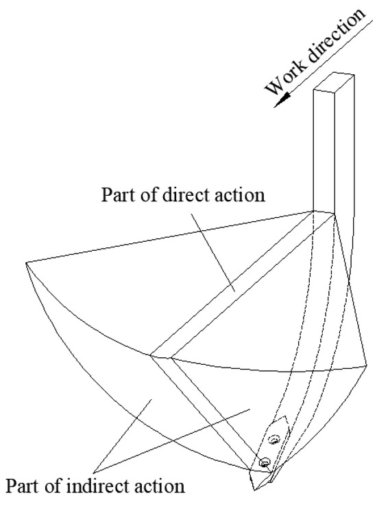
Figure 5.
Diagram of disturbed soil wedge.
The subsoiled furrow contour is as shown in Figure 4. The width of the subsoiled furrow contour can be expressed as the sum of the width of the direct acting part and the width of the indirect acting part on both sides. According to the literature [35], the width of the subsoiled furrow contour can also be expressed as follows
where is the friction angle of the soil to the subsoiler, and 25° is taken, and is the penetration angle of subsoiling shovel, taking 21°.
The width of the indirect acting part b can be expressed as follows
According to Formula (4), = 18 cm and can be solved by Formula (5) to be 31°.
Take an arbitrary radius to make a logarithmic spiral, then the furrow contour can be expressed with Formula (6) [34].
Since the angle between the tangent and radius vector at any point of the logarithmic spiral is complementary to angle , and the furrow contour is orthogonal [34] to the ground surface at point A, can be solved by Formula (7) as 64°.
According to the knowledge of trigonometric functions, obtain the following
Substitute = 18 cm, = 30 cm, = 26°, = 64°, and =3 1° into Formulas (6), (8) and (9) to obtain = 25 cm; =57°. The bottom of the subsoiled furrow contour is a horizontal line equally wide with the subsoiling shovel tip, and its two sides are logarithmic spirals. The equation is as follows:
2.4. Simulation of Deep Loosening Shovel Operation Process
2.4.1. EDEM Simulation Model and Simulation Parameters
Since the soil is a complex heterogeneous material, the reliability of the simulation results depends on the choice of the intrinsic relationship. The soil used in the previous test was mainly composed of clay, silt and sand, and the clay content was 52.7%. According to the soil texture classification standard, it was determined to be clay. In this study, the Hertz-Mindlin (no slip) model was selected as the contact model between particles [36,37,38]. In this model, if two particle units contact, inelastic deformation will occur at the contact point, resulting in normal force and tangential force, which can restore the real state between soil particles and effectively simulate the interaction between the chisel deep loosening shovel and soil particles when moving in soil. At the same time, in order to improve the simulation efficiency, under the premise of ensuring the reliability of the simulation, the particle size and shape of the soil particles are simplified, and the spherical particles with a radius of 4 mm are used as the soil particles.
SolidWorks was used to construct a three-dimensional model (length × width × height) of the soil tank, which was 2000 mm × 400 mm × 350 mm. It was saved in .STL format, imported into EDEM software, the particle factory type as static was added, and the total amount of soil production was set to 470 kg. After the particles were completely generated, compaction was performed. After the virtual soil bin is generated, the three-dimensional model of the chisel deep loosening shovel is imported, as shown in Figure 6. In addition, the relevant parameters of the simulation are set by the team’s previous experiments and references [38,39,40,41], and the specific values are shown in Table 2.

Figure 6.
EDEM subsoiling simulation process.
Table 2.
The required parameters in EDEM.
In order to realize the cutting effect of chisel deep loosening shovel on soil, EDEM is used to add horizontal movement along the y axis to realize the chisel deep loosening shovel operation. The forward speed is set to be 2.5 km/h and the operation depth is 300 mm. The total simulation time is 30 s, the time step is set to be 20% of the Rayleigh step, the data storage interval is 0.01 s, and the simulation grid is 3 times the particle radius. At the same time, in order to speed up the simulation calculation time, a dynamic domain is established in the main working area of the chiseled subsoiler. The dynamic domain will move forward with the chiseled subsoiler at a speed of 2.5 km/h to ensure that the main working area is wrapped at all times. The size of the dynamic domain is set to 500 mm long, 400 mm wide and 800 mm high.
2.4.2. Analysis of Deep Loosening Operation Process
In the EDEM post-processing module, the soil particles are marked in different colors according to different motion speeds. According to the particle velocity from large to small, they are red, dark red, green, dark green, and blue. The particle velocity in the red area is the largest, and the particle velocity in the blue area is the smallest. Therefore, the particle velocity change can be used to reflect the law of the soil disturbance by the chiseled subsoiler.
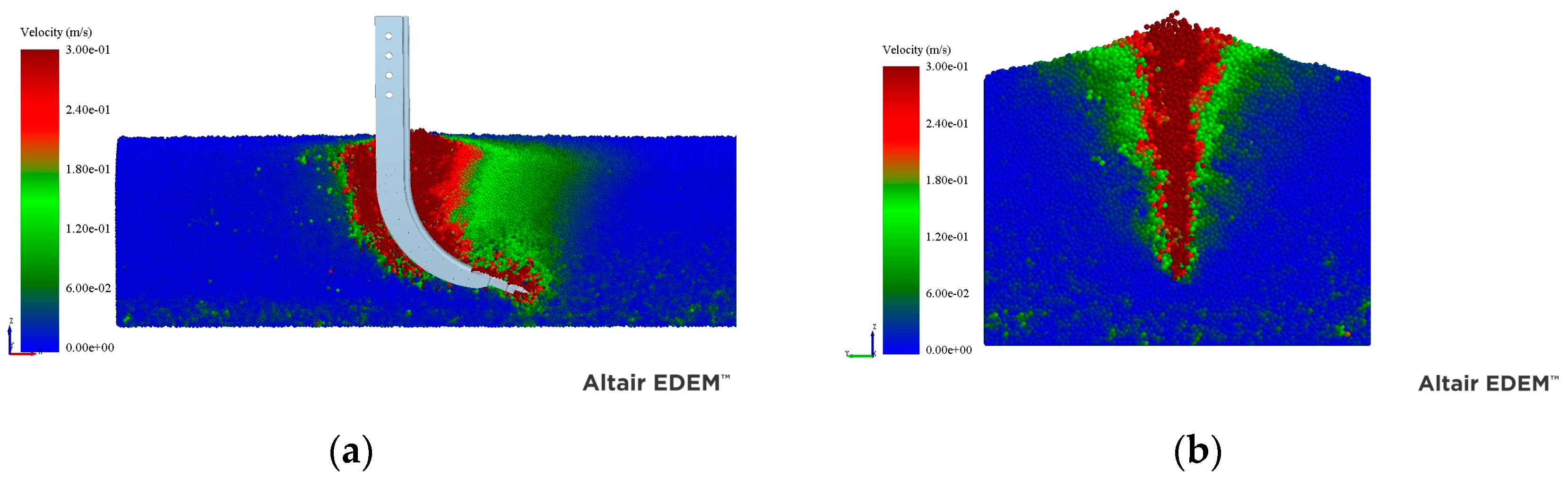
It can be seen from Figure 7 that the shovel tip shears and destroys the soil layer during the operation of the chisel deep loosening shovel. The soil is squeezed by the shovel tip and slides upward along the surface of the shovel handle. The front end of the operation has obvious uplift, and the soil around the shovel is disturbed at the same time. The particle velocity at the contact of the chisel deep loosening shovel is large, and the particle velocity decreases gradually along both sides. The disturbance effect is mainly concentrated in the operation area of the chisel deep loosening shovel and spreads around. Finally, the purpose of destroying the original soil structure and reconstructing the soil state of the soil layer is realized.

Figure 7.
Simulation results of chisel deep loosening shovel. (a) Subsoiling cross-section diagram. (b) Soil disturbance map.
2.5. Subsoiling Test of Pulse-Type Gas Explosion Subsoiler
2.5.1. Test Conditions
The pulse-type gas explosion subsoiler was trial-produced and was tested in a test field in April 2023, as shown in Figure 8.
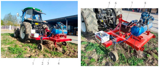
Figure 8.
Experiment of pulse-type gas explosion subsoiler. 1.Limit wheel; 2. air compressor; 3. subsoiling shovel; 4. frame; 5. portable power source; 6. pulse controller; 7. measuring device of field tillage force; and 8. solenoid valve.
The test equipment includes a pulse-type gas explosion subsoiler (self-made), field tillage resistance test system, JPC-2 subsoiling soil cross section mapper, SC900 soil compactness meter, mobile power supply, tape measure, stopwatch, brush, shovel, oven, electronic scale (division value 0.01 g), soil screen, cutting ring, aluminum box, rubber hammer, paring knife, scooper, Vaseline and other tools. Some key experimental equipment is shown in Figure 9. Judging by the experiment, the soil type is viscous soil, the internal friction angle is 25.6°, the soil bulk density is 1.49 g/cm3, the soil density is 1.68 g/cm3, the soil compactness is 128 kPa, and the water content is 13.1%.
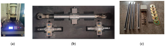
Figure 9.
Some key experimental equipment. (a) Automatic temperature control triaxial apparatus. (b) Field tillage resistance test system. (c) Subsoiling soil cross section mapper.
2.5.2. Experimental Design
To explore the influence law of aerodynamic parameters on tractive resistance and soil disturbance during subsoiling operation, according to the DG/T 026-2019 Subsoiler [42], air pressure, pulse width and pulse interval were taken as influencing factors, and specific tillage resistance and filling power were taken as evaluation indicators. During the test, the adjacent area of the optimal value was determined by the steepest climb test. According to the Box–Behnken principle, a response surface test was designed to obtain the optimal combination of influencing factors and verify it. During the test, the tractive resistance of the machine was measured by the field tillage resistance test system, and the filling power and disturbance area were measured by the subsoiling soil cross section mapper.
Specific tillage resistance refers to the tractive resistance required for subsoiling soil per unit area and is an important indicator to measure the subsoiling efficiency of a subsoil shovel. It takes into account not only the tractive resistance of the subsoiling shovel, but also the soil disturbance area of the subsoiling shovel. The calculation formula is as follows [43]:
where is the specific resistance of subsoiling; is the tractive resistance required by the subsoiling shovel; and is soil disturbance area.
And filling power refers to the percentage of the cross-sectional area formed by the surface line after tillage and the surface line before tillage in the entire working width to the cross-sectional area between the surface line before tillage and the bottom line of the furrow formed by the subsoiling shovel tip. It reflects the variation of the volume and bulk density of the soil structure before and after subsoiling. It is a main evaluation indicator for the soil disturbance effect of subsoiling. The calculation formula is as follows [44]:
where is filling power; is the difference of the surface cross-sectional area after and before tillage; is the cross-sectional area between the surface line before tillage and the bottom line of the actual subsoiling furrow formed by the subsoiling shovel tip.
The steepest climb test was carried out on three factors, namely: air pressure, pulse width and pulse interval, to determine the adjacent area of the optimal value. According to the previous research group research and pre-test results, the value range of air pressure from 0.3 to 0.8 MPa was selected [45]; the value ranges of pulse width and pulse interval from 0.05 to 0.55 s were selected, and specific tillage resistance and filling power were taken as evaluation indicators. The test design and results are shown in Table 3. To eliminate the influence of different dimensions between specific tillage resistance and filling power, the maximum-minimum normalization method was adopted to convert the membership values of specific tillage resistance and filling power. To obtain an ideal combination of test parameters, additional weights were set for specific tillage resistance and filling power. The weight of specific tillage resistance was 0.7 and the weight of filling power was 0.3. The calculation formula is as follows
where is indicator membership value; is indicator value; is the membership value of specific tillage resistance; is the membership value of filling power; is the maximum indicator value: and is a composite score.
Table 3.
Levels of test factors.
To explore the significance of the influence of test factors on evaluation indicators and the influence of interaction of various factors on evaluation indicators and obtain an optimum parameter combination, the three-factor three-level Box–Behnken test was carried out. The levels of the test factors are shown in Table 3.
3. Results and Discussions
3.1. Result Analysis of the Steepest Climb Test
As can be seen from Table 4, when the air pressure gradually increases, the radial stress and tangential stress generated by the air impact on the soil reaches the splitting pressure of the soil, resulting in cracks in the soil and rapid diffusion. Under the dual action of the subsoiling shovel and jet flow, the soil is divided into several soil blocks. At the moment, the soil blocks above the subsoiling shovel are subject to a jet flow, and the cutting force and friction force of the subsoiling shovel to the soil are reduced. Moreover, the uplift of disturbed soil relative to the ground surface increases. When pulse width and pulse interval are large, the dynamic superposition effect cannot be generated on the soil blocks due to a long time between two adjacent pulse intervals. When pulse width and pulse interval decrease gradually, the blowing effect of air flow on soil gradually appears. When pulse width and pulse interval continue to decrease, as the pulse valve has a certain response time, the diaphragm cannot be opened or closed in time, resulting in the weakening of the blowing effect of the resistance reducing air flow on soil. As the composite score was the smallest in the fifth group of tests, the optimal value interval was near the test parameters in the fifth group. The three-factor three-level Box–Behnken test was further carried out by selecting pressure 0.7 MPa, pulse width 0.15 s and pulse interval 0.15 s as the central test points.
Table 4.
Test design scheme and results of the path of the steepest ascent method.
3.2. Results of the Box–Behnken Test
The test results are shown in Table 5. Regression analysis of variance was carried out on the prediction models of the two evaluation indicators, and the results are shown in Table 6. The data show that the p values as the significance levels of the models were both less than 0.01, and the regression model was highly significant. The R2 values as the determination coefficients of the two evaluation indicator models were 0.9782 and 0.9747, respectively, indicating that 97.82% and 97.47% of the changes of the evaluation indicators depended on the selected test factors. The p values of the lack-of-fit of the two evaluation indicators were both greater than 0.1, and the lack-of-fit of the regression model was not significant, indicating that the model has a good fit and can be used for the subsequent optimization analysis of optimal aerodynamic parameters.
Table 5.
Three-factor three-level test results.
Table 6.
Variance analysis of regression model.
The results of variance analysis for specific tillage resistance are shown in Table 6. p < 0.01 for the Y1 model, indicating that this regression model is highly significant, and its absolute coefficient R2 was 0.9782, indicating that this model can fit more than 97% of the test results. Among them, X1, X2, X3 and X1X3 had a highly significant influence on the specific tillage resistance model, and X2X3 had a significant influence on the specific tillage resistance model. The significance of the influence of each variable on specific tillage resistance was in a descending order of X1, X2, X3. The quadratic regression equation of each variable on specific tillage resistance was obtained, as shown in Formula (15), and its lack-of-fit was tested. The lack-of-fit p > 0.1, indicating that the quadratic regression equation has a high degree of fit.
The variance analysis results of filling power are shown in Table 6. p < 0.01 for the Y2 model, indicating that this regression model is highly significant. Its absolute coefficient R2 was 0.9747, indicating that this model can fit more than 97% of the test results. Among them, X2, X1X3 and X2X3 had a highly significant influence on the specific tillage resistance model, and X1, X2 and X3 had a significant influence on the specific tillage resistance model. The significance of the influence of each variable on specific tillage resistance was in a descending order of X2, X3, X1. The quadratic regression equation of each variable on filling power was obtained, as shown in Formula (16), and its lack-of-fit was tested. The lack-of-fit p > 0.1, indicating that the quadratic regression equation has a high degree of fit.
A response surface diagram of the model was generated using the Design-Expert13.0 software, as shown in Figure 10. According to the response surface, the influence laws of interaction factors such as air pressure, pulse width and pulse interval on specific tillage resistance and filling power were analyzed.
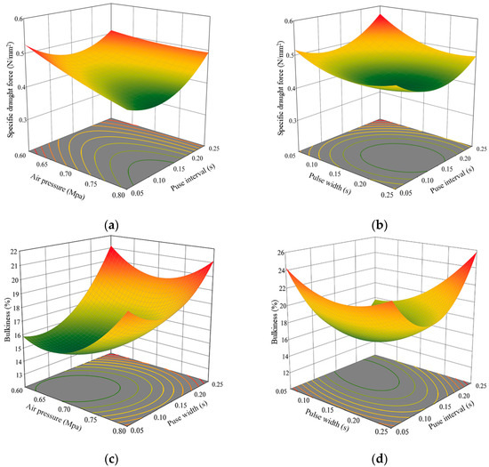
Figure 10.
Interaction effects of factors on subsoiling. (a) Influence of air pressure and pulse interval on the specific draught force. (b) Influence of pulse width and pulse interval on the specific draught force. (c) Influence of air pressure and pulse width on the bulkiness. (d) Influence of pulse width and pulse interval on the bulkiness.
Figure 10a shows the influence laws of air pressure and pulse interval under interaction on specific tillage resistance, respectively, when the pulse width is placed at the middle level. The specific tillage resistance decreased with the increase in air pressure and showed a changing trend of first decreasing and then increasing with the increase in pulse interval. Figure 10b shows the influence laws of pulse width and pulse interval under interaction on specific tillage resistance, respectively, when the air pressure is placed at the middle level. The specific tillage resistance showed a changing trend of first increasing and then decreasing with the increase in pulse width and pulse interval. Figure 10c shows the influence laws of air pressure and pulse width under interaction on filling power, respectively, when the pulse interval is placed at the middle level. The filling power showed a changing trend of first increasing and then decreasing with the increase in air pressure and pulse width. Figure 10d shows the influence laws of pulse width and pulse interval under interaction on filling power, respectively, when the air pressure is placed at the middle level. The filling power showed a changing trend of first increasing and then decreasing with the increase in pulse width and pulse interval.
The reason may be that with the increase in air pressure, the soil wedge and soil aggregate disturbed by subsoiling shovel will be uplifted and migrated by air flow, the subsoiling shovel will have a weaker effect of squeezing and moving soil, and the subsoiling shovel is subjected to less tractive resistance, thus the specific tillage resistance and filling power will gradually decrease. When the air pressure continues to increase, the effect of air flow on the uplifting and migration of disturbed soil continues to strengthen, and the volume of soil begins to increase, thus the specific tillage resistance continues to decrease, and the filling power gradually increases. When the pulse width and pulse interval are large, the blowing volume per unit time is small, which has no obvious effect on the uplifting of soil. Therefore, the resistance reduction effect of gas explosion is not obvious, and the filling power is large. When the pulse width and pulse interval decrease gradually, the blowing volume per unit time reaches the peak value, and the uplifting effect of gas injection on soil gradually appears, while the specific tillage resistance and filling power decrease gradually. When pulse width and pulse interval continue to decrease, as the opening and closing of the solenoid valve have a response time, a signal that the solenoid valve is closed is received before the diaphragm of the valve reaches the maximum opening degree, thus the diaphragm enters the closed state, the injection air cannot be completely released, which weakens the effect of soil uplifting, and the specific tillage resistance and filling power increase gradually.
3.3. Parameter Optimization and Test Verification
In order to obtain the optimum subsoiling operation parameters, with an aim of minimizing specific tillage resistance and filling power, the following conditions are used to select the objective function and various factors:
When the air pressure was 0.8 MPa, the pulse width was 0.17 s and the pulse interval was 0.12 s, the composite score was the lowest. The specific tillage resistance and filling power were 0.4255 N/mm2 and 17.4%, respectively. Test verification was repeated five times under the same test conditions. The specific tillage resistance and filling power obtained from the test are 0.4421 N/mm2 and 18.5%, respectively.
3.4. Comparative Test under Optimized Conditions
A comparative test of subsoiling performance was conducted between the pulse-type gas explosion subsoiler and a continuous gas explosion subsoiler. The running speed of the two machines was set at 2.5 km/h, the working depth was 30 cm, the air pressure of the pulse-type gas explosion subsoiler was 0.8 MPa, the pulse width was 0.17 s, the pulse interval was 0.12 s, and the air pressure of the continuous gas explosion subsoiler was 0.8 MPa. The average value of five tests was used to obtain the specific tillage resistance of the pulse-type gas explosion subsoiler and that of the continuous gas explosion subsoiler were 0.4447 and 0.5065 N/mm2, respectively; the filling power was 18.8% and 21.0%, respectively. The test results show that the tractive resistance and filling power required by the pulse-type gas explosion subsoiler to subsoil soil per unit area are small. It proves that the operation performance of the pulse-type gas explosion subsoiler is superior to that of the continuous gas explosion subsoiler.
4. Conclusions
In this study, according to the requirements of energy saving and drag reduction, based on the principle of pulse gas explosion, a double-end chisel subsoiler composed of subsoiler, air compressor, pulse controller, depth limiting wheel and frame was designed. Through theoretical analysis, the mathematical equations of the structural parameters of the deep loosening shovel and the profile of the deep loosening ditch were established, and the deep loosening operation process was simulated by EDEM software. The law of soil disturbance by chisel deep loosening shovel was analyzed by the change of soil particle velocity.
In order to explore the influence of pulse aerodynamic parameters on the actual subsoiling operation effect, the steepest climbing test and Box–Behnken test were carried out with tillage specific resistance and bulkiness as test indexes. The results showed that the comprehensive evaluation score was the lowest when the air pressure was 0.8 MPa, the pulse width was 0.17 s, and the pulse interval was 0.12 s. At this time, the tillage specific resistance and bulkiness were 0.4421 N/mm2 and 18.5%, respectively. In order to further explore the field operation effect of the design, a comparative test between the pulse gas explosion subsoiler and the continuous gas explosion subsoiler was carried out. The results showed that the specific tillage resistance of the pulse gas explosion subsoiler and the continuous gas explosion subsoiler was 0.4447 and 0.5065 N/mm2, respectively, and the filling power was 18.8% and 21.0%, respectively, which was reduced by 12.2% and 10.5%, respectively. It shows that the pulse gas explosion subsoiler has better working performance and can achieve the purpose of energy saving and drag reduction more effectively.
There are still some shortcomings in this study. The experiments in this paper are carried out under single soil conditions, and the effects of machine operation and subsoiling on crop growth under different soil conditions (different depths and different water contents) are not tested. In addition, the adjustment method of each working parameter of the test device is manual adjustment, which cannot realize the self-adjustment of the working parameters with the working parameters under different soil conditions. Therefore, in future research, it is more important and meaningful to pay more attention to the influence of jet airflow on soil environment and crop growth, and to realize the self-regulation of optimal parameters of the subsoiling device in different environments through intelligent adjustment system, so as to improve the operation effect of the subsoiler.
Author Contributions
Conceptualization, X.X., Q.Y. and H.M.; methodology, J.Q. and X.L.; software, Q.Y. and W.C.; experiment, Q.Y. and X.X.; data curation, Q.Y. and W.C.; writing—original draft, Q.Y. and X.X.; writing—review and editing, Q.Y. and H.M.; visualization, H.P. and P.J.; supervision, H.P.; funding acquisition, H.M. and X.L. All authors have read and agreed to the published version of the manuscript.
Funding
This work was supported by the National Natural Science Foundation of China (grant number: 32060417), and funded by Shihezi University’s strong youth science and innovation backbone talents (grant number: 2022CB002-03) and Shihezi University’s achievements transformation and technology promotion (grant number: CG-ZH202003).
Institutional Review Board Statement
Not applicable.
Data Availability Statement
The data presented in this study are available upon request from the corresponding author.
Acknowledgments
The authors thank the teachers and mentors for their technical support. We would also like to thank our brothers and sisters for their help during the experiment. Finally, we thank editors and anonymous reviewers for providing useful suggestions for improving the quality of papers.
Conflicts of Interest
The authors declare no conflicts of interest.
References
- Ahmad, N.; Fayyaz-Ul-Hassan, F.; Qadir, G. Effect of subsurface soil compaction and improvement measures on soil properties. Int. J. Agric. Biol. 2007, 509–513. Available online: https://xs.typicalgame.com/scholar?hl=en&q=Effect+of+subsurface+soil+compaction+and+improvement+measures+on+soil+properties (accessed on 18 August 2024).
- Shah, A.N.; Tanveer, M.; Shahzad, B.; Yang, G.; Fahad, S.; Ali, S.; Bukhari, M.A.; Tung, S.A.; Hafeez, A.; Souliyanonh, B. Soil compaction effects on soil health and cropproductivity: An overview. Environ. Sci. Pollut. Res. 2017, 24, 10056–10067. [Google Scholar] [CrossRef]
- Edrris, M.K.; Al-Gaadi, K.A.; Hassaballa, A.A.; Tola, E.; Ahmed, K.A.M. Impact of soil compaction on the engineering properties of potato tubers. Int. J. Agric. Biol. Eng. 2020, 13, 163–167. [Google Scholar] [CrossRef]
- Mossadeghi-Björklund, M.; Arvidsson, J.; Keller, T.; Koestel, J.; Lamandé, M.; Larsbo, M.; Jarvis, N. Effects of subsoil compaction on hydraulic properties and preferential flow in a Swedish clay soil. Soil Tillage Res. 2016, 156, 91–98. [Google Scholar] [CrossRef]
- Colombi, T.; Keller, T. Developing strategies to recover crop productivity after soil compaction—A plant eco-physiological perspective. Soil Tillage Res. 2019, 191, 156–161. [Google Scholar] [CrossRef]
- Zheng, K.; McHugh, A.D.; Li, H.; Wang, Q.; Lu, C.; Hu, H.; Liu, W.; Zhang, Z.; Liu, P.; He, J. Design and experiment of anti-vibrating and anti-wrapping rotary components for subsoiler cum rotary tiller. Int. J. Agric. Biol. Eng. 2019, 12, 47–55. [Google Scholar] [CrossRef]
- Zeng, Z.W.; Chen, Y.; Zhang, X.R. Modelling the interaction of a deep tillage tool with heterogeneous soil. Comput. Electron. Agric. 2017, 143, 130–138. [Google Scholar] [CrossRef]
- Song, W.; Jiang, X.; Li, L.; Ren, L.; Tong, J. Increasing the width of disturbance of plough pan with bionic inspired subsoilers. Soil Tillage Res. 2022, 220, 105356. [Google Scholar] [CrossRef]
- Wang, Y.; Li, N.; Ma, Y.; Tong, J.; Pfleging, W.; Sun, J. Field experiments evaluating a biomimetic shark-inspired (BioS) subsoiler for tillage resistance reduction. Soil Tillage Res. 2020, 196, 104432. [Google Scholar] [CrossRef]
- Vanderhasselt, A.; Steinwidder, L.; D’hose, T.; Cornelis, W. Opening up the subsoil: Subsoiling and bio-subsoilers to remediate subsoil compaction in three fodder crop rotations on a sandy loam soil. Soil Tillage Res. 2024, 237, 105956. [Google Scholar] [CrossRef]
- Shahgoli, G.; Fielke, J.; Saunders, C.; Desbiolles, J. Simulation of the dynamic behavior of a tractor-oscillating subsoiler system. Biosyst. Eng. 2010, 106, 147–155. [Google Scholar] [CrossRef]
- Li, B.; Chen, Y.; Chen, J. Modeling of soil–claw interaction using the discrete element method (DEM). Soil Tillage Res. 2016, 158, 177–185. [Google Scholar] [CrossRef]
- Araya, K. Soil failure by introducing sewage sludge under pressure. Trans. ASAE 1985, 28, 397–400. [Google Scholar]
- Zhang, H.; Araya, K.; Kudoh, M.; Zhang, C.; Jia, H.; Liu, F.; Sawai, T.; Yang, S. An explosive subsoiler for the improvement of meadow soil, part 1, thermodynamics. J. Agric. Eng. Res. 2000, 75, 97–105. [Google Scholar] [CrossRef]
- Zuo, S.; Kong, D.; Liu, L.; Dong, X.; Zhao, Y. Experiment on effect of air-pressure subsoiling based on air-pressure cracking theory. Trans. Chin. Soc. Agric. Eng. 2016, 32, 54–61. [Google Scholar] [CrossRef]
- Su, H. Optimization and Design of the Whole Machine and Main Working Parts of Air-Pressure Subsoiler; Inner Mongolia Agricultural University: Hohhot, China, 2021. [Google Scholar]
- Chen, J. Simulation Analysis and Experiment of Soil Loosening Effect by Air Explosion Based on EDEM-Fluent Coupling; Yangzhou University: Yangzhou, China, 2022. [Google Scholar]
- Tu, J.; Zhang, J.; Sui, L.; Zhang, Z. A method of soil subsoiling based on pulse gas explosion. Agric. Technol. 2020, 40, 54–57. [Google Scholar] [CrossRef]
- Zhao, S.; Wang, J.; Chen, J.; Yang, Y.; Tan, H. Design and Experiment of Fitting Curve Subsoiler of Conservation Tillage. Trans. Chin. Soc. Agric. Mach. 2018, 49, 82–92. [Google Scholar]
- Zou, L.; Liu, G.; Yuan, J.; Xin, Z.; Niu, Z. Design and Test of Active Lubrication and Drag Reduction Curved Subsoiler. Trans. Chin. Soc. Agric. Mach. 2022, 53, 34–43. [Google Scholar]
- Wang, Y.; Zhang, D.; Yang, L.; Cui, T.; Li, Y.; Liu, Y. Design and experiment of hydraulically self-excited vibration subsoiler. Trans. Chin. Soc. Agric. Eng. 2018, 34, 40–48. [Google Scholar] [CrossRef]
- Wang, X.; Zhou, H.; Ji, J. Effect of mounting angle on bending subsoiling tool–soil interactions using DEM simulations. Agriculture 2022, 12, 1830. [Google Scholar] [CrossRef]
- Latorre-Biel, J.; Ballesteros, T.; Arana, I.; Alfaro, J.R. Development of an inexpensive rollover energy dissipation device to improve safety provided by ROPS. Biosyst. Eng. 2019, 185, 88–102. [Google Scholar] [CrossRef]
- Villanueva Roldán, P.; Bona, S.; Lostado Lorza, R.; Veiga Suárez, F. Morphological design of a bicycle propulsion component using the hierarchical analysis process (AHP). Appl. Sci. 2023, 13, 7792. [Google Scholar] [CrossRef]
- GB/T24675.2-2009; Conservation Tillage Equipment—Subsoiler. China Standards Press: Beijing, China, 2009. Available online: http://c.gb688.cn/bzgk/gb/showGb?type=online&hcno=C12DBBF43F063D1FD6D49F257BDA769D (accessed on 13 August 2024).
- Ma, S. Force Analysis and Computer Simulation of the Subsoiler in Working State; Henan Agricultural University: Henan, China, 2004. [Google Scholar]
- China Agricultural Science and Technology Press. Handbook of Agricultural Machinery; China Agricultural Science and Technology Press: Beijing, China, 2007; Volume 2. [Google Scholar]
- JB/T 9788-1999; Subsoiler and Share Shaft. China Standards Press: Beijing, China, 1999. Available online: https://www.doc88.com/p-7159547161308.html (accessed on 13 August 2024).
- Liu, J.A.; Wang, X.; Li, H.; He, J.; Wang, Q.; Li, W. Optimization of Structural Parameters of Subsoiler Based on Soil Disturbance and Traction Resistance. Trans. Chin. Soc. Agric. Mach. 2017, 48, 60–67. [Google Scholar]
- Li, B. Agricultural Machinery; China Agricultural Publishing House: Beijing, China, 2003. [Google Scholar]
- GB/T 700-2006; Carbon Structural Steels. China Standards Press: Beijing, China, 2006. Available online: https://www.doc88.com/p-14559459074927.html (accessed on 13 August 2024).
- GB/T 711-2017; Hot-Rolled Quality Carbon Structural Steel Plates Sheets and Strips. China Standards Press: Beijing, China, 2017. Available online: http://c.gb688.cn/bzgk/gb/showGb?type=online&hcno=996FD8117D2B5F49DCF6C27DC6B3157F (accessed on 13 August 2024).
- Shen, C.J.; Jia, S.X.; Zhang, L.X.; Zhou, Y.; Li, F.; Dai, Y.M.; Zhang, J.; Ma, W. Development of caterpillar self-propelled orchard gas explosion subsoiling and fertilizer machine. Trans. Chin. Soc. Agric. Eng. 2019, 35, 1–11. [Google Scholar]
- Ding, Q.; Ge, S.; Ren, J.; Li, Y.; He, R. Characteristics of Subsoiler Traction and Soil Disturbance in Paddy Soil. Trans. Chin. Soc. Agric. Mach. 2017, 48, 47–56. [Google Scholar]
- Dong, Z. Jet Mechanics; Science Press: Beijing, China, 2004. [Google Scholar]
- Hertz, H. On the contact of elastic solids. Journal fur die Reine und Angewandte Mathematik. Crelles J. 1882, 92, 156–171. [Google Scholar]
- Mindlin, R.D. Compliance of elastic bodies in contact. J. Appl. Mech. 1949, 16, 259–268. [Google Scholar] [CrossRef]
- Chen, M.; Liu, X.; Hu, P.; Zhai, X.; Han, Z.; Shi, Y.; Zhu, W.; Wang, D.; He, X.; Shang, S. Study on rotor vibration potato-soil separation device for potato harvester using DEM-MBD coupling simulation. Comput. Electron. Agric. 2024, 218, 108638. [Google Scholar] [CrossRef]
- Dai, F.; Song, X.; Zhao, W.; Zhang, F.; Ma, H.; Ma, M. Simulative Calibration on Contact Parameters of Discrete Elements for Covering Soil on Whole Plastic Film Mulching on Double Ridges. Trans. Chin. Soc. Agric. Mach. 2019, 50, 49–56, 77. [Google Scholar] [CrossRef]
- Niu, Y.; Zhang, J.; Qi, J.; Meng, H.; Peng, H.; Li, J. Design and Test of Soil–Fertilizer Collision Mixing and Mulching Device for Manure Deep Application Machine. Agriculture 2023, 13, 709. [Google Scholar] [CrossRef]
- Li, L.; Chen, J.; Ma, C.; Meng, H.; Qi, J.; Li, Y.; Zhang, P.; Lian, G.; Qi, Z. Study on Soil Throwing Performance and Ditch Depth Stability of Ditching Device in Sandy Orchards in Southern Xinjiang. Appl. Sci. 2021, 11, 12058. [Google Scholar] [CrossRef]
- DG/T 026-2019; Subsoiler. China Standards Press: Beijing, China, 2019. Available online: https://max.book118.com/html/2019/0506/7142001060002024.shtm (accessed on 13 August 2024).
- Li, X.; Li, X.; Wang, S.; Jiang, Z.; You, B.; Wang, X. Experimental study on the influence of air pressure jet angle on pneumatic subsoiling operation. J. Tianjin Univ. Technol. 2024. Available online: https://link.cnki.net/urlid/12.1374.N.20240514.1100.008 (accessed on 18 August 2024).
- Zhao, J.; Wang, A.; Ma, Y.; Li, J.; Hao, J.; Nie, Q.; Long, S.; Yang, Q. Design and test of soil preparation machine combined subsoiling, rotary tillage and soil breaking. Trans. Chin. Soc. Agric. Eng. 2019, 35, 46–54. [Google Scholar] [CrossRef]
- Li, X.; Jiang, Z.; Wang, S.; Li, X.; Liu, Y.; Wang, X. A Study of a Model for Predicting Pneumatic Subsoiling Resistance Based on Machine Learning Techniques. Agronomy 2023, 13, 1079. [Google Scholar] [CrossRef]


Disclaimer/Publisher’s Note: The statements, opinions and data contained in all publications are solely those of the individual author(s) and contributor(s) and not of MDPI and/or the editor(s). MDPI and/or the editor(s) disclaim responsibility for any injury to people or property resulting from any ideas, methods, instructions or products referred to in the content. |
© 2024 by the authors. Licensee MDPI, Basel, Switzerland. This article is an open access article distributed under the terms and conditions of the Creative Commons Attribution (CC BY) license (https://creativecommons.org/licenses/by/4.0/).