Article

Innovative Designs for Cotton Bionic Topping Manipulator

1
College of Mechanical and Electrical Engineering, Xinjiang Agricultural University, Urumqi 830052, China
2
Xinjiang Key Laboratory of Intelligent Agricultural Equipment, Urumqi 830052, China
3
Xinjiang Intelligent Agricultural Machinery Equipment Engineering Technology Research Center, Urumqi 830052, China
4
College of Mechanical and Electrical Engineering, Henan Agricultural University, Zhengzhou 450002, China
5
Key Laboratory of on Site Processing Equipment for Agricultural Products, Ministry of Agriculture and Rural Affairs, Hangzhou 310058, China
6
College of Mechanical and Electrical Engineering, Shihezi University, Shihezi 832000, China
*
Author to whom correspondence should be addressed.
Agriculture 2024, 14(9), 1469; https://doi.org/10.3390/agriculture14091469
Submission received: 30 July 2024 / Revised: 21 August 2024 / Accepted: 26 August 2024 / Published: 28 August 2024
(This article belongs to the Section Agricultural Technology)

Abstract

:
Topping reduces the growing point at the top of cotton plants. This process enables the plant to allocate more energy and nutrients to fruit growth, thereby enhancing both the quantity and quality of the fruit. Current cotton-topping machinery often leads to over-topping, which can affect crop yield and quality. Manual topping is effective in controlling over-topping due to its adherence to agronomic requirements, but it is labor-intensive. This study integrated principles from biology (bionics) to design a manipulator that mimics the action of hand pinching during manual topping. Screening grids of different sizes were designed based on a statistical analysis of the biological parameters of cotton tops to optimize the topping process. A disc cam mechanism was developed to enable the automatic opening and closing of the manipulator. From the results, it was evident that the spring tension must exceed 81.5 N to properly cut the cotton stem near the top. The spacing of the screening grid (40 mm) and the position of the topping manipulator (less than 50 mm) were optimized based on experimental results. Performance testing showed promising results with a 100% topping rate. This study not only identified the challenges with current cotton-topping methods but also proposed a bionics-inspired solution; a bionic manipulator equipped with a screening grid was proposed to achieve high accuracy in cotton topping, which significantly reduced over-topping rates to 6.67%. These findings are crucial for advancing agricultural technology and improving efficiency in cotton cultivation.

1. Introduction

China is the world’s largest producer and consumer of cotton. In 2023, the sown area of cotton in China was about 2,788,100 hectares, with an output of 5,617,900 tons [1]. Cotton topping (removing the top buds of cotton plants) is an important part of cotton production and farmers’ income. Timely topping can inhibit the apical dominance of cotton, providing more nutrients for the reproductive growth of cotton and improving the quantity and quality of cotton bolls [2,3,4,5,6]. Currently, the main methods of cotton topping include artificial topping, mechanical topping, and chemical control [7]. Artificial topping is labor-intensive, low efficiency, high cost, variable in the quality of topping, prone to delays, with limitations as to the area of cotton planting, and not conducive to the development of the cotton industry. Chemical topping is affected by the weather and poor adaptability to the operator’s high technical level requirements, and there is no difference in spraying that will affect the yield and quality of cotton, while multiple sprayings will also cause environmental pollution. Therefore, mechanical cotton topping represents a critical advancement in cotton production practices that urgently addresses these key challenges [8,9,10,11].
Mechanical topping mostly adopts a “one-size-fits-all” approach, and the cut top is generally larger than that of manual topping. Over-topping is the primary issue hindering the application of mechanical topping technology. The cotton-topping machinery execution parts are the core components of topping machinery; researching low-damage cotton topping machinery execution parts is key to solving the over-topping problem [11,12]. Early foreign research on cotton mechanical topping technology dates back to the early to mid-20th century. Griffith, Thomas K. [13] used a rotating disc knife and fixed knife as topping components; Schwarz, Oscar [14] invented the cotton-topping machine and designed a bowed roller cutter as its machinery execution part; Lowrey, Luther A. [15] utilized a collapsible reciprocating cutter as the topping actuator; Bell, Joseph W. [16] and others employed a rapidly rotating horizontal knife as the topping actuator. Currently, the United States, Australia, and other countries use chemical control to eliminate the apical dominance of the cotton plant. In recent years, there has been limited research literature and reports on the mechanized topping of cotton abroad.
Domestic research on cotton-topping machinery execution parts are mainly on the reciprocating cutter, flail knife, drum cutter, and disc knife. The reciprocating cutter, due to its large size, makes it difficult to reproduce the shape that has to be eliminated. The flail knife will be affected by high-speed rotation wind pressure resulting in cotton shaking, affecting cutting accuracy. The drum cutter number is too small, which will lead to a cutting trajectory that is not straight; having too many drum cutters makes it difficult to feed the material properly. Due to the use of unsupported cutting with drum cutters and disc knives, and the large changes in the height of adjacent cotton plants, the overcutting of the cotton plant stems and blades, as well as serious cotton boll excision, occurs, making it difficult to achieve accurate cutting [12,17,18].
Bionic mechanisms can achieve low-damage and low-loss picking and conveying, making them widely applicable in harvesting, straw crushing, and other agricultural engineering fields. For instance, Deng et al. [19] developed a bionic non-destructive apple picker inspired by hand-picking techniques and the use of octopus suction cups to effectively catch apples. Similarly, A. S. H. et al. [20] created a strawberry-harvesting robot designed to address challenges such as low efficiency, low success rates, fruit breakage, difficulty in detecting fruits under unstable lighting, and the high costs associated with robotic harvesting found in previous studies. Furthermore, Gao et al. [21] developed both a vacuum end-effector and a rotary end-effector specifically for harvesting cherry tomatoes. In addition, Li et al. [22] investigated a human hand-based, rope-driven adaptive end-effector for non-destructive pear picking. This end-effector features three fingers, each consisting of two knuckles, and the experimental results indicate that it provides stable grasping while adapting to the various sizes and shapes of pear fruits. Complementing these innovations, Pi et al. [23] designed a three-fingered flexible bionic robot for apple grasping. Compared to other soft grippers, this bionic flexible gripper offers advantages such as lightweight construction, excellent cushioning performance, low driving air pressure, and strong gripping force. Lastly, Zhao et al. [24] conducted a coupled bionic design of the structural and kinematic elements of locust mouthparts, leading to the development of a bionic straw returner that significantly reduces cutting power consumption and improves the crushing length pass rate compared to traditional straw returners. In view of the above analysis, this paper on the study of the physical characteristics (an important research direction in the intersection of biology and physics) of cotton tops (top buds), combined with the principles of bionics, designed a cotton bionic topping manipulator (an actuator), to reduce cotton mechanical topping damage and provide a basic theory and experimental data.

2. Materials and Methods

2.1. Physical Characteristics of Cotton Plants

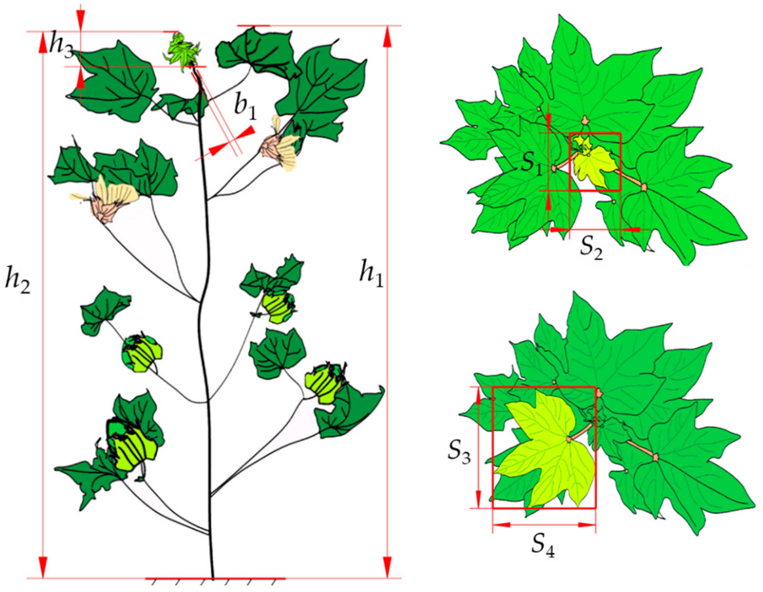
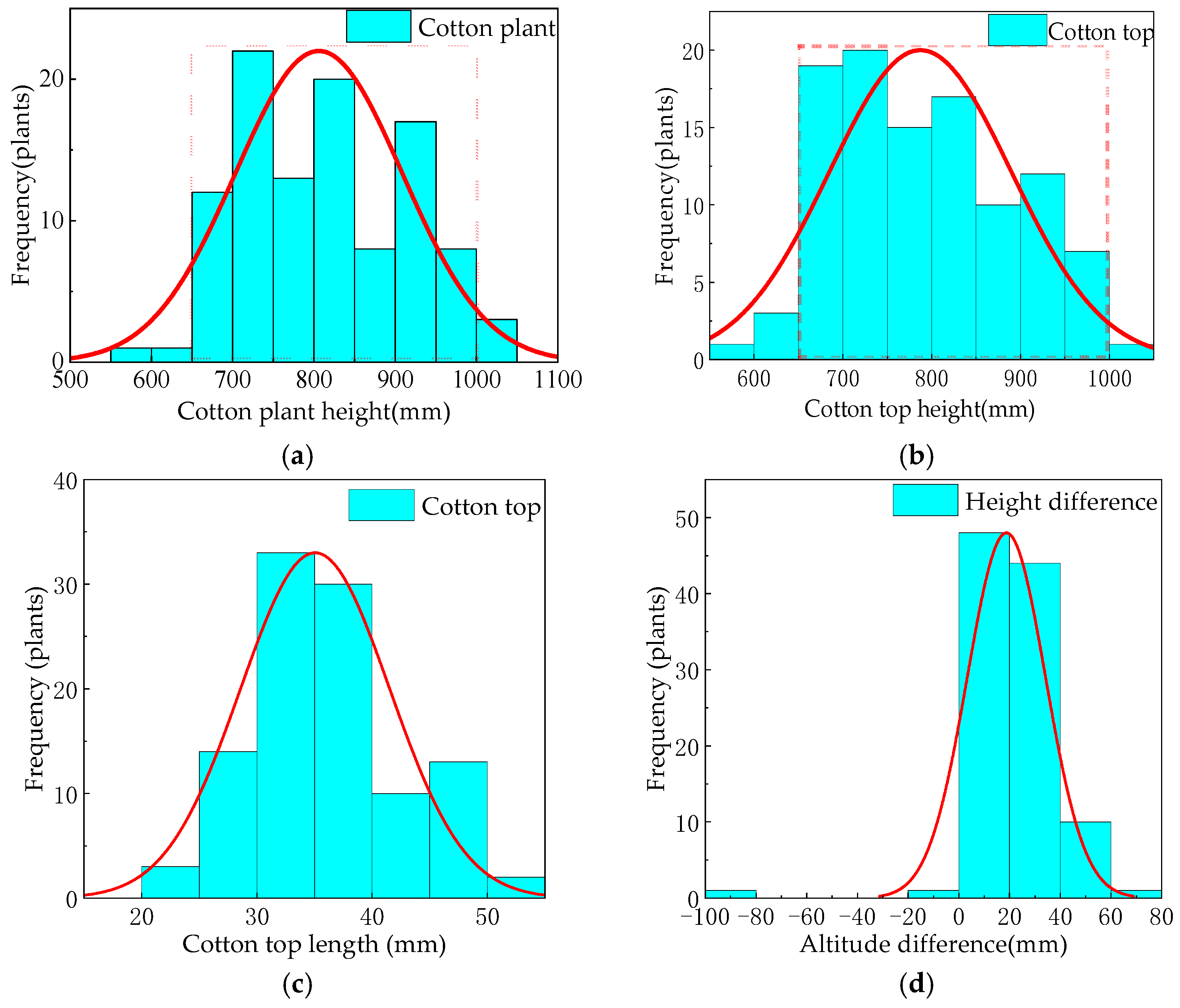
2.1.1. Measurement of Cotton Plant Growth Parameters

On 10 July 2022, cotton plant growth parameters were measured in a field located in Dalet Town, Bole City, Bortala Mongol Autonomous Prefecture, Xinjiang, China. Machine-picked cotton in optimal growth conditions at the topping stage was chosen for evaluation. The variety was Xinluzao (Selected and bred by Institute of Agricultural Science, Agricultural Division No. 7, Xinjiang Production and Construction Corps, Ürümqi, China) cotton cultivars.
Measuring Methods: During the cotton-topping period, the plum blossom layout method is used for field sampling. In this approach, sampling points are arranged in a pattern resembling a plum blossom. Each point is positioned at the intersection of the “petals” of the plum blossom design, ensuring an even distribution of sampling points across the field. This involves selecting five points within the center of the plum petals, with each row consisting of 21 cotton plants, totaling 105 plants, and the numbering of the selected cotton plants using paper labels. Measurements included using a tape measure (Manufacturer: Deli Tools Co., Jinhua, China; Range: 0~5000 mm, Accuracy: 1 mm) and two steel plate rulers (Manufacturer: Deli Tools Co., China: steel plate ruler 1, Range: 0~1500 mm, Accuracy: 1 mm; steel plate ruler 2, Range: 0~500 mm, Accuracy: 1 mm) to measure the height of the cotton plant (h1), the height of the cotton top (h2), and the length of the cotton top (h3). A vernier caliper (Manufacturer: Deli Tools Co., China; Range: 0~150 mm, Accuracy: 0.02 mm) was used to measure the cross-sectional size (b1) of the cotton stem just below the top. For top-down views, coordinate paper (Brand: Tianshun; Accuracy: 1 mm) was used to measure the rectangular area encompassing the cotton top and adjacent blades. This provided dimensions for both the cotton top (S1, S2) and the adjacent blade (S3, S4). The data obtained were analyzed using Origin software (Development Company: OriginLab corporation, Northampton, MA, USA; version 2021) for descriptive statistics [25,26]. The schematic representation of measurement locations is depicted in Figure 1.
The distribution statistics for cotton plant height, top height, top length, and the difference between plant and top height are depicted in Figure 2. At the topping stage, these metrics exhibited an approximately normal distribution in the sample. Cotton plant heights and top heights ranged from 650 mm to 1000 mm (highlighted by the red dashed box in the figure), with cotton plants having a top height less than 1000 mm constituting 99.05% of the sample. Top lengths were predominantly within 50 mm (inclusive of 50 mm). Moreover, approximately 98.10% of cotton plants in the sample had heights exceeding their top heights, with an average difference of less than 20 mm. This suggests that the proximity of blades near the cotton top makes them susceptible to damage during mechanical topping, potentially leading to over-topping.
Figure 3 illustrates the distribution of cotton top sizes (S1, S2) and sizes of blades adjacent to the top (S3, S4) within the sample. The analysis reveals distinct distribution patterns for these parameters. For cotton top sizes (S1, S2), the maximum observed value was 75 mm, with an average of approximately 42.2 mm. Tops with sizes (S1, S2) equal to or less than 65 mm accounted for 95.24% of the sample. Regarding the sizes of blades adjacent to the top (S3, S4), the maximum observed value was 125 mm, averaging around 83.4 mm. Blades with sizes (S3, S4) greater than 65 mm constituted 90.95% of the sample.
The difference in the length of the outer rectangle contour sides of the cotton top and the adjacent blade was monitored, as depicted in Figure 4. The maximum difference in the length of the outer rectangle contour sides of the cotton top dimensions was 25 mm, with differences not greater than 15 mm accounting for 97.14% of the sample size. For the adjacent blades, the maximum difference in length next to the top was 32 mm, and 96.19% of the samples had a difference not more than 20 mm. These findings suggest that the outer rectangle contour of the cotton top and surrounding blades approximates a square shape, with relatively minor disparities in length between the sides of the cotton top (S1, S2) and the adjacent blades (S3, S4). This allows the size of the top to be represented by Max (S1, S2), and the size of the adjacent blades by Max (S3, S4).
The cross-sectional dimensions of cotton stalks under the top were measured at intervals of 0 mm, 10 mm, 20 mm, and 30 mm downward from the starting position of the top hitting. The measurements were taken in two perpendicular directions, as illustrated in Figure 5. These directions were designated as positions 1 (long side) and 1 (short side), positions 2 (long side) and 2 (short side), positions 3 (long side) and 3 (short side), and positions 4 (long side) and 4 (short side). The absolute differences between the measurements in these positions were termed as the long- and short-side differences.
Figure 6 presents the measurement results and subsequent statistical calculations yielding average values of 5.2 mm, 4.99 mm, 6.05 mm, and 6.77 mm for the long sides of positions 1, 2, 3, and 4, respectively. Similarly, average values of 4.54 mm, 4.45 mm, 5.30 mm, and 5.81 mm were obtained for the short sides of positions 1, 2, 3, and 4, respectively. The mean differences between the long and short sides at positions 1, 2, 3, and 4 were calculated as 0.66 mm, 0.54 mm, 0.75 mm, and 0.96 mm, respectively, indicating that the differences were generally less than 1 mm. Position 2 exhibited the smallest difference between the long and short sides, suggesting that its cross-section was nearly square. Singular values were observed due to the fixed measurement position near the petiole node. Excluding this position, the cross-sections of the stalks could be considered square.
To ensure consistent test results, the long side of the stalk cross-section was selected to represent the stalk diameter. During measurements, it was noted that stalks closer to the top appeared green, while those at a greater distance displayed a purplish-red coloration.

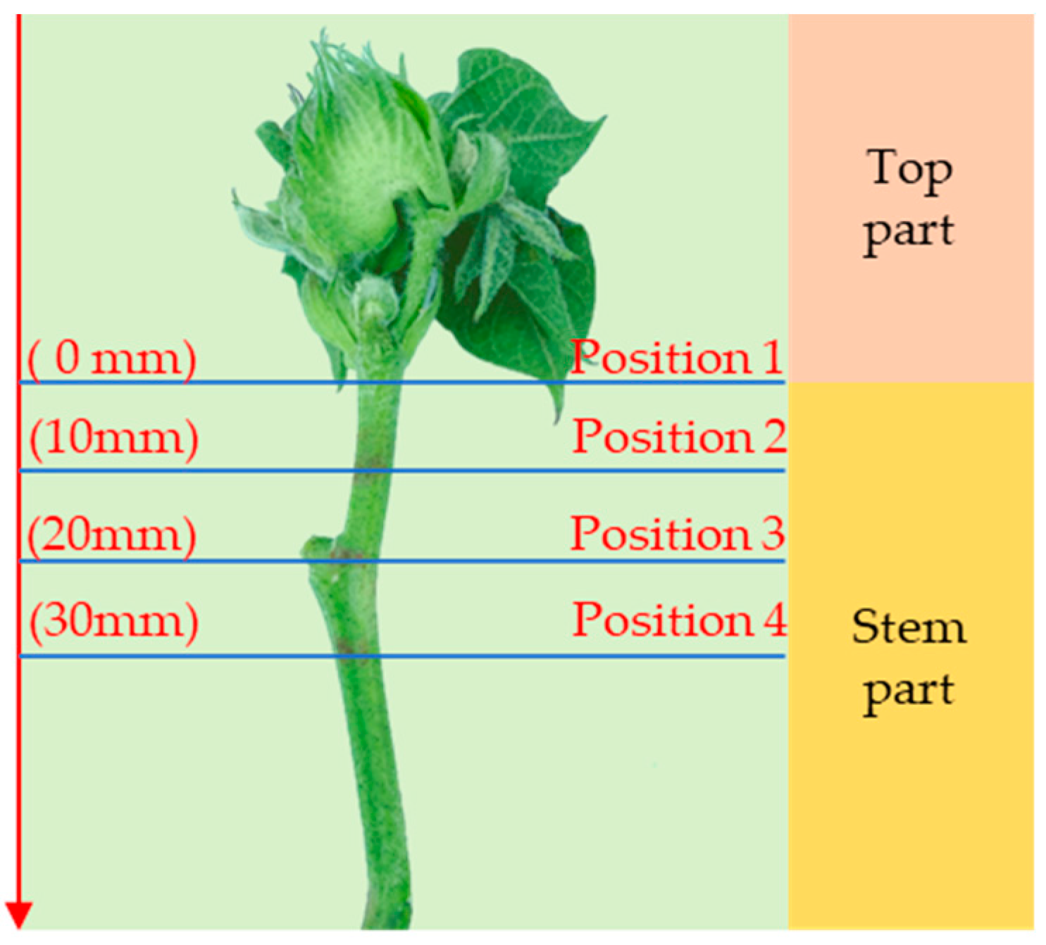
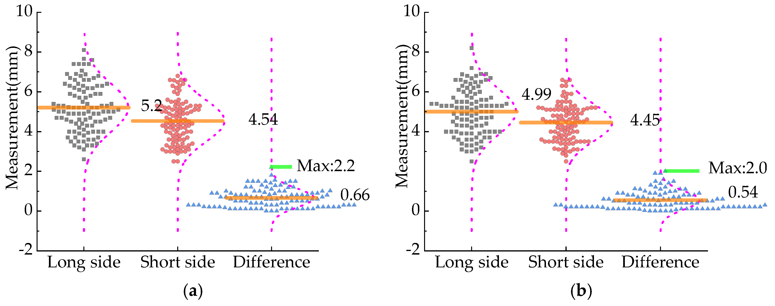
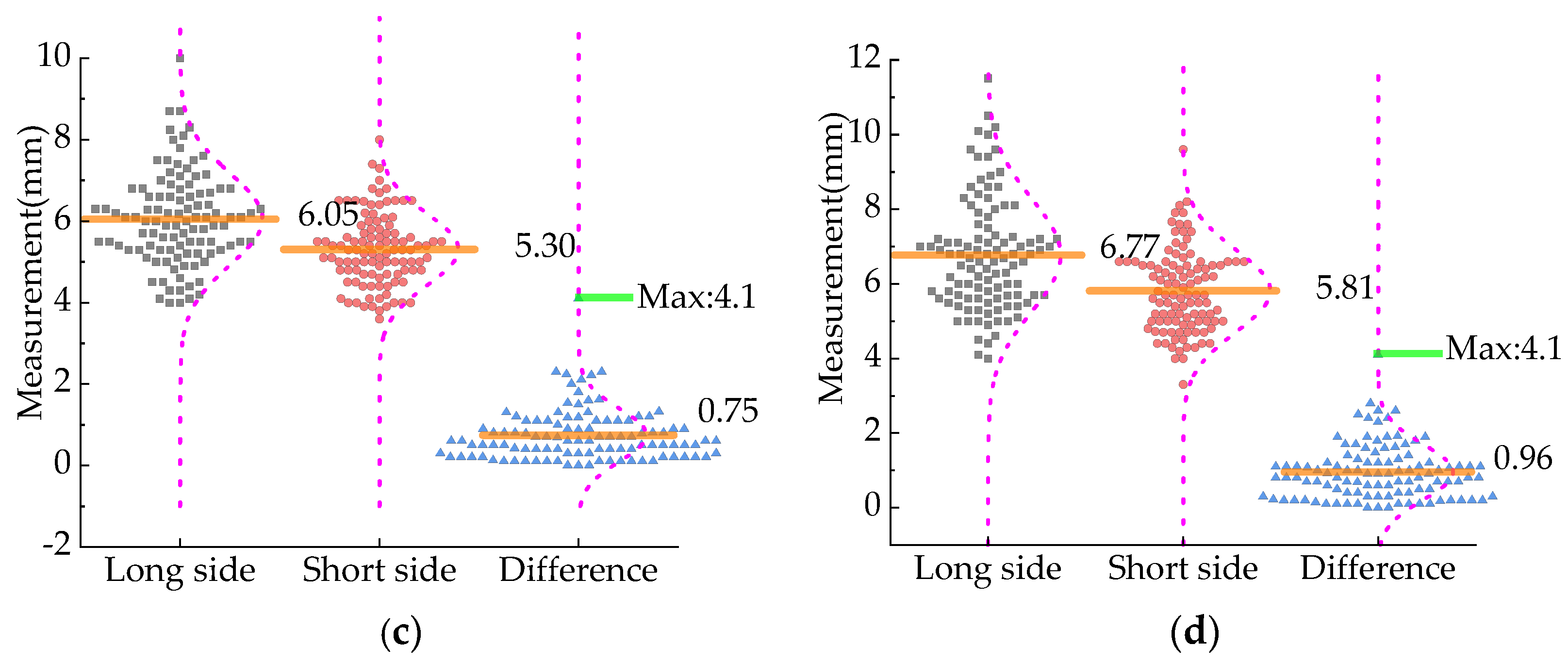
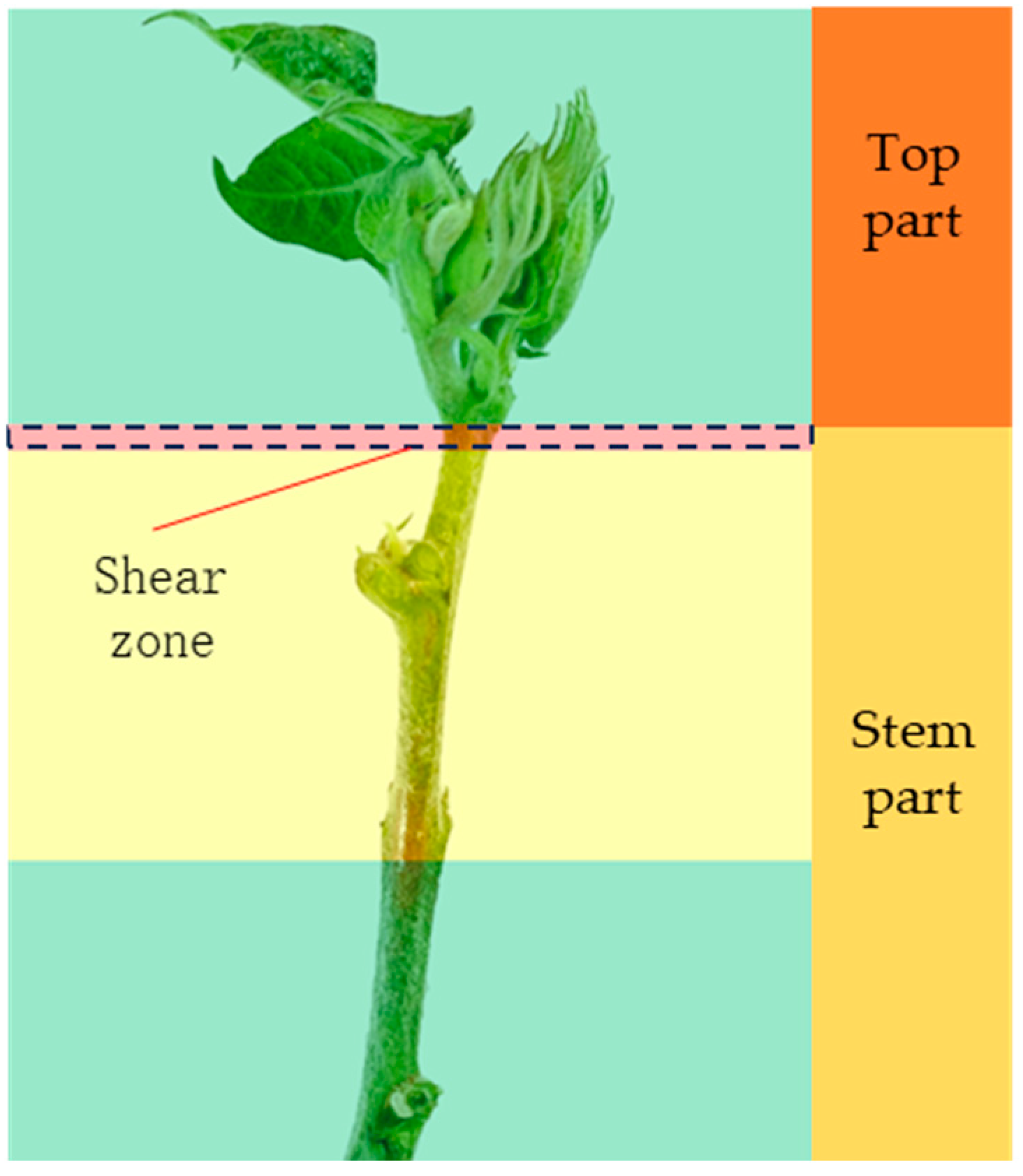
2.1.2. Determination of Mechanical Properties of Cotton Stalk Shearing at the Top of Cotton

The introduction of this paper highlights the challenges with existing topping execution parts, noting their limitations in achieving precise cutting and their tendency to cause over-topping. In manual topping, the top is grasped between the thumb and forefinger, and then the top of the thumb shears off the top, ensuring reliable and precise action without the occurrence of over-topping. Consequently, there is a need to conduct tests to determine the shearing force required at the stem’s top in cotton [25,27].
The test methods involved using vernier calipers (Manufacturer: Deli Tools Co., Jinhua, China; Range: 0~150 mm, Accuracy: 0.02 mm) to measure the cross-sectional dimensions of the stalks at their tops. The mechanical properties of these stalks were evaluated using an electronic universal testing machine (Manufacturer: Shenzhen Reger Instrument Co., Shenzhen, China; Machine Model: Rigel RGM-4002 intelligent electronic universal testing machine; Range: 0~2 kN, Precision: ±0.5% of the value) set to a loading speed of 1.0 mm/s, with limit stops employed to restrict the stroke and prevent machine overload. The testing procedure included securing a fixture and a homemade shear blade (thickness of 2.8 mm and unopened edges were also utilized) on the test bench of the universal testing machine. This setup ensured that the blade sheared at the closest position to the top culm, as indicated by the dotted line box in Figure 7. Test data were subsequently collected, read, and stored using a computer [25,28].
The shear test method for cotton tops and the shear load–displacement curve of the stem at the cotton top are illustrated in Figure 8, where displacement is plotted on the horizontal axis and shear load on the vertical axis. The load depicted in the figure changes gradually in stages before reaching its peak. In the early stage (0–1 mm displacement), there was minimal variation in shear load due to the elastic deformation of the stalk at the top. However, as tangential pressure on the stem at the top increases, the load sharply rises (displacement of 1 mm to 2 mm). After peaking, the load gradually decreases in stages. This occurs because the cotton top experiences a gradual displacement under the existing external load on the stalk. As displacement increases, the load induces deformation within the internal tissue of the stalk. Until the displacement exceeds the recoverable deformation capacity of the stalk, the tissue undergoes shear once more, leading to its destruction and ultimately causing the complete fracture of the stalk. The mean long-side dimension of the stem at the top of the specimen was 3.49 mm, with a maximum dimension of 4.78 mm. The mean shear force measured was 15.94 N, with a maximum shear force of 30.56 N. An analysis has shown that the magnitude of the shear force correlates with the maximum longitudinal dimension of the stalk at its apex. Based on the method used, shear force tests were conducted on the main stem below the top of the same cotton plant [25,28]. The results indicated that stalks located farther down from the top exhibited higher shear forces in the main stem below them. Position 4 stalks necessitate an average shear force of 29.62 N, with a peak force reaching up to 80.79 N.

2.2. Design of Bionic Topping Manipulator for Cotton

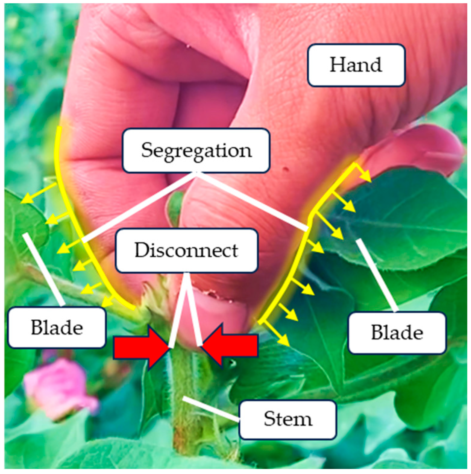
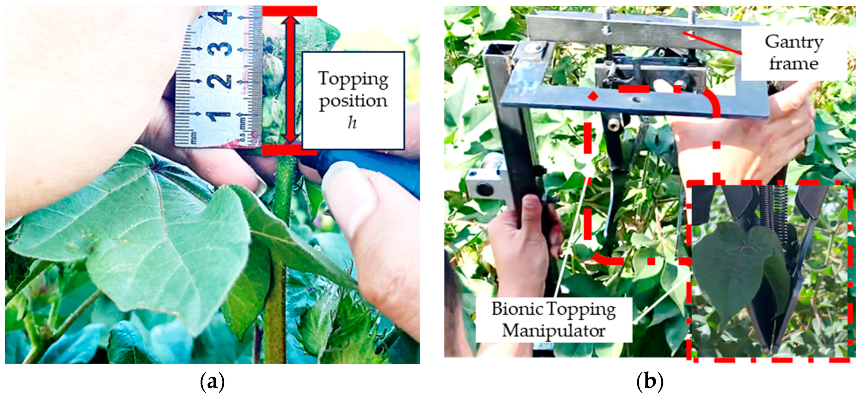
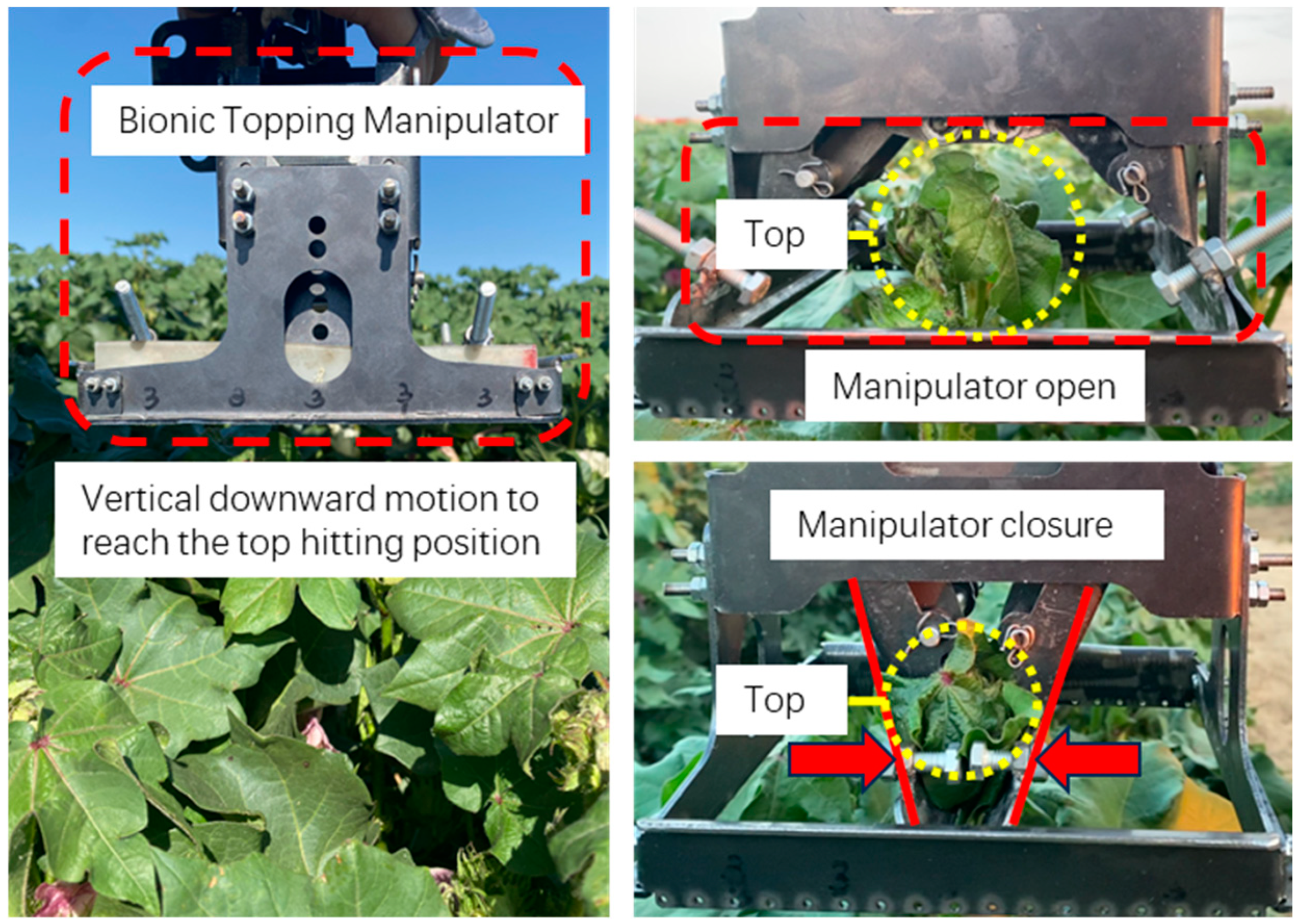
2.2.1. Artificial Topping Method

In the artificial topping process, during the hand’s descent to grasp the cotton top, it skillfully maneuvers around the blade, ensuring the fingers separate the top from the plant (as depicted in Figure 9). This method is dependable in preventing over-topping. The design of a biomimetic topping manipulator should incorporate the following functionalities: 1. Separate cotton tops from blades next to tops (As shown by the yellow arrow in Figure 9). 2. Precise removal of topping to mimic human hands (As shown by the red arrow in Figure 9) [29,30,31].

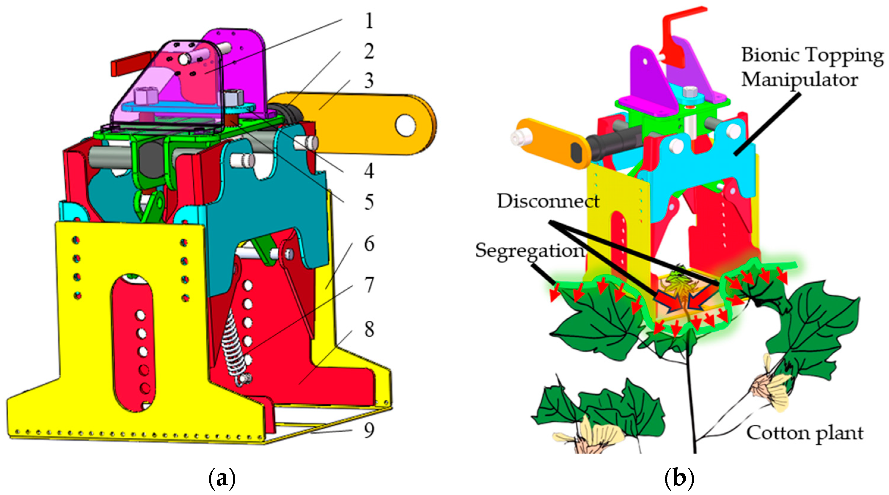
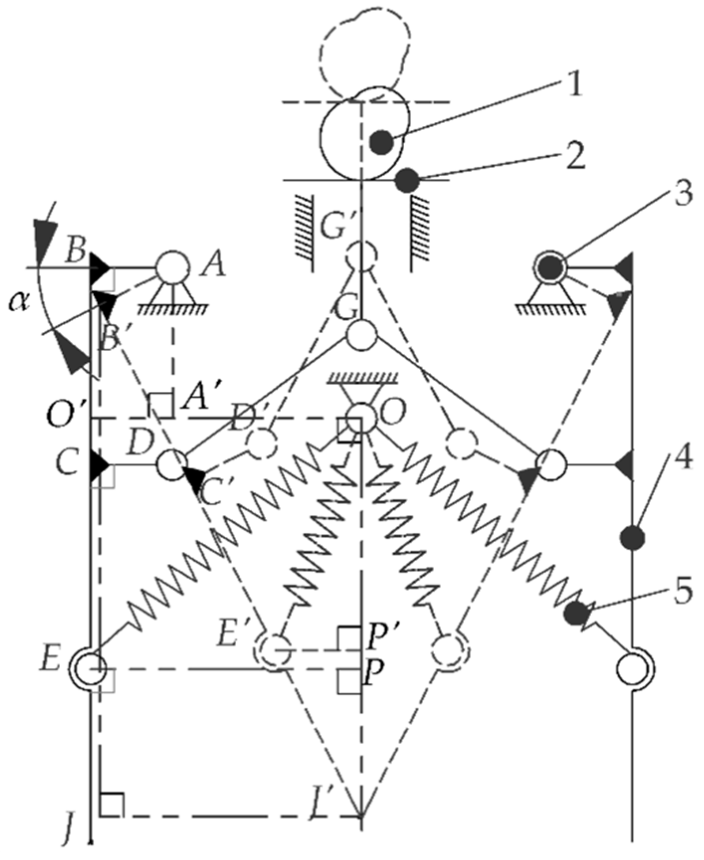
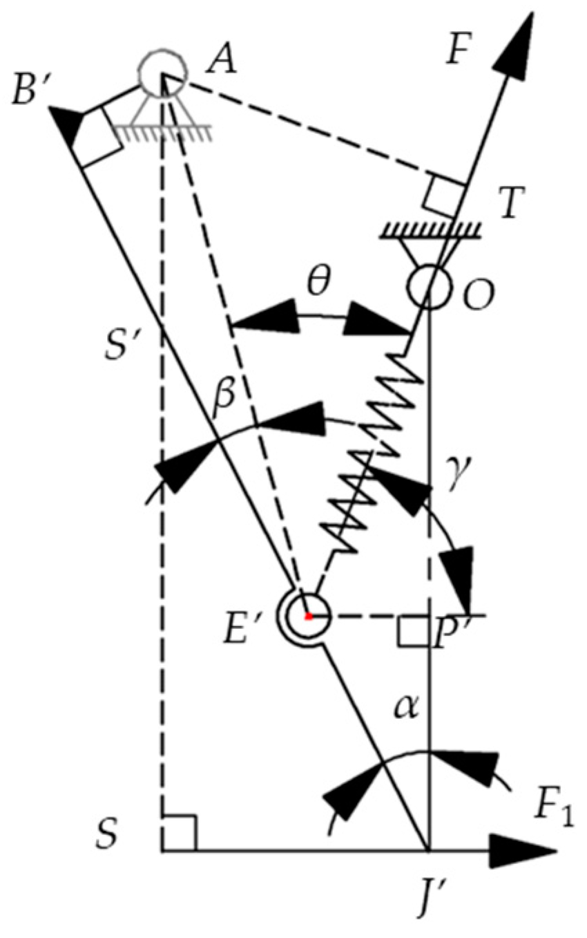
2.2.2. Working Principle of Bionic Topping Manipulator

The bionic topping manipulator was designed based on the manual topping method, integrating bionics principles. It includes components such as a cam, fixed mounting shaft, connecting arm, flat bottom follower, push rod, cover shell, tension spring, pinch finger, and screening grid, as illustrated in Figure 10a. The screening grid separates the top from the adjacent blade, while the pinch finger mimics human fingers to cut the top. During operation, as depicted in Figure 10b, the cam rotates to the far rest position. The flat bottom follower, in conjunction with the cam, pushes the push rod downward vertically, opening the pinch finger. As the top passes through the screening grid and between the fingers, the cam moves to the near rest position. The flat bottom follower and push rod reset, causing the pinch finger to swiftly close under spring force, thereby cutting the cotton top [30].

2.2.3. Design of Key Components

A sketch of the bionic topping manipulator is depicted in Figure 11. The manipulator is symmetrically arranged, with its open state indicated by solid lines, where the two pinch fingers are parallel and spaced 150 mm apart. The dotted line indicates the state in which the pinch finger is closed by rotating the pinch finger around point A at an angle α (29°). A long and two short dashed lines indicates the extension of a point along a horizontal or vertical direction. One end of the tension spring is fixed at point O. Point E(E′) is the other fixed point of the spring. Key dimensions include lOO′ at 75 mm, lOA′ at 40 mm, lBO′ at 10 mm, lAB at 35 mm, and the pinch finger length lBJ at 142 mm.
(1)
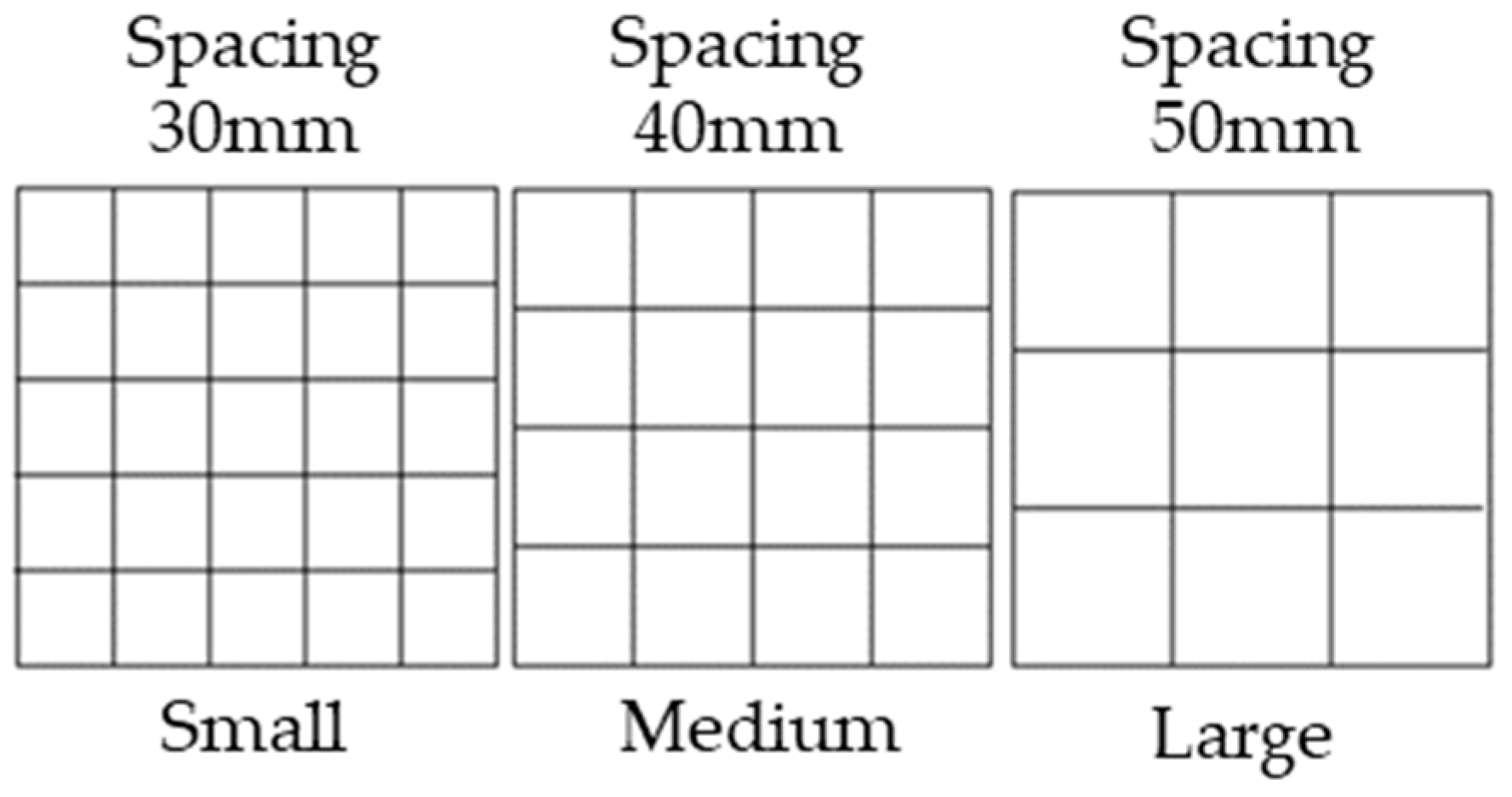
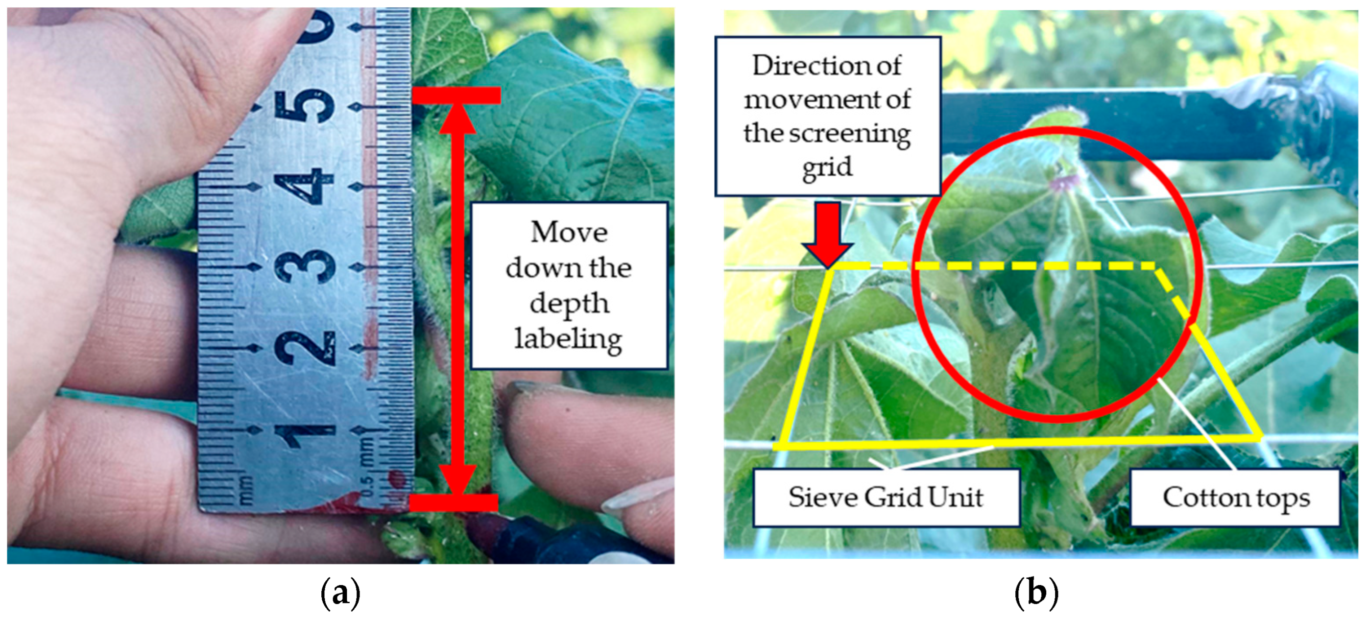
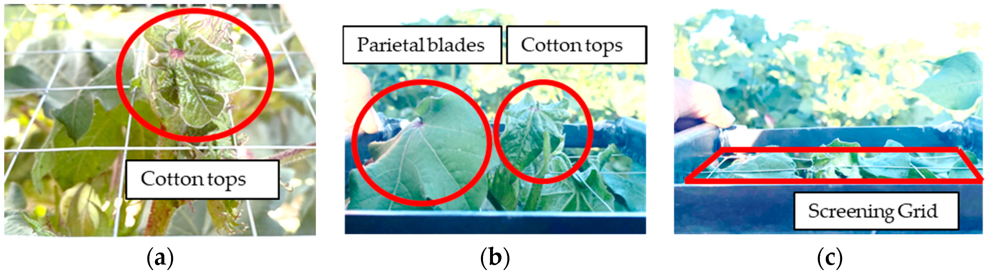
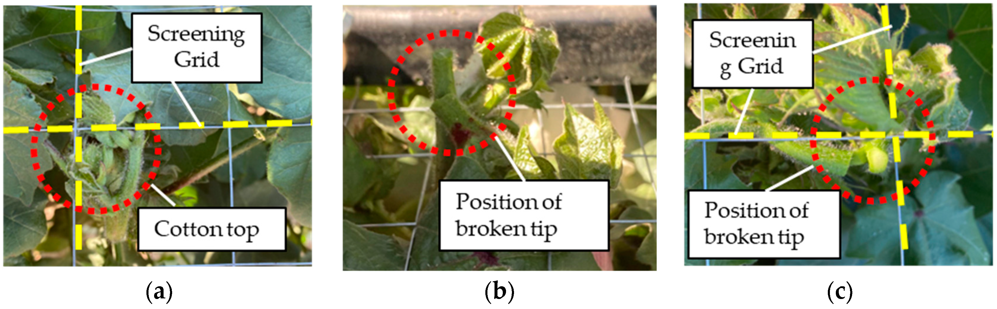
Design of sieving grid:
Cotton plants often have dense branches and blades around their tops, making it challenging to mechanically top them without damaging the surrounding foliage (over-topping). Therefore, the bionic topping manipulator needs a mechanism to separate the cotton top from the neighboring blades. The cotton top primarily consists of a bud and a blade. The bud is small, tightly connected to and supported by the stalk, while the blade is softer and smaller, prone to deformation upon impact. The blades adjacent to the top are larger with softer petioles, making them less likely to pass through a grid during separation.
Taking advantage of these differences, a screening grid was used to move from the top of the cotton plant downward, effectively separating the surrounding blades and exposing the cotton top through the grid. The measuring procedure was based on techniques from previous studies, where the sizes of the cotton tops and adjacent blades are as follows: The average dimensions of the cotton top (S1, S2) are around 42.2 mm, with 95.24% of samples having sizes not greater than 65 mm. The adjacent blade (S3, S4) averages about 83.4 mm, with 90.95% of samples having sizes greater than 65 mm. Due to the existence of a certain degree of flexibility of the top and the blade, three different specifications of the screening grid (small, medium, and large) were designed, as shown in Figure 12.
(2)
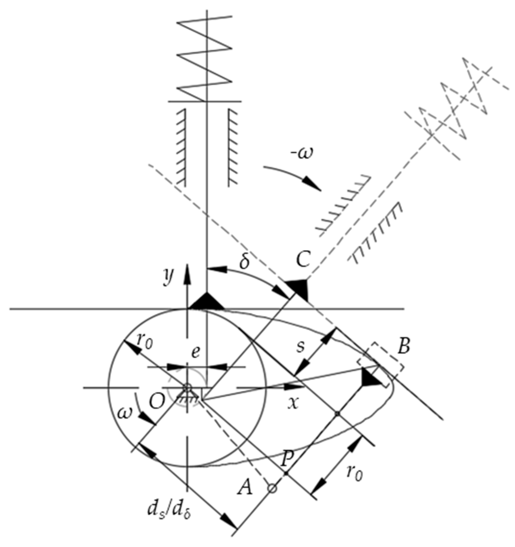
Design of cam mechanism
To replicate the manual topping action, the bionic topping manipulator was designed to keep its pinch fingers open during vertical downward movement, closing swiftly upon reaching the topping position. The cam mechanism, known for its simple structure and compact size, utilizes a flat-bottomed follower disc cam to achieve high transmission efficiency. This configuration facilitates the formation of a wedge-shaped oil film between the cam profile and the flat-bottomed follower, ideal for high-speed transmission mechanisms. Employing the flat-bottomed follower disc cam type enables automated control of the bionic topping manipulator’s opening and closing actions [32,33]. Figure 13 offers a structural diagram of the cam mechanism.
1) Determination of pressure angle
The pressure angle is the direction normal to the cam profile line at the contact point (direction of positive pressure on the flat-bottomed follower), forming an acute angle with the velocity direction of the flat-bottomed follower. In the flat-bottomed follower disc-type cam mechanism, it is observed that when the flat-bottomed follower is perpendicular to the push rod, the direction normal to the contact point between the cam and the flat-bottomed follower aligns parallel to the motion direction of the flat-bottomed follower. This results in a pressure angle α of 0° (assuming negligible friction). Thus, the cam mechanism meets the requirement that the pressure angle α be less than [α] ([α] is 30°).
2) Determination of base circle radius
Applying the method of reverse rotation reveals that a rotation of δ angle by the cam results in a corresponding displacement s of the push rod. At point B, where the cam profile curve intersects the flat bottom follower, denoted as point B, the curvature of the cam is ρB. Thus, the theoretical profile equation for point B is given by Equation (1).
{ x = ( r 0 + s ) sin δ + l o p cos δ y = ( r 0 + s ) cos δ l o p sin δ
The center of curvature of contact point B is known to be point A, while point P serves as the instantaneous center of the cam and pushrod. Using the lower pair method, the four-bar mechanism OABC was established, where V denotes the speed of the pushrod movement. In the initial mechanical position of the cam (δ = 0), ensuring reliable movement of the flat-bottomed follower disc cam required a careful design of the base circle radius and the width of the flat bottom. Equation (2) was derived using the principle of acceleration imaging, assuming the cam rotates at a uniform speed.
l A P = d 2 s d δ 2
In Figure 13, the radius of curvature of the cam at point B can be expressed by Equation (3).
ρ B = d 2 s d δ 2 + r 0 + s ρ B min
where s represents the displacement of the flat-bottomed follower (mm), δ denotes the cam angle in degrees (°), and r0 is the radius of the base circle (mm).
A convex profile curve can be achieved as long as ρB is more than 0 mm. However, the curvature radius is often too small and prone to wear. Therefore, it is typically specified that the minimum radius, ρBmin, must be a specific value to ensure that everywhere on the contour curve, ρB is not less than ρBmin. Considering the operational principle of the cam in the bionic topping manipulator, special trajectory requirements are not imposed to prevent excessive wear of cams. It is advisable to set a ρBmin greater than [ρ] ([ρ], which ranges from 1 mm to 5 mm). Consequently, Equation (3) can be expressed by Equation (4).
ρ B min = r 0 + ( d 2 s d δ 2 + s ) [ ρ ]
To prevent cam overcutting and follower motion distortion, the radius of the designed base circle must exceed the radius of curvature of points on the cam profile curve, as required by Equation (5).
{ r 0 ρ B min ( s + l A P ) min ( s + l A P ) 0 ρ B min [ ρ ]
Since the base circle radius (r0) remains constant, the minimum radius of curvature (ρBmin) of the convex contour line occurs at the minimum of (s and lAP). From a mathematical perspective, the minimum value of the sum of s and lAP is 0 mm. This allows a r0 between to 1~5 mm). Given the compact structure of the bionic topping manipulator, the cam and shaft can be integrated into a single unit. The base circle radius of the cam’s working contour should slightly exceed the shaft’s radius, which is 4 mm in diameter. Setting the cam’s base circle radius (r0) at 6 mm ensures compliance with the requirement that the flat-bottomed follower maintains a radius of curvature (ρ) greater than 0.
3) Determination of the size of the flat bottom follower
To accommodate the required working margin of the flat-bottomed follower, the length of the flat bottom was calculated using Equation (6).
{ l O P = d s d δ e V m = ( d s d δ ) max 2 l = 2 | l O P | max + ( 5 ~ 7 ) mm
Among these parameters, the eccentricity distance (e) was 11.5 mm. A lower (Vm) can decrease the cam’s base circle radius, thereby compacting the cam mechanism. For (Vm = 2), the length (l) of the flat-bottomed follower should exceed 32 mm for ease of assembly. Considering all factors, the optimal length (l) for the flat-bottomed follower was determined to be 43 mm.
(3)
Design of the tension spring
1) Calculation of spring force
It was evident through studying the physical characteristics of the cotton plant that the size of the main stem stalk increased with the distance from the top, necessitating greater shear force. The average shear force at the top of the cotton was 15.94 N, with a maximum of 30.56 N. The appropriate tension spring force ensures that the bionic topping manipulator maintains sufficient shearing force at the topping position, preventing excessive topping further down from the cotton’s top. To ensure the reliability of the topping operation, a safety factor of 1.5 was employed based on a maximum shear force of 30.56 N. The shear force at point J as the bionic topping manipulator was closed amounted to 45 N. It was therefore essential to calculate the required tensile spring force. This calculation was based on the positional relationship depicted in Figure 11. It further led to the simplified schematic diagram shown in Figure 14, illustrating the relationship between the tensile spring force and shear force. In this diagram, the closure of the bionic topping manipulator is represented by a solid line. Additionally, the line segment (lAT) is perpendicular to the direction of force (F), (lAS) is perpendicular to the direction of force (F1), and (lAS) intersects (lBJ) at point (S′).
This relationship was derived from Figure 14, utilizing the principle of leverage (Equation (7)).
l A S × F 1 = l A T × F
From Equation (7), determining the tension force (F) of the tension spring requires calculating the magnitudes of (lAS) and (lAT). (lAS) can be computed using Equation (8).
l A S = l S S + l A S
The combination of trigonometric relations in triangles Rt△ASB′, Rt△EAT, and Rt△SSJ yields the following.
{ l S S = l S J tan ( 90 ° α ) l A S = l A B 2 + l B S 2 l B S = l B J l S J l S J l S J = cos ( 90 ° α )
under the given conditions (lSJ = 40) mm, (lBE = 120) mm, and the unilateral gripping force (F1) of the bionic roofing manipulator was 22.5 N. Substituting the results from Equation (9) into Equation (8), (lAS) was calculated to be 141.18 mm. In triangles Rt△EAT, Rt△EAB′, and Rt△OEP′, trigonometric functions yielded the following relationships.
{ l A T l A E = sin θ l A B l B E = tan β l E P l O P = tan ( 90 ° γ )
Based on the positional relationship in Figure 14 and incorporating known conditions into Equation (10), (lAT) was determined to be 39.02 mm. By substituting these results into Equation (7), (lAS) and (lAT) can be calculated. The required pulling force (F) of the cotton bionic topping machine manipulator spring should exceed 81.5 N.
2) Calculation of the structural parameters of the tension spring
The tension spring was designed to withstand over 105 cycles with a working load (F) exceeding 81.5 N, specifically set at 85 N. It operates under a deformation of 25 mm using a round hook ring torsion center type (LIII) with an outer diameter (D2) of 10 mm. According to the specifications for selecting carbon steel wire of grade F for tension springs, the material diameter (d) was 1.6 mm, with a tensile strength of 2150 MPa. The maximum shear stress (τs) was 860 MPa, and the permissible shear stress ([τ]) was 774 MPa. Given an outer diameter (D2) of the tension spring of 10 mm, the mid-diameter (D) was calculated as 8.4 mm, and the inner diameter (D1) was 6.8 mm [34]. These parameters were then used in Equation (11).
{ C = D d K = 4 C 1 4 C 4 + 0.615 C d 8 K F D π [ τ ] 3 F 0 = π d 3 8 D τ 0
where C represents the winding ratio of the tension spring, and K denote the curvature coefficient. Given an initial shear stress range (τ0) of 90 to (168) MPa, calculated using Equation (11), the initial tension (F0) ranges from 17.23 N to 32.17 N. Using an F0 value of 25 N, the results were incorporated into Equation (12).
{ k = F F 0 f n = G d 4 8 k D 3
where k denotes the stiffness of the tension spring and n represents the effective number of coils. The shear modulus G is 78,500 Mpa, and the deformation f of the tension spring under working load is 25 mm. With the actual tension spring having an effective number of coils (n = 46), the corrected stiffness (k) and initial tension force (F0) were calculated using the following equations.
{ k = G d 4 8 D 3 n F 0 = F k f
The corrected stiffness (k) of the tension spring was 2.36 N/mm, and the initial tension force (F0) ranged from 17.23 N to 32.17 N, with a specific value of 26.03 N chosen. These corrected results were then applied in Equation (14).
{ τ 0 = 8 D π d 3 F 0 F S = π d 3 8 D τ S f s = 8 D 3 n G d 4 ( F S F 0 )
The initial shear stress (τ0), test load (FS) of the tension spring, and the deformation (fS) of the tension spring under the test load were determined to be 135.91 MPa, 164.68 N, and 58.78 mm, respectively. These calculated values were then used in Equation (15) for further analysis.
{ H 0 = ( n + 1 ) d + 2 D 1 H 1 = H 0 + f H S = H 0 + f L π D n + 2 π D
The following measurements were obtained for calculation. The free length (H0) was 88.8 mm, the working length (H1) was 113.8 mm, the test length (HS) was 147.58 mm, and the spring expansion length (L) was 1326.34 mm. The material diameter (d) of the spring was 1.6 mm, with 46 an effective number of coils (n). This resulted in a working tension (F) of 85.03 N, the required specification.

2.3. Field Trial Design

To validate the performance of the bionic topping manipulator, a field test was conducted in July 2022 in a cotton field located in Dalet Town, Bole City, Bortala Mongol Autonomous Prefecture, Xinjiang.

2.3.1. Screening Performance Test of Different Screening Grid Specifications

In order to select the appropriate size of the screening grid, the top and top side blade screening test was carried out. A fixed depth of 50 mm was measured from the highest point (top of the cotton) downwards using a board ruler (the length of the top of the sample was less than or equal to 50 mm) and marked with a marker pen (Figure 15a), The test was carried out using the screening grids in Figure 12. The horizontally placed screening grids were moved downwards along a vertical direction and stopped at the corresponding position marked by the marker pen (Figure 15b). Each test was repeated 30 times. The ability of the top and the blade next to the top to pass through the screening grid was recorded. The measuring criteria are illustrated in Figure 16.
Whether the screening grid can effectively allow the cotton top to pass through and separate it from the adjacent top side blades significantly influences the working performance of the bionic topping manipulator. Ensuring a high cotton top passing rate is crucial for enhancing the overall topping performance of the machine, while reducing the passage of top side blades is essential for minimizing over-topping. These rates are calculated using Equations (16) and (17), respectively.
η 1 = N 1 N Z × 100 %
where η1 is the cotton top passing rate (%), N1 is the number of cotton plants whose tops passed through the screening grid, and NZ is the sample capacity of the test cotton plants.
η 2 = N 2 N Z × 100 %
where η2 is the blade passing rate next to the tops (%), N2 is the number of blades next to the tops that passed through, and NZ is the sample capacity of the test cotton plants.

2.3.2. Verification Test of Top-Shearing Performance

To verify whether the key components of the bionic topping manipulator meet the design requirements for separating the top within the specified top length range and minimizing damage to the cotton plant beyond this range (50 mm), a top-shearing performance test was conducted. The topping position served as the independent variable in the experiment. Here, “topping position” denotes the vertical distance (h) below the cotton top where the pinch finger of the bionic topping manipulator closes during the topping process, as depicted in Figure 17a. The cotton top length (h2) was up to 50 mm, and exhibited a ‘thin waist’ appearance at the internode. To verify the top-cutting performance of the bionic topping manipulator within the top length (a topping position not greater than 50 mm) and outside the top length (a topping position more than 50 mm), the top hitting positions h were selected to be 40 mm, 50 mm, and 60 mm, respectively.
(1) Test method
Before conducting the test, a ruler and a marker were used to mark positions 40 mm, 50 mm, and 60 mm from the top of the cotton plant (Figure 17a). The opening and closing of the bionic topping manipulator were achieved through a manually driven cam mechanism. During the test, cotton plants were secured in a stationary state, with a single group of bionic topping manipulator installed on the gantry (Figure 17b). The top of the cotton plant was fed into the open clamp of the bionic topping manipulator between its pinch fingers. The vertical position of the bionic topping manipulator was adjusted to align the pinch fingers with the marked positions on the cotton plant. Once the pinch fingers reached the marking, they triggered the cam rotation, causing the bionic topping manipulator to close under the action of spring force. Subsequently, the effectiveness of the bionic topping manipulator shearing the top of the cotton plant was monitored. The shearing rate of the tops served as the sole factor tested, with each test group repeated 30 times.
(2) Test indicators
The primary indicator for evaluating the shear performance of the bionic topping manipulator was the top shear rate. A higher top shear rate indicates better topping effectiveness and improved operational performance. The top-shearing rate was calculated as shown in Equation (18).
η 3 = N 3 N Z × 100 %
where η3 represents the top-shearing rate of the bionic topping manipulator (%). N3 denotes the number of cotton plants from which the bionic topping manipulator successfully separated the tops, while NZ represents the total sample size of the tested cotton plants.

2.3.3. Bionic Topping Manipulator Topping Performance Verification Test

Test cotton plants from the stationary state. Respectively, take the installation of screening grids (grid size 40 mm) and not installed screening grids of a single group of the bionic topping manipulator located directly above the cotton plants; open the state of the bionic topping manipulator along the vertical direction in a downward movement, to ensure that the top of each cotton can be fed into the topping manipulator; the topping position h is 50 mm (according to the results of the validation test of the top of the bionic topping manipulator cutting performance and a top length of cotton less than 50 mm). When the cotton top is in the bionic topping manipulator between its fingers, touch the cam rotation, and then observe the bionic topping manipulator topping effect; each group of tests is repeated 30 times; the test process is shown in Figure 18.
Test indicators: The effectiveness of the bionic topping manipulator was primarily assessed through two main indicators: topping rate and over-topping rate. A higher topping rate and a lower over-topping rate during operation indicate the superior performance and effectiveness of the bionic topping device. The topping rate and over-topping rate were calculated using Equations (19) and (20) respectively.
η 4 = N 4 N Z × 100 %
From Equation (19), η4 represents the topping rate of the bionic topping manipulator, expressed as a percentage (%). N4 denotes the number of cotton plants from which the tops were successfully removed by the bionic topping manipulator, and NZ represents the total sample size of the cotton plants.
η 5 = N 5 N Z × 100 %
From Equation (20), η5 denotes the over-topping rate (%) of the bionic topping manipulator, N5 represents the number of plants from which blades were successfully removed from the top by the bionic topping manipulator, and NZ represents the sample size of the cotton plants.

3. Results and Discussion

3.1. Test Results and Analysis of Screening Performance of Different Screen Specifications

Test results are summarized in Table 1. In experiment 1, with a screening grid spacing of 30 mm, the passing rate for cotton tops was 63.33%, and the adjacent blade passing rate was 6.67%. In experiment 2, using a screening grid spacing of 40 mm, the passing rate for cotton tops increased to 96.67%, while the adjacent blade passing rate was 13.33%. Experiment 3 demonstrated that with a screening grid spacing of 50 mm, the passing rate for cotton tops reached 100%, with an 83.33% passing rate for adjacent blades. These results underscore the significant influence of grid spacing on the passing rates of cotton tops and the adjacent blades.
The objective of this experiment was to achieve a high passing rate for cotton tops while minimizing the passing rate of adjacent blades through the screening grid. The primary criterion for the screening grid was to allow the cotton tops to pass through effectively, ensuring sufficient passing rates, while intentionally reducing the passing rates for adjacent blades. From Table 1, the screening grid spacing of 40 mm (experiment 2) had the best performance, with a cotton top passing rate of 96.67% and an adjacent blade passing rate of 13.33%. During the tests, it was observed that while some blades did pass through, they only did so partially rather than completely. The main reason for cotton tops failing to pass through the screening grid was obstruction by the cross points of the grid, as illustrated in Figure 19a. This resulted in the breakage of some tops at their stems (shown in Figure 19b,c), where the xylem was disconnected while the phloem remained partially intact. As the topping depth increased, the tops eventually detached from the plant stems.

3.2. Verification Test Results and Analysis of Top Shear Performance

The top shear performance verification test results are presented in Table 2.
At topping positions of 40 mm and 50 mm, the bionic topping manipulator achieved a 100% shearing rate. However, at a topping position of 60 mm, the shearing rate decreases to 56.67%. This was because at topping positions of 40 mm and 50 mm, the stalk diameter was smaller compared to that at 60 mm. During this growth stage, the cotton stalks exhibited a green epidermis, a less fibrous and lighter phloem, and a lower medullary lignification, requiring less shear force. This facilitated the easier separation of the tops. At a topping position of 60 mm, the stalks had a larger diameter, purplish-red epidermal color, fibrous phloem, and a higher percentage of medullary lignification. At a topping position of 60 mm on the main stem node, the stalk diameter was thicker, posing a challenge for the bionic topping manipulator to effectively cut the cotton tops. This resulted in a low cutting rate. As the topping position was moved downward, the stalk diameter gradually increased, and the bionic topping manipulator was unable to separate the top. The test confirmed that the bionic topping manipulator effectively separated the top within the optimal top length range (a topping position not greater than 50 mm). However, outside this range, insufficient shearing force resulted in a low shearing rate and reduced damage to the cotton plant. According to the statistical results of the cotton top length in the previous section, the top length was within the range of 50 mm. Therefore, it can be said that the optimal range for excellent performance of the bionic topping manipulator to work is within 50 mm.
For the reciprocating cutter mentioned in the text, the size and shearing power is large, the shearing range is large, any part of the stem of the cotton plant can be cut, and it is easy to damage the cotton plant; the flail knife, drum cutter, and disc knife as actuators offer unsupported cutting, and when the speed is low, it is not easy to remove the top, and the work is unreliable; when the speed is high, the actuator is prone to overcutting positions other than the top of the cotton and cause damage to the surrounding blades. The cotton bionic topping manipulator is a supported cut, which limits the amount of shear force by means of a tension spring and works reliably within the topping length range (a topping position not greater than 5 cm), while outside the topping length range (a topping position greater than 5 cm), damage to the cotton plant is reduced due to insufficient shear force.

3.3. Bionic Topping Manipulator Topping Performance Verification Test Results and Analysis

The topping effect is shown in Figure 20, and the test results are shown in Table 3.
From Figure 20, without the installation of the screening grid, over-topping occurred where both the top and the blades next to the top were cut off (Figure 20a). The installation of the screening grid resulted in a qualified topping situation, (Figure 20b), where only the top of the cotton plant was cut off, while the cotton bolls were retained. From Table 3, it can be seen that the topping position was 50 mm. Regardless of whether the screening grids were installed or not, the bionic topping manipulator achieved a topping rate of 100%, indicating that the previous design of the bionic topping manipulator meet the required specifications. The damage rate of the bionic topping manipulator equipped with the screening grid was 6.67%, significantly lower than the 70% rate observed without the screening grid installation. This suggests that the screening grid effectively prevented most of the over-topping instances by separating the tops from the adjacent blades.
From experiment number 2, the number of blades passing through the screen was six, but only two of these blades were damaged. This was due to the fact that some of the blades passed small areas through the screening grid (not the entire blade through the screening grid) and there was a certain amount of flexibility in the blades. During the closing movement of the bionic topping manipulator’s pinch fingers, the tops or blades that passed through the grille were gathered. Even if the blade next to the top passes through the separation grill provided, the process of closing the pinch finger causes no damage to the blade, although fewer parts of the blade may pass through. This occurrence may be due to the soft nature of the blade, preventing its deformation by the pinch finger. However, due to the smaller size and rigidity of the tops, the integral passage of the top through the screening grid increased the likelihood of shearing during the closing process of the bionic topping manipulator.
The reciprocating cutter, flail knife, drum cutter, and disc knife mentioned operate continuously and non-stop. During continuous topping operations, it is difficult to prevent damage to adjacent cotton plants. These actuators, which lack mechanisms to separate the top from the surrounding blades, are prone to over-topping. Consequently, their use in later stages requires a higher detection accuracy and execution speed from the profiling system. In contrast, the bionic topping manipulator operates intermittently, engaging only when the cotton top enters the shear area. While it may not be as efficient or simple a structure in terms of structural design, the bionic manipulator includes a screening grid that reduces the need for a high detection accuracy and implementation speed in subsequent uses. This design minimizes the risk of damaging the cotton plants, making it a more cautious option for topping operations. During testing, a top-down view of the cotton tops was found to reduce occlusion from the leaves above, facilitating easier identification of the tops. Therefore, we recommend using a top-down viewing angle for the visual identification of the cotton-topping machinery to enhance accuracy. Additionally, the cotton-topping component should be oriented to move downward from the top, which helps minimize potential damage by reducing contact with other parts of the cotton plant.

4. Conclusions

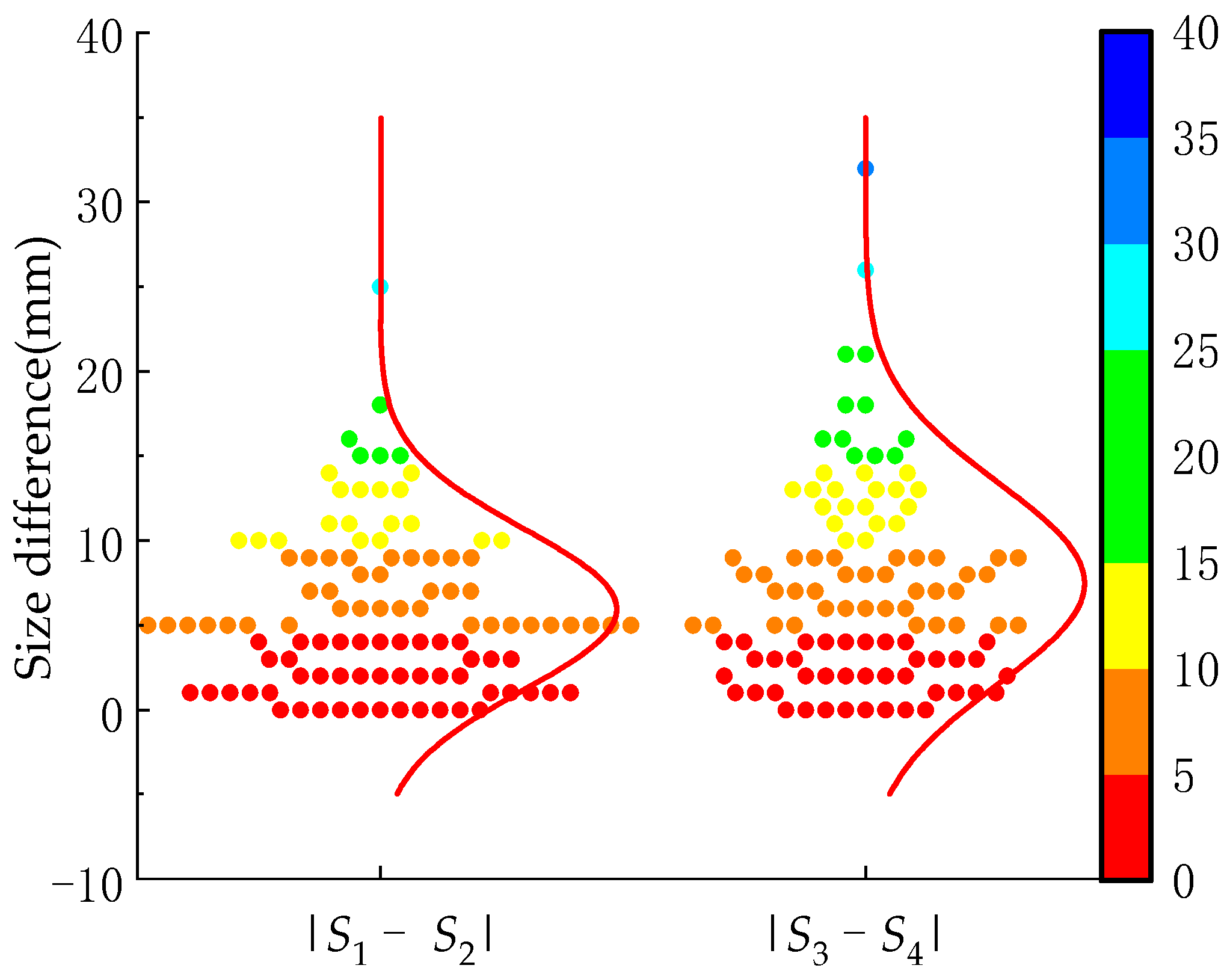
  • Studying the physical characteristics of cotton plants, it was evident that the height of cotton plants exceeded the height of the cotton tops in approximately 98.10% of the selected samples. The average height difference between the cotton plant and the top of the cotton was less than 20 mm. Additionally, 98.10% of the cotton plants had a height difference of less than 50 mm from the top of the cotton. This implies that the blades adjacent to the cotton top were positioned closely, making them susceptible to damage during mechanical topping, which can lead to over-topping. Statistically analyzing the size of the outer contour of the cotton top and the adjacent blades, the selected samples showed that the outer contour shape of the top and the surrounding blades was approximately square. The mean size of the cotton tops (S1, and S2) was approximately 42.2 mm, with 95.24% of the sample having tops measuring not greater than 65 mm. The mean size of the parietal blades (S3, and S4) was approximately 83.4 mm, with 90.95% of the sample having blade tops measuring not less than 65 mm. The shear test of the stem top reveals the following measurements in the specimen: (1) an average long side dimension of 3.49 mm, with a maximum of 4.78 mm, and (2) an average shear force of 15.94 N, peaking at 30.56 N. This implies that the farther a cotton plant is from the top, the greater the shearing force on its main stalks. The study of the physical characteristics of the cotton plants reveals several important points. During topping, the height difference between the top of the cotton and the height of the plant is minimal. This means that the leaves and the cotton top are almost at the same height, making it challenging to avoid shaking the top and potentially damaging the leaves when using mechanical topping methods. However, there is a significant size difference between the cotton top and the surrounding leaves. This size disparity creates an opportunity for effectively separating the top of the cotton from the adjacent leaves during topping operations. Additionally, the shear force required decreases as the distance from the top to the stem diminishes. This characteristic facilitates the optimization of shear force settings, allowing for more precise and efficient topping with minimal plant damage.
  • Based on the statistical analysis of the physical characteristics of the cotton plants, a bionic topping manipulator was designed using bionics principles. The design process involved analyzing manual topping methods, studying topping actions, and developing key components. To minimize the over-topping rate of the bionic topping manipulator, a screening grid based on the statistical analysis of the biological parameters of cotton tops was designed. Testing with tops and blades showed that a chosen grid spacing of 40 mm provided a comparatively good screening effectiveness. To achieve the automatic opening and closing of the bionic top-beating manipulator, a direct-acting flat-bottomed follower disc cam mechanism was designed using analytical methods. The base circle radius of the cam was determined to be 6 mm, with the flat-bottomed follower measuring 43 mm. From the mechanical tests of stem-shearing at the top and considering the dimensional parameters of the bionic topping manipulator, it was observed that the tension force of the tension spring should exceed 81.5 N. Based on the structural parameters of the top-beating manipulator, the specifications of the tension spring were calculated as follows: (1) the spring material diameter (d) was 1.6 mm, and (2) an effective number of turns (n) was set at 46. The tension spring exhibited a free length of 88.8 mm and a working length of 113.8 mm, yielding a working tension of 85.03 N.
  • The verification test for topping performance confirmed the bionic topping manipulator’s effectiveness in separating the top within the specified length range (a topping position not greater than 50 mm). Insufficient shearing force outside the top length range (a topping position more than 50 mm) reduced the damage to the cotton plant, although the shearing rate was lower. The bionic topping manipulator underwent functional verification tests with a screening grid installed, achieving a topping rate of 100% and an over-topping rate of 6.67%. This design effectively reduced the over-topping rate and enhanced the reliability of the topping process. Traditional topping methods, such as manual topping and chemical sealing, cannot be fully replaced in the short term. However, based on the current tests, the bionic topping manipulator developed by our team is only a core component of a bionic topping system. It performs the essential topping action with manual assistance and meets the agronomic requirements. From the perspective of reducing labor intensity and environmental impact, this is a promising start. With ongoing advancements in detection, identification, and automation technologies, the bionic topping manipulator is expected to become a more practical solution.

Author Contributions

Conceptualization, Y.X. and C.H.; methodology, Y.X., J.Z. and B.H.; software, Y.X.; validation, Y.X. and J.Z.; formal analysis, C.H., X.M. and H.M.; data curation, Y.X. and J.Z.; writing—original draft preparation, Y.X. and C.H.; writing—review and editing, Y.X., C.H. and J.Z.; supervision, C.H., H.M. and B.H.; project administration, C.H.; funding acquisition, C.H. All authors have read and agreed to the published version of the manuscript.

Funding

This study was supported by the National Key Research and Development Program of China (2022YFD2002401), the “Spark Technology” Cultivation Project of the Department of Science, Technology and Education of the Ministry of Agriculture and Rural Affairs (13230369), the Open Project of the Key Laboratory of On-Site Processing Equipment for Agricultural Products of the Ministry of Agriculture and Rural Affairs (2016NYZD2304), the Xinjiang Uygur Autonomous Region Tien Shan Innovation Team Project (2021D14010), and the Graduate Student Innovation Program of Xinjiang Uygur Autonomous Region (XJ2022G130).

Institutional Review Board Statement

Not applicable.

Data Availability Statement

Data are contained within the article.

Acknowledgments

We thank our team members for their collaborative effort. We also appreciate the editor and anonymous reviewers for their helpful suggestions to improve the quality of this manuscript.

Conflicts of Interest

The authors declare no conflicts of interest.

References

  1. National Bureau of Statistics. China Statistical Yearbook; China Statistical Press: Beijing, China, 2023. [Google Scholar]
  2. Yang, Y.; Ouyang, Z.; Yang, Y.; Liu, X. Simulation of the effect of pruning and topping on cotton growth using cotton2k model. Field Crops Res. 2008, 106, 126–137. [Google Scholar] [CrossRef]
  3. Kittock, D.L.; Fry, K.E. Effects of topping pima cotton on lint yield and boll retention. Agron. J. 1977, 69, 65–67. [Google Scholar] [CrossRef]
  4. Bennett, O.L.; Ashley, D.A.; Doss, B.D.; Scarsbrook, C.E. Influence of topping and side pruning on cotton yield and other characteristics. Agron. J. 1965, 57, 25–27. [Google Scholar] [CrossRef]
  5. Gu, S.; Evers, J.; Zhang, L.; Mao, L.; Zhang, S.; Zhao, X.; Liu, S.; Van der werf, W.; Li, Z. Modelling the structural response of cotton plants to mepiquat chloride and population density. Ann. Bot. 2014, 114, 877–887. [Google Scholar] [CrossRef] [PubMed]
  6. Llandres, A.L.; Raki, A.; Thierry, B.; Alain, R.; Idrissa, T.; Janine, J.; Goebel, F. Plant training for induced defense against insect pests: A promising tool for integrated pest management in cotton. Pest Manag. Sci. 2018, 74, 2004–2012. [Google Scholar] [CrossRef] [PubMed]
  7. Zhao, W.; Du, M.; Xu, D.; Lu, H.; Tian, X.; Li, Z. Interactions of single mepiquat chloride application at different growth stages with climate, cultivar, and plant population for cotton yield. Crop Sci. 2017, 57, 1713–1724. [Google Scholar] [CrossRef]
  8. Renou, A.; Idrissa, T.; Togola, M. Manual topping decreases bollworm infestations in cotton cultivation in mali. Crop Prot. 2011, 30, 1370–1375. [Google Scholar] [CrossRef]
  9. Dai, J.; Tian, L.; Zhang, Y.; Zhang, D.; Xu, S.; Cui, Z.; Li, Z.H.; Li, W.J.; Zhan, L.J.; Li, C.D. Plant topping effects on growth, yield, and earliness of field-grown cotton as mediated by plant density and ecological conditions. Field Crops Res. 2022, 275, 108337. [Google Scholar] [CrossRef]
  10. Zhang, J.; Zheng, C.; Zhao, J.; Zhang, R.; Zhao, X.; Li, F. Design and test of automatic row alignment device for cotton topping machine. J. Agric. Mach. 2021, 52, 93–101. [Google Scholar]
  11. Han, C.; Yan, C.; Qiu, S.; Xu, Y.; Hu, B.; Mao, H. Design and experiment of double disc cotton topping device based on machine vision. Trans. Chin. Soc. Agric. Mach. 2023, 54, 36–46. [Google Scholar]
  12. Xie, Q.; Kong, F.; Shi, L.; Chen, C.; Wu, T.; Sun, Y. Progress of key technologies for mechanical topping of cotton. Chin. J. Agric. Mech. Chem. 2023, 44, 28–34. [Google Scholar] [CrossRef]
  13. Griffith, T.K. Cotton Topper. U.S. Patent 0852715, 7 May 1907. [Google Scholar]
  14. Schwarz, O. Cotton Topper. U.S. Patent 0897935, 8 September 1908. [Google Scholar]
  15. Lowrey, L.A. Cotton Topper. U.S. Patent 1002412, 5 September 1911. [Google Scholar]
  16. Bell, J.W. Cotton Topper. U.S. Patent 2578963, 18 December 1951. [Google Scholar]
  17. Hu, B.; Wang, W.X.; Li, S.L.; Li, M.Z. Experimental study on 3MD-12 cotton topping machine. China Agric. Mech. 2004, 41–42. [Google Scholar]
  18. Peng, Q.; Kang, J.; Song, Y.; He, Q. Design of 3MDZ-4 self-propelled cotton topdressing and spraying combined operation machine. J. Agric. Eng. 2019, 35, 30–38. [Google Scholar]
  19. Deng, X.L.; Luo, Z.W.; Pang, J.Q.; Zhang, Y.M.; Yang, C.J.; Li, R.Q. Design and experiment of bionic nondestructive handheld suction apple picker. J. China Agric. Univ. 2019, 24, 106–114. [Google Scholar]
  20. Hayashi, S.; Shigematsu, K.; Yamamoto, S.; Kobayashi, K.; Kohno, Y.; Kamata, J.; Kurita, M. Evaluation of a strawberry-harvesting robot in a field test. Biosyst. Eng. 2010, 105, 160–171. [Google Scholar] [CrossRef]
  21. Gao, J.; Zhang, F.; Zhang, J.; Guo, H.; Gao, J. Picking patterns evaluation for cherry tomato robotic harvesting end-effector design. Biosyst. Eng. 2024, 239, 1–12. [Google Scholar] [CrossRef]
  22. Li, M.; Liu, P. A bionic adaptive end-effector with rope-driven fingers for pear fruit harvesting. Comput. Electron. Agric. 2023, 211, 107952. [Google Scholar] [CrossRef]
  23. Pi, J.; Liu, J.; Zhou, K.; Qian, M. An octopus-inspired bionic flexible gripper for apple grasping. Agriculture 2021, 11, 1014. [Google Scholar] [CrossRef]
  24. Zhao, J.; Wang, X.; Zhuang, J.; Liu, H.; Wang, Y.; Yu, Y. Coupled bionic design based on primnoa mouthpart to improve the performance of a straw returning machine. Agriculture 2021, 11, 775. [Google Scholar] [CrossRef]
  25. Aydın, İ.; Arslan, S. Mechanical properties of cotton shoots for topping. Ind. Crops Prod. 2018, 112, 396–401. [Google Scholar] [CrossRef]
  26. Hao, H.; Wu, S.; Li, Y.K.; Wen, W.; Fan, J.; Zhang, Y.; Zhuang, L.; Xu, L.; Li, H.; Guo, X.; et al. Automatic acquisition, analysis and wilting measurement of cotton 3d phenotype based on point cloud. Biosyst. Eng. 2024, 239, 173–189. [Google Scholar] [CrossRef]
  27. Esgici, R. The effect of knife type on cutting characteristics of cotton stalk. Fresenius Environ. Bull. 2020, 29, 2772–2777. [Google Scholar]
  28. Zhao, Y.; Tang, Z.; Chen, S. Loading model and mechanical properties of mature broccoli (Brassica oleracea L. var. italica plenck) stems at harvest. Agriculture 2022, 12, 1519. [Google Scholar] [CrossRef]
  29. Van Henten, E.J.; Van’t Slot, D.A.; Hol, C.W.J.; Van Willigenburg, L.G. Optimal manipulator design for a cucumber harvesting robot. Comput. Electron. Agric. 2009, 65, 247–257. [Google Scholar] [CrossRef]
  30. Zhang, B.; Chen, X.; Zhang, H.; Shen, C.; Fu, W. Design and performance test of a jujube pruning manipulator. Agriculture 2022, 12, 552. [Google Scholar] [CrossRef]
  31. Islam, M.N.; Iqbal, M.Z.; Ali, M.; Chowdhury, M.; Kabir, M.S.N.; Park, T.; Kim, Y.J.; Chung, S.O. Kinematic analysis of a clamp-type picking device for an automatic pepper transplanter. Agriculture 2020, 10, 627. [Google Scholar] [CrossRef]
  32. Luo, B. Basic dimensioning of direct-acting flat-bottomed follower disk cam mechanisms. Appl. Sci. Technol. 2002, 29, 54. [Google Scholar]
  33. Liu, C.; Liu, Q.; Cai, C. Practical Design Manual of Automatic Mechanical Cam Mechanism; Science Press: Beijing, China, 2013; pp. 91–115. [Google Scholar]
  34. Cheng, D. Mechanical Design Manual (Single-Volume): Springs, 6th ed.; Chemical Industry Press: Beijing, China, 2017; pp. 15–42. [Google Scholar]
Figure 1. Schematic diagram for measuring the biological characteristics of cotton plants.
Agriculture 14 01469 g001
Figure 2. Normal distribution curves of cotton plant physical parameters: (a) Cotton plant height distribution statistics; (b) cotton top height distribution statistics; (c) cotton top length distribution statistics; (d) distribution of height difference between cotton plant height and top height statistics.
Agriculture 14 01469 g002
Figure 3. Size distribution of cotton tops and parietal blades next to the top.
Agriculture 14 01469 g003
Figure 4. Difference in side lengths of the outer rectangular contour of the cotton top and the blade next to the top.
Agriculture 14 01469 g004
Figure 5. Schematic illustration of the location of stem cross-section size measurements under the cotton top.
Agriculture 14 01469 g005
Figure 6. Measurements of stem cross-section dimensions under the cotton top: (a) Position 1; (b) position 2; (c) position 3; (d) position 4.
Agriculture 14 01469 g006aAgriculture 14 01469 g006b
Figure 7. Schematic diagram of the location of the stem shear force test at the top of cotton.
Agriculture 14 01469 g007
Figure 8. Cotton top shear topping test method and shear load–displacement curve of the stem at the top of cotton: (a) Cotton top shear topping test method; (b) shear load–displacement curve of the stem at the top of cotton.
Agriculture 14 01469 g008
Figure 9. Manual topping method.
Agriculture 14 01469 g009
Figure 10. Schematic structure and working principle of the bionic topping manipulator: (a) Schematic structure; (b) Working principle. 1. Cam. 2. Fixed mounting shaft. 3. Connecting arm. 4. Flat-bottomed follower. 5. Push rod. 6. Cover shell. 7. Tension spring. 8. Pinch finger. 9. Screening grid.
Agriculture 14 01469 g010
Figure 11. Sketch of the structure of the bionic topping manipulator: 1. Cam, 2. Flat-bottomed follower, 3. Pinch finger articulation point, 4. Pinch finger, 5. Tension spring.
Agriculture 14 01469 g011
Figure 12. Designed screening grids of different sizes.
Agriculture 14 01469 g012
Figure 13. Sketch of the structure of the disc cam mechanism of the direct-acting flat bottom follower.
Agriculture 14 01469 g013
Figure 14. Schematic diagram of the relationship between spring force and clamping force.
Agriculture 14 01469 g014
Figure 15. Schematic diagram of the method of separating tops and blades for different sizes of screening grids: (a) Schematic representation of the downward distance marking method; (b) test method schematic.
Agriculture 14 01469 g015
Figure 16. Illustration of the top and blade screening test: (a) Only cotton tops passes; (b) cotton tops and parietal blades through; (c) none passes.
Agriculture 14 01469 g016
Figure 17. Schematic diagram of the verification test of the top-shearing performance of the bionic topping manipulator: (a) Marking of topping positions; (b) status of field trials.
Agriculture 14 01469 g017
Figure 18. Bionic topping manipulator topping performance verification test.
Agriculture 14 01469 g018
Figure 19. Obstruction of top by crop points of the screening grid (a) Screen intersections prevent cotton tops from passing through the screening grid; (b) cotton tops are broken (separated) by the downward moving sieve grids and the stalks pass through the screening grids; (c) Cotton tops are broken by the downward-moving screening grids, and the stalks and tops do not pass through the screening grids.
Agriculture 14 01469 g019
Figure 20. Topping effect: (a) Over-topping; (b) topping qualified.
Agriculture 14 01469 g020
Table 1. Test results of different specifications of screening grids.
Experiment NumberScreening Grid SpecificationsDownward Depth/mmNumber of Trials/PlantNumber of Tops Passing through the Screening Grid/PlantNumber of Blades Passing through the Screening Grid/PlantTop Passing Rate/%Top Side Blade Passing Rate/%
1Small50 mm3019263.336.67
2Medium50 mm3029496.6713.33
3Large50 mm30302510083.33
Table 2. Top shear performance verification test results.
Experiment NumberTopping Position (h)/mmNumber of Trials /PlantNumber of Cotton Tops Removed/PlantShear Rate/%
1403030100%
2503030100%
360301756.67%
Table 3. Bionic topping manipulator topping performance verification test results.
Experiment NumberWhether or Not a Screening Grid Is InstalledNumber of Trials
/Plant
Number of Blades Passing through the Screening Grid/PlantNumber of Blades Damaged/PlantTopping
Rate/%
Over-Topping
Rate/%
1Not30/2110070.00
2Yes30621006.67
Disclaimer/Publisher’s Note: The statements, opinions and data contained in all publications are solely those of the individual author(s) and contributor(s) and not of MDPI and/or the editor(s). MDPI and/or the editor(s) disclaim responsibility for any injury to people or property resulting from any ideas, methods, instructions or products referred to in the content.

