Article

Design and Experiment of Double-Nest Eye-Type Hole-Wheel Dense-Planting Wheat Dibbler

1
College of Mechanical and Electrical Engineering, Shihezi University, Shihezi 832000, China
2
College of Mechanical and Electrical Engineering, Tarim University, Aral 843300, China
*
Author to whom correspondence should be addressed.
Agriculture 2024, 14(9), 1489; https://doi.org/10.3390/agriculture14091489 (registering DOI)
Submission received: 31 July 2024 / Revised: 23 August 2024 / Accepted: 23 August 2024 / Published: 1 September 2024
(This article belongs to the Section Agricultural Technology)

Abstract

:
To address the problems of the inaccurate seeding rate and uneven seeding in the process of dense planting of winter wheat in Xinjiang, according to the physical characteristics of the wheat seeds and the agronomic requirements of the high-yield cultivation techniques for the winter wheat “well” type, a double-hole wheel-type densely planted wheat hole sower was designed and produced. Through theoretical design and research, the structural design of the overall hole seeder and its key components was completed. The findings indicated that 5–7 wheat seeds could be planted in each hole at a 9.2 mm nest depth and 610 mm3 nest volume, which was consistent with the “well”-type high-yield dense-planting cultivation technology’s need for 400,000–500,000 basic seedlings per mu. The rotation speed and the quantity of the wave guide teeth were used as test factors and the qualifying index, replay index, and missed sowing index were used as test indicators to create the two-factor, three-level central composite design center combination test. It was possible to derive the mathematical model connecting the test factors and test indexes. The regression model underwent multi-objective optimization using the Design-Expert 13 program to determine the optimal parameters: the qualifying index was 91.24%, the replay index was 6.14%, and the missed seeding index was 2.62% when the wave guide rail had four teeth and the seed drill rotated at a speed of 40 revolutions per minute. The best parameter combinations were used for a bench verification test, and the test indicated that the qualified index was 90.25%, the replay index was 4.59%, and the missed broadcast index was 5.16%. The results demonstrated that the densely planted wheat hole seeder performs well, satisfies the requirements for winter wheat dense-planting and sowing operations, and serves as a model for the densely planted wheat hole seeders that will be optimized in the future.

1. Research Highlights

  • We designed the overall structure and key components of a double-hole-type hole-wheel close-planting wheat dibbler.
  • The filling condition of the double-socket seeder was verified byEDEM 2020 discrete element simulation.
  • Through EDEM 2020 and RecurDyn 2023 joint simulation, the working performance of the dibbler was verified.
  • The results of the bench test showed that the designed dense-planting wheat dibbler meets the standard of a high yield and dense planting of “well”-type wheat.

2. Introduction

As one of China’s three main food crops, wheat is strategically important to the country’s food supply and production worldwide in terms of wheat production in 2022–2023 [1]. The top three regions are China, the European Union and India, with production proportions of 17.5%, 17% and 13.2%, respectively [2,3]. The amount of wheat planted and produced in my nation is among the best in the world. In order to guarantee residents’ food supply, maintain national food security, and optimize their diet structure, it is a crucial ration and processing raw material. The country’s new round of grain production capacity improvement actions of 100 billion kilograms has been the focus of the Xinjiang Uygur Autonomous Region in recent years. High-yield key technologies have been integrated, high-yield research and experimental demonstrations have been actively carried out, and wheat yield levels have consistently reached new highs [4]. With the continued development of Xinjiang’s wheat industry, the concept of dense planting and sowing is gradually being widely accepted and implemented.
It is currently difficult to scientifically control the sowing rate and uniformity due to the small wheat seed particles and low sowing accuracy. This will lead to issues like low unit yield, inconsistent sowing depth, and uneven seed distribution, which will cause an imbalanced development of wheat ontogeny. Subsequently, the occurrence of both large and small seedlings emerges, leading to notable variations among wheat individuals and irregular growth [5]. The production and quality of wheat have been negatively impacted by this imbalanced growth and development, which has also emerged as a major barrier to the steady growth of the wheat sector. In order to effectively solve the problems existing in the current technology, the “Southern Xinjiang Cultivation Technical Regulations for 700 kg Winter Wheat per Unit Yield by Dropper” propose that to improve the production level of winter wheat and improve its benefits, the technical route of sowing at an appropriate time, rationally dense planting, reducing height, reducing tillering, and panicle formation from the main approach should be followed. Precise and quantitative sowing operations have become a trend for wheat production due to the development of dense-planting sowing technology, which aims to boost wheat output. The hole-sowing method described in this work may actually plant wheat seeds in a single hole while still meeting the requirements of “well”-shaped high-yield farming technology. In addition to saving seeds and lowering production costs, the requirement for multiple grains during sowing can effectively guarantee the relative positions of wheat planting rows and plant spacing as well as the balanced distribution of water, soil, nutrients, light, and other resources during wheat growth. This can boost the grain yield and raise the wheat survival rate [6].
The hole seeder can be classified into mechanical seeding or pneumatic seeding based on its operating mechanism. At this point, the pneumatic hole seeder’s complex structure, expensive manufacturing and maintenance costs, and limited adaptation to single seeds make it less suitable for larger seeds. Due to the seed’s limited adaptation, it is simple to obstruct the stomata and result in incomplete planting. The mechanical hole seeder is a commonly used tool in production because of its high adaptability, low manufacturing cost, easy maintenance, and simple structural principle [7,8,9]. The two primary categories of mechanical hole seeders now in use in Xinjiang are the hole wheel type and clamping type [10]. The clamping hole seeder, which may be classified as either dynamic fixed-clamping seed taking or splint-clamping disk seed taking based on the various seed-taking modules, uses the clamping principle to finish seed filling. A swing rod clamping hole seeder was created by Wu Haifeng and colleagues [11]. To finish the process of taking seeds, the driving handle and connecting rod are used to drive the seed-taking spoon. The hole seeder’s seed-metering performance is good when its speed exceeds 26.7 r/min; the clamping hole seeder splint chuck was created by [12]. The qualifying rate of seed metering is 90% while the seeder is moving at a speed of 2.1 km/h. Based on the examination, researchers in the country have discovered that the clamping hole seeder has tight requirements in terms of the grain shape and a poor seed cleaning effect has been determined through experimental research [13].
The hole seeder rotates the seed taker by using the wave guide rail to make contact with the rotary rocker arm. This changes the direction of the hole on the seed taker and completes the process of seed filling and seeding. Simultaneously, the relative movement of the wave guide rail and the rotary rocker arm generates a small high-frequency vibration that improves the hole seeder’s ability to clear seeds and disturb populations, as well as its ability to fill seeds [14,15]. In their analysis of the cotton hole seeder’s seed-filling performance, it was discovered that the seeding qualification rate first rises and subsequently falls with increasing vibration frequency. Moreover, a 6.08 Hz vibration frequency is the point at which the seeding qualifying rate reaches its highest, 94.65% [16]. They tested a 24-hole cotton hole drill and discovered that seed flinging can be easily caused by the hole drill’s excessively fast rotation speed. It was discovered through preliminary literature research that the hole-wheel hole drill is currently commonly employed in cotton- and maize-seeding areas. There have not, however, been any pertinent reports on studies conducted on wheat. With the goal of improving the inaccurate seeding rate, uneven sowing, and densely planted sowing, this article attempts to address the issues that currently plague the already used method of sowing wheat. A double-nest eye-type hole-wheel-type dense-planting wheat dibbler is designed based on the physical properties of wheat and the agronomic needs of dense planting and sowing. The hole drill’s general structure and essential parts are designed, and the best parameter combination for each part is determined and tested. To evaluate the effectiveness of the rack for seeding with ungraded seeds and to provide a baseline for dense sowing and wheat application in the future, a rack test is carried out.

3. Overall Structure and Working Principle

3.1. Overall Structure of Hole Seeder

A main shaft, a fixed plate, an auxiliary plate, a seed collection mechanism, a core plate, a wave guiding rail, a main plate, and a hole-forming device make up the double-hole-type wheel-type densely planted wheat hole seeder. Twelve seed collection units and a seed collection belt are intended to make up the seed-collecting combination mechanism. A seed collection belt connects each seed collection unit to its two neighboring burrowing devices in the front and back, and the new winter seed collection unit specified in the technical requirements is chosen. The research object is No. 20 coated wheat seeds, and Figure 1 depicts the general structure.

3.2. Working Principle

The lower seed tube allows wheat seeds from the seed box to enter the hole seeder’s seed cavity when the densely planted wheat hole seeder is operating. Under the effect of gravity, the wheat population congregates in the seed-filling area. While the tractor is being pulled, the stationary plate and core The seed collection and assembly mechanism revolves in tandem with the main shaft’s bearing, with the disk remaining stationary. The rotating rocker arm on the seed collection unit and the wave guide rail fixed on the core disk revolve to the seed-filling region of the hole seeder when the unit follows the mechanism for seed collection and assembly. The rotary rocker arm rotates the seed picker when relative motion takes place. The orientation of the double sockets on the seed picker changes from closed to open. At the same time, the rotary rocker arm will generate waves when passing through the wave peaks and troughs of the wave guide rail. Small-amplitude high-frequency vibration enhances the seed clearing and population disturbance capabilities of the seed collection and combination mechanism, and it effectively improves the seed collection performance of the hole seeder. The wheat seeds gathered in the seed-filling area are fully charged under the influence of their own gravity, centrifugal force and inter-species interaction force. Enter the double sockets to complete the seed filling. As the hole seeder moves forward, the seed collection and assembly mechanism drives the seed collection unit to rotate to the seed-clearing area. At this time, the rotary rocker arm on the seed-taking unit breaks away from the wave guide rail, and the excess seeds on the seed-taking device fall back to the seed-filling area under the action of the seed-cleaning brush and gravity. When the seed-taking unit rotates to the seed-carrying area, the rotary rocker arm drives the seed-taking device back to the closed state under the action of the return torsion spring. The seeds in the double sockets quickly escape from the left and right sockets under the action of their own gravity and centrifugal force. The wheat seeds are sent into the adjacent hole-forming devices at the front and rear through the long and short tracks on the seeding bottom plate, respectively. When arriving at the seeding area, as the fixed mouth enters the soil to form a hole, the movable mouth opens under the action of the ground support force, and the wheat seeds fall into the seed hole, completing the sowing operation. The hole seeder can be divided into a seed-filling area, a seed-clearing area, a seed-carrying area, and a seed-throwing area according to its functions and operation zones, as shown in Figure 2.

4. Key Component Design

4.1. Structural Design of Seed Collection Mechanism

In the design process for the hole seeder for the dense planting of wheat, the seed collection mechanism is the core component of the hole seeder, and it is also an important component in direct contact with wheat seeds. Its design structure determines the seed-filling performance of the hole seeder. The seed collection combination mechanism is designed to be assembled from a seed collection belt and 12 “interlocked” seed collection units. The structure of the seed collection belt is shown in Figure 3a. Each seed collection unit includes a seed collection base block. The schematic structural diagram of the seeding plate is shown in Figure 3b, and the assembled seed collection mechanism is shown in Figure 3c.
The size of the seed collection mechanism is one of the main parameters in the structural design of the hole seeder, which affects the installation position of the other parts and the overall structural size. Considering that the diameter range of the existing seed collection and combination mechanism is between 300 and 400 mm [17], when the diameter of the seed collection and combination mechanism is selected to a larger value, it is beneficial to improve the seed-filling and seed-cleaning efficiency. Therefore, the diameter of the seed collection belt designed in this article is 345 mm, and the designed processing thickness is 3 mm. The diameter of the main disk and the auxiliary disk is designed to be 385 mm, and the thickness is designed to be 15 mm. When the main disk and the auxiliary disk are fixedly assembled with the hole seeder, they form a distance gap of 20 mm from the seed collection belt, which can adjust the moving mouth of the hole-forming device. It plays a limiting role. Considering that the fixed-nozzle bottom plate needs to be fastened to the seed collection belt with screws, the fixed-nozzle bottom plate with a thickness of 2 mm is designed to facilitate installation. Therefore, the overall peripheral diameter of the hole seeder is designed to be 450 mm, and the thickness is designed to be 105 mm.

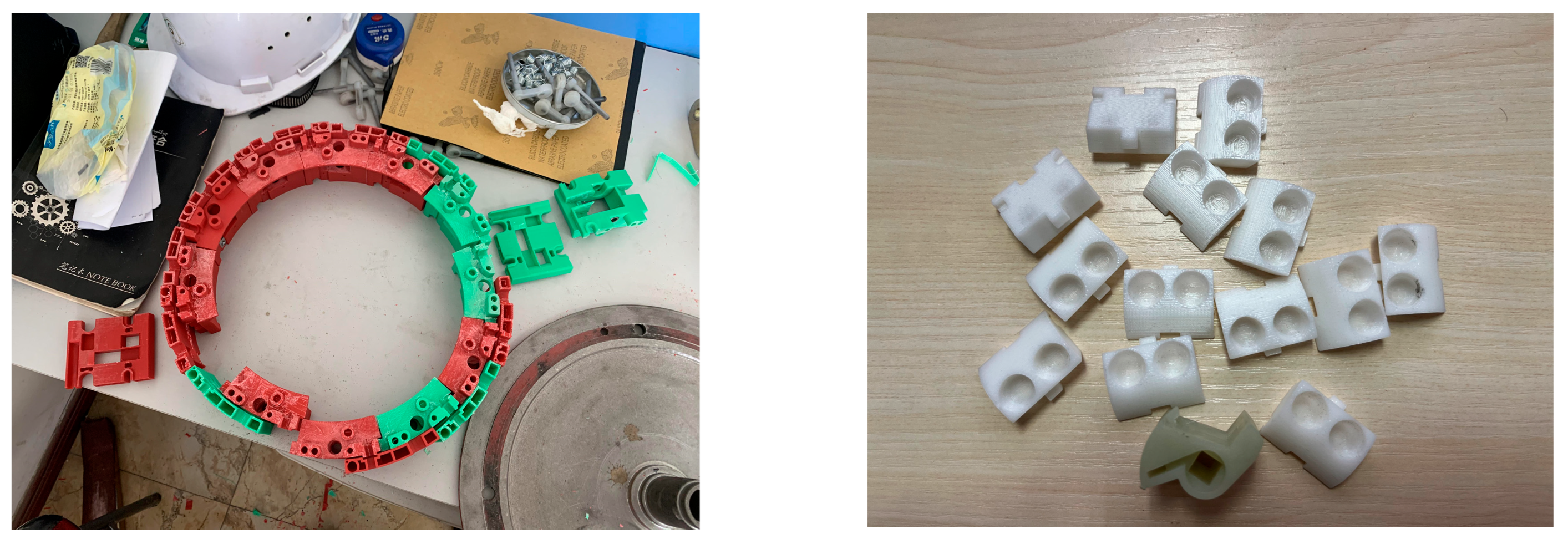
4.2. Structural Design of “Mosaic Structure” Seed Collection Unit

Each seed collection unit consists of a seed collection base block, a seed-throwing bottom plate, a rotary rocker arm, a double-hole seed collection device, a seed collection seat, and a seed-cleaning nylon brush. The structure of the seed collection unit is shown in Figure 4. The seed-taking base block is shown in Figure 5a and the adjacent seed-injecting bottom plate is shown in Figure 5b. It is designed as a “mosaic structure” and adopts an embedded fixation method. This connection method is more convenient. In order to be stable, it can be quickly assembled to obtain a rigid structure with a certain strength, and it is also convenient for later production, installation, maintenance and replacement.

4.2.1. Seed Base Block Structure Design

The seed-picking base block carries the key components for rotating the hole wheel to fill the seeds and clearing the excess wheat seeds. Since the seeding base block and the seeding bottom plate have curved surface characteristics, in the SOLIDWORKS 2024 drawing software, draw the side curve through the sketch module, use the boss extrusion command, set the appropriate datum plane, and use the stretch cut and rotate cut commands for forming. One side of the upper side is designed with an inlay-type punch mold, and the other side is designed with an inlay-type concave mold, as shown in Figure 6. When assembling the seed collection unit, a mosaic-type concave mold is designed on one side of the seed-feeding base plate, corresponding to the mosaic-type convex mold on the seed-collection base block, and a mosaic-type convex mold is designed on the other side. The two are connected through the embedded fixation method, which can shorten the assembly time and obtain good stability at the same time.

4.2.2. Structural Design of Seeding Floor Track

In order to increase the speed of seeding into the hole-forming device after filling the seeds, the seeding bottom plate is designed as a double track composed of a short track and a long track, and the curvature of the track is designed as the fastest descending curve. For the curvature design of the double track, a differential equation is established based on the theoretical model and then the solution of the steepest descent curve is derived using the variation method. The line of the steepest descent can be seen as assuming that A and B are two points on the vertical plane that are not on the same vertical line. Among all the plane curves connecting A and B, find a curve that is only affected by gravity and has an initial velocity of zero. The time required for the particle to move along this curve from point A to point B is the shortest [18], as shown in Figure 7.
Wheat seeds slide from point A to point B, so select the coordinate system. Let the equation of the curve that the particle slides through be such that the mass of the particle is m, the acceleration of gravity is g, and the velocity of the particle slipping is g, where t is the time when the particle slips [19]. According to the Law of Conservation of Energy, at any point during the slide, there are:
1 2 m v 2 ( t ) = m g y ( x )
From this, you can obtain the speed,
v ( t ) = 2 g y
Assuming that the particle slides down, the velocity can be expressed as:
v ( t ) = d s d t d x 2 + d y 2 d t = 1 + y 2 d x d t
So
d t = 1 + y 2 d x v ( t ) = 1 + y 2 2 g y d x
So the time it takes for a particle to slide down from point A to point B is:
Τ [ y ( x ) ] = 0 Τ d t = 0 a 1 + y 2 2 g y ( x ) d x
To keep a function at a minimum, that is, a variational zero,
δ Τ [ y ˜ ( x ) ] = 0
This can order,
F ( y , y ) = 1 + y 2 2 g y ( x )
It is known from the variational method that the extreme value curve satisfies the Euler equation,
F y y f = c
From this, the solution of the equation can be obtained:
y ( 1 + y 2 ) = c
Considering the initial conditions,
y ( 0 ) = 0
There are available,
x = a ( θ sin θ ) y = a ( 1 cos θ )
Here is the radius of the cycloid generation circle, and the angle between the tangent direction of the point and the axis. This is exactly the standard parametric equation for the cycloid, so the path with the shortest time for a particle to slide from point to point is the cycloid [20,21]. The cycloid can pass through the point if the parameter is properly selected, and if the parameter is unique. Through the above theoretical analysis, the mathematical model of the required steepest descent curve is drawn using MATLAB 2021, as shown in Figure 8a, take any point in the red circle on the left picture, and the trajectory of this point is a blue line. The three-dimensional model of the sowing floor track is made using SOLIDWORKS 2024. In order to meet the assembly requirements of the “inlaid structure” seed-taking unit designed by the embedded and fixed method, the sowing floor is also designed with an inlaid convex and concave die, as shown in Figure 8b.

4.3. Hole-Wheel-Type Structural Design

The hole wheel is the core component of the seed-picking unit, and its structural parameters directly affect the filling quality of wheat seeds. As the number of hole-shaped wheels increases, the rotation speed of the hole seeder gradually decreases, and the seed-filling capacity of the socket seed taker increases. However, too many sockets will lead to a smaller gap between the sockets, resulting in poor wheat seed separation and impurity removal. When designing the number of sockets, taking into account the design requirements and the seed-filling effect, the number of sockets for the seed scoop on the hole wheel is designed to be 2.
During the wheat-sowing process, early sowing or late sowing has a greater impact on the growth characteristics and yield of winter wheat. If it is later than the appropriate sowing period, the sowing rate needs to be appropriately increased. At least 0. 5 million basic seedlings need to be added every night [22,23], so the hole wheel is designed as a “mortise and tenon structure” for easy replacement. Each hole wheel is designed with a double-hole seed taker, as shown in Figure 9a, and a seed taker seat, as shown in Figure 9b. The hole wheel is formed by splicing the “tenon” on the double-hole seed collector and the “tongue groove” on the seed seat. The structure is shown in Figure 9c. Through this design, different types of seed takers on the seed seat can be easily replaced according to the actual conditions in the field (such as double-hole seed takers, single-hole seed takers, no-hole spacer seed takers, etc.), and they can also be replaced with seed takers of different sizes and depths (such as a single-seed seed scoop in one hole, a multi-grain seed scoop in one hole, etc.). This double-hole-type hole-wheel-type densely planted wheat hole sower can be suitable for early sowing or the need for late sowing is to achieve “suitability to the site and the right plant at the right time”.

4.3.1. Dimensional Design of Double Socket Seed Taker

The size of the double sockets on the seed scoop needs to be designed with reference to the three-axis dimensions of wheat seeds. Randomly select 300 Xindong No. 20 wheat seeds, and use an electronic counting vernier caliper with an accuracy of 0.01 mm to measure the three-axis dimensions of the wheat seeds. A total of 100 grains were measured in each group, which was repeated three times to take the average [24]. After statistical analysis, the average particle size of Xindong No. 20 wheat seeds was obtained. The data are shown in Table 1. The triaxial diameter of Xindong No. 20 wheat seeds was measured. The mean size is 6.97 × 3.82 × 3.27 mm.
The following equation should be satisfied when designing the dimensional parameters of the fossa,
D = l max + Γ a max < Ε < 3 a min
D is the diameter of each fossa, E is the depth of each fossa, lmax is the maximum length of the wheat seed, Γ is the gap between each fossa and the wheat seed, amax is the maximum thickness of the wheat seed, and amin is the minimum thickness of the wheat seed. The units of the above parameters are all in mm.
In order to meet the dense-planting requirement of 5 to 7 wheat seeds per hole row, the diameter of each socket D and the depth of each socket E should satisfy the following empirical formula.
D = l max + 0.5 ~ 1 mm Ε = l max 0.5 ~ 1 mm
The distance between the socket and the edge of the seed scoop was designed to set aside a margin of 1 mm to ensure that the socket on the double-socket seed picker would not be leaked due to being too close to the edge when 3D printing the seed picker. Therefore, the maximum diameter of each socket was designed to be 11.4 mm and the depth was 9.2 mm.
As the planting method for wheat is a hole of multi-grain dense-planting sowing, in order to improve the adaptability of the eye of the nest to multi-grain wheat seeds, and to ensure that the design of the eye of the nest size to meets the requirements for seed filling, consider the volume of the eye of the nest with reference to the volume of the average value of the 5–7 wheat seeds, combined with the above theoretical analysis, based on the average value of the three-axis dimensions of the wheat seeds measured in Table 1, and substitute it into Formula (14) to arrive at the average value of the volume of the new winter 20 wheat seeds.
V = L × W × T
where L is the mean value of the length of wheat seeds in units mm; W is the mean value of the width of wheat seeds mm, and T is the mean value of the thickness of wheat seeds mm.
The volume of 5~7 wheat seeds was calculated as 435.33~609.46 mm3. The volume of the round table-ball table-type eyelet on the double-eyelet seed extractor can be regarded as the sum of the volume of the round table and the ball table, and the depth of the eyelet was adjusted so that it conformed to the holding space of 5~7 wheat seeds. The maximum size of the fossa is designed as the 5.7 mm radius of the bottom surface of the round table, 4.21 mm radius of the bottom surface of the round table and 6.84 mm height, the radius of the bottom surface of the ball table is the same as the radius of the bottom surface of the round table, the radius of the bottom surface of the ball table is 1.28 mm, and the height of the ball table is 2.36 mm, and the structure is as shown in Figure 10.
V round   table = 1 3 π r 1 2 + 3 r 2 2 + h 2 L 1 V ball   table = π 3 r 3 2 + 3 r 4 2 + h 2 L 2 6 V Fossa   eye = V round   table + V ball   table
where r1 is the radius of the bottom surface on the round table in mm; r2 is the radius of the bottom surface under the round table in mm; r2 is the radius of the bottom surface on the ball table in mm; r3 is the radius of the bottom surface under the ball table in mm; L1 is the height of the round table in mm; and L2 is the height of the ball table in mm.
Substituting the dimensional parameters of the round table and the ball table into the above equation yields a maximum volume of 610.22 mm3 for the nest eye, which satisfies the holding space for 7 wheat seeds.

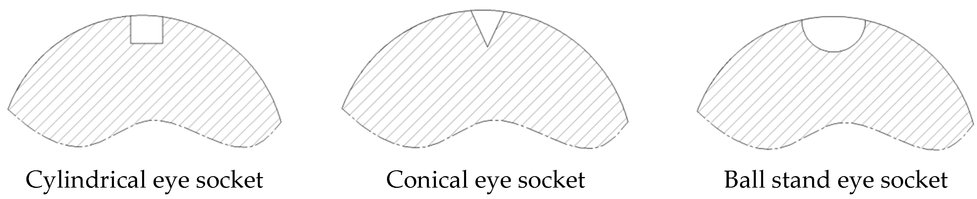
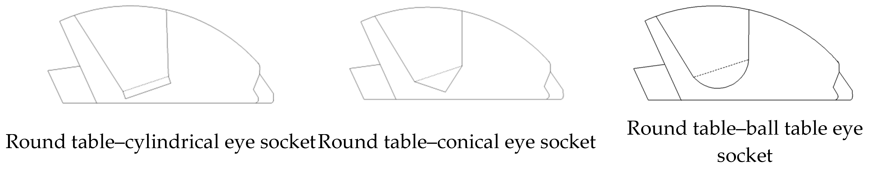
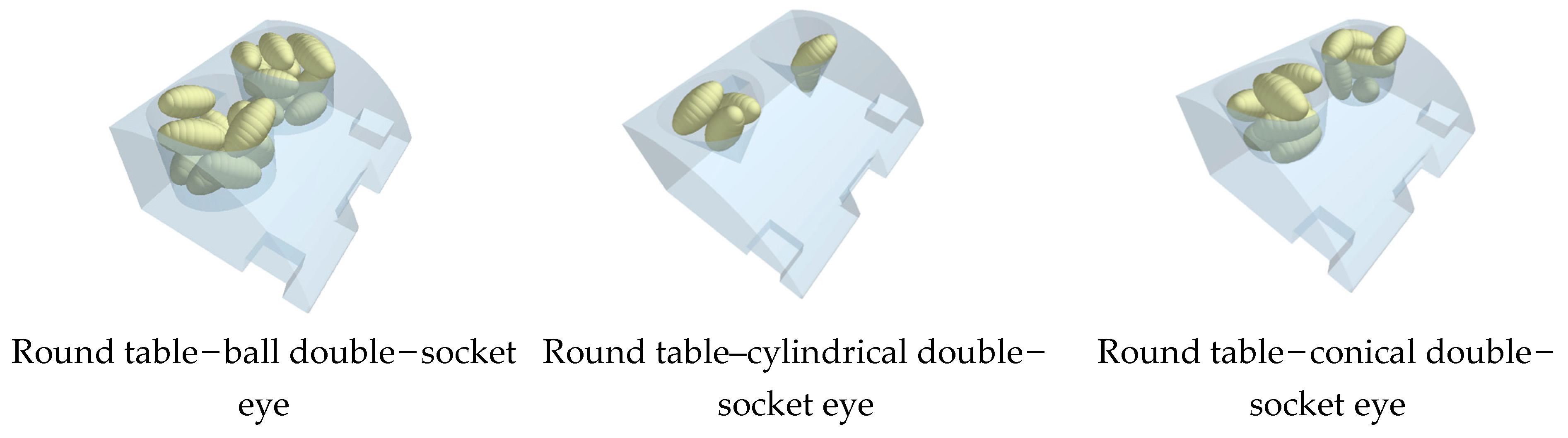
4.3.2. Selection of Double-Socket Shape

The size and shape of the sockets on the seed taker will directly affect the seed-filling performance of the hole seeder [25,26,27]. The size and shape of the sockets are comprehensively determined based on the number of holes and the material characteristic parameters of the seeds [28,29,30]. The common socket shapes are cylindrical, conical and spherical [31,32], as shown in Figure 11.
In the actual operation process, in order to enhance the retention capacity of the wheat seeds in the sockets, and at the same time, to make the wheat seeds in the filling stage fall into the sockets smoothly, the seeds in the planting stage are more likely to enter into the double track of the planting bottom quickly, with reference to the common shape of the sockets, the double sockets are designed as a round table-cylindrical type, a round table-conical column type, and truncated cone-ball table type. The structure is shown in Figure 12.
In order to investigate the seed-filling effect of the above-mentioned three different shapes of seed extraction sockets, the design uses EDEM 2020 discrete element simulation software to compare and analyze the filling of wheat seeds. Each kind of double-fossa seed extractor take seeds 50 times, respectively, set each fossa seed filling 5–7 wheat seeds as qualified, less than 5 or more than 7 as unqualified. For the simulation of the seed filling process, as shown in Figure 13, many rounds of discrete element simulation test analysis show that the qualified rate of seed collection for round table-ball double-socket eye is 92%, round table-cylindrical double-socket eye is 74%, and round table-conical double-socket eye is 32%.
Through a large number of tests, it was found that the cylindrical fossa makes it easy to enter too many wheat seeds during seed filling, resulting in re-seeding; the conical fossa does not easily store multiple wheat seeds during seed filling, resulting in leakage; the dome-shaped fossa is more adaptable to the seeds compared with the first two and has better seeding effect. Therefore, the double-fossa-type orifice wheel is designed as a dome-ball dome-type fossa.

4.4. Structural Design of Cavitation Device

According to the “2023 National Wheat Autumn and Winter Planting Guidelines” issued by the Ministry of Agriculture and Rural Affairs, “the sowing depth is strictly controlled when sowing, so that the row spacing is the same, the amount of sowing is accurate, the depth is the same, and the depth of the sowing is 3 to 5 cm, and the sowing depth is 3 to 5 cm, and there is no leakage and no re-sowing.” In the Xinjiang wheat dense-planting sowing process, the way of spreading film sowing is not used, so the hole-forming device is designed in the form of straight insertion into the soil. The design of the hole-forming device contains a movable nozzle, a fixed nozzle, a hinge moving pin and a reset tower spring, as shown in Figure 14.
The hole former is responsible for the key steps of inserting the seeder into the soil to form holes. A hinge is used to connect the moving nozzle to the fixed nozzle. A return tower spring is fitted to the movable nozzle. The entire cavity-forming device is connected to the periphery of the seed collection combination mechanism by bolts on both sides above the fixed nozzle. In addition, the main and auxiliary discs act as a limiter to prevent the movable nozzle from opening excessively during assembly. Therefore, the construction height of the cavitation device is 65 mm. In the actual sowing process, under the condition that the outer edges of the main disc and the auxiliary disc are 20 mm higher than the seed collecting and combining mechanism, the sowing depth can reach 45 mm, and the length of the formed hole is 25 mm and the width is 25 mm.
In order to make the wheat seeds in the hole-forming device fall into the hole smoothly, the opening and closing degree of the hole-forming device d should meet the following requirements.
d = 1.2 ~ 1.5 a max
The above formula a is the maximum length of wheat seeds, and the maximum opening and closing angle of the hole-forming device is as follows [33]:
ψ max = 2 sin 1 ( d 2 H )
where ψmax is the maximum opening and closing angle of the cavitation device, unit is mm; d is the opening of the cavitation device, unit is mm; and H is the height of the cavitation device in mm.

4.4.1. Quantity Design of Cavitation Devices

The number of hole-forming devices is a significant factor influencing the quality of sowing, and it is also a crucial element of achieving the dense planting and seeding of wheat. When the plant spacing and traction speed are maintained, the greater the number of hole-forming devices, the higher the hole-forming efficiency of the hole seeder will be, which will facilitate the enhanced seed-throwing performance of the hole seeder. The number of hole-forming devices should therefore meet the following requirements [34].
K = π d a L d
Among the mentioned items, K is the number of hole-forming devices, which is expressed as a unit; Ld is the spacing between sowing plants, unit is mm; and da is the maximum diameter of the hole seeder, unit is mm too.
The number of hole-forming devices is a significant factor influencing the seed-filling performance of the hole seeder. In accordance with the agronomic requirements for densely planted wheat sowing in Xinjiang, the seeding rate requirement is to control 400,000 to 500,000 basic seedlings per mu. In consideration of the preceding design experience of hole seeders, the winter wheat dryland plant spacing is 5.8 ± 0.5 cm [35], which takes into account the actual working conditions and errors. Therefore, the sowing hole spacing of the densely planted wheat hole seeder is designed to be 58 mm. As the power required for the hole seeder to operate is derived from the traction of the front power machinery, the speed ratio is not a factor in this context. Subsequent to the calculation conducted in accordance with Equation (18), the value of K was determined to be 24.36. Consequently, the number of hole-forming devices was designed to be 24.

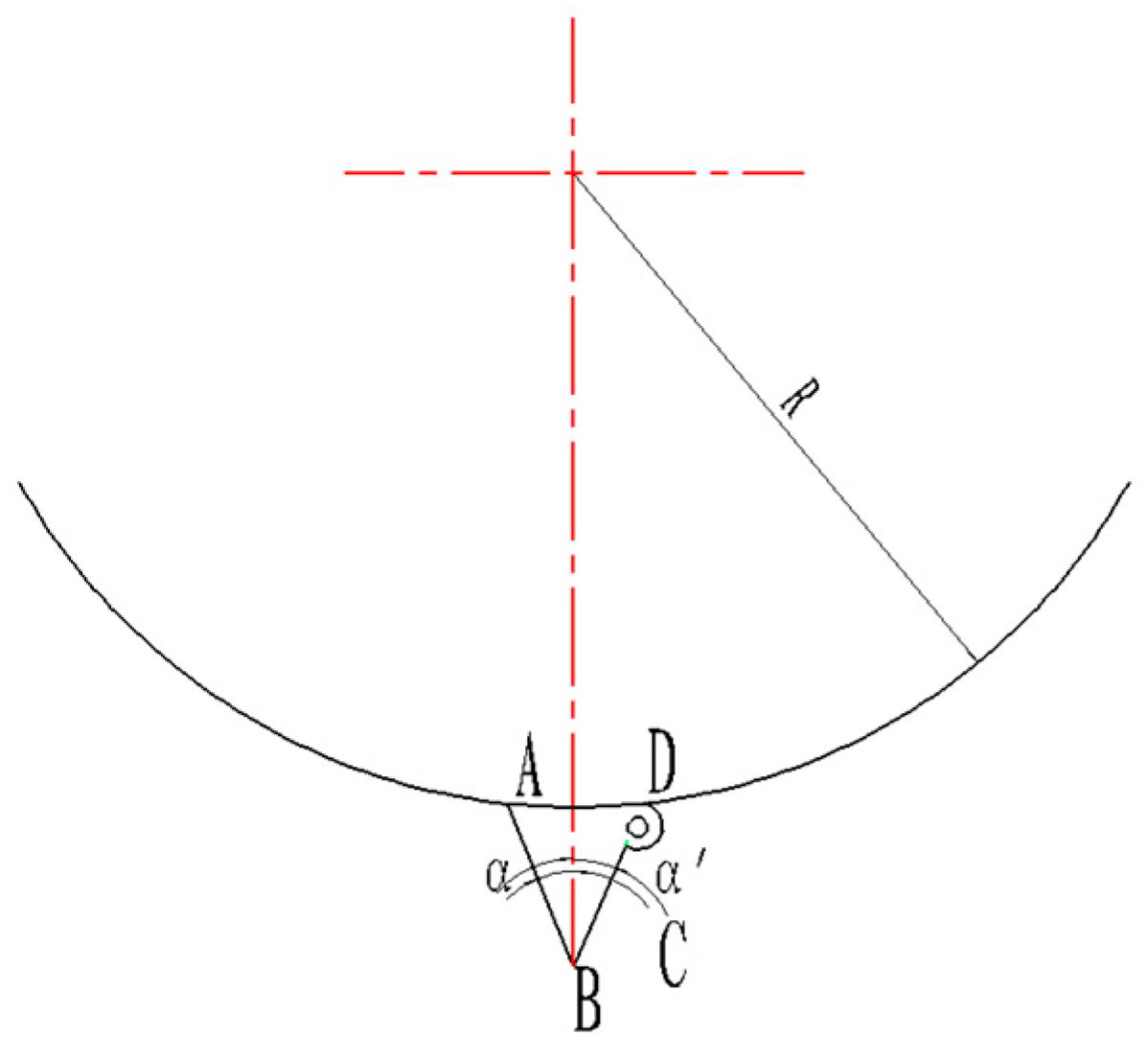
4.4.2. Calculation of Coincidence Degree of Cavitation Device

The coincidence degree of the hole-forming device ε is defined as the ratio of the rotation angle (θ1 + θ2) of the hole-forming device to the corresponding center angle θ0 of the adjacent hole-forming device. As illustrated in Figure 15, the buried point of the hole-forming device is designated as point A and the unearthed point is point B.
θ 1 = θ 2 = arccos ( R R + H )
Consequently, the central angle is calculated to be
θ 0 = 2 π Z
Therefore, the degree of overlap is
ε = θ 1 + θ 2 θ 0 = K π arccos ( R R + H )
It can be seen from the above formula that the degree of coincidence ε is related to the number of hole-forming devices K, the radius of the hole-seeding device R and the sowing depth H. Substitute the numerical values K = 24, R = 222.5 mm, H = 55 mm. Following the completion of the requisite calculations, the degree of coincidence is determined as ε ≥ 1, which reduces the adverse effects caused by slippage and ensures the quality of seeding.

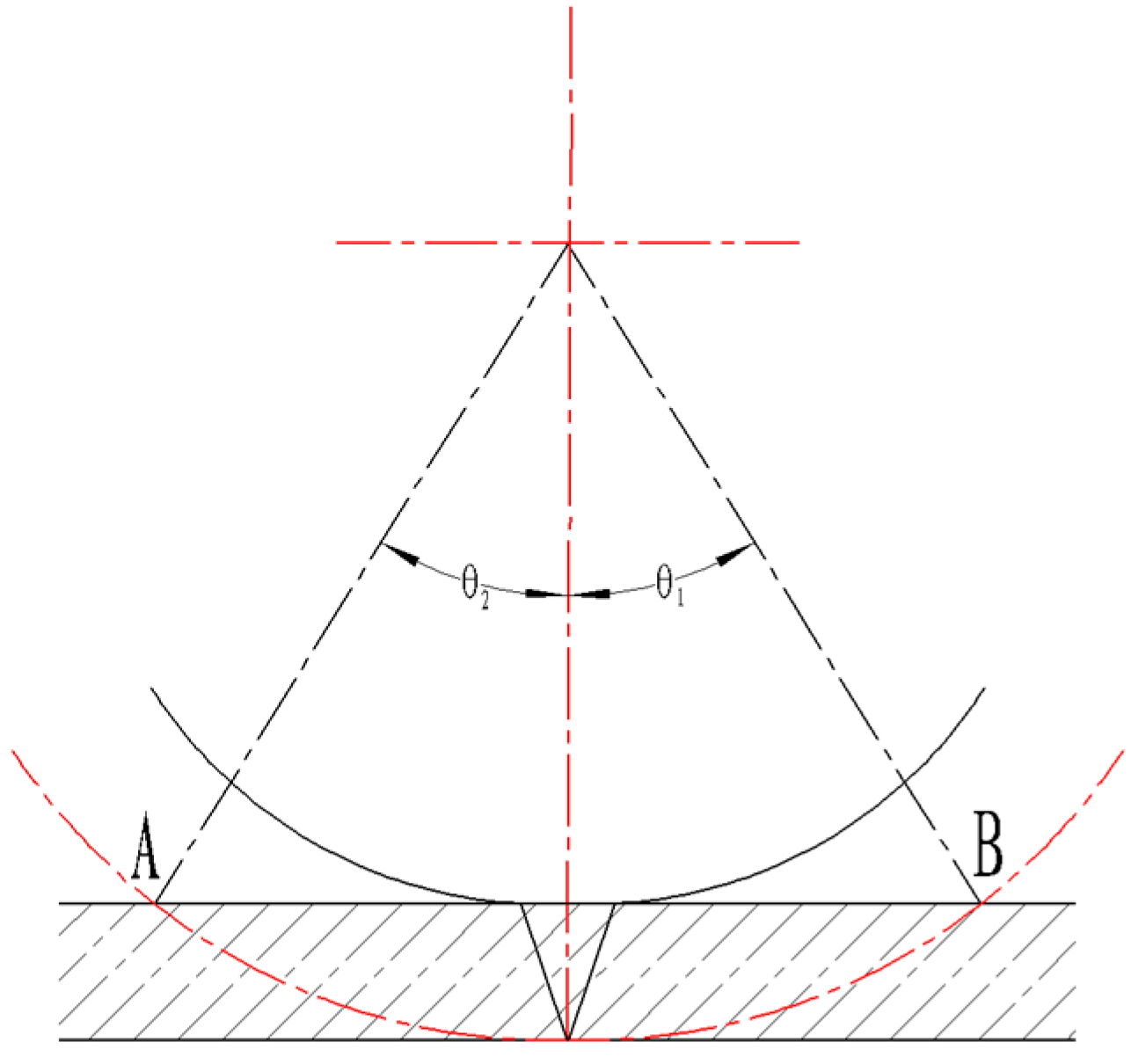
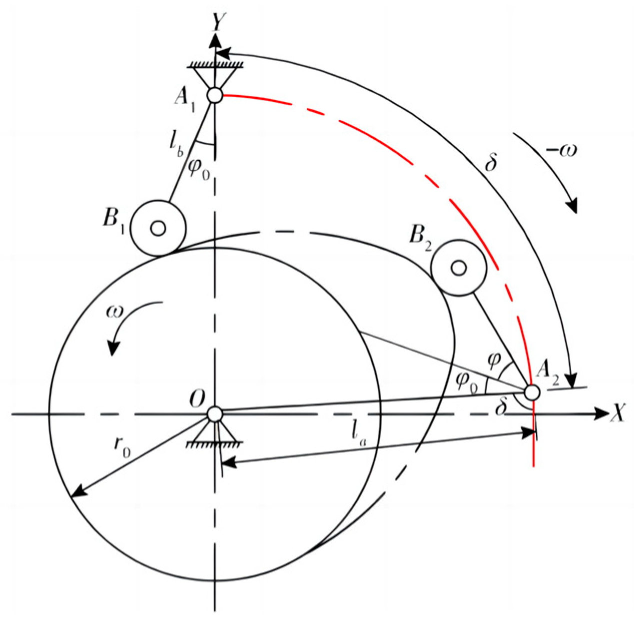
4.4.3. Pressure Angle of Cavitation Device

The size of the fixed-nozzle pressure angle α’ affects the digging performance of the burrowing device and whether the excavation is clean and rapid. It also affects the size of the burrow and the amount of soil movement during excavation. As shown in Figure 16, considering the above situation, it is critical to design a suitable fixed mouth. The pressure angle α of the fixed mouth designed in this article is greater than or equal to θ1 or θ2. The pressure angle α of the fixed mouth in the acupuncture device is generally 15° to 25° [36], and the pressure angle of the movable mouth α’ is equal to α. The structure is symmetrical and the trajectory of the movable mouth point C falls on the trajectory of the fixed mouth point B within the envelope.

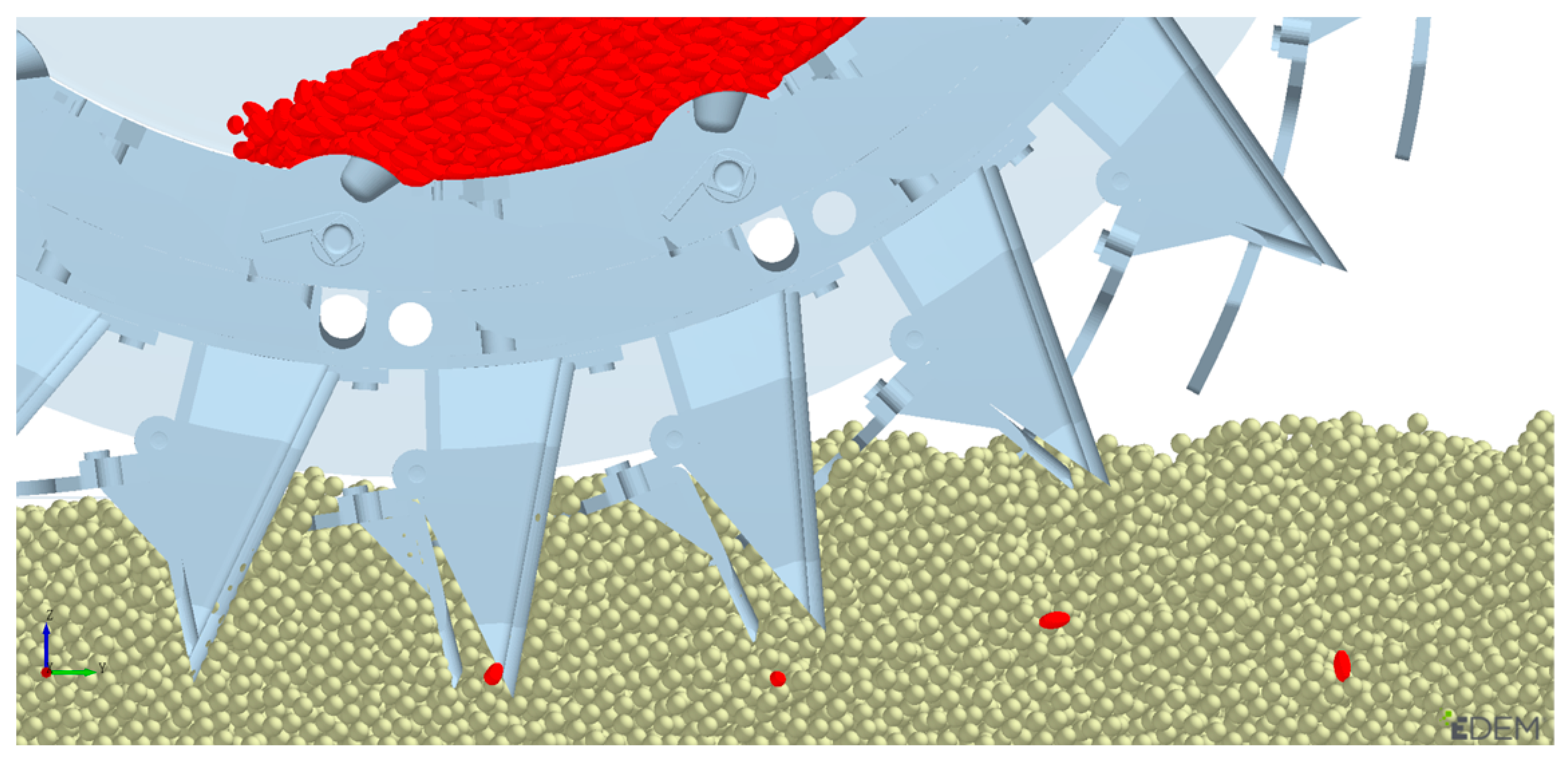
4.4.4. Simulation Analysis of Burrowing Performance of Burrowing Device in Soil

In order to ascertain the dependability of the cavitation device design, a virtual prototype was constructed through the use of NX 12 three-dimensional drawing software, as illustrated in Figure 17. EDEM 2020 discrete element simulation software was employed to simulate the burrowing state of the device in the soil. The soil particles were designated as static generation, whereas the wheat seed generation method was designated as dynamic generation. The experiment was conducted 20 times. To facilitate observation of the position of the wheat seeds introduced into the soil, the coated seeds within the seed cavity are delineated in red, while the soil is assigned the default color, as illustrated in Figure 18.
The opening and closing process of the hole-forming device has been subjected to rigorous testing, and it has been demonstrated that there is no interference whatsoever. Furthermore, the seeding process has been found to be seamless, thereby meeting the requirements for the planting of 24 holes with a high degree of density for wheat cultivation.

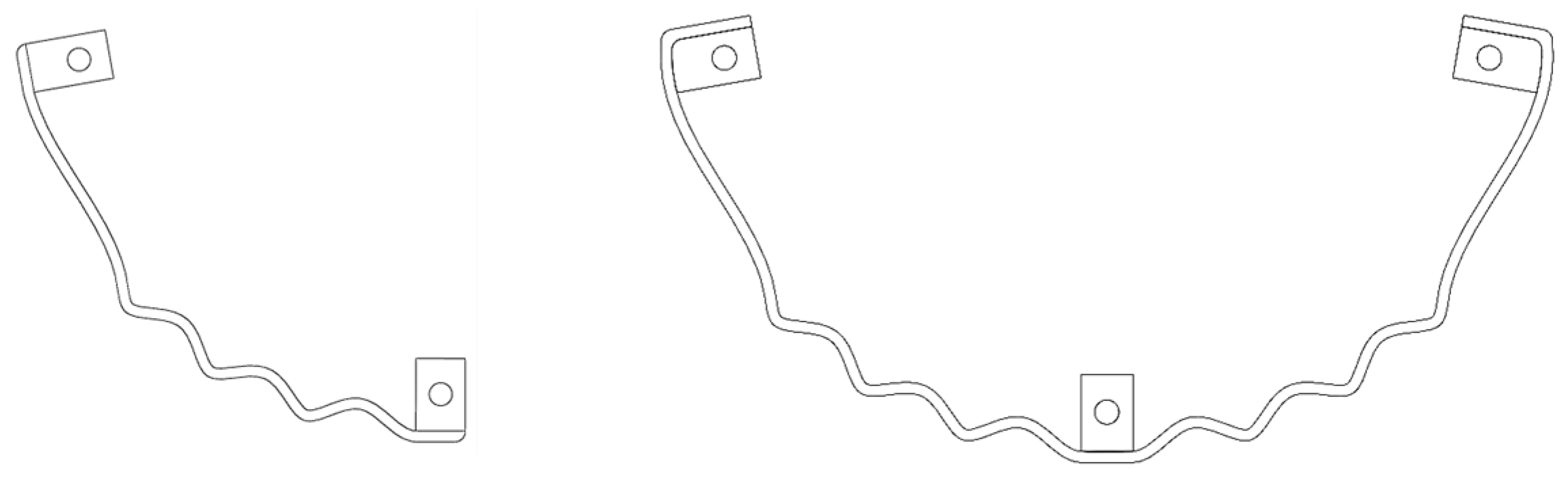
4.5. Design of Wave Guide Rail

The wave guide rail represents a pivotal element of the seed-filling performance of the hole seeder. Upon passing through the wave guide rail, the rotary rocker arm exerts downward pressure on the rotary rocker arm due to the undulations of the tooth shape. This drives the socket seed spoon on the seed taker to rotate and enter the seed-filling stage. Concurrently, the rotary rocker arm path produces small vibrations, which facilitate the removal of excess seeds from the sockets, enhance the seed-cleaning efficiency, and augment certain population disturbance capabilities. Consequently, in order to ascertain the optimal size structure of the wave guide rail, the wave guide rail of the hole seeder was designed.
The arcs on the corrugated guide rail are designed as straight teeth, and the arcs in the rotary rocker arm and corrugated guide rail are simplified into swing rods and cams, respectively. The motion process of the rotary rocker arm through the corrugated guide rail can be transformed into a cam, which then drives the pendulum rod. The process of turning to the highest point B2 of the cam does not take into account the rotational motion caused by the rotational force exerted by the torsion spring on the rotating rocker arm after the latter passes the highest point of the arc. The cam contour line is solved using an analytical method, as illustrated in Figure 19.
The point B2 X sum Y coordinate formula is,
x = l a sin δ l b sin ( δ + ϕ + ϕ 0 ) y = l a cos δ l b cos ( δ + ϕ + ϕ 0 )
Included among these,
ϕ 0 = arccos ( l a 2 + l b 2 r 0 2 ) ( 2 l a l b )
The wave guide rail is installed on the back of the core disk of the hole seeder, so the radius of the tooth tip circle should not be larger than the radius of the core disk, that is,
x 2 + y 2 r s
where la is the distance between the swing lever and the cam rotation center, unit in mm; lb is the length of the swing lever, unit is mm; δ is the cam rotation angle, unit is °; φ is the angular displacement of the swing lever, unit is °; φ0 is the initial position angle of the swing lever, the unit is °; r0 is the base circle radius of the corrugated guide rail, unit in mm; and rs is the radius of the core disk, unit in mm.
It can be calculated from Equation (23), the φ0 for 30°. Also, can be seen from Equation (22) that the coordinates of point B are related to the cam angle δ and the angular displacement of the swing rod φ. The cam rotation angle is generally [37] 55°~75°. When the cam rotation angle δ is 75°, the angular displacement φ is 0.07 rad, and point B coordinates are 111 mm and 60 mm, the maximum radius of the corrugated guide rail is designed to be 126 mm, the thickness of the corrugated guide rail is 3 mm, and the number of straight teeth is between 3 and 7. The configuration of the teeth is illustrated in Figure 20. The number of teeth in the wave guide must be determined based on the results of subsequent tests.

5. Experimental Verification
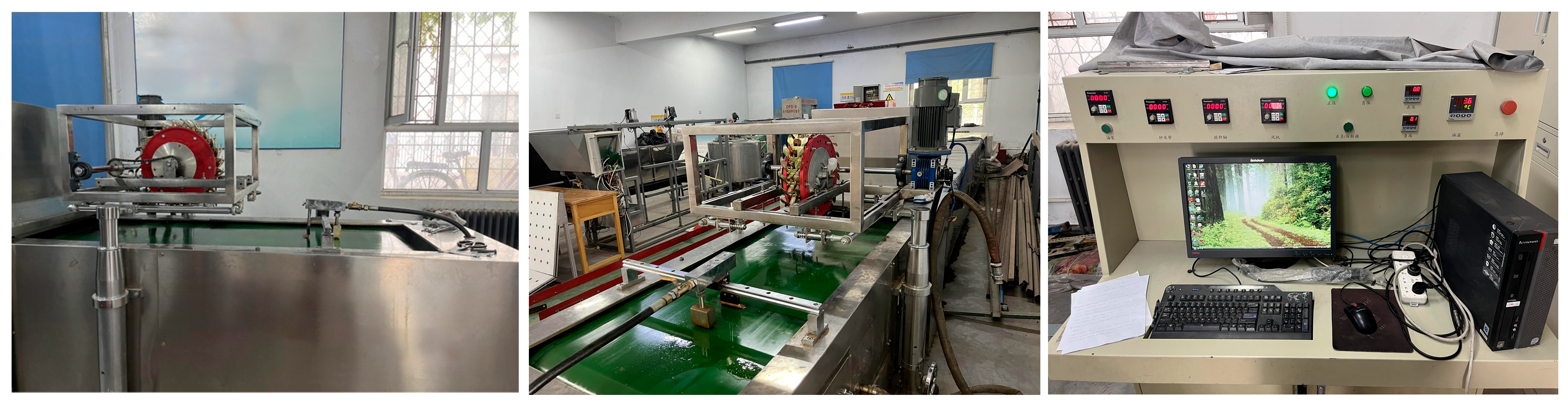
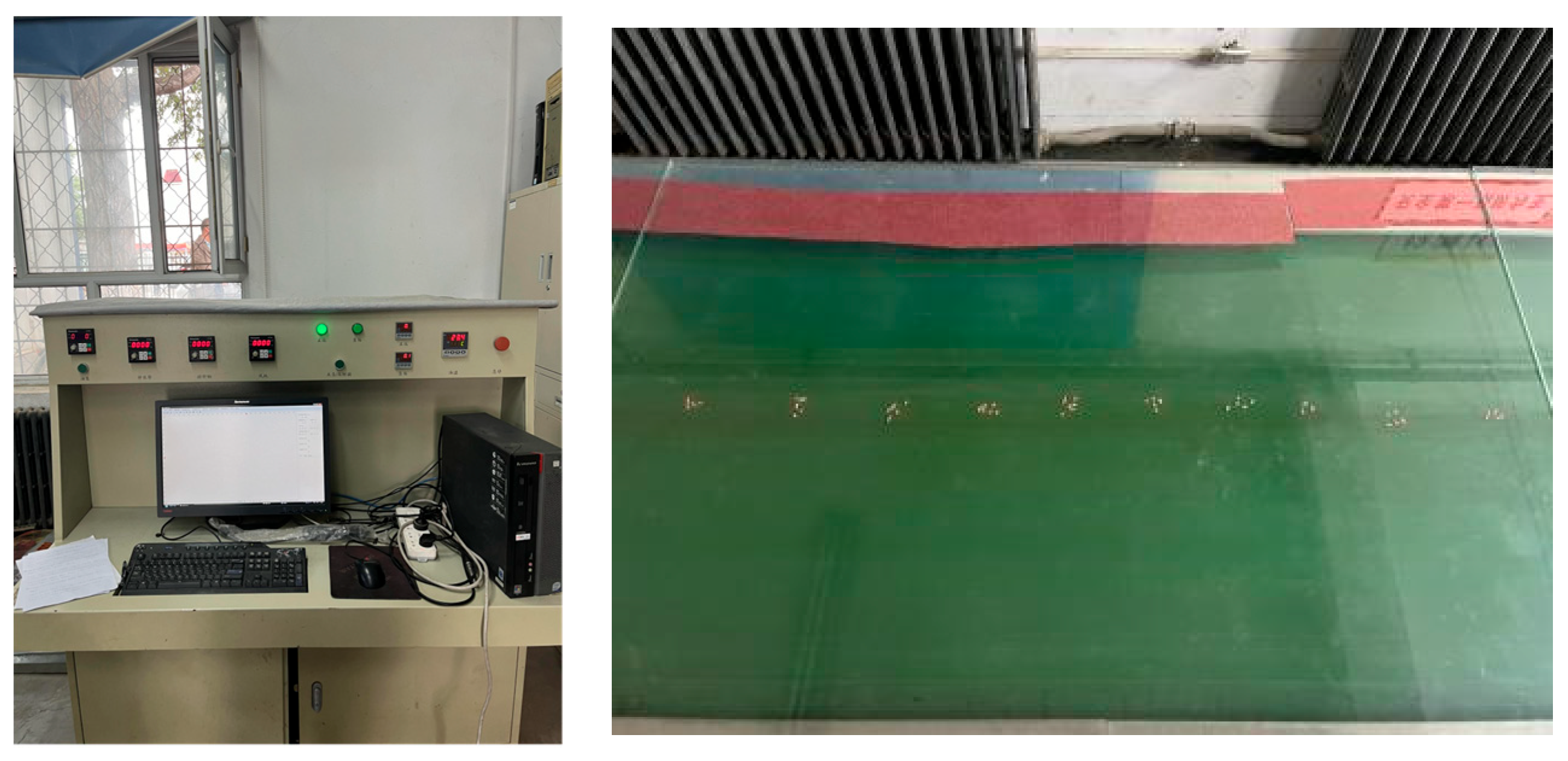
5.1. Test Equipment

The coated wheat seeds Xindong No. 20 were selected for the test in accordance with the technical regulations, with a thousand-grain weight of 49.21 g and a moisture content of 7.58%. The seed collection mechanism was produced using a TierTimes UP-300 3D printer in the 3D-printing laboratory of Shihezi University. The material used was ABS, with a specified accuracy of 0.1 mm, as illustrated in Figure 21.

5.2. Test Indicators

During the seeding test, the seed hopper rotates, causing the seeds to fall onto the hydraulic oil on the seed bed belt through the hole-forming device. Upon passing through the high-speed camera with the conveyor belt, the seeds are captured and detected by the high-speed camera, which then transmits the image to the monitor. The detection process is then completed. In actual field operations, the seeds fall from the opening of the hole-forming device into the seed holes dug by the hole-forming device. Therefore, the seeding spacing is generally the spacing between the hole-forming devices. The seeding sower is mounted on a 24-row wheat seeder, with a row spacing of 150 mm. The hole-forming device is designed to have a plant-to-plant distance of 58 mm. In order to meet the technical requirements for controlling the basic seedlings of densely planted wheat at approximately 400,000 to 500,000 plants per mu in Xinjiang, the number of seeds that should be planted in each hole, that is, the number of seeds in the hole, is calculated as follows:
D = M L Z
where D is the theoretical number of holes per mu in units; M is the number of acres, unit in m2; L is the row spacing, unit is m; and Z is the plant spacing, unit is m.
C = H D
where C is the number of seeds in holes, a is units; H is the basic number of seedlings per mu, a unit is a plant; and D is the theoretical number of holes per mu, the unit is a.
When calculated from the above Formulas (25) and (26), the theoretical number of holes per acre for a 24-row wheat hole seeder equipped with this densely planted wheat hole seeder is 76,667. To meet the requirement of 400,000 basic seedlings per acre, each hole must have at least 5 wheat seeds dropped; when 500,000 basic seedlings per acre are reached, each hole should have no more than 7 wheat seeds.
The reference GB/T6973 is the 2005 “Single-grain (Precision) Seeder Test Method” [38]. The rotation speed of the hole seeder and the number of teeth of the wave guide rail are selected as test factors. The qualification rate R1, the missed sowing rate R2, and the replay rate R3 are designed as the test indicators. The calculation methods for each indicator are as follows. In the seeding bench test, 200 holes of Xindong No. 20 wheat seeds discharged from the hole-forming device were continuously counted as test statistical samples and repeated twice to ensure the reliability of the test results. This approach was employed to avoid the impact of the bench test on the test results due to chance.
J = n J N × 100 % H = n H N × 100 % L = n L N × 100 %
where J is the missed sowing rate, unit is percentage (%); H is the pass rate, unit is percentage (%); L is the replay rate, percentage (%) is unit; nJ is the total number of holes with less than 5 holes; nH is the number of holes with 5 to 7 particles is the total number of holes; nL it is the total number of holes with more than 7 particles; and N is the total number of holes counted in each group of tests. The above units are measured by individual.

5.3. Central Composite Design

Design-Expert 13 software was employed to devise a two-factor, three-level quadratic rotation orthogonal combination test plan. The range of values for each factor was designed as follows: the rotation speed of the hole seeder was set at 30–50 r/min, and the number of teeth on the wave guide rail was set at 3–7. The coding of the test factors is presented in Table 2. Statistical analysis indicates that 5 to 7 seeds per planting are considered to be a sufficient quality, while seeds below 5 or above 7 are deemed to be suboptimal and resown. A central combination test was conducted, and the test design and results are presented in Table 3.

5.4. Test Results and Analysis

Design-Expert 13 software was used to perform regression fitting and variance analysis on the results of the orthogonal test. The variance analysis results of the pass rate, replay rate and missed broadcast rate are shown in Table 4.
As the coefficient of determination R2 was a key indicator of the degree of straight-line fitting of the regression equation, the variance analysis results of the regression equation demonstrate that the coefficient of determination of the pass rate equation R1 was 0.8816. The coefficient of determination of the replay rate equation R2 was 0.8300, while that of the replay rate equation R3 was 0.8172. This indicated that the predicted value of the regression equation has a high correlation with the actual value. The lack-of-fit values were 0.5327, 0.5705, and 0.1693, all greater than 0.05, indicating that the regression equation has a high fitting degree. Therefore, the above equation can be used to optimize the parameters of the densely planted wheat hole seeder.
The primary and secondary factors that affect the test index can be analyzed through the F-value. The primary and secondary factors that affect the pass rate are the number of teeth on the wave guide rail and the rotation speed of the hole drill. The primary and secondary factors that affect the replay rate are the rotation speed of the hole drill and the number of teeth of the wave guide. The order of priority for the missed seeding rate is determined by the rotation speed of the hole-seeding device and the number of teeth on the wave guide rail. In light of the aforementioned analysis, the quadratic polynomial regression equation for the pass rate, replay rate, missed broadcast rate, and the encoding value of the test factors can be expressed as follows:
R 1 = 84.356 + 1.26619 A + 2.43595 B 5.45 A B 3.98 A 2 4.588 B 2
R 2 = 7.91 3.48378 A 3.31582 B + 3.0925 A B + 2.39687 A 2 2.37187 B 2
R 3 = 7.734 + 2.21759 A + 0.87987 B + 2.3575 A B + 1.59112 A 2 + 2.21612 B 2
The regression equation can be subjected to rigorous analysis according to the p-value. Table 4 presents the results of the analysis of variance, which indicates that A has no significant effect on the qualified rate ( p > 0.05 ) , B has a significant effect on the qualified rate ( 0.01 p 0.05 ) , and both AB and A2 and B2 have a significant effect on the qualified rate ( p < 0.01 ) . The regression analysis reveal that AB, A2, and B2 had no significant effect on the replay rate ( p > 0.05 ) . In contrast, A and B had a significant effect on the replay rate ( 0.01 p 0.05 ) , and no item exhibited an extremely significant effect on the replay rate ( p < 0.01 ) . The regression analysis revealed that B and A2 had no significant effect on the mis-seeding rate ( p > 0.05 ) . In contrast, A, AB, and B2 had a significant effect on the mis-seeding rate ( 0.01 p 0.05 ) . Notably, no item demonstrated an extremely significant effect on the mis-seeding rate ( p < 0.01 ) . The quadratic polynomial regression equation that eliminates the insignificant items in the regression equation is as follows:
R 1 = 84.356 + 2.43595 B 5.45 A B 3.98 A 2 4.588 B 2
A similar analysis can be conducted to determine the regression equation for the replay rate and miss rate after eliminating the insignificant items in the regression equation.
R 2 = 7.91 3.48378 A 3.31582 B
R 3 = 7.734 + 2.21759 A + 2.3575 A B + 2.21612 B 2
The response surface generated through the Design-Expert 13 software can effectively illustrate the relationship between the operational performance of the hole seeder and the various test factors. Additionally, it can demonstrate the impact of the interaction between the hole seeder speed and the number of teeth in the wave guide on the pass rate, replay rate, and missed seeding rate. As illustrated in Figure 22, the surface is curved.
When the rotation speed of the hole seeder is held constant, an increase in the number of teeth on the wave guide rail initially results in an elevated seeding pass rate, which subsequently declines. Conversely, when the number of teeth on the wave guide rail is maintained at a constant level, an increase in the rotation speed of the hole seeder leads to a gradual enhancement in the seeding pass rate. This phenomenon can be attributed to the necessity of aligning the number of teeth on the wave guide rail with the rotation speed of the drill seeder. When the rotation speed of the drill is within a narrow range, the likelihood of wheat seeds filling the holes is increased, as illustrated in Figure 22a.
As the number of teeth on the wave guide rail increases, the re-seeding rate gradually increases when the rotation speed of the hole seeder is constant. The rationale for this phenomenon can be attributed to the fact that as the number of teeth on the wave guide rail increases, the opening of excess sockets allows the wheat seeds on both sides of the seed cavity of the hole seeder to fall with greater ease. Upon entering the seeding bottom plate, it can be observed that as the number of teeth on the wave guide rail remains constant, while the re-seeding rate initially decreases and then increases as the rotation speed of the hole seeder increases, as illustrated in Figure 22b.
As the rotation speed of the hole seeder remains constant, the missed seeding rate gradually increases with an increase in the number of teeth of the wave guide rail. The rationale behind this phenomenon can be elucidated by examining the effect of an additional tooth plate on the closing of the seed taker. This results in a reduction in the retention capacity of wheat seeds in the socket, leading to their subsequent falling back into the seed cavity. When the number of teeth of the wave guide rail is held constant, the rotation speed of the hole seeder exerts a dual effect on the missed seeding rate. Initially, it declines, and subsequently, it ascends. This phenomenon is illustrated in Figure 22c.

5.5. Parameter Optimization and Bench Verification Test

In order to identify the optimal combination of factors under the constraints of densely planted wheat hole seeders, a regression equation was solved through multi-objective optimization, with the highest seeding qualification rate, the lowest re-seeding rate, and the lowest mis-seeding rate serving as optimization indicators. The regression equation and constraints are as follows:
M a x R 1 M i n R 2 M i n R 3 s . t . 30 r / min A 50 r / min 3 B 7
Substituting the data into the Design-Expert 13 software, the optimal combination is obtained when the seeding speed is 40 r/min and the number of teeth of the wave guide is 4. At this time, the seeding pass rate of the seeding device is 87.76% and the re-seeding rate is 4.15%. The percentage of missed broadcasts is 8.09%.
To ascertain the veracity of the aforementioned test results and simultaneously evaluate the operational efficacy of the double-hole-type wheel-type densely planted wheat hole seeder, a prototype was constructed via 3D printing and lathe processing. The seed-metering device was then subjected to examination in a small-scale manufacturing facility at Shihezi University. The JPS-12 computer vision seed-metering device performance testing test bench in the laboratory was utilized for the bench test, as illustrated in Figure 23. The speed control knob is utilized to regulate the seeding shaft speed within an adjustable range of 10 to 150 r/min, while the seed bed belt speed is also adjustable. The operational range is 1.5 to 12 km/h, with bench verification tests conducted [39,40,41].
The test was repeated on three occasions, and the mean value was calculated. The number and distribution of the wheat grains on the seed bed conveyor belt can be observed, as illustrated in Figure 24. The computer post-processing software in the data-processing area was employed to obtain the bench test result, which indicated a seeding pass rate of 91.35%. The replay rate is 3.74%, and the missed broadcast rate is 4.91%. The absolute errors of the bench verification test pass rate, replay rate, and missed broadcast rate, as well as the optimization results, are 3.59%, 0.41%, and 3.18%, respectively. The reasons for this discrepancy can be attributed to two primary factors. Firstly, the clamping device utilized to install the hole seeder is not consistently tight when preparing for each bench test, which results in a slight tilt of the hole seeder as the rotational speed increases. Secondly, the tension of the transmission chain that drives the hole seeder to rotate at different values will cause the vibration amplitude of the hole seeder to differ, leading to a larger absolute error. However, this difference falls within the allowable range.

6. Conclusions

(1)
A double-socket hole-wheel-type densely planted wheat hole seeder was designed. Its working principle was analyzed, the overall structure and key components of the hole seeder were designed, and the mathematical relationship between the relative positions of the double-socket seed taker and the sockets was constructed. This model was used to determine the parameters and range that affect the seeding performance of densely planted wheat hole seeders. The central composite design was employed to establish a regression equation between the test indicators and test factors. In addition, the influence rules and interactive relationships of each test factor on test indicators were obtained.
(2)
Design-Expert 13 software was utilized to analyze the test results and perform multi-objective optimization on the regression equation. It can be concluded that the optimal parameter combination is that the rotation speed of the hole seeder was 40 r/min and the number of teeth of the wave guide was 4 teeth. At this juncture, the seeding pass rate was 87.76%, the replay rate was 4.15%, and the missed broadcast rate was 8.09%. The results of the bench verification test demonstrated that the seeding pass rate was 91.35%, the re-seeding rate was 3.74%, and the missed seeding rate was 4.91%. The number of seedlings per acre is expected to range from 400,000 to 500,000. These findings indicate that the seeding process meets the criteria for the high yield and dense planting of wheat in a “well” shape.

Author Contributions

X.F.: Writing—original draft. L.Y. and L.W.: Writing—review and editing. D.J. and X.T.: Data curation. X.F. and T.W.: Software, formal analysis. X.F. and J.Z.: Conceptualization. Tao Wu: Visualization. All authors have read and agreed to the published version of the manuscript.

Funding

We acknowledge that the research was financially supported by the Tarim University President Fund-Academician Team Construction Project, Key Technology and Equipment Research and Development of Wheat Close Planting in Southern Xinjiang, TDZKYS202302.

Data Availability Statement

Data are available on request due to restrictions, e.g., privacy or ethical: The data presented in this study are available on request from the corresponding author. The data are not publicly available during the substantive examination process of relevant patents.

Conflicts of Interest

The authors declare that there are no conflicts of interest.

References

  1. Lu, M.; Peng, X.; Li, M.; Song, Y.; He, X.; Zhu, Y. Study on evaluation method of wheat grain uniformity. J. Nucl. Agric. 2023, 37, 290–301. [Google Scholar] [CrossRef]
  2. National Bureau of Statistics. The National Bureau of Statistics Issued an Announcement on Summer Grain Production Data for 2022; Food Processing (05); National Bureau of Statistics: Beijing, China, 2022; p. 95. [Google Scholar]
  3. National Bureau of Statistics. Announcement of the National Bureau of Statistics on summer grain production data for 2023. China Information, 18 July 2023. [CrossRef]
  4. Xinjiang has more than 23 million acres of spring-sown food crops. Fujian Rice Wheat Sci. Technol. 2023, 10. Available online: https://kns.cnki.net/kcms2/article/abstract?v=xpM8-w1VMS9MVA_-0uJkogMpDysEPmy2ZvuFlIdnS2AN6Ji_paNt-j-BEyvlFWbU9PjkSRpxWVK-wE5ClP0S4WltDG47TrZYEm-KAppHlFjFOCG4O4DLMKDM7Rz4e0ynqnqMWGuFQaMGBavFd0Psw3CJHZAga1XEy1fjMKGAJlhKKjzg1PQ3DtrJG6FCLLl7&uniplatform=NZKPT&language=CHS (accessed on 1 June 2018).
  5. Chang, X.; Wang, D.; Tao, Z.; Wang, Y.; Zhao, G.G. (Eds.) Three-dimensional uniform planting technology of wheat. In Abstracts of the 2017 Annual Academic Conference of the Chinese Crop Society; Institute of Crop Sciences, Chinese Academy of Agricultural Sciences/Key Laboratory of Crop Physiology and Ecology, Ministry of Agriculture: Beijing, China, 2017; p. 205. [Google Scholar]
  6. Li, H. Seeding technology and development exploration of wheat seeding machinery. Agric. Mach. Use Maint. 2019, 82. [Google Scholar] [CrossRef]
  7. Yang, L.; Shi, S.; Cui, T.; Zhang, D.; Gao, N. Pneumatic suction and mechanical assisted maize precision seed metering device. J. Agric. Mach. 2012, 43, 48–53. [Google Scholar] [CrossRef]
  8. Han, D. Simulation Optimization and Experimental Research of Internal Inflatable Blowing Corn Precision Seed Metering Device. Doctor Dissertation, China Agricultural University, Beijing, China, 2018. Available online: https://kns.cnki.net/kcms2/article/abstract?v=m22VhQxdXydQyM6s1P8mn4eQyEPHmW86aLGQ_uJICy5HTLQqdJv67Ki7gwokFVZxc3TCONS3hkU-y7BiI4otwPKGGKP78CJiI4Okto72di_SSJe4_tr9Zp2AgnLVh14aFiBWn2pMBC-aRv0vDYJSWP5t1R2DKgViPWd8CBKOctc=&uniplatform=NZKPT&language=CHS (accessed on 1 June 2018).
  9. Hu, M. Design and Simulation Analysis of Internal Inflatable Force Cotton Precision Seed Metering Device. Doctor Dissertation, Huazhong Agricultural University, Wuhan, China, 2022. Available online: https://link.cnki.net/doi/10.27158/d.cnki.ghznu.2022.001800 (accessed on 1 June 2018).
  10. Wu, W.; Chen, X.; Wang, S.; Yan, L.; Jiang, D.; Ji, C. Design and experiment of combined hole-wheel corn precision dibbler. J. Agric. Mach. 2022, 53, 60–70. [Google Scholar] [CrossRef]
  11. Wu, H.; Zhang, X.; Shi, Z.; Fu, H.; Yu, Y. Design and experiment of swing rod clamping corn precision seed metering device. Agric. Res. Arid. Areas 2023, 41, 291–302. [Google Scholar]
  12. Jiang, B.; Shi, Z.; Chen, H.; Hu, X.; Mao, W.; Riziwanguli; Wang, J. Parameter optimization and test of precision hole seeding wheel on clamping corn film. Res. Agric. Mech. 2024, 46, 184–188. [Google Scholar] [CrossRef]
  13. Wang, J.; Tang, H.; Zhou, W.; Yang, W.; Wang, Q. Improved design and experiment of finger clip precision corn seed metering device. J. Agric. Mach. 2015, 46, 68–76. [Google Scholar] [CrossRef]
  14. Shi, L.; Sun, B.; Zhao, W.; Yang, X.; Xin, S.; Wang, J. Optimization and test of seeding performance parameters of elastic gas suction nozzle type corn roller seed metering device. J. Agric. Mach. 2019, 50, 88–95+207. [Google Scholar] [CrossRef]
  15. Zhao, Z.; Li, Y.; Chen, J.; Zhou, H. The dynamic analysis of the suction process of the air-suction cylinder seed-metering device. J. Agric. Eng. 2011, 27, 112–116. [Google Scholar] [CrossRef]
  16. Li, J.; Zhang, H.; Bi, X.; Wang, J.; Hu, B.; Li, S. Simulation analysis and test of filling performance of rotary shaft type hole type precision seed metering device. ACTA Agric. Eng. Sci. 2020, 36, 38–49. [Google Scholar] [CrossRef]
  17. Dong, W.; Zhang, L.; Li, W.; Yu, S.; Wang, Y.; Bu, H. Application status and development trend of cotton planting machinery in Xinjiang. Xinjiang Agric. Mech. 2021, 11–15. [Google Scholar] [CrossRef]
  18. Lao, D. Basics of Variation, 2nd ed.; National Defense Industry Press: Beijing, China, 2007. [Google Scholar]
  19. Xu, L. The steepest descent curve experiment. Educ. Teach. Forum 2018, 190–191. Available online: https://kns.cnki.net/kcms2/article/abstract?v=xpM8-w1VMS8IOChUVcrSBtCxDUzoZ9G_7guYWwhY_xTJvdGMpmhHXXAX39tENAtLJdy8m8Iah4G7U_tn-WrxFbMwBeNNtI0Y3U2hvcfL7UsD9xBeIP7MQ-KqCR6rbfH6CnWiy6h3uVfEFqDjUCaCpdR2TxWtfHPLAlMs706acBWyCG-Iqu1O_qAUNNbjVkc9&uniplatform=NZKPT&language=CHS (accessed on 1 June 2018).
  20. You, M. Study on the solution of the steepest descent line and the influence of friction. J. Henan Polytech. Univ. Nat. Sci. Ed. 2005, 83–88. [Google Scholar] [CrossRef]
  21. Tang, X.; Weng, H. An application of variational method in optimal control problems. J. Jiangnan Univ. 2003, 521–525. Available online: https://kns.cnki.net/kcms2/article/abstract?v=xpM8-w1VMS9XrvZmOxYsVtjvUcFf6CQ3LQIcVWDT5mgQporr0crRs5a45Vm2nvns4teTfy1ZqF1_JU_BhUb8OtLHuAjIKUWdLCzHyPMu-Cpp73kTzhmVtNMgx7WOBkkD5He8u1mumftMst5y7n01IJLx5vjv6FXS5m8EeZ54uYd_e-10n56rxE6noyFx0jW6&uniplatform=NZKPT&language=CHS (accessed on 1 June 2018).
  22. Sun, T. Effects of Different Sowing Dates and Densities on Growth Characteristics and Yield Components of Drip Irrigation Winter Wheat in Southern Xinjiang. Master Dissertation, Tarim University, Xinjiang, China, 2020. Available online: https://link.cnki.net/doi/10.27708/d.cnki.gtlmd.2020.000136 (accessed on 1 June 2018).
  23. The 2023–2024 National Wheat Autumn and Winter Production Situation Experts Meeting Was Held in Beijing. China’s Agricultural Technology Extension. 2023, (09), 83. Available online: https://kns.cnki.net/kcms2/article/abstract?v=xpM8-w1VMS_y4y99pT7vWgysb-4vBzOZb1DP7sQWtFFpxdV_xGOzyhEt3_01OKfXNXepEUr4BSfV8S8hsJbkZY2AGH_BEsnw-aoHs9KKZeYshJ_9zxVkxbhov-L_Bm9WLXnwZ1EW7Qnobx5oLtcK4_FTsZ_nvhG0qfTKDIaZg7C0dOzEJCN7Cn8L02Oe-cmQ&uniplatform=NZKPT&language=CHS (accessed on 1 June 2018).
  24. Li, X.; Cui, Q.; Guo, Y.; Feng, J.; Sun, J.; Zhang, Y. Research on sub-pixel measurement method of three-axis dimension of buckwheat grain based on centroid method. Chin. J. Agric. Mach. Chem. 2017, 38, 50–56. [Google Scholar] [CrossRef]
  25. Li, B. Agricultural Mechanics; China Agricultural Press: Beijing, China, 2003. [Google Scholar]
  26. Liao, Q.; Gao, H. Experimental study on seeding performance of corn horizontal disc precision seed-metering device. J. Agric. Eng. 2003, 19, 99–103. [Google Scholar]
  27. Peng, Y.; Wen, H.; Pan, F.; Yang, H. Design and research of 24-hole cotton precision hill-drop planter. Xinjiang Agric. Mech. 2018, 14–15+18. [Google Scholar] [CrossRef]
  28. Feng, X.; Liu, J.; Yang, X.; Wu, X. The analysis on seeding uniformity of seedmeter. J. Hebei Agric. Univ. 2003, 93–96. Available online: https://kns.cnki.net/kcms2/article/abstract?v=xpM8-w1VMS9aQg4hIGmWL1H6mCpog3yAX6yUFtaNMijOyFXt49Rq5gfTB8tzDT05TJa3lzRbhBwBlWoVMOZ25F4R0Q7hBT3pkfAcbJ-iDOezOyxGKWjbkiHE0lny7oNPb5tyYvBkPqU9FyLGYmWPGf81qQ_9FEaaJiZ3UY3BIDifqc8_yVYVtVwF8UZZ0L9T&uniplatform=NZKPT&language=CHS (accessed on 1 June 2018).
  29. Xie, W.; Liu, Y. Experimental study on the performance of eyelet wheel rapeseed metering device. Contemp. Agric. Mach. 2018, 67–69. Available online: https://kns.cnki.net/kcms2/article/abstract?v=xpM8-w1VMS_X5gB_WUfx1GF_Df1PlvVwN2T254QjRRNknst_XyBgOypVrTeJ0eRpyByszz_m787OgDJzZF0d5mH88hjVmdp_72KvF2OWzJgfRMt_YiQbED1ksc8saNlqDAZJ5QLnw0dBq6xkx0tGKDe83hZN9-w2BxFnNUSYZTnYleP2zwkVOPNZ64TtVvXA&uniplatform=NZKPT&language=CHS (accessed on 1 June 2018).
  30. Zhang, B. Seeding Machine Design Principle; Mechanical Industry Press: Beijing, China, 1982. [Google Scholar]
  31. Ma, L.; Liu, J.; Wang, T.; Feng, X. Discussion on precision seeding of tillering crops with vertical disc seed metering device. J. Agric. Mach. 1998, 38–43. Available online: https://kns.cnki.net/kcms2/article/abstract?v=xpM8-w1VMS85ld__SuDi8ZwMD24TZjh2jtuFMy3K60NoD4x7Iw5XOPcwXsr2nSQimjFNyiN9hdYUQFwPwiRaPXDHnK_6UpPpsPqdCp76w-Bha7x1se3qYFC-06MVUkFS07e_m7U4mBHUOVeAXlid3oO69mCMTPZfByGOzFGODc_15IBVND8W5ysp1XOIaapX&uniplatform=NZKPT&language=CHS (accessed on 1 June 2018).
  32. Zhang, L.; Mao, X.; Ma, Y.; Sun, Z.; Zhang, L.; Wen, Z. Design and experimental study of a new type of socket wheel corn seeding device. Chin. J. Agric. Mach. Chem. 2017, 38, 20–25. [Google Scholar] [CrossRef]
  33. Zhang, X.; Yang, Y. The design principle of roller dibbler. J. Tarim Agric. Univ. 1997, 30–33+44. Available online: https://kns.cnki.net/kcms2/article/abstract?v=xpM8-w1VMS8lqkNJADBJ43QaVwD-ZoePqxM-56maEluRt3dDJilgebE35RsjQmo0XzIvfEDWhgmlRvjK5iUD2GpBIMW_gGXjCBJtQKB1ck2bfpgLWkf82k-QwKjfLtPSm8Vpf1gho0GxMGsX_ZSpJMyTyZORIdKQXu92YvO-iVWKx7NjsNK-A1gnrLprf81U&uniplatform=NZKPT&language=CHS (accessed on 1 June 2018).
  34. Ma, X.; Li, C.; Li, Y.; Cheng, B.; Cheng, X.; Peng, H. Design and simulation analysis of welding flexible fixture for belt assembly of dibbler. J. Shihezi Univ. Nat. Sci. Ed. 2016, 36, 790–795. [Google Scholar] [CrossRef]
  35. Chang, X.; Wang, Y.; Tao, Z.; Wang, D.; Ma, S.; Yang, Y.; Zhao, G. Design and simulation analysis of welding flexible fixture for belt assembly of hole seeder. J. Crops 2019, 168–172. [Google Scholar] [CrossRef]
  36. Zhang, X.; Yang, Y.; Huang, S. Punching principle of roller dibbler. J. Tarim Agric. Univ. 1995, 21–24. [Google Scholar]
  37. Sun, H.; Chen, Z.; Ge, W. Mechanical Principle, 7th ed.; Higher Education Press: Beijing, China, 2006. [Google Scholar]
  38. 20021054-T-604; Single-Grain (Precision) Seeder Test Method. National Agricultural Machinery Standardization Technical Committee: Beijing, China, 2005.
  39. Meng, H.; Li, X.; Qu, Z.; Li, H.; Yu, Y.; Liu, L. Design and experiment of self-perturbed internal seed-filling soybean precision seed-metering device. Jiangsu Agric. Sci. 2023, 51, 179–184. [Google Scholar] [CrossRef]
  40. Jiang, Y.; Hou, X.; Zhao, Y.; Hu, B.; Luo, X.; Chen, Y.; Zhang, H. Design and experiment of air-suction drum-type precision seed-metering device for air-blowing seeding. J. Gansu Agric. Univ. 2019, 54, 211–218. [Google Scholar] [CrossRef]
  41. Shi, S.; Zhou, J.; Liu, H.; Fang, H.; Jian, S.; Zhang, R. Design and experiment of air-suction precision seed metering device. Agric. Mach. J. 2019, 50, 61–70. [Google Scholar] [CrossRef]
Figure 1. Schematic diagram of the overall structure of the densely planted wheat hole seeder. 1 Large nut. 2 Fixed plate. 3 Large gasket. 4 Sub-plate. 5 Core plate. 6 Bearing. 7 Main shaft. 8 Seed combination mechanism. 9 Wave guide. 10 Main plate. 11 Small gasket. 12 Small nut.
Agriculture 14 01489 g001
Figure 2. Schematic diagram of the operation zone of the hole seeder. I Seed-filling area. II Seed-clearing area. III Seed-carrying area. IV Seed-injecting area.
Agriculture 14 01489 g002
Figure 3. Schematic diagram of the seed collection mechanism structure.
Agriculture 14 01489 g003
Figure 4. Structure of seed collection unit. 1 Rotary rocker arm. 2 Seed-throwing bottom plate. 3 Short track. 4 Long track. 5 Seed-taking base block. 6 Reset torsion spring. 7 Double-socket seed-taking device. 8 Take the seed seat. 9 Seed-cleaning pressure plate. 10 Seed-cleaning nylon brush. 11 Bearing.
Agriculture 14 01489 g004
Figure 5. The seed collection base block and seed placement bottom plate of the “mosaic structure”.
Agriculture 14 01489 g005
Figure 6. Three-dimensional diagram of the seeding base block. 1 Inlay-type concave mold. 2 Inlay-type punch mold.
Agriculture 14 01489 g006
Figure 7. Schematic diagram of the fastest descent curve.
Agriculture 14 01489 g007
Figure 8. Structural parameters of the seeding-plate track. 1 Inlay-type concave mold. 2 Inlay-type punch mold.
Agriculture 14 01489 g008
Figure 9. Hole wheel designed with a “mortise and tenon structure”.
Agriculture 14 01489 g009
Figure 10. Structural schematic diagram of the double-fossa eye seed extractor.
Agriculture 14 01489 g010
Figure 11. Schematic diagram of socket shapes.
Agriculture 14 01489 g011
Figure 12. Double socket seed collector with different seed sockets.
Agriculture 14 01489 g012
Figure 13. Schematic diagram of the simulation analysis of double-socket seed filling.
Agriculture 14 01489 g013
Figure 14. Structural diagram of the cavity forming device. 1 Fixed mouth. 2 Moving mouth. 3 Hinge moving pin. 4 Reset tower spring.
Agriculture 14 01489 g014
Figure 15. Illustration of the coincidence degree of the burrowing device in the soil.
Agriculture 14 01489 g015
Figure 16. Illustration of the pressure angle of the cavitation device.
Agriculture 14 01489 g016
Figure 17. Building a three-dimensional virtual prototype.
Agriculture 14 01489 g017
Figure 18. Schematic diagram of soil breaking by cave-forming device.
Agriculture 14 01489 g018
Figure 19. Cam theoretical profile.
Agriculture 14 01489 g019
Figure 20. Schematic diagram of wave guide rails with different numbers of teeth.
Agriculture 14 01489 g020
Figure 21. Three-dimensional printing of the seed collection combination mechanism.
Agriculture 14 01489 g021
Figure 22. Response surface of the influence of the factor interaction terms on the experimental indicators.
Agriculture 14 01489 g022
Figure 23. JPS-12 computer vision metering device performance testing bench.
Agriculture 14 01489 g023
Figure 24. Data processing of the wheat grain quantity and distribution.
Agriculture 14 01489 g024
Table 1. Mean triaxial dimensions of wheat seeds.
Length/mmWidth/mmThickness/mm
6.973.823.27
Table 2. Test factor coding.
CodingFactor
Rotating Speed of Dibble (r/min)Tooth Number of Wave Guide Rail (number)
−1303
0405
1507
Table 3. Experimental design and results.
StdRunExperimental FactorsEvaluating Indicator
ABR1/%R2/%R3/%
113−1−163.8424.3911.77
231−179.438.7611.81
311−1181.6212.435.95
471175.419.1715.42
52−1.41421076.8214.878.31
6121.41421077.358.5214.13
740−1.4142173.8616.949.2
8801.4142177.916.3515.74
9100081.6410.577.79
1050084.695.449.87
1160081.2911.347.37
1210087.974.277.76
1390086.197.935.88
Table 4. Variance analysis of the regression equation.
SourcedfPercent of Pass R1Replay Rate R2Miss-Seeding Rate R3
Mean SquareF-Valuep-ValueMean SquareF-Valuep-ValueMean SquareF-Valuep-Value
Model581.3710.420.003858.666.830.012722.796.260.0161
A112.831.640.240897.0911.310.012039.3410.800.0134
B147.476.080.043187.9610.250.01506.191.700.2334
AB1118.8115.210.005938.254.460.072722.236.100.0428
A21110.6414.170.007039.974.660.067817.614.840.0638
B21146.4318.750.003439.144.560.070134.169.380.0182
Residual77.81 8.58 3.64
Lack of Fit37.120.85460.53277.290.76400.57055.792.840.1693
Pure Error48.33 9.55 2.03
Cor Total12
Disclaimer/Publisher’s Note: The statements, opinions and data contained in all publications are solely those of the individual author(s) and contributor(s) and not of MDPI and/or the editor(s). MDPI and/or the editor(s) disclaim responsibility for any injury to people or property resulting from any ideas, methods, instructions or products referred to in the content.

