
Design of a Gantry Crawler Multifunctional Operation Platform for Wine Grape Cultivation


Abstract
:1. Introduction
2. Materials and Methods
2.1. Job Requirements and Design Objectives
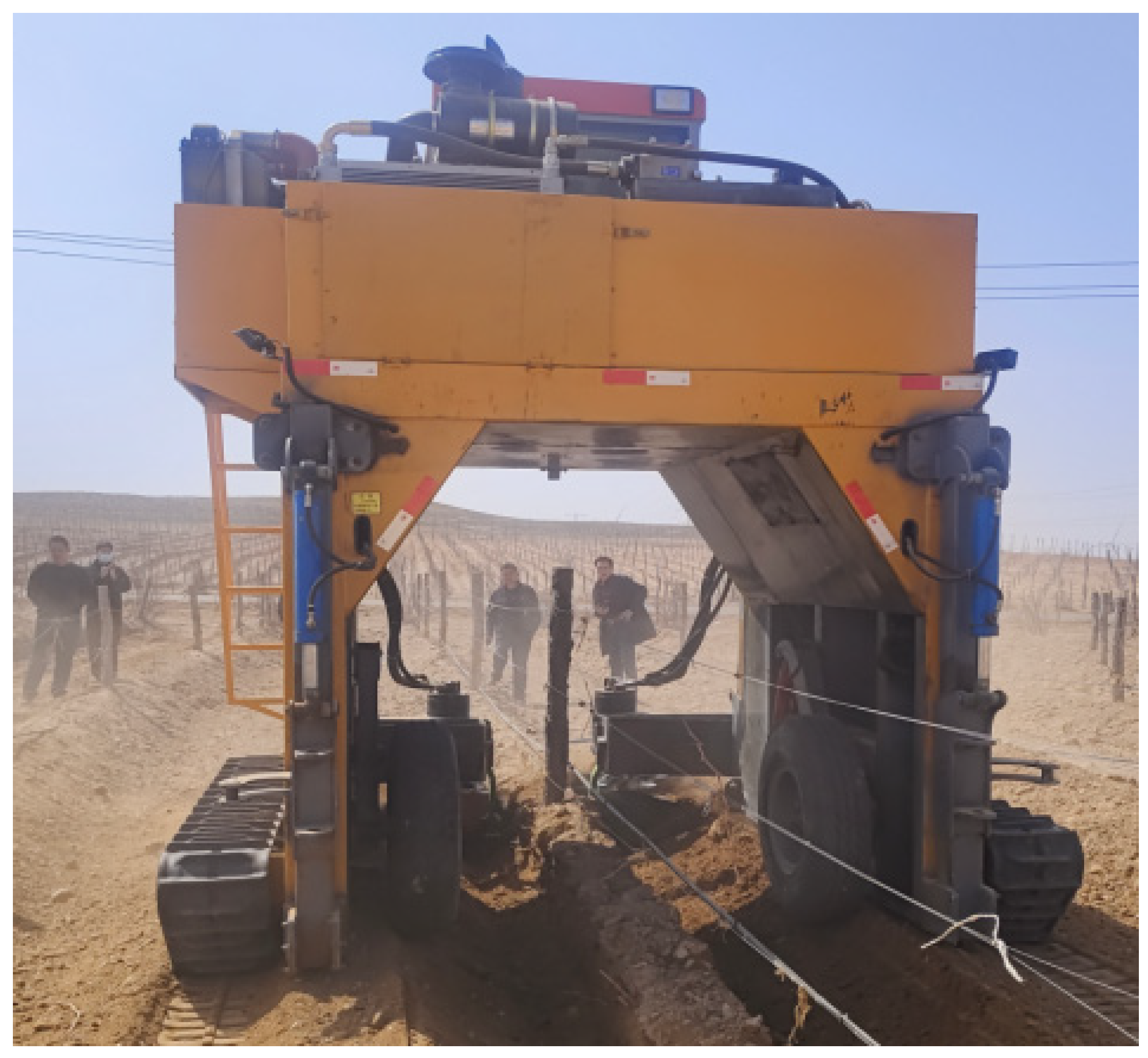
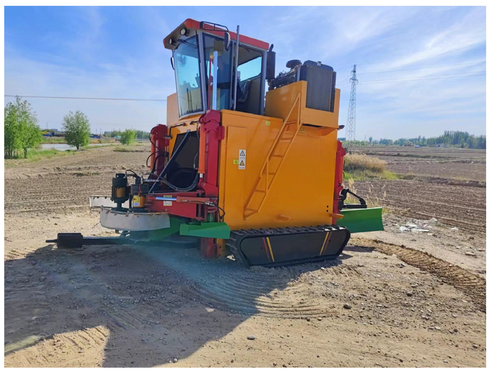
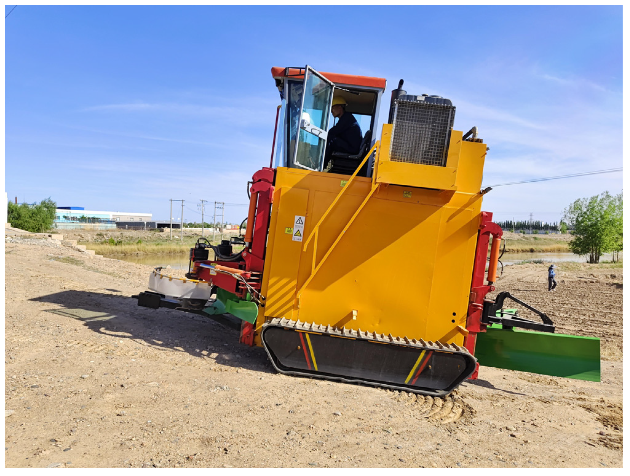
2.2. Structure and Working Principle of the Whole Machine
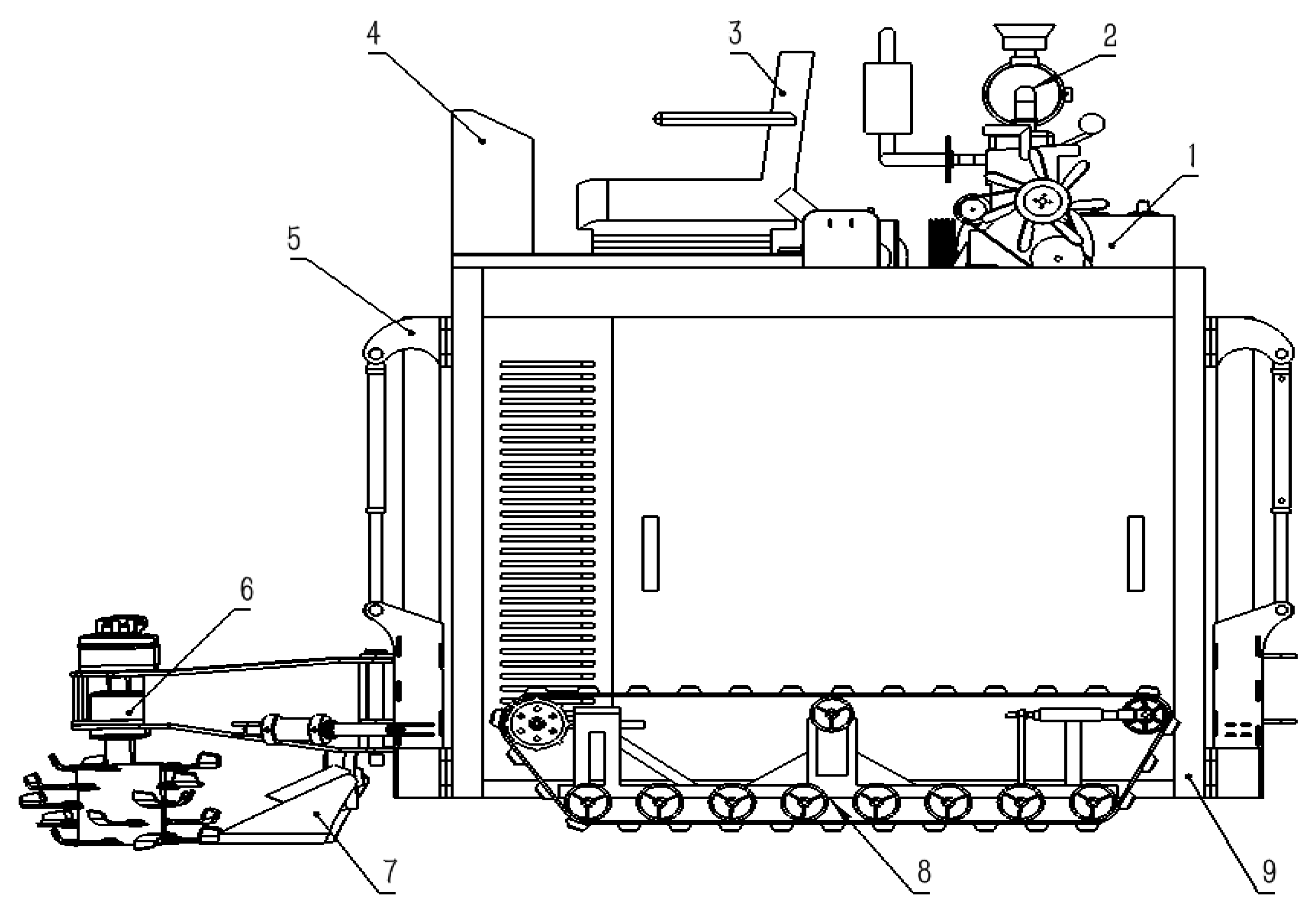
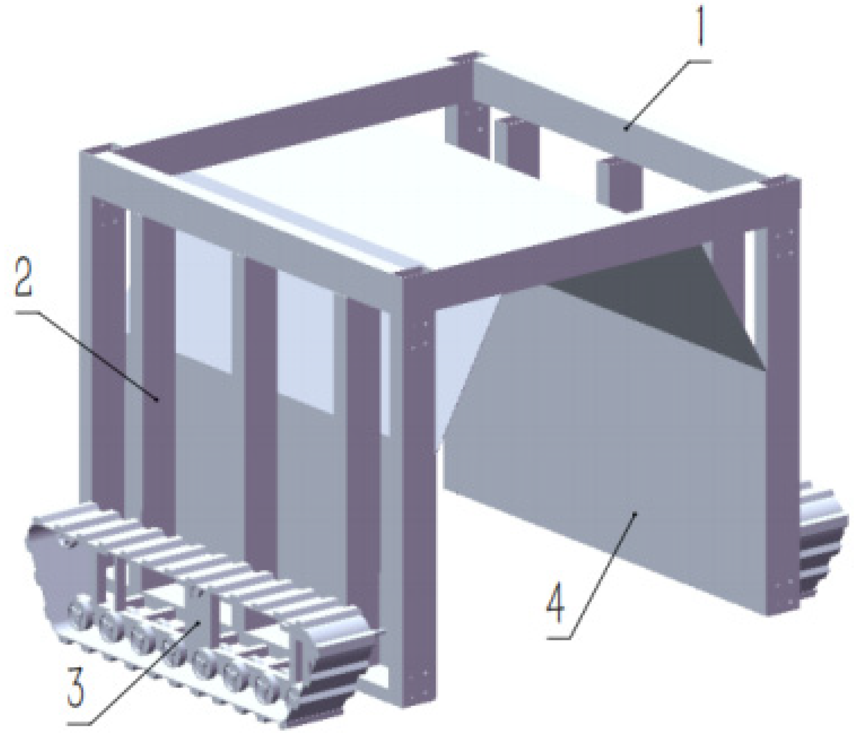
2.2.1. Overall Structure
2.2.2. Chassis Working Principle
2.3. Design of Walking Device
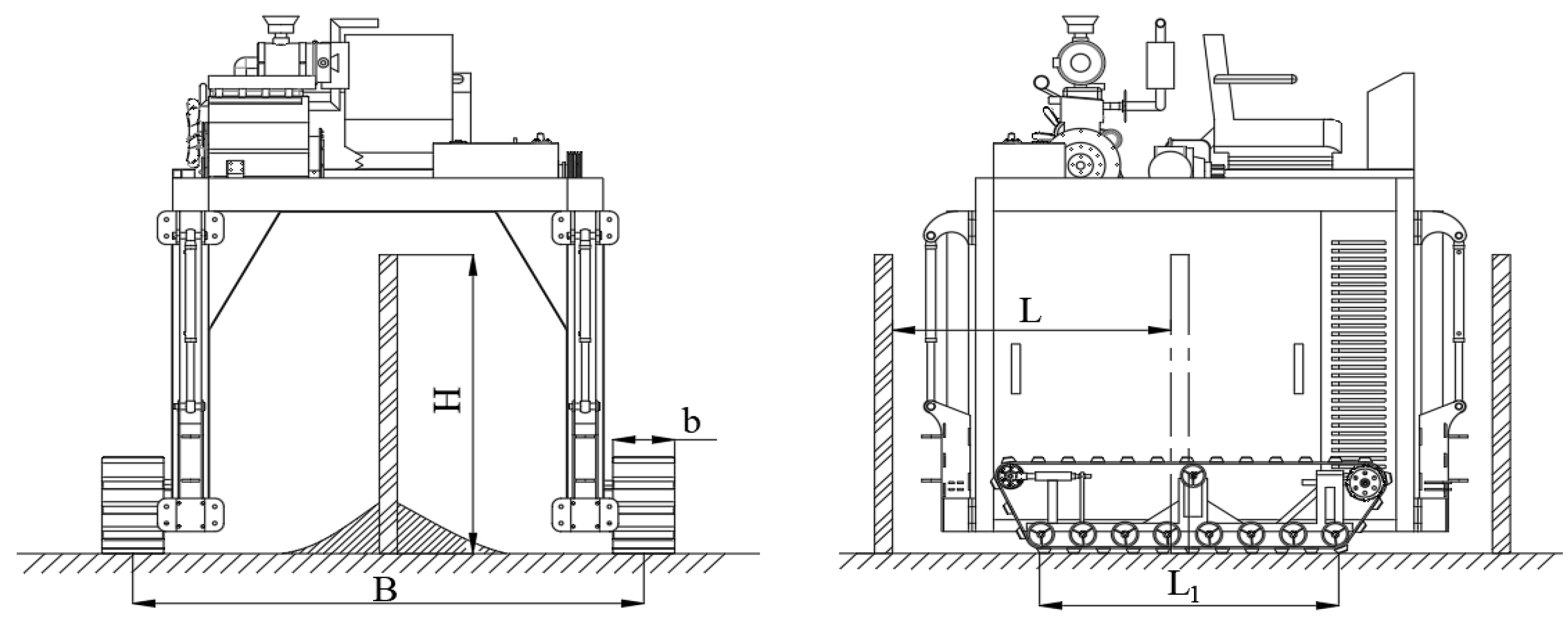
2.3.1. Analysis of Operational Walking Environment
2.3.2. Calculation of Main Parameters for the Walking Device
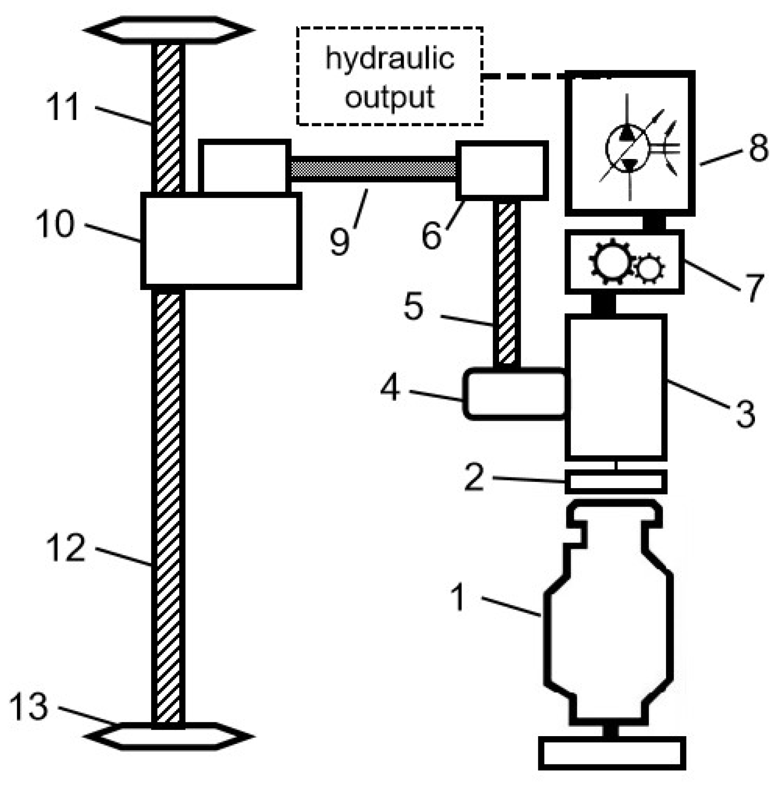
2.4. Design and Calculation of Drive System
2.4.1. Design of Drive Scheme
2.4.2. Hydraulic System Principle
2.4.3. Steering Performance Analysis
2.4.4. Engine Calculation and Selection
2.4.5. Selection and Calculation of the Transmission
2.5. Design of Hanging Lifting Mechanism
2.6. Chassis Structure Design
3. Results and Discussion
3.1. Whole Machine Stability Analysis
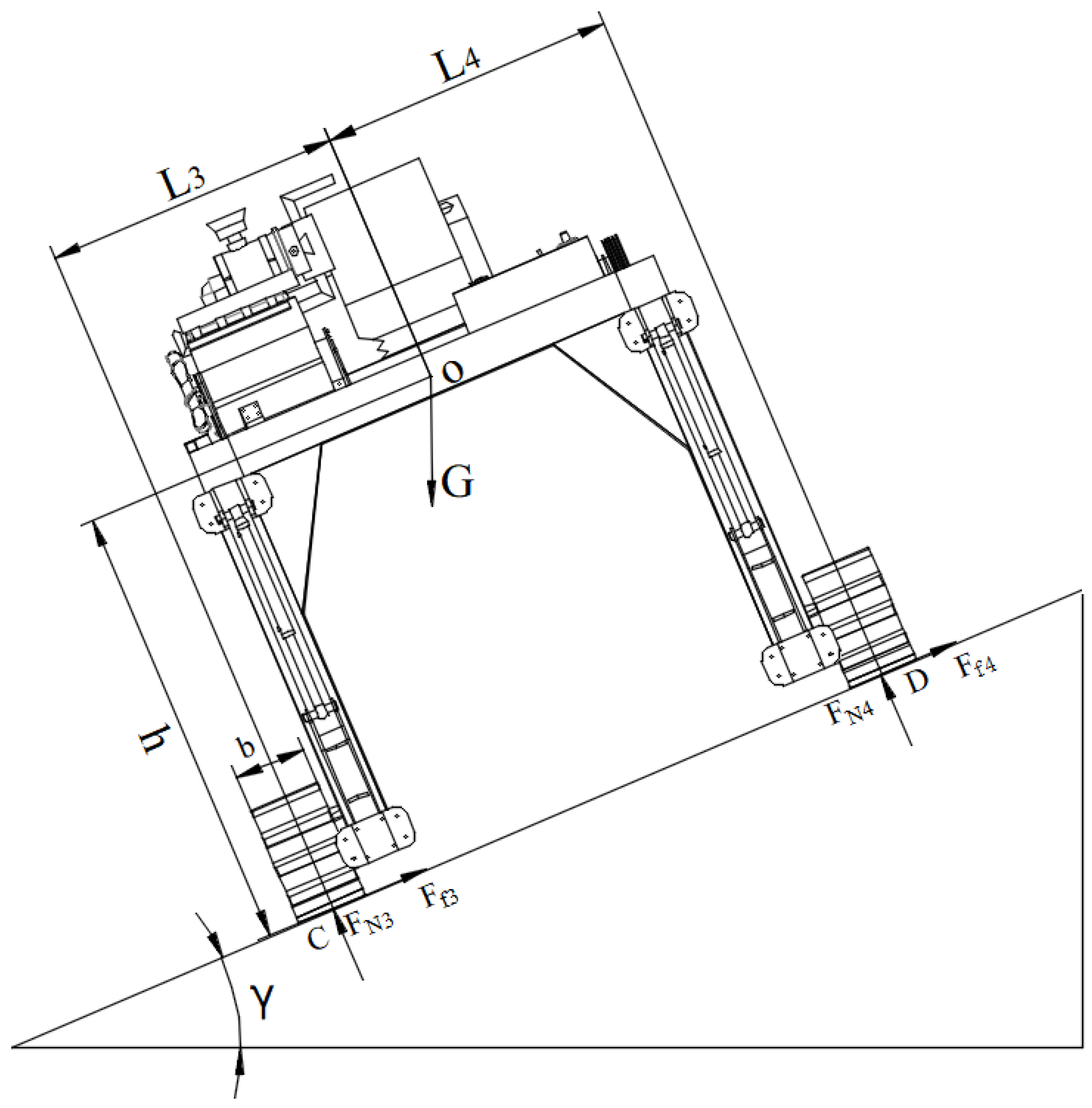
3.1.1. Longitudinal Driving Stability Analysis
3.1.2. Lateral Driving Stability Analysis
3.2. Field Test
3.2.1. Maximum Driving Speed Test
3.2.2. Minimum Turning Radius Test
3.2.3. Longitudinal Driving Stability
3.2.4. Lateral Driving Stability
3.2.5. Hitch Lifting Capacity
4. Conclusions
- (1)
- For the cultivation of wine grapes using a vertical trellis system, traditional operations powered by tractors often result in a wide range of equipment types and low efficiency. To address this issue, a multifunctional operation platform based on a gantry mechanical structure has been developed. This involved the design and calculation of key components, and a prototype was trial-manufactured. The equipment is capable of performing bilateral operations simultaneously, achieving twice the efficiency of traditional machinery. With the development of additional operational components, this platform not only boosts efficiency but also reduces the mechanical investment costs for grape growers.
- (2)
- The power from the diesel engine is transmitted using a transfer case combined with a power take-off unit. The walking device uses a track system with a track width of 379 mm, a track support surface length of 2.4 m, and a track gauge of 2.8 m, providing good ground pressure distribution without causing secondary soil compaction. Considering that frost protection and soil clearing operations are the most power-consuming tasks, the total power requirement for the machine was determined to be 141 kW. A 6-speed gearbox was selected based on calculations to meet the speed requirements for different operational stages.
- (3)
- Field performance tests showed that the gantry track-mounted self-propelled wine grape operations platform has a maximum traveling speed of 3.85 km/h, a minimum turning radius of 3.95 m, a maximum longitudinal climbing angle of 18°, and a maximum lateral angle of 26°. The average settlement of the heaviest operational component over 30 min was 1.58 mm, with lifting height stability reaching 99.7%, thus meeting the requirements for field operations.
Author Contributions
Funding
Institutional Review Board Statement
Data Availability Statement
Acknowledgments
Conflicts of Interest
References
- Liu, Y.; Liu, Y.Y.; Chen, J.C.; Li, J.; Lin, X.; Lin, G. Research status and trend of key technologies of standardized orchard multi-functional operation platform. J. Intell. Agric. Mech. 2024, 5, 31–39. [Google Scholar] [CrossRef]
- Yang, T.; Sun, F.C.; Huang, B.; Wu, B.; Ran, G. Research progress on key technologies of orchard operating platform. J. Chin. Agric. Mech. 2024, 45, 152–159. [Google Scholar] [CrossRef]
- Wang, W.W.; Chen, L.Q.; Yang, Y.; Liu, L. Development and Prospect of Agricultural Machinery Chassis Technology. Trans. Chin. Soc. Agric. Mach. 2021, 52, 1–15. [Google Scholar] [CrossRef]
- Ji, W.W. Structural Design and Experimental Study of Chassis of High Gap Planter; Hunan Agricultural University: Changsha, China, 2020. [Google Scholar] [CrossRef]
- Xu, X.J. Design of Chassis Traveling System of High-ClearanceTea Garden Management Crawler; Jiangsu University: Zhenjiang, China, 2016. [Google Scholar] [CrossRef]
- Wu, Y. Multifunctional Grape Working Machine Dedicated Chassis Design; Ningxia University: Ningxia, China, 2016. [Google Scholar] [CrossRef]
- Fu, Y.Y. Type Selection, Design and Calculation of Walking Mechanism of Rubber Crawler Chassis. Intern. Combust. Engine Parts 2022, 13, 26–28. [Google Scholar] [CrossRef]
- Cai, Y.C.; Gao, Q.M.; Luo, Y.Y.; Mi, Z.; Li, Z.; Lv, P. Design and testing of a small tracked powered chassis for hilly mountainous terrain. J. Guangxi Univ. Sci. Technol. 2024, 3. Available online: http://kns.cnki.net/kcms/detail/45.1395.T.20240411.0851.015.html (accessed on 12 April 2024).
- Gao, Q.; Pan, D.; Zhang, X.; Deng, F.; Huang, D.; Wang, L.; Wang, L. Design and Simulation of Entire Track Modular Unmanned Agricultural Power Chassis. Trans. Chin. Soc. Agric. Mach. 2020, 51, 561–570. [Google Scholar] [CrossRef]
- Chen, A.C.; Mu, X.H.; Du, F.P.; Guo, H. Design of Small Tracked Vehicle Power Transmission System. Machinery 2013, 42, 11–13. [Google Scholar] [CrossRef]
- Wang, M.; Zhao, B.; Wang, C.W.; Li, H.; Liu, Y.; Fang, X. Method for Controlling Turning Radius of Crawler-type Tractors Based on GMlM. Trans. Chin. Soc. Agric. Mach. 2020, 51, 557–563. [Google Scholar] [CrossRef]
- Liu, W.J.; Luo, X.W.; Zeng, S.; Wen, Z.; Zeng, L. Field turning mechanism and performance test ofcrawler reclaimed rice harvester. J. Jilin Univ. 2023, 53, 2695–2705. [Google Scholar] [CrossRef]
- Gao, X.; Guo, J.; Zhu, Z.; Han, S. Design of Power Transmission System of High-clearance Self-propelled Sprayer. J. Agric. Mech. Res. 2017, 39, 247–251, 268. [Google Scholar] [CrossRef]
- Ali, M.; Islam, M.N.; Reza, M.N.; Hong, J.G.; Gulandaz, M.A.; Chung, S.O. Analysis of power requirement of a small-sized tracked-tractor during agricultural field operations. IOP Conf. Ser. Earth Environ. Sci. 2021, 924, 012017. [Google Scholar] [CrossRef]
- Cheng, D.X. Hand Book of Mechanical Design; Chemical Industry Press: Beijing, China, 2004. [Google Scholar]
- Wei, H.; Wang, D.; Lian, W.; Shao, S.; Yang, X.; Huang, X. Development of 4UFD-1400 type potato combine harvester. Trans. Chin. Soc. Agric. Eng. 2013, 29, 11–17. [Google Scholar] [CrossRef]
- Du, X.Q.; Ning, C.; He, L.Y.; Qian, Y.; Zhang, G.F.; Yao, X.H. Design and Test of Crawler-type High Clearance Camellia oleifera Fruit Vibratory Harvester. Trans. Chin. Soc. Agric. Mach. 2021, 52, 1–15. [Google Scholar] [CrossRef]
- Wan, X.Y.; Shu, C.X.; Liao, Q.X.; Fan, W.; Zhou, Q.; Liao, Y. Design and Experiment of Self-propelled Middle-placement RapeWindrower with High Ground Elearance Crawler. Trans. Chin. Soc. Agric. Mach. 2022, 53, 109–121. [Google Scholar] [CrossRef]
- Watanabe, M.; Sakai, K. Novel power hop model for an agricultural tractor with coupling bouncing, stick-slip, and free-play dynamics. Biosyst. Eng. 2021, 204, 156–169. [Google Scholar] [CrossRef]
- He, Z.; Song, Z.; Wang, L.; Zhou, X.; Gao, J.; Wang, K.; Yang, M.; Li, Z. Fasting the stabilization response for prevention of tractor rollover using active steering: Controller parameter optimization and real-vehicle dynamic tests. Comput. Electron. Agric. 2023, 204, 107525. [Google Scholar] [CrossRef]
- Petrović, D.V.; Cerović, V.B.; Radojević, R.L.; Mileusnić, Z.I. An approach to characterization of the agricultural self-propelled machines stability. J. Terramech. 2021, 93, 51–63. [Google Scholar] [CrossRef]
- Li, J.L.; Lu, Z.Q.; Bao, Y.D.; Yang, F.; Li, Y. Mechanism Optimization Design of Crawler Weeding Robot with High Clearance Moving Platform. Agric. Technol. Equip. 2022, 22–26. [Google Scholar] [CrossRef]
- Qing, Z.Y.; Huang, L.; Fan, Y.; Ren, Z. Design and Climbing Kinematics Simulation of Crawler Agricultural achinery. Farm Mach. Using Maint. 2022, 1–5, 10. [Google Scholar] [CrossRef]


| Parameter | Numerical Value/Form |
|---|---|
| Travel mechanism | Caterpillar type |
| Whole structure | Gantry cross-type |
| Gearbox form | Mechanical transmission |
| Engine type | Diesel engine |
| Minimum speed/(km/h) | 1 |
| Maximum climbing angle/° | ≥10° |
| Inner span width/(m) | 2.2 |
| Inner span height/(m) | 2 |
| Name | Numerical Value | |||||
|---|---|---|---|---|---|---|
| Gear | 1 | 2 | 3 | 4 | 5 | 6 |
| Transmission ratio | 5.7 | 4.2 | 3.3 | 2.7 | 2.2 | 1 |
| Fast C6J76TA | 5.7 | 3.5 | 2.3 | 1.45 | 1 | 0.8 |
| Theoretical velocity (km/h) | 1 | 1.3 | 1.7 | 2.1 | 2.6 | 4 |
| Gear | Time of Use (Min) | Theoretical Velocity (km/h) | Actual Velocity (km/h) | Percentage of Consolidation of Deviation |
|---|---|---|---|---|
| Gear 1 | 8.8 | 1 | 0.68 | 32% |
| Gear 2 | 6.4 | 1.3 | 0.94 | 27.69% |
| Gear 3 | 4.2 | 1.7 | 1.42 | 16.74% |
| Gear 4 | 3.2 | 2.1 | 1.83 | 12.86% |
| Gear 5 | 2.8 | 2.6 | 2.12 | 18.46% |
| Gear 6 | 1.5 | 4 | 3.85 | 3.75% |
| Diversion | Angle | Testing Radius (m) | Mean Value (m) | Minimum Turning Radius (m) |
|---|---|---|---|---|
| Levoversion | 120° | 3.8 | 3.9 | 3.95 |
| 240° | 4.0 | |||
| 360° | 3.9 | |||
| Dextroversion | 120° | 3.9 | 4.0 | |
| 240° | 4.1 | |||
| 360° | 4.0 |
| Gradient | Passing Distance (mm) | Left Track Ground Clearance (mm) | Right Track Ground Clearance (mm) |
|---|---|---|---|
| 5° | 10 | 0 | 0 |
| 10° | 10 | 0 | 0 |
| 13° | 10 | 0 | 0 |
| 18° | 10 | 1.5 | 0 |
| 19° | 3 | 3 | 5 |
| Gradient | Passing Distance (mm) | Low Side Track Clearance (mm) | The High Side of the Track Has Ground Clearance (mm) |
|---|---|---|---|
| 20° | 10 | 0 | 0 |
| 22° | 10 | 0 | 0 |
| 24° | 10 | 0 | 0 |
| 26° | 10 | 0 | 0 |
| 28° | 2 | 0 | 2 |
| Improve the Quality (kg) | Cylinder Stroke (mm) | 10 Min Height Change (mm) | 20 Min Height Change (mm) | 30 Min Height Change (mm) | Total Settlement Change (mm) | Average Settlement (mm) |
|---|---|---|---|---|---|---|
| 558 | 0 | 0 | 0 | 0 | 0 | 1.58 |
| 150 | 0 | 0.5 | 1 | 1.5 | ||
| 250 | 0 | 0.8 | 1.2 | 2 | ||
| 350 | 0 | 0.6 | 0.8 | 1.4 | ||
| 450 | 0.1 | 0.7 | 1.1 | 1.9 | ||
| 550 | 0.3 | 1 | 1.4 | 2.7 |
Disclaimer/Publisher’s Note: The statements, opinions and data contained in all publications are solely those of the individual author(s) and contributor(s) and not of MDPI and/or the editor(s). MDPI and/or the editor(s) disclaim responsibility for any injury to people or property resulting from any ideas, methods, instructions or products referred to in the content. |
© 2024 by the authors. Licensee MDPI, Basel, Switzerland. This article is an open access article distributed under the terms and conditions of the Creative Commons Attribution (CC BY) license (https://creativecommons.org/licenses/by/4.0/).
Share and Cite
Li, X.; Yang, F.; Sun, R.; Peng, Z.; Shen, X.; Xu, G. Design of a Gantry Crawler Multifunctional Operation Platform for Wine Grape Cultivation. Agriculture 2024, 14, 1587. https://doi.org/10.3390/agriculture14091587
Li X, Yang F, Sun R, Peng Z, Shen X, Xu G. Design of a Gantry Crawler Multifunctional Operation Platform for Wine Grape Cultivation. Agriculture. 2024; 14(9):1587. https://doi.org/10.3390/agriculture14091587
Chicago/Turabian StyleLi, Xiang, Fazhan Yang, Ruijun Sun, Zehui Peng, Xitong Shen, and Guoli Xu. 2024. "Design of a Gantry Crawler Multifunctional Operation Platform for Wine Grape Cultivation" Agriculture 14, no. 9: 1587. https://doi.org/10.3390/agriculture14091587
APA StyleLi, X., Yang, F., Sun, R., Peng, Z., Shen, X., & Xu, G. (2024). Design of a Gantry Crawler Multifunctional Operation Platform for Wine Grape Cultivation. Agriculture, 14(9), 1587. https://doi.org/10.3390/agriculture14091587