
Dynamic Measurement Method for Steering Wheel Angle of Autonomous Agricultural Vehicles

Abstract
:1. Introduction
Literature Review
2. Method
2.1. Non-Contact Measurement Principle of Steering Wheel Angle Based on Attitude Sensor
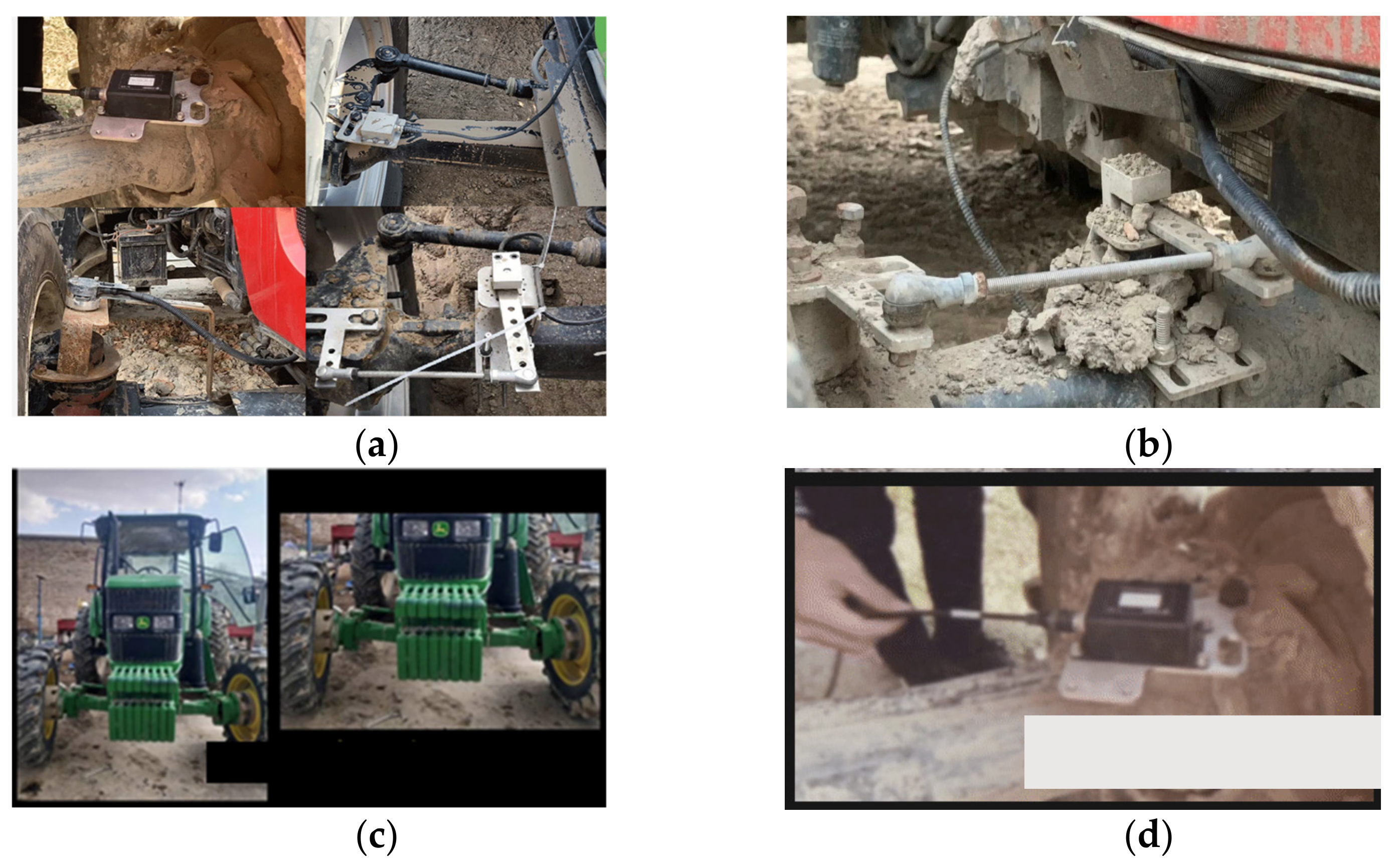
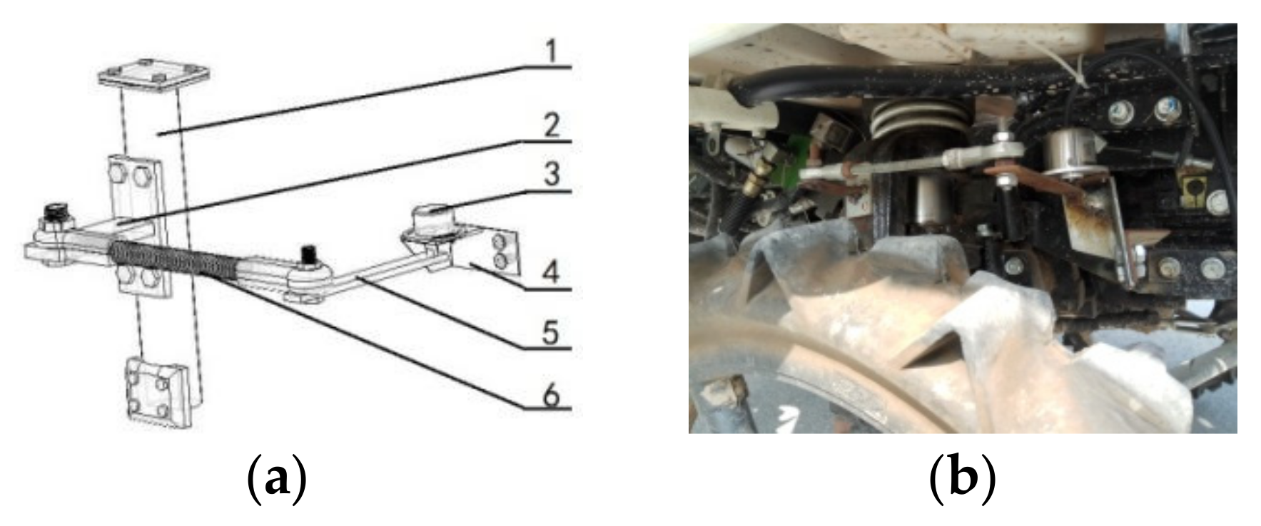
2.2. Installation of Non-Contact Sensor
2.3. Angle Measurement Principle
3. Analysis and Optimization Method of Zero Position Error for Steering Wheel Angle
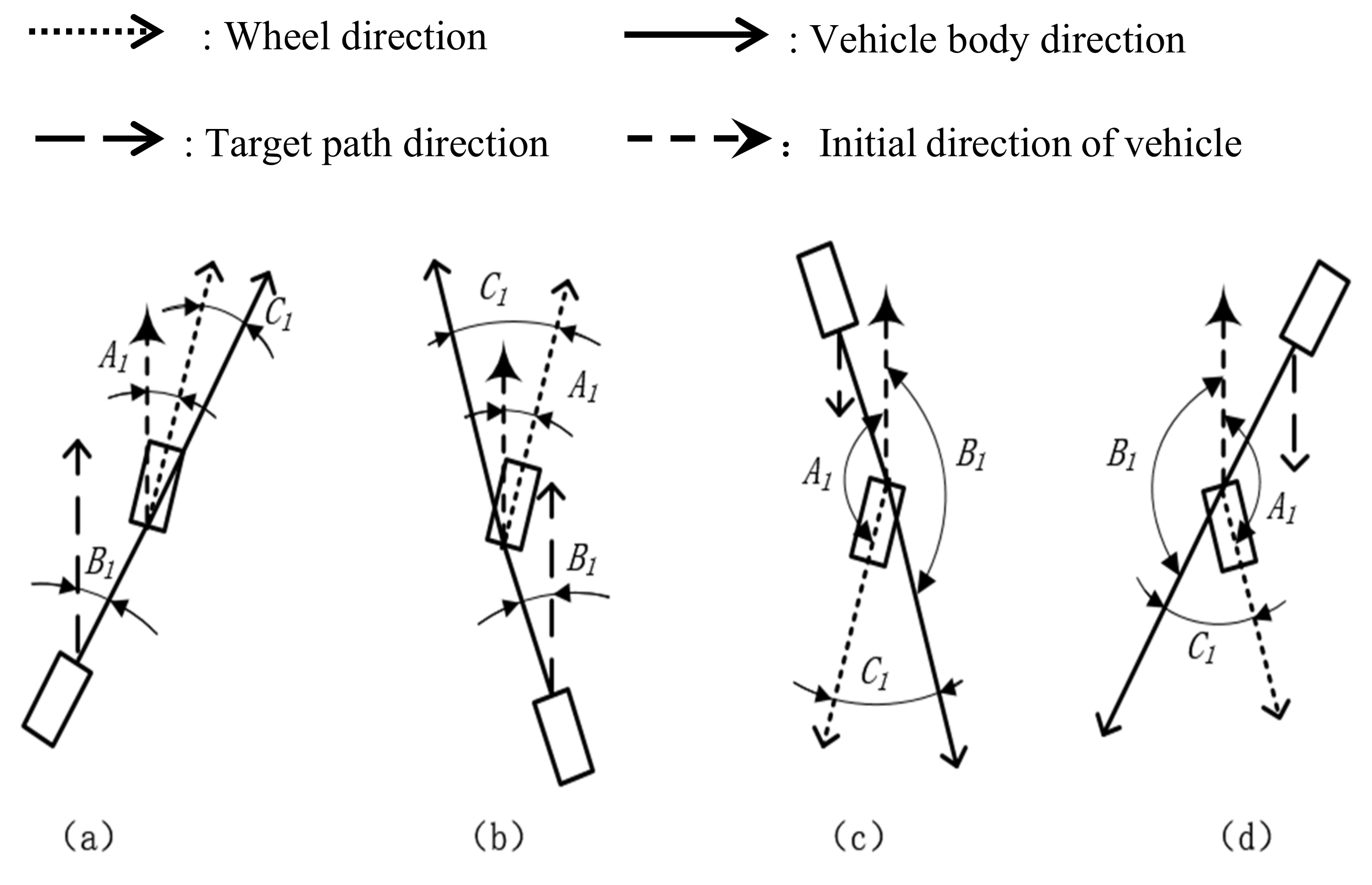
3.1. Error Analysis of Steering Wheel Angle
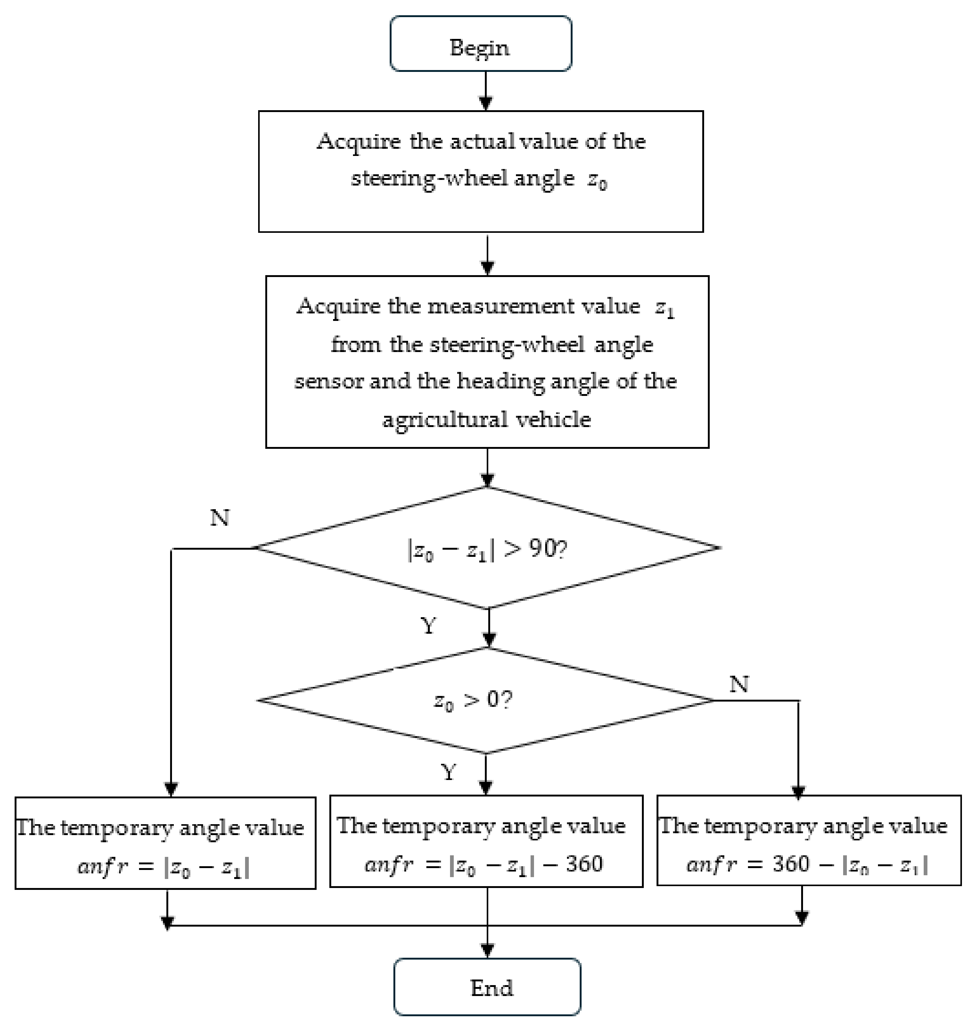
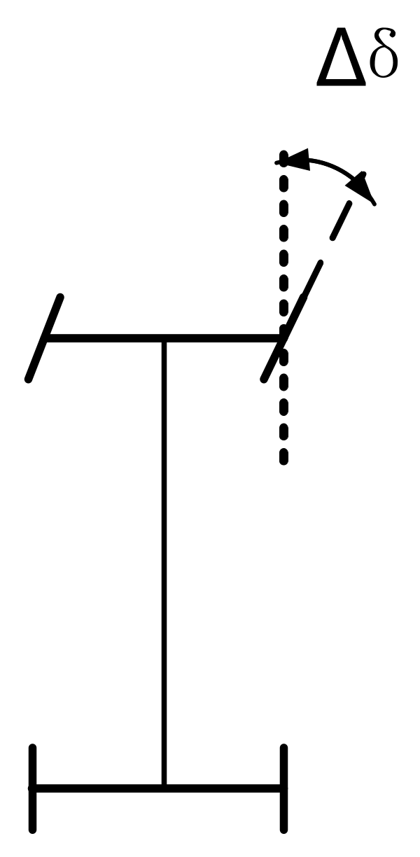
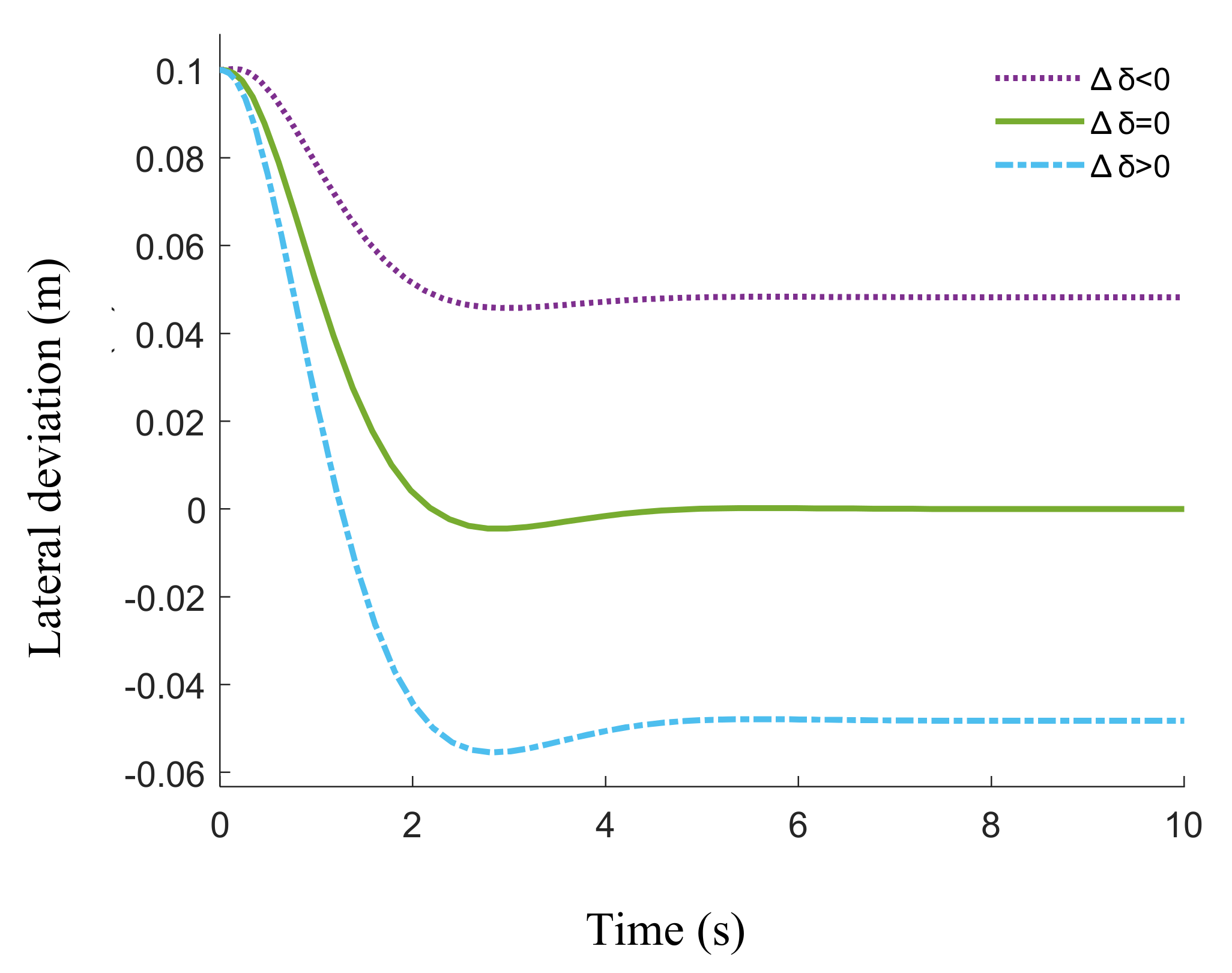
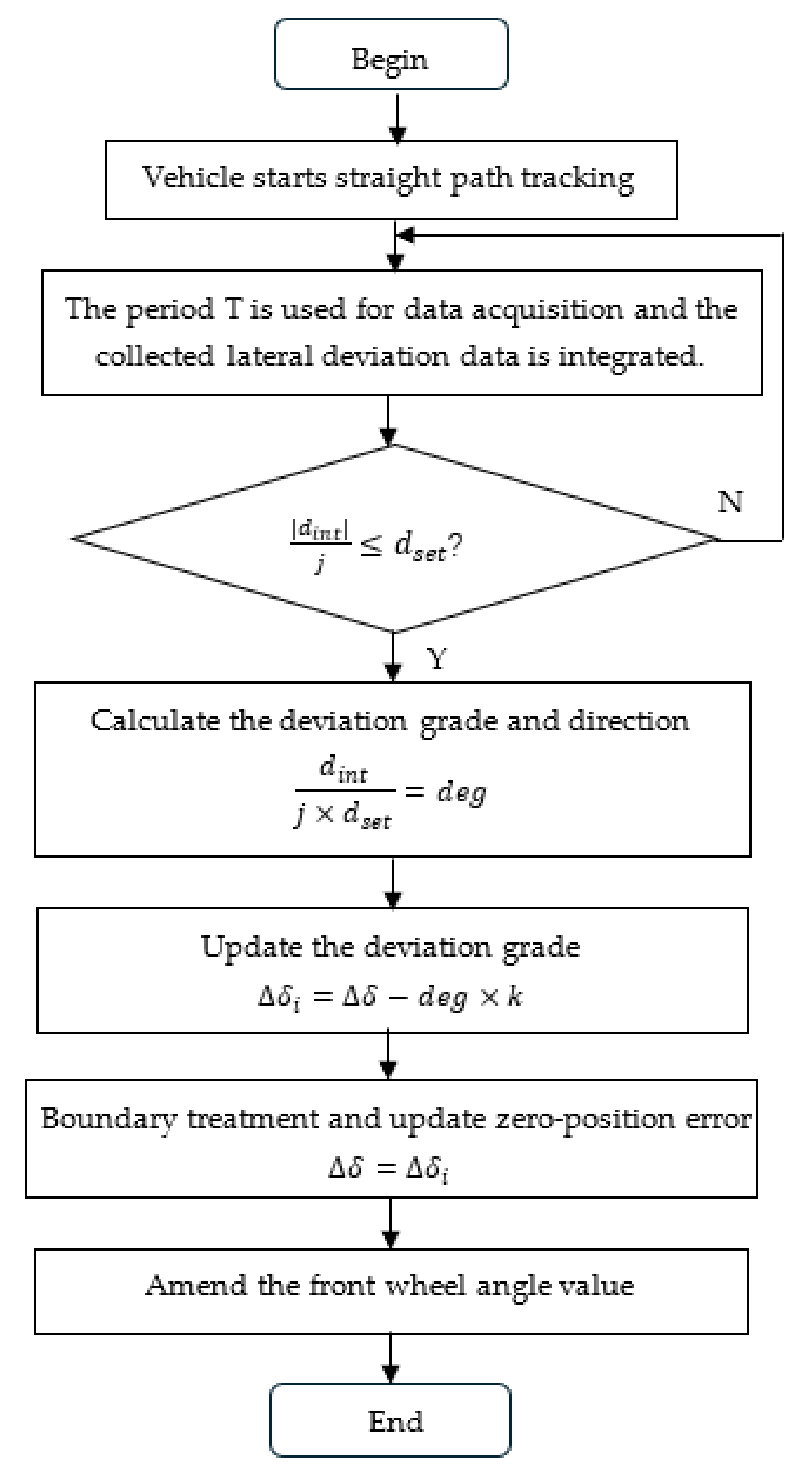
3.2. Optimization Method of Zero Position Error
4. Results and Discussion
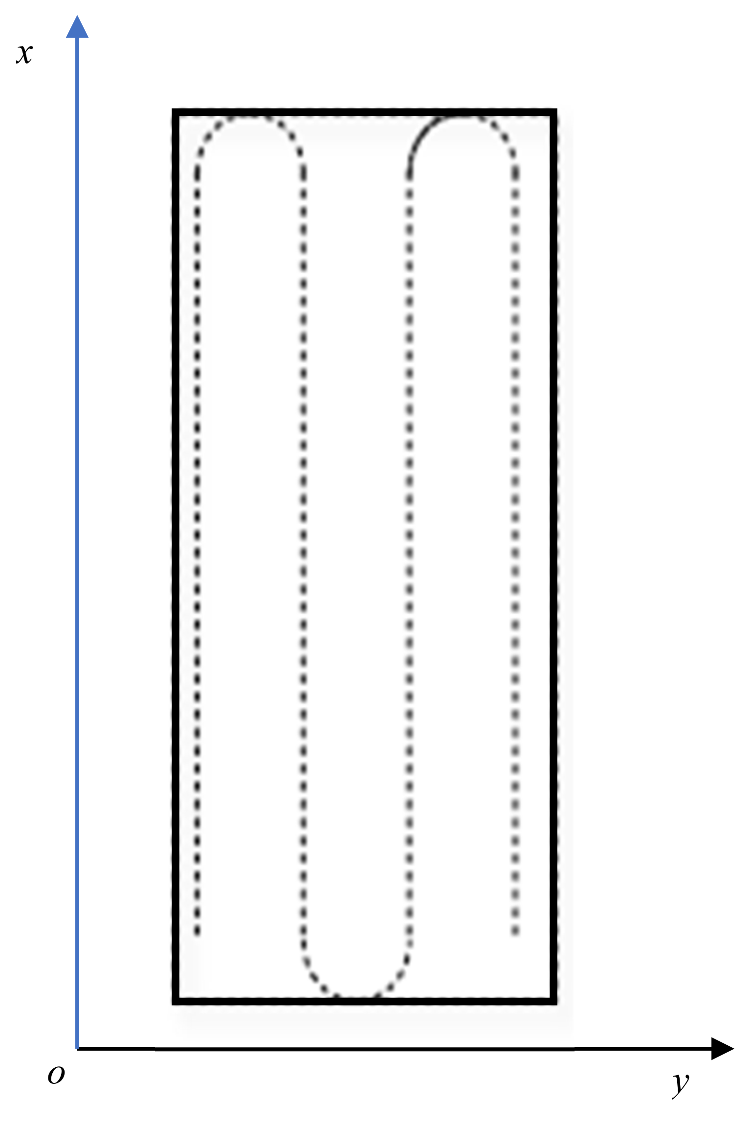
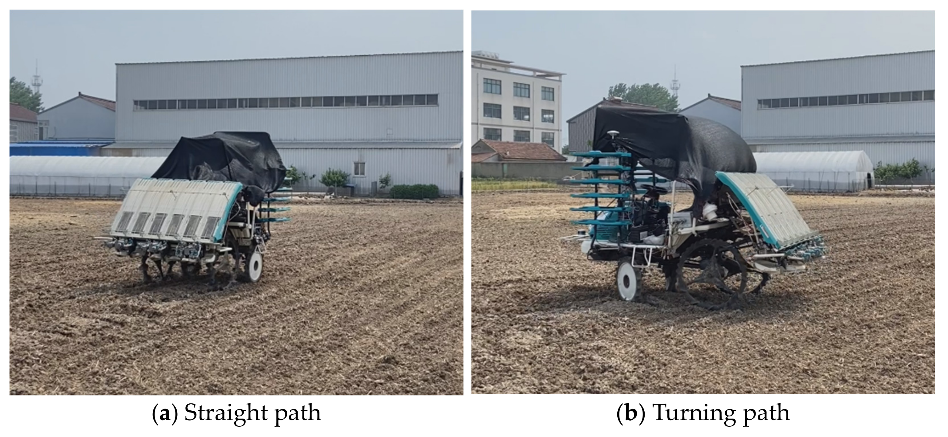
4.1. Test Platform
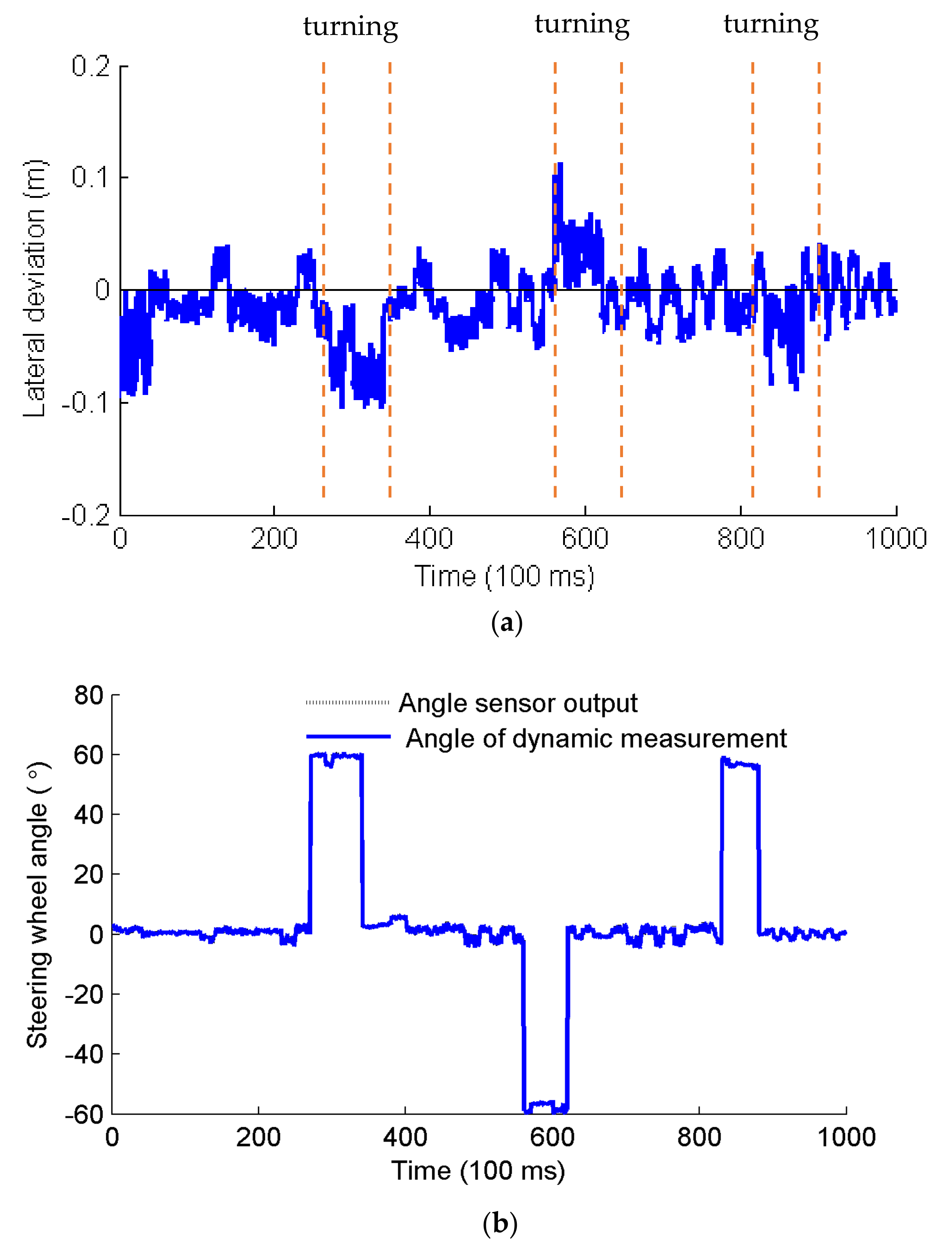
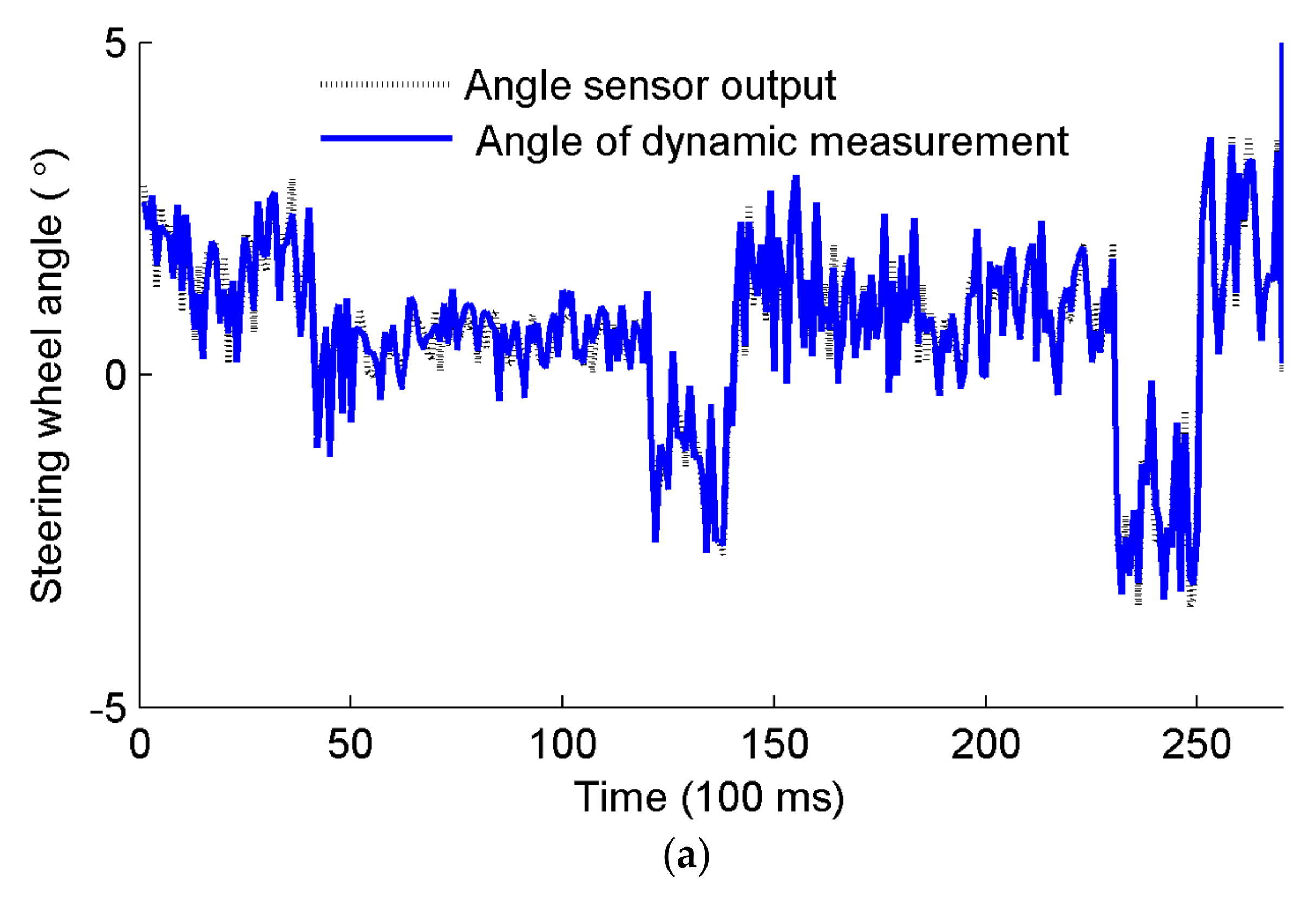
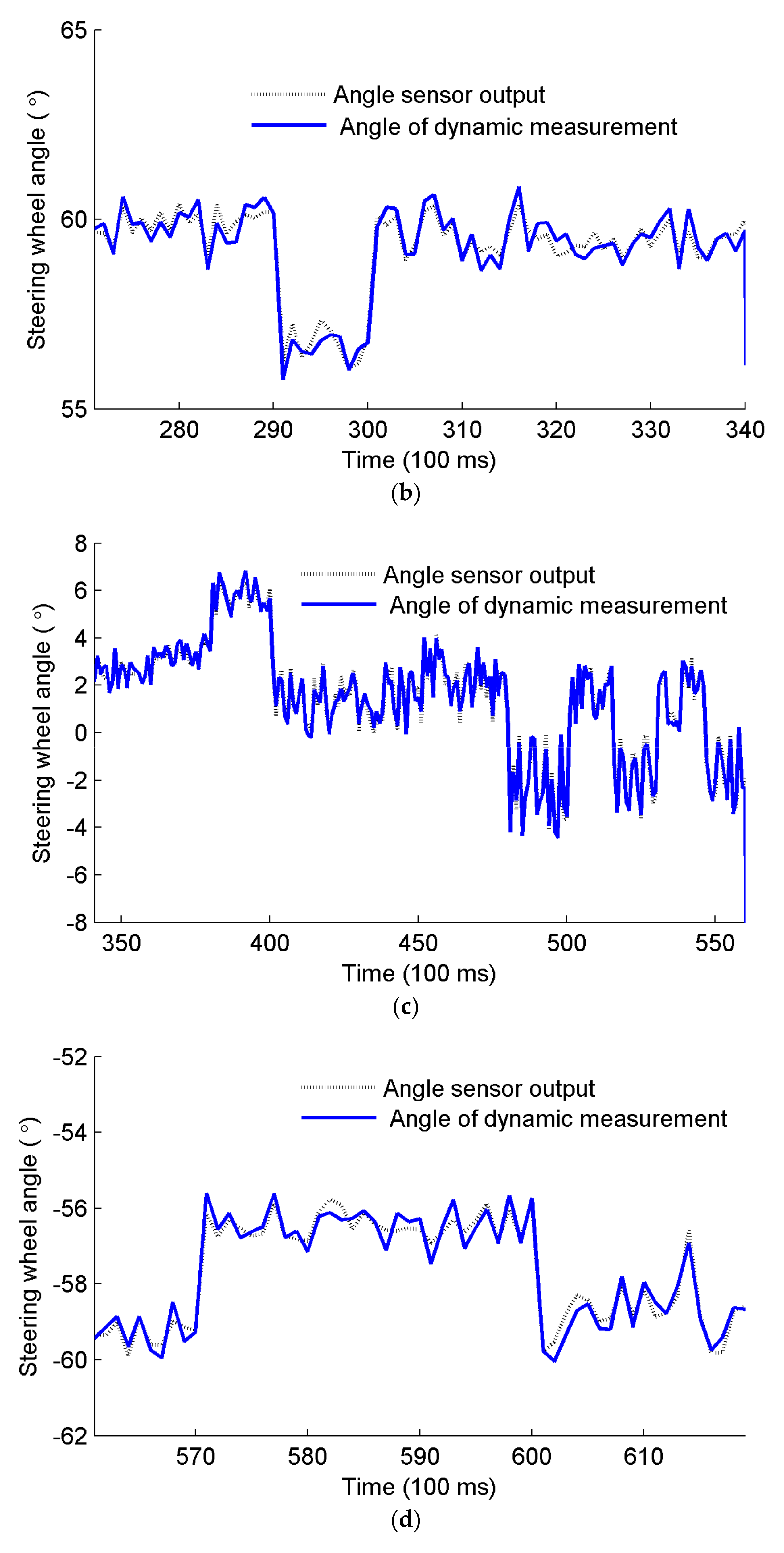
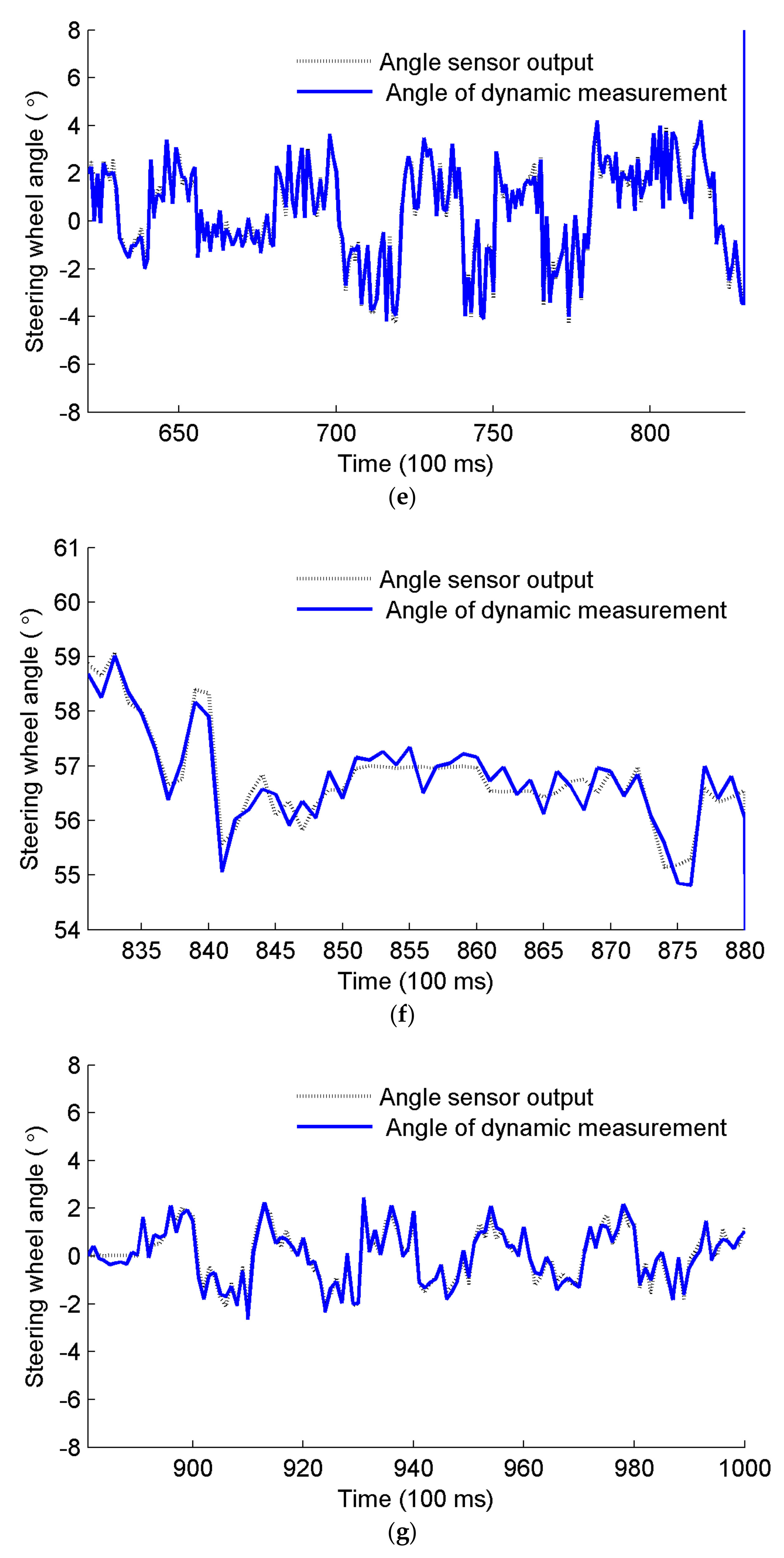
4.2. Results
4.3. Discussion
5. Conclusions
Author Contributions
Funding
Institutional Review Board Statement
Informed Consent Statement
Data Availability Statement
Conflicts of Interest
References
- Wang, A.C.; Zhang, W.; Wei, X.H. A review on weed detection using ground-based machine vision and image processing techniques. Comput. Electron. Agric. 2019, 158, 226–240. [Google Scholar] [CrossRef]
- Li, M.; Imou, K.; Wakabayashi, K.; Yokoyama, S. Review of research on agricultural vehicles autonomous guidance. Int. J. Biol. ENG 2009, 2, 1–16. [Google Scholar]
- Zhou, J.; He, Y.Q. Research progress on navigation path planning of agricultural machinery. Trans. Chin. Soc. Agric. Mach. 2021, 52, 1–14. (In Chinese) [Google Scholar]
- Huang, W.Y.; Ji, X.; Wang, A.Z.; Wang, Y.F.; Wei, X.H. Straight-line path tracking control of agricultural tractor-trailer based on fuzzy sliding mode control. Appl. Sci.-Base 2023, 13, 872. [Google Scholar] [CrossRef]
- Zhang, Z.G.; Huang, H.X.; Luo, X.W.; Zhang, G.C.; Zhang, W.Y.; Peng, M.D.; Liu, W.L. Steering control system for a tractor using electric steering wheel. Trans. Chin. Soc. Agric. Mach. 2024, 40, 48–57. [Google Scholar]
- Ji, X.; Wei, X.H.; Wang, A.Z.; Cui, B.B.; Song, Q. A novel composite adaptive terminal sliding mode controller for farm vehicles lateral path tracking control. Nonlinear Dyn. 2022, 10, 2415–2428. [Google Scholar] [CrossRef]
- Ma, Z.H.; Yin, C.; Du, X.Q.; Zhao, L.J.; Lin, L.P.; Zhang, G.F.; Wu, C.Y. Rice row tracking control of crawler tractor based on the satellite and visual integrated navigation. Comput. Electron. Agric. 2022, 197, 106935. [Google Scholar] [CrossRef]
- Lim, J.H.; Choi, K.H.; Cho, J.; Lee, H.K. Integration of GPS and monocular vision for land vehicle navigation in urban area. Int. J. Automot. Technol. 2017, 18, 345–356. [Google Scholar] [CrossRef]
- Cui, B.B.; Zhang, J.X.; Wei, X.H.; Cui, X.Y.; Sun, Z.Y.; Zhao, Y.; Liu, Y.F. Improved information fusion for agricultural machinery navigation based on context-constrained Kalman filter and dual-antenna RTK. Actuators 2024, 13, 160. [Google Scholar] [CrossRef]
- Xie, B.; Jin, Y.C.; Faheem, M.; Gao, W.J.; Liu, J.Z.; Jiang, H.K.; Cai, L.J.; Li, Y.X. Research progress of autonomous navigation technology for multi-agricultural scenes. Comput. Electron. Agric. 2023, 211, 107963. [Google Scholar] [CrossRef]
- Lan, Y.B.; Zhao, D.N.; Zhang, Y.F.; Zhu, J.K. Exploration and development prospect of eco-unmanned farm modes. Trans. Chin. Soc. Agric. Mach. 2021, 37, 312–327. [Google Scholar]
- Chen, T.T.; Xu, L.Z.; Ahn, H.S.; Lu, E.; Liu, Y.B.; Xu, R.J. Evaluation of headland turning types of adjacent parallel paths for combine harvesters. Biosyst. Eng. 2023, 233, 93–113. [Google Scholar] [CrossRef]
- Hu, S.P.; Shang, Y.H.; Liu, H. Comparative test between displacement and four-bar indirect measurement methods for tractor guide wheel angle. Trans. Chin. Soc. Agric. Mach. 2017, 33, 76–82. [Google Scholar]
- Miao, C.X.; Chu, H.X.; Gao, J.J.; Sun, Z.H.; Yi, R.R. Steering angle adaptive estimation system based on GNSS and MEMS gyro. Comput. Electron. Agric. 2018, 153, 196–201. [Google Scholar] [CrossRef]
- Yin, X.; Du, J.; Noguchi, N.; Yang, T.X.; Jin, C.Q. Development of autonomous navigation system for rice transplanter. Int. J. Agric. Biol. Eng. 2018, 11, 89–94. [Google Scholar] [CrossRef]
- Li, J.Y.; Shang, Z.J.; Li, R.F.; Cui, B.B. Adaptive sliding mode path tracking control of unmanned rice transplanter. Agriculture 2022, 12, 1225. [Google Scholar] [CrossRef]
- Li, J.Y.; Zhang, M.; Zhang, G.; Ge, D.Q.; Li, M.Q. Real-time monitoring system of seedling amount in seedling box based on machine vision. Agriculture 2023, 13, 371. [Google Scholar] [CrossRef]
- Miao, C.X.; Chu, H.X.; Sun, Z.H. Wheel turning angle measurement system based on double GNSS antennas and single Gyro. Trans. Chin. Soc. Agric. Mach. 2017, 48, 17–23. [Google Scholar]
- Xiao, M. A high-accuracy steering wheel angle sensor based on GMR. In Proceedings of the Sixth International Conference on Instrument & Measuremnet Computer Communication and Control, Harbin, China, 21–23 July 2016. [Google Scholar]
- Butt, M.A.; Riaz, F.; Khalid, S.; Abid, S.; Habib, M.A.; Shafique, S.; Han, K. Micro-electromechanical system based optimized steering angle estimation mechanism for customized self-driving vehicles. Meas. Control 2021, 54, 429–438. [Google Scholar] [CrossRef]
- Chen, Y.; He, Y. Development of agricultural machinery steering wheel angle measuring system based on GNSS attitude and motor encoder. Trans. Chin. Soc. Agric. Mach. 2021, 37, 10–17. [Google Scholar]
- Santana-Fernndez, J.; Gomez-Gil, J.; Del-Pozo-San-Cirilo, L. Design and implementation of a GPS guidance system for agricultural tractors using augmented technology. Sensors 2010, 10, 10435–10447. [Google Scholar] [CrossRef] [PubMed]
- Nagasaka, Y.; Umeda, N.; Kanetai, Y.; Taniwaki, K.; Sasaki, Y. Autonomous guidance for rice transplanting using global positioning and gyroscopes. Comput. Electron. Agric. 2004, 43, 223–234. [Google Scholar] [CrossRef]
- Lohan, S.K.; Narang, M.K.; Singh, M.; Singh, D.; Sidhu, H.S.; Singh, S.; Dixit, A.K.; Karkee, M. Design and development of remote-control system for two-wheel paddy transplanter. J. Field Robot. 2021, 39, 177–187. [Google Scholar] [CrossRef]
- Bayar, G.; Bergerman, M.; Koko, A.B.; Konukseven, E.I. Localization and control an autonomous orchard vehicle. Comput. Electron. Agric. 2015, 115, 118–128. [Google Scholar] [CrossRef]
- Yang, J.; Chang, T.N.; Hou, E. Lateral control for vehicle automatic steering with front sensor and GPS. In Proceedings of the International Conference on Control, Automation and Systems (ICCAS 2010), Gyeonggi-do, Republic of Korea, 27–30 October 2010; pp. 928–932. [Google Scholar]
- Groves, P.D. Navigation using inertial sensors. IEEE Aerosp. Electron. Syst. Mag. 2015, 2, 42–69. [Google Scholar] [CrossRef]


| Measurement Methods | Results or Accuracy | Advantage | Shortcoming | Reference |
|---|---|---|---|---|
| GNSS attitude and motor encoder | Standard deviation: 0.91°/2.56° (straight/curved path) | No complex mechanical structure | Depends on the kinematic model of the vehicle | [21] |
| GNSS and MEMS gyro | Average error: 0.06°/0.746° (straight/curved path) | No complex mechanical structure | Depends on the kinematic model of the vehicle | [18] |
| Two-gear wheel and rotary shaft-based mechanism | Mean error: 0.041°/0.083° (straight/curved path) | Complex mechanical structure | No dependence on the kinematic model of the vehicle | [20] |
| Absolute rotary encoder | Not given | Complex mechanical structure | No dependence on the kinematic model of the vehicle | [23] |
| A giant magnetoresistance sensor | Less than 1.5° | Complex mechanical structure | No dependence on the kinematic model of the vehicle | [19] |
| BeiDou and attitude sensor | Average absolute error: 0.057°/0.686° (straight/curved path) | No complex mechanical structure | No dependence on the kinematic model of the vehicle and the error equation of the steering wheel angle | This paper |
| Type | Parameter |
|---|---|
| Model | LPMS-IG1 RS232 |
| Communication mode | RS232 + USB |
| Size (mm) | 51 × 45 × 24 |
| Euler angle range | Roll: ±180°, Pitch: ±90°, Yaw: ±180° |
| Resolution | 0.01° |
| IP grade | IP67 |
| Supply voltage (V) | 5~36 VDC |
| Maximum transfer rate (Hz) | 500 |
| No. | Parameter Signature | Description |
|---|---|---|
| 1 | Autonomous rice transplanter | A six-row autonomous rice transplanter |
| 2 | Attitude sensor | Sensing steering angle variation of the front wheel |
| 3 | Navigation controller | Path planning, control algorithm executing, etc. |
| 4 | Vehicle-mounted controller | Controlling the vehicle to conduct path tracking and field operations based on the instructions from the navigation controller |
| 5 | Navigation mobile station | Conducting precise positioning and navigation of the vehicle by combining the information from the base station |
| 6 | Electric steering wheel | Steering the front wheel of the vehicle |
| 7 | Serial screen | Set parameters, display graphics and data |
| 8 | Data transmission module | Remote wireless transmission of data and control commands |
| 9 | Control algorithm | Pure pursuit algorithm |
| 10 | Combination navigation of BEIDOU and INS | Providing the navigation data such as position, velocity, Euler angle |
| 11 | Rotary angle sensor | Sensing the steering angle of the front wheel |
| 12 | Qt 5.14.2 | Development of navigation control software |
| 13 | Keil uVision 5.36.0.0 | Software development of vehicle-mounted controller |
| Type | Parameter |
|---|---|
| Model Rated voltage/V | DWQT-RS485-G 8–24 |
| Range/° | 0–360 |
| Output mode | RS485 |
| Accuracy/° Degree of linearity/FS Response frequency/Hz | 0.022 0.15%, 0.3% 1000 |
| Serial Number | Angle Sensor | Angle from the Proposed Measurement Method | Error |
|---|---|---|---|
| 1 | 0.86 | 1.22 | −0.36 |
| 2 | −1.41 | −1.50 | 0.09 |
| 3 | 0.81 | 0.48 | 0.33 |
| 4 | −3.47 | −3.81 | 0.34 |
| 5 | −0.14 | −0.17 | 0.03 |
| 6 | 1.79 | 1.98 | −0.19 |
| 7 | −3.18 | −3.22 | 0.04 |
| 8 | 2.54 | 3.04 | −0.50 |
| 9 | 0.45 | 0.54 | −0.09 |
| 10 | −4.01 | −4.37 | 0.36 |
| Serial Number | Angle Sensor | Angle from the Proposed Measurement Method | Error |
|---|---|---|---|
| 1 | 60.12 | 60.79 | −0.67 |
| 2 | 56.34 | 56.69 | −0.35 |
| 3 | 59.31 | 58.97 | 0.34 |
| 4 | −59.90 | −59.64 | −0.26 |
| 5 | −56.15 | −56.23 | 0.08 |
| 6 | −58.50 | −58.99 | 0.49 |
| 7 | −58.59 | −58.62 | 0.03 |
| 8 | 58.06 | 58.70 | −0.64 |
| 9 | 56.03 | 55.90 | 0.13 |
| 10 | 56.42 | 56.50 | −0.08 |
Disclaimer/Publisher’s Note: The statements, opinions and data contained in all publications are solely those of the individual author(s) and contributor(s) and not of MDPI and/or the editor(s). MDPI and/or the editor(s) disclaim responsibility for any injury to people or property resulting from any ideas, methods, instructions or products referred to in the content. |
© 2024 by the authors. Licensee MDPI, Basel, Switzerland. This article is an open access article distributed under the terms and conditions of the Creative Commons Attribution (CC BY) license (https://creativecommons.org/licenses/by/4.0/).
Share and Cite
Li, J.; Wu, Z.; Li, M.; Shang, Z. Dynamic Measurement Method for Steering Wheel Angle of Autonomous Agricultural Vehicles. Agriculture 2024, 14, 1602. https://doi.org/10.3390/agriculture14091602
Li J, Wu Z, Li M, Shang Z. Dynamic Measurement Method for Steering Wheel Angle of Autonomous Agricultural Vehicles. Agriculture. 2024; 14(9):1602. https://doi.org/10.3390/agriculture14091602
Chicago/Turabian StyleLi, Jinyang, Zhaozhao Wu, Meiqing Li, and Zhijian Shang. 2024. "Dynamic Measurement Method for Steering Wheel Angle of Autonomous Agricultural Vehicles" Agriculture 14, no. 9: 1602. https://doi.org/10.3390/agriculture14091602