Article

Design and Test of Vertical Axis Rotating Cutters for Cutting Corn Roots and Crown

1
College of Engineering, Northeast Agricultural University, Harbin 150030, China
2
Key Laboratory of High Efficient Seeding and Harvesting Equipment, Ministry of Agriculture and Rural Affairs, Northeast Agriculture University, Harbin 150030, China
*
Author to whom correspondence should be addressed.
Agriculture 2025, 15(7), 717; https://doi.org/10.3390/agriculture15070717
Submission received: 26 February 2025 / Revised: 14 March 2025 / Accepted: 25 March 2025 / Published: 27 March 2025
(This article belongs to the Section Agricultural Technology)

Abstract

:
In this study, the bionic cutter and the multi-curve cutter were designed for cutting crowns and roots, respectively. Two types of cutters were integrated into the device. This integration aims to address the issues of the poor effect of cutting the root–crown, the high disturbance rate of the soil, and the high power consumption of the device. The cutters for cutting crowns imitating the outline and action of a cat’s claw were designed based on reverse engineering technology. The multi-curve cutters for cutting roots were designed based on the distribution characteristics of roots in different soil layers. The discrete element method (DEM) was employed to simulate the process of cutting the root–crown. The accuracy of the DEM simulation result was verified by comparing it with the field test result. The result showed the device could cut the root–crown efficiently, which facilitated the decomposition of the root–crown into organic matter. While minimizing soil disturbance and power consumption, this design effectively maintained soil moisture retention, reduced erosion, and created favorable conditions for subsequent crop growth. The qualified rate of root–crown length, the rate of soil disturbance, and the power consumption of the device were significantly affected by the forward speed of the device and the rotational speed of the cutter shaft. The qualified rate of root–crown length, the rate of soil disturbance, and the power consumption of the device would be increased with the increase in the rotational speed of the cutter shaft. With the increase in the forward speed of the device, the rate of soil disturbance and the power consumption of the device were also increased, but the qualified rate of root–crown length was decreased. To minimize the rate of soil disturbance and the power consumption of the device while meeting the national standard for the qualified rate of root–crown length, the optimal operating conditions were that the forward speed of the device was 0.71 m·s−1 and the rotational speed of the cutter shaft was 380 r·min−1. At this time, the qualified rate of root–crown length was 90.54%, the rate of soil disturbance was 18.56%, and the power consumption of the device was 3.835 kW. This study provides technical support for designing the device for cutting the root–crown, and, more importantly, offers a sustainable root–crown management solution that addresses the key challenge in the modern conservation tillage system, effectively balancing root–crown cutting efficiency with soil health preservation.

1. Introduction

In agricultural production, a large amount of waste was generated after crop harvesting, among which, the corn root–crown required focused treatment. The technology of cutting the root–crown plays a key role in modern agriculture as an important and effective method [1]. By cutting the root–crown and mixing it into the soil, the organic matter content could be increased, which would provide a more suitable growing environment for subsequent crops [2,3]. The development of modern agriculture would also be prompted [4]. However, if the effect of cutting the root–crown was suboptimal, it would hinder the process of decomposing the root–crown and affect subsequent sowing operations. At present, the cutter shaft used in the devices of cutting the root–crown is designed to rotate horizontally [5]. These devices exhibit some problems such as high power consumption and significant soil disturbance, which can negatively impact the successful implementation of conservation tillage.
In recent years, many experts have studied the device of cutting the root–crown. Zhao et al. developed a strip-type inter-row side-throwing straw device. The root–crown and straw were thrown to the sides of the ridge platform or furrows by the tilted cutters to prevent clogging while minimizing torque requirements during the process of clearing the root–crown and straw [6]. Zhao et al. developed a device integrated with side-blade rotary cutters and a furrow opener. The problem of the root–crowns and straw clogging the seeder was solved under the low power consumption [7]. Liao et al. developed a device integrated with a driven-disc plow and dual-blade rotary cutters. The Archimedean spiral and the sine exponential curve were employed to shape the long and short blades of the dual-blade rotary cutters, respectively. The problem of the low rate of the root–crown and straw returning to the field was solved [8]. Yao et al. designed a shallow rotary stubble-cleaning device by changing the installation method and angle of rotary blades, addressing the problem of excessive wheat stubble blocking the opener during corn seeding in wheat–corn double cropping areas [9]. Lin et al. developed a passive anti-winding crown-cutting and ridge-cleaning device. The serrated gap disc designed with an Archimedean spiral and star clear ridge wheel was employed to work in cooperation, to reduce soil disturbance and improve the quality of cutting the root–crown [10]. There are several methods for treating root–crowns using a horizontally rotating cutter. One approach involves using opposing passive rotating fingers to move the crown to both sides of the ridge. However, this method merely displaces the crown without crushing it, thereby reducing its decomposition rate. Another method employs a horizontally rotating fixed cutter to cut the crown. In this case, the cutter does not enter the soil and fails to address the combination of soil and roots. Additionally, there are methods that use a rotary tiller to mix the root–crown with the soil. While this approach could cut the root–crown, its effectiveness is limited, and it requires a significant amount of soil disturbance, making it unsuitable for conservation tillage.
Bionics, as an interdisciplinary field bridging biology and engineering, provides innovative solutions for improving the performance of the cutter. By investigating the morphological characteristics and kinematic principles of biological organisms, researchers have developed high-efficiency bionic cutters specifically for agricultural engineering applications. Wang et al. designed a cutting tool for corn silage, using beaver incisors as the bionic prototype [11]. Zhao et al. developed a bionic blade for cutting corn straw, inspired by the structural characteristics of an ant mandible [12]. Qi et al. developed a bionic cutter for cutting corn root–crowns based on the multi-toothed structure of ant’s mandibles and the unique leaf-biting mechanism [13]. Hu et al. developed a bionic cutter for cutting straw based on the mandibles of grasshoppers [14]. The above studies demonstrated that bionic cutters could effectively reduce resistance and improve cutting efficiency during the process of cutting corn root–crowns and straws.
The discrete element method (DEM) has become a well-established method for studying the interactions between agricultural materials and operational components. DEM is employed to explore the interplay among root–crown, cutters and soil. It is possible to accurately predict the dynamics of soil and root–crown. By employing DEM, the effect of various factors on root–crown and soil could be clarified, which could significantly reduce the cycle and cost of developing devices. DEM was employed to study the mechanisms of cutting sugarcane crown [15] and simulate the process of cutting and throwing the crown [16]. Cao et al. used DEM to investigate the effects of different operational conditions on the rate of cleaning crowns based on the device integrated by the side cutter and the disk [17]. Zhao et al. employed DEM to investigate the effect of the forward speeds of the device on the power consumption of the device and the rate of cutting the root–crown [18]. Liu et al. employed DEM to study the interaction between a wing-shaped device and a root–crown and determined the optimal operating conditions of the device [19]. The above research indicated that the DEM was suitable for simulating the interactions among tillage components, soil, and root–crown.
The corn root–crown consists of a crown above ground and roots underground. The roots are fixed to the soil to form the soil–roots combination. Domestic and international studies have provided the method support for constructing the device–soil–root–crown model and studying the device of cutting the root–crown. This study aims to design and test the device integrated by the cutters imitating the outline and action of a cat’s claw for cutting crown and the multi-curve cutters for cutting roots, which achieved simultaneous and efficient cutting of both corn roots and crown while minimizing soil disturbance and power consumption. DEM was employed to simulate the interaction among cutters, soil, and root–crowns. The effect of the operating parameters of the device on the indexes was investigated, and optimal working conditions for the device were obtained. This study would provide the technical support for designing the device for cutting root–crowns.

2. Materials and Methods

2.1. Materials

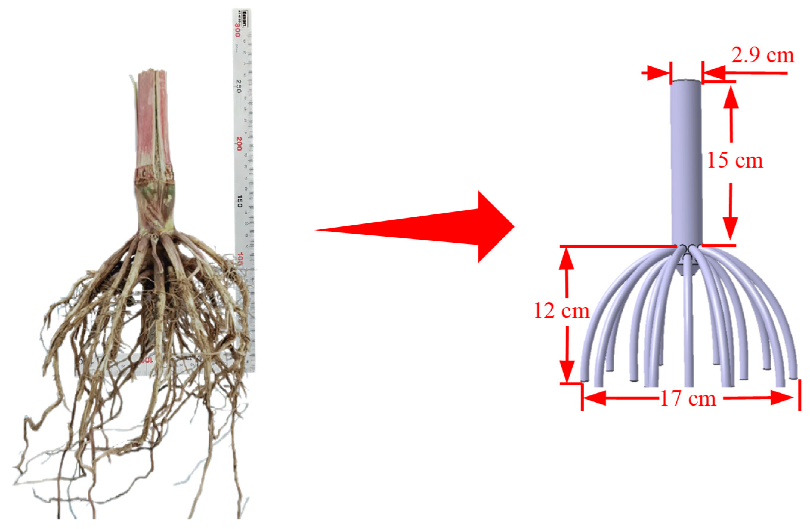
2.1.1. Preparation of Soil and Root–Crowns

The test site was located in Harbin City, Heilongjiang Province (126°63′ N, 45°75′ E). Before the test, a ring cutter was employed to collect soil samples from a 0–10 cm depth. The samples were dried in an oven at 105 °C for 24 h. The average moisture content of the soil was measured to be 24.6% (wet-based), and the average bulk density of the soil was 1.36 g·cm−3 (wet-based) [20]. The ridge shape was measured using a ruler. The height and width of the ridge were 10 cm and 150 cm, respectively. The average spacing of the ridge was 65 cm. Subsequently, the conditions of corn root–crown in the field were sampled and measured. The average spacing of the root–crown was 26 cm, and the average height and diameter of the crown were 15 cm and 2.9 cm, respectively, as shown in Figure 1. To measure the distribution of underground roots, samples were taken from a 20 cm × 20 cm soil layer. A brush was employed to clean the soil attached to the roots, and it was found that the roots were predominantly concentrated within a depth range of 0 to 12 cm and extended laterally up to 17 cm in width. Based on the method specified in GB/T6435-2014 “Determination of Water and Other Active Substances in Feed” [21], the moisture content of the roots and crown was determined, and their values were 15.6% ± 0.8% and 23.23% ± 0.6%, respectively. The JD2C-354 tractor (John Deere, located in Moline, IL, USA) was employed as a power output device in the test.

2.1.2. Device Integrated by Bionic Cutters and Multi-Curve Cutters

When the corn crown was cut by the ordinary curved cutter rotated vertically, the corn crown would slide along the edge of the cutter. It was difficult to make the corn crown enter the overlapping area composed of the moving cutter and the fixed cutter which would negatively affect the length of the corn crown after cutting. The cats could hook out the target and prevent the target from sliding through the special shape of their claws, so we were inspired by the special structure of the cat’s claw to innovate the cutters for crushing corn crowns. The claw of a British Shorthair cat was selected as the bionic prototype. A microscope (OLYMPUS-SZX16, Olympus Corporation in Tokyo, Japan) was employed to obtain the image information of the cat’s claw, and then the inner and outer contours of the claw were extracted using the function command in MATLAB software (2024a), as shown in Figure 2a. The equations of fitting the inner and outer contour curves were obtained, as shown in Equations (1) and (2). The fitting variance R2 for both equations was 0.997, proving that the fitting curves had high accuracy compared to the actual contours of the cat’s claw.
f x 1 = 16 sin 0.41 x 1 0.16 + 14 sin 0.43 x 1 + 2.46            R 2 = 0.997
f x 2 = 0.00164 x 2 3 0.08856 x 2 2 + 1.116 x 2 + 0.3409            R 2 = 0.997
where f(x1) and x1 are the control equation and abscissa of the inner contour of the cat’s claw, respectively. f(x2) and x2 are the control equation and abscissa of the outer contour of the cat’s claw, respectively.
The moving cutter must have sufficient length to smoothly contact the crown. The radius of rotation for the moving cutter designed to cut the corn crown should be at least as large as the growth range of the crown in the context of corn ridge planting, where the width of the upper surface of the ridge is 150 mm. To ensure the stability of the moving cutter, the rotation radius should not be excessively large. Based on the agricultural machinery design manual, the rotation radius of the moving cutter for cutting crowns was designed to be 150 mm.
Based on the distribution characteristics of corn roots in different soil layers, the cutter edges for different soil layers were designed, as shown in Figure 2b. The 0–3 cm soil layer was defined as the shallow soil layer. This layer, being the uppermost, is most susceptible to being disturbed, and it plays a protective role for the soil. Therefore, when designing the cutter edge for the shallow soil layer, it was ensured that the cutter could smoothly penetrate the soil while effectively cutting the roots, minimizing soil damage. Therefore, the sinusoidal curve characteristic was employed to design the cutter edge for the shallow soil layer to reduce soil disturbance [8] as shown in Equation (3). The 3–6 cm soil layer was defined as the middle soil layer. In this layer, corn roots play a pivotal role in the absorption and transportation of water and nutrients [22], with a relatively concentrated distribution. The Archimedean spiral cutter could effectively cut and guide roots, producing a “pulling-out” effect while causing lower soil disturbance [10]. This curve was employed to design the cutter edge for cutting roots in the middle soil layer as shown in Equation (4). The 6–9 cm soil layer was defined as the deep soil layer, representing the maximum depth attainable by the cutter. In this layer, the corn roots are more dispersed. To ensure that the root lengths after cutting could meet the requirements, the cutter needed to have a large sweeping area and preserve the low energy consumption, so an involute cutter edge was employed as shown in Equation (5). The involute curve has a relatively uniform force distribution characteristic, which could effectively reduce energy consumption during cutting roots [5,23].
f x 3 = 9.52 sin 0.62 x 3            0.52 < x 3 < 0
x 4 = 4.67 ( 1 + 0.5 t 4 ) cos ( t 4 ) 3.41 f t 4 = 4.67 ( 1 + 0.5 t 4 ) sin ( t 4 ) + 1.48            0.413 < t 4 < 0.3
x 5 = 6.11 ( cos t 5 + t 5 sin t 5 ) + 4.4 f t 5 = 6.11 ( sin t 5 t 5 cos t 5 ) + 14.56            1.74 < t 5 < 2.28
The device was integrated by cutters rotated vertically for cutting corn root–crowns and could synchronously cut roots and crowns with low soil disturbance. The overlapping length between the moving and fixed cutters directly affected the effect of cutting the crown. Although a longer overlapping length could more thoroughly cut the crown, it would increase the risk of cutter collision. Based on the agricultural machinery design manual, the overlapping length between the moving and fixed cutters was recommended to be 75–85%. Considering assembly errors, the overlapping length was set to 120 mm. To meet agronomic requirements, the length of the crown after cutting should be less than or equal to 50 mm, and a shorter length of the crown after cutting results in a faster decomposition rate. Considering the vibration would occur during the process of cutting the crown, which might cause a change in the relative positions of the moving and fixed cutters. The vertical spacing between the moving cutter and the fixed cutter should not be too small, and it was set to 20 mm after comprehensive consideration. According to the operational requirements of combine harvesters, the height of the corn crown after harvest should be less than 10 cm. Due to uneven terrain, field measurements showed that the crown height ranged from 0 to 15 cm. To adapt to the different heights of the corn crown, the height of the moving cutters should be designed higher than 150 mm. However, if the height of the moving cutters was too large, the stability of the cutter shaft would be affected. After comprehensive consideration, the height of the moving cutters was determined to be 210 mm. Two multi-curve cutters for cutting roots were installed opposite each other at the lower end of the cutter shaft. The device integrated by cutters rotated vertically is shown in Figure 2c.

2.2. Methods

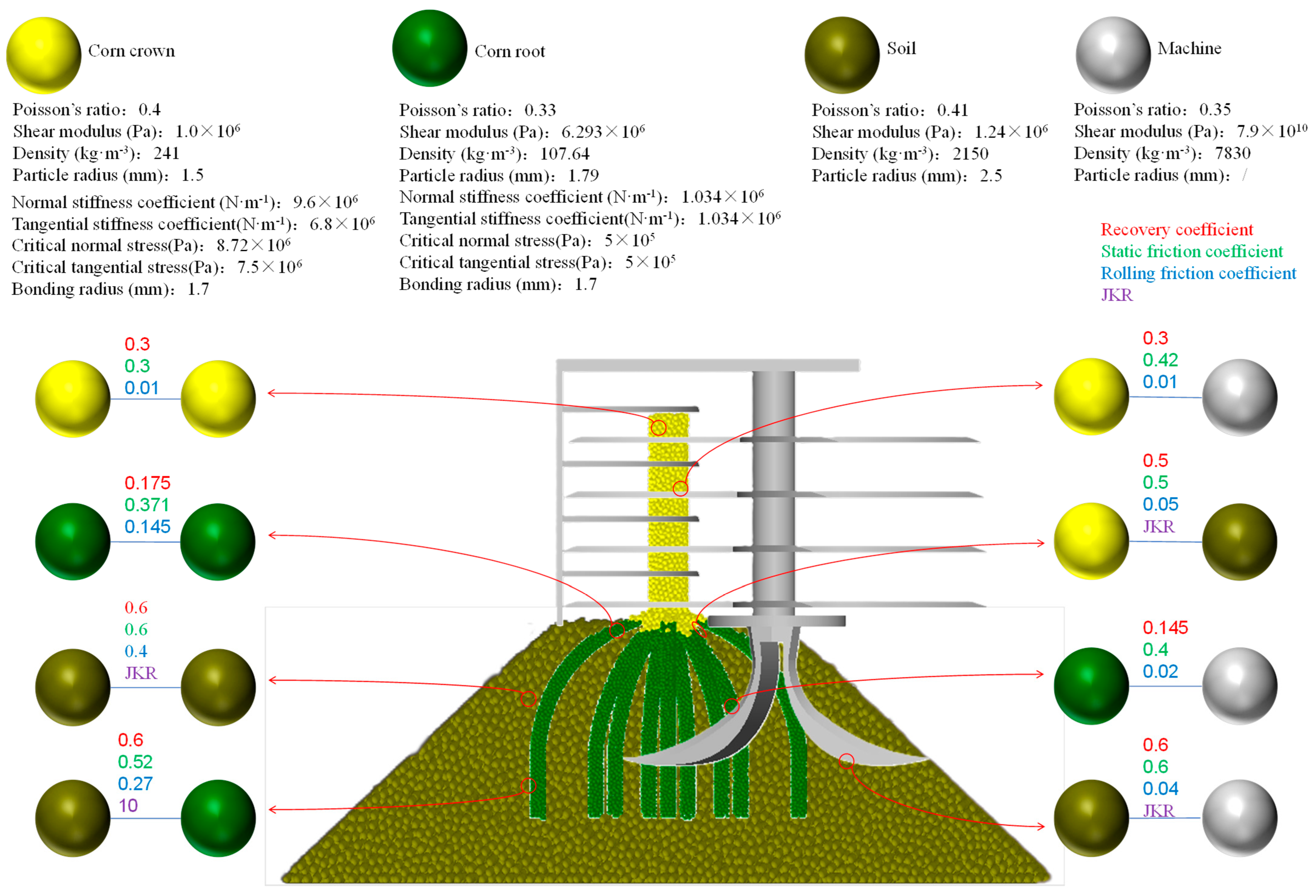
2.2.1. Simulation Test

Based on the measured physical parameters of field soil and the root–crown, the basic parameters for the cutters–soil–root–crown in EDEM (2020) were set as shown in Figure 3 [24,25,26,27,28,29]. The “Hertz–Mindlin with JKR” contact model was selected to simulate the adhesion effects of soil–soil and soil–cutters. The “Hertz–Mindlin with bonding” contact model was selected to simulate the internal structural characteristics and effect of cutting the root–crown.
The process of establishing the root–crown model includes the three aspects. First, the root–crown, excavated from the field, was measured for size. A three-dimensional scanner was employed to capture point cloud data of the root–crown and soil contours and create three-dimensional models of the root–crown and soil particles. Then, the multi-sphere method in EDEM was employed to create simulation models of soil–root–crown. Spherical particles were filled into the regions of roots and crowns. After stabilization, the outer geometry was removed, and bonding contact was generated between crown particles, root particles, and root–crown particles. The overall three-dimensional model of the device was established in CATIA software (V5R21) and saved in “step” format for import into EDEM. To reduce computational time, non-essential structures were simplified, retaining only key components such as the cutter shaft, the moving-fixed cutters for cutting crown, and the multi-curve cutters for cutting roots. The simulation model of cutters–soil–root–crown is shown in Figure 4.

2.2.2. Full-Factorial Test
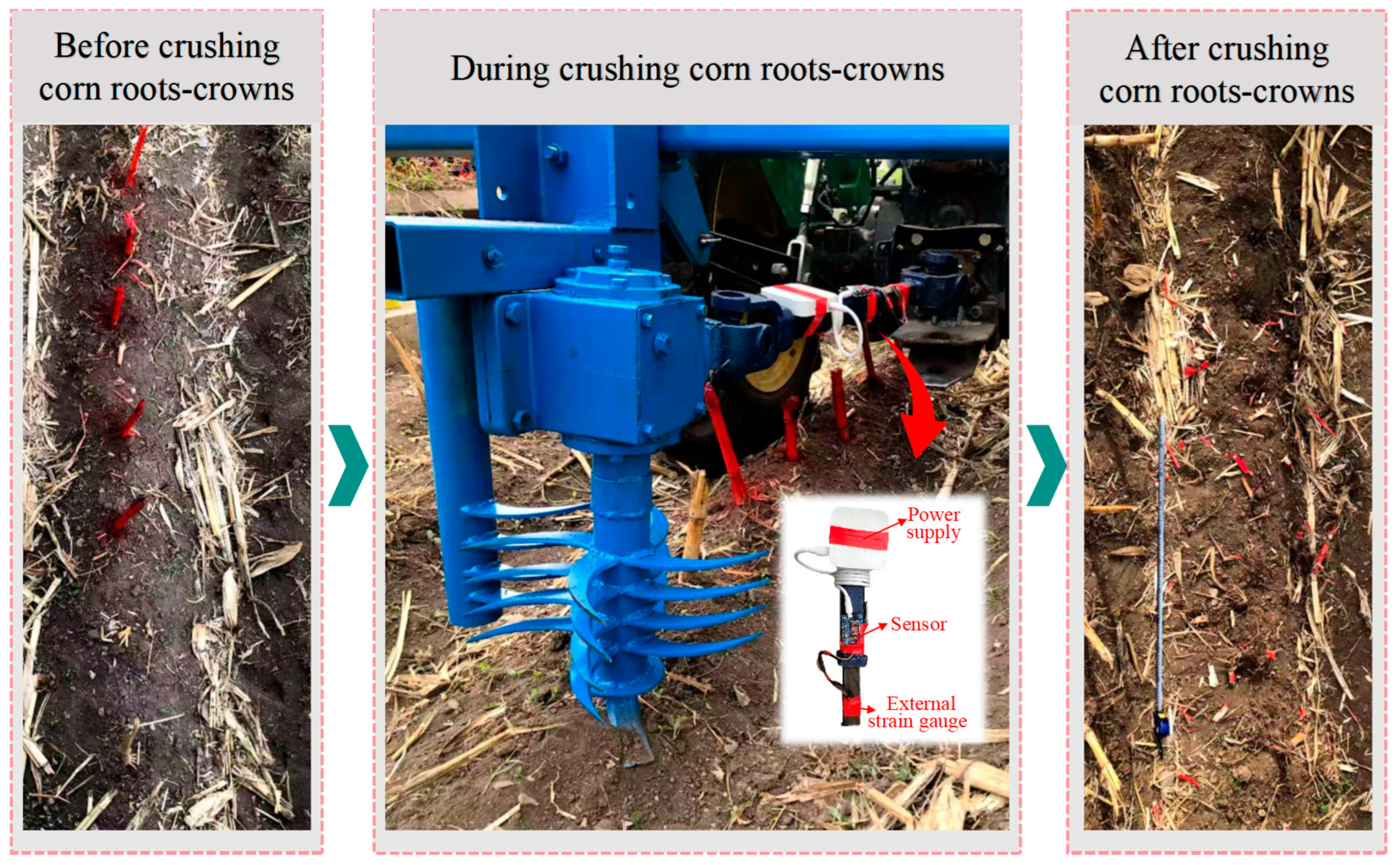
The forward speed of the JD2C-354 tractor is proportional to the rotational speed of the power output shaft, and the relationship between them was obtained by the calibration experiment as shown in Equation (6). Through the field pre-test and referring to the Agricultural Machinery Design Manual, the range of the rotational speed of the cutter shaft in the full factor test was determined. The specific forward speeds of the device were obtained based on a calibrated relationship within the rotational speed range of 380 r·min−1 to 540 r·min−1. The excessive levels in the test might lead to minimal data variation, obscuring outcome differences. Conversely, insufficient levels could introduce excessive data variations, compromising result accuracy and credibility. After comprehensive analysis, five levels were ultimately selected for each factor [30,31].
f x 6 = 225.92 ln x 6 + 458.39            R 2 = 0.978
where f(x6) is the rotational speed of the cutter shaft (r·min−1) and x6 is the forward speed of the device (m·s−1).
To optimize the parameter combination for cutting the root–crown, it was essential to ensure cutting efficiency while minimizing soil disturbance and power consumption. A full-factorial test was designed with forward speed of the device (0.71 m·s−1, 0.84 m·s−1, 1.01 m·s−1, 1.20 m·s−1, 1.43 m·s−1) and the rotational speed of the cutter shaft (380 r·min−1, 420 r·min−1, 460 r·min−1, 500 r·min−1, 540 r·min−1) as test factors. The qualified rate of root–crown length, the rate of soil disturbance, and the power consumption of the device were selected as indicators. The full-factorial test design is shown in Table 1, with three replicates per group.
Through the EDEM post-processing module, the total number of root–crown particles before cutting was denoted as S1, and the number of root–crown particles failing to meet the length requirements after cutting was denoted as S2. The qualified rate of root–crown length y1 in the simulation was calculated via Equation (7):
y 1 = 1 S 2 S 1 × 100 %
where y1 is the qualified rate of root–crown length in the simulation test. S1 is the total number of root–crown particles. S2 is the total number of root–crown particles that failing to meet the requirements of the cut length.
During the process of cutting the root–crown, the disturbed distance by the device was divided into five equidistant segments. The cross-sectional curve of the ridge soil was intercepted, and the cross-sectional areas of each segment were calculated using MATLAB as v1, v2, v3, v4, v5. The volume of the ridge soil was measured as v0. The rate of soil disturbance y2 was calculated via Equation (8). The quintile cross-sectional analysis method was employed to quantitatively characterize the soil disturbance effects during root–crown cutting. However, this method still exhibited significant limitations. Since the ridge was a three-dimensional structure, the disturbance areas were calculated through this method based solely on two-dimensional cross-sections, thereby failing to comprehensively reflect the actual disturbance conditions across the entire ridge. Additionally, the method relied on five equally spaced segments, which, although providing a certain level of measurement accuracy, still overlooked finer details of soil disturbance.
y 2 = v 1 + v 2 + v 3 + v 4 + v 5 5 v 0 × 100 %
where y2 is the rate of soil disturbance (%). v1, v2, v3, v4, v5 are cross-sectional areas of the soil divided in the process of cutting one root–crown, respectively (cm2). v0 is the cross-sectional area of ridge soil (cm2).
The real-time torque on the cutter shaft during the process of cutting the root–crown was obtained using the EDEM analysis module. The average torque of the cutter shaft was calculated. The power consumption of device y3 was calculated via Equation (9).
y 3 = T n 9550 × 100 %
where y3 is the power consumption of the device (kW), T is the torque of the cutter shaft (N·m−1), and n is the rotational speed of the cutter shaft (r·min−1).

2.2.3. Field Test

Before the test of cutting corn root–crown, five corn root–crowns were selected to form a test sample group. The root–crown was pre-treated with spray paint to collect and analyze the root–crown conveniently after cutting. At both the front and back of the test area, a 10 m buffer area was reserved to ensure that the device could maintain the set operating parameters during the process of cutting the root–crown. Additionally, for each test sample group, the experiment was repeated 3 times. The field test is shown in Figure 5.
Before the test, 15 root–crown samples were excavated, and the soil attached to the roots was cleaned with a brush. The cleaned samples were weighed to determine the quality of the root–crown. The average measurement result was recorded as M1. After the test, the root–crowns after cutting were collected and measured. The qualified rate of root–crown length y4 in the field test was calculated via Equation (10). Each group of experiments was repeated five times.
y 4 = 1 M 2 M 1 × 100 %
where y4 is the qualified rate of root–crown length (%). M1 is the quality of root–crown before cutting (g). M2 is the quality of root–crown after cutting that does not meet the requirements (g).
A soil profiler was employed to obtain the cross-sectional area of the soil after cutting the root–crown [32]. The rate of soil disturbance in the field test was calculated via Equation (8).
The system for measuring power consumption was mainly composed of a power supply, sensor (Your cee-HX 711), external strain gauge (GC350-3HA), computer (Lenovo IdeaPad 700-15 ISK) and signal processing software. Before the test, the power supply, sensor and external strain gauge were connected in sequence, and the strain gauge was attached to the universal joint as shown in Figure 5. During the operation of the device, the sensor was used to collect the torque of the cutter shaft, then passed to the computer to record the torque of the cutter shaft with the time. The power consumption of the device was calculated via Equation (9).

3. Results and Discussion

3.1. The Process of Cutting the Root–Crown in the Simulation Test

Since the roots penetrate deep into the soil, the soil provides anchoring support to the entire root system. The process of cutting crowns was divided into three stages: contacting, cradling, and cutting. First, due to the rotational radius of the cutters for cutting crowns being larger than that for cutting roots, the crown was first contacted by moving cutters. Then, under the drive of moving cutters, the crown rotated with the roots as the fulcrum, until the cutting areas of the moving cutters and the fixed cutters began to overlap. The moving cutters continued to rotate and cooperated with the fixed cutter to cut the crown, and the effect of cutting the crown would be improved.
In the process of cutting roots, based on the order of the curves into the different soil layers, the roots at different depths were carried, pulled, and cut in turn. The whole process of cutting roots was divided into three stages: touching, cutting and pulling. As the cutter shaft rotated, the roots were first contacted by the involute edge curve at the outermost end of the rotary center. Due to the uniform distribution of the force of the involute edge, the roots could be effectively cut with low power consumption. For the roots in middle soils, the Archimedes helical cutters generated lower torque and resistance during cutting roots and disturbing soil [33]. An upward pulling effect was exerted on the roots and the roots were pulled upward with the lower soil disturbance. The sinusoidal edge was the last to contact the roots. Due to it being able to smoothly cut into the soil and reduce soil disturbance, the roots would be cut while the shape of the surface soil was maintained. The process of cutting the root–crown is shown in Figure 6.

3.2. Results of the Full-Factor Test

3.2.1. Effect of Different Factors on the Qualified Rate of Root–Crown

According to Table 2, the mathematical model relating the forward speed and rotational speed of the cutter shaft to the qualified rate of root–crown length was significant (p < 0.01). The effect of both the forward speed and the rotational speed of the cutter shaft on the qualified rate of root–crown length was significant (p < 0.01). And there were interactions between them (p < 0.01).
As shown in Figure 7, when the forward speed of the device was kept, the qualified rate of root–crown length increased with the increase in the rotational speed of the cutter shaft. The reason was that as the rotational speed of the cutter shaft increased, the linear velocity of the cutters increased. Therefore, the kinetic energy of the cutters also increased; the force generated by cutters on the crown also increased. Due to the supporting effect of the moving-fixed cutters and soil on the root–crown, forces in different directions were applied to different parts of the root–crown, which led to the effect of tearing the root–crown and further improved the qualified rate of root–crown. Simulation data demonstrated that this special curved cutter could deduce corn crown sliding along the edge of the cutter, and the qualified rate of corn crown length after cutting would be improved during low-speed operations, which fully validated the rationality and superiority of the bionic structural design. When the rotational speed of the cutter shaft was kept, the qualified rate of crown length decreased with the increase in the forward speed of the device. The reason was that the increase in forward speed had a smaller effect on the kinetic energy of the cutters [34]; however, the cycloidal trajectory of moving cutters was significantly affected. As the forward speed increased, the swept area of the cutters was decreased. This would result in missed or incomplete cutting of the root–crown; therefore, the qualified rate of root–crown would decrease [34,35]. The operational efficiency of the device would be affected by low forward speed; therefore, improving the qualified rate of the root–crown length under a high forward speed would be a key technical challenge for future agricultural machinery research. When the forward speed was 0.71 m·s−1 and the rotational speed of the cutter shaft was 540 r·min−1, the qualified rate of root–crown length was highest, and the value was 98.51%. When the forward speed was 1.43 m·s−1 and the rotational speed of the cutter shaft was 360 r·min−1, the qualified rate of root–crown length was lowest, and the value was 83.13%. According to the national standard, the qualification criterion requires that the length of the root–crown should not exceed 10 mm, and the qualified rate of root–crowns should not be lower than 90% [36]. Therefore, the operating range of the device that met the criteria was as follows: the forward speed ranged from 0.71 m·s−1 to 1.2 m·s−1 and the rotational speed of the cutter shaft ranged from 460 r·min−1 to 540 r·min−1.

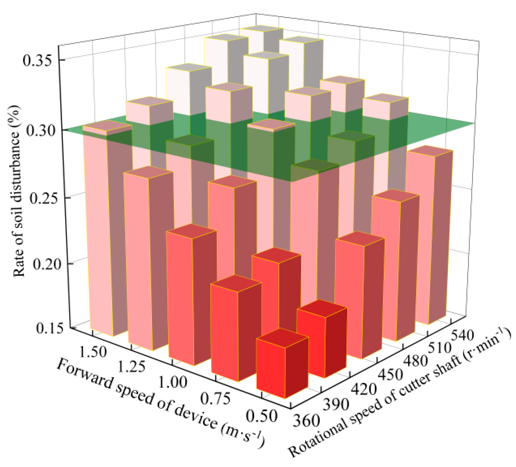
3.2.2. Effect of Different Factors on the Rate of Soil Disturbance

According to Table 3, the mathematical model relating the forward speed and rotational speed of the cutter shaft to the rate of soil disturbance was significant (p < 0.01). The effect of both the forward speed and the rotational speed of the cutter shaft on the rate of soil disturbance was significant (p < 0.01). And there were interactions between them (p < 0.01).
As shown in Figure 8, when the forward speed of the device was kept, the rate of soil disturbance increased with the increase in the rotational speed of the cutter shaft. The reason was that as the rotational speed of the cutter shaft increased, the linear velocity of the tip of the cutters for cutting roots increased, thereby enhancing the kinetic energy of the blade. When the cutters penetrated the soil, the action of the cutters on the soil particles would cause higher kinetic energy, consequently leading to an increase in soil disturbance [37]. When the rotational speed of the cutter shaft was kept, the rate of soil disturbance was increased with the increase in the forward speed of the device. The reason was that the forward speed of the device increased, which resulted in a greater kinetic energy of the cutter. Therefore, the trend of soil moving forward was increased, and the soil disturbance was further aggravated [38]. Simulation data demonstrated that multi-curve cutters based on the distribution characteristics of roots in different soil layers and the corresponding mechanical properties of each soil layer could effectively reduce soil disturbance. This research not only provided a theoretical basis for structural optimization of the device for cutting the root–crown but also helped maintain soil structural stability by minimizing soil disturbance, thereby creating favorable conditions for subsequent soil moisture conservation in farmland. When the forward speed was 1.43 m·s−1 and the rotational speed of the cutter shaft was 540 r·min−1, the rate of soil disturbance was highest, and the value was 35.28%. When the forward speed was 0.71 m·s−1 and the rotational speed of the cutter shaft was 380 r·min−1, the rate of soil disturbance was lowest, and the value was 18.56%. According to the national standard, the rate of soil disturbance should not be exceeded by 30% [39]. Therefore, the operating range of the device that met the criteria was as follows: the forward speed of the device was less than 1.01 m·s−1 and the rotational speed of the cutter shaft was less than 460 r·min−1.

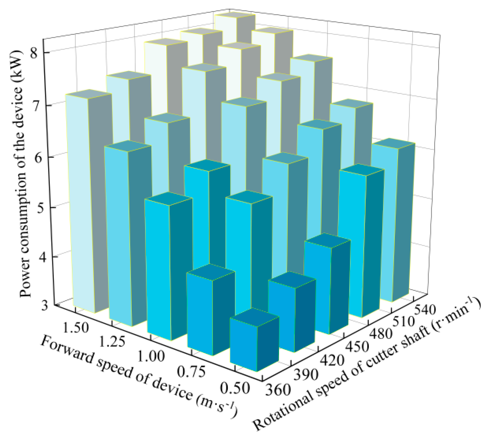
3.2.3. Effect of Different Factors on the Power Consumption of Device

According to Table 4, the mathematical model relating the forward speed and rotational speed of the cutter shaft to the power consumption of the device was significant (p < 0.01). The effect of both the forward speed and the rotational speed of the cutter shaft on the power consumption of the device was significant (p < 0.01), and there were interactions between them (p < 0.01).
As shown in Figure 9, when the forward speed of the device was kept, the power consumption of the device increased with the increase in the rotational speed of the cutter shaft. The reason was that as the rotational speed of the cutter shaft increased, the kinetic energy of the cutters significantly increased, thereby improving energy conversion efficiency and resulting in an enhancement in the qualification rate of cutting the root–crown length. However, it also led to a significant increase in the power consumption of the device [35]. Additionally, with the increase in the rotational speed of the cutter shaft, the soil resistance acting on the cutters for cutting roots also increases. To overcome soil resistance, a corresponding increase in power consumption was required, which was another reason for the increase in power consumption. When the rotational speed of the cutter shaft was kept, the power consumption of the device increased with the increase in the forward speed of the device. The reason was that as the forward speed of the device increased, the cutters for cutting roots must overcome greater soil resistance, resulting in an increase in power consumption of the device [40]. Future studies could focus on jointly optimizing the rotational speed of the cutter shaft and the forward speed of the cutter shaft while incorporating soil characteristics to establish dynamic resistance models, aiming to minimize power consumption while maintaining compliance with the qualified rate of root–crown length. When the forward speed was 1.43 m·s−1 and the rotational speed of the cutter shaft was 540 r·min−1, the power consumption of the device reached the highest value of 8.239 kW. When the forward speed was 0.71 m·s−1 and the rotational speed of the cutter shaft was 380 r·min−1, the power consumption was lowest, the value of which was 3.835 kW.

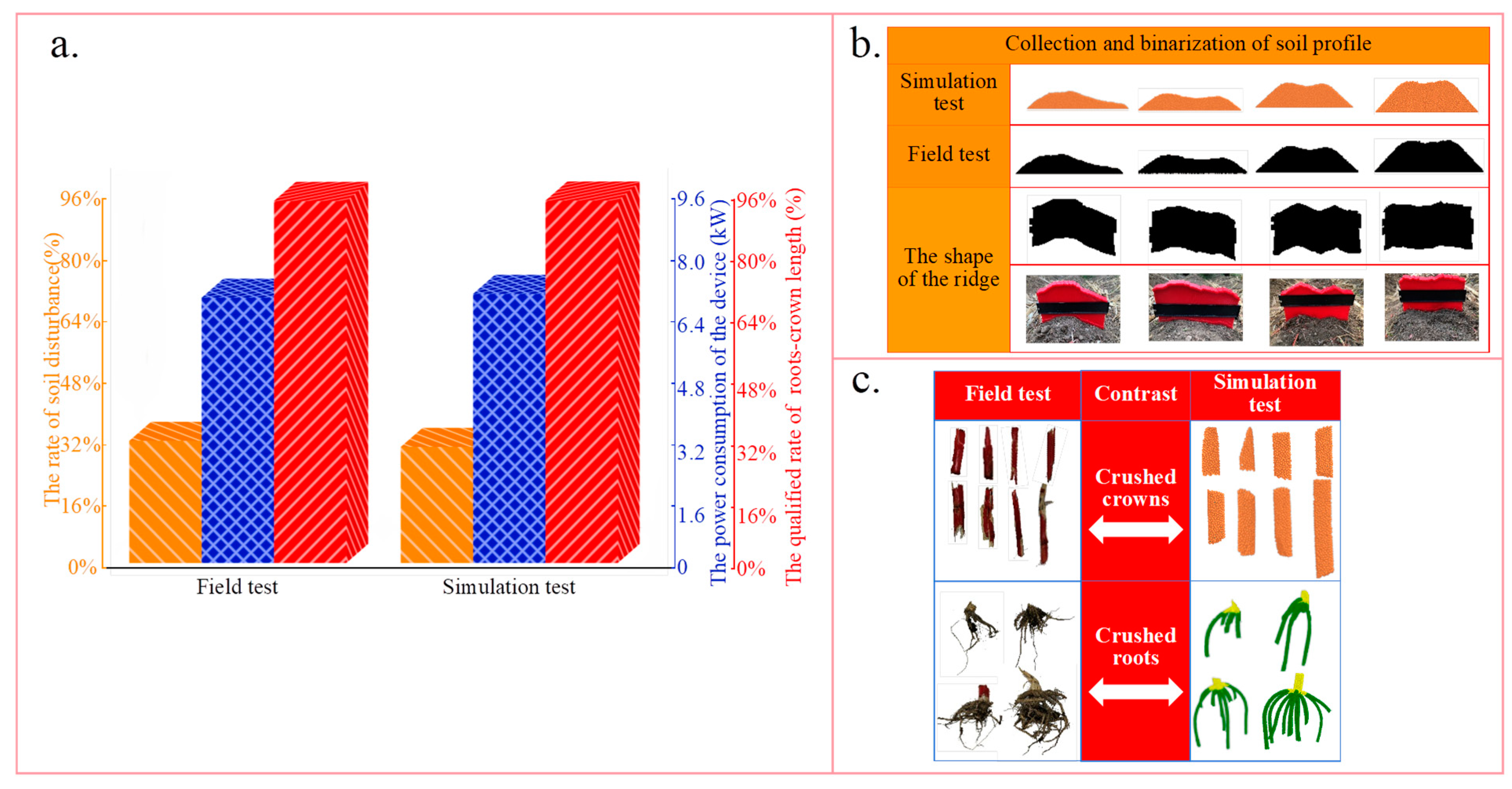
3.3. Consistency of the Results in the Field and Simulation Tests

Under the condition of the forward speed of 1.01 m·s−1 and the rotational speed of the cutter shaft of 460 r·min−1, the consistency of the results in the field and simulation tests results was analyzed, and the results are shown in Figure 10. The power consumption of the device measured in the field test was 6.9 kW, and the error relating to the results in the simulation was 0.1 kW. The small error effectively proved the effectiveness and reliability of the developed torque measurement system in the field test and also verified the accuracy of the power consumption calculation of the device based on the cutter shaft torque in the simulation test. Furthermore, it was also proved that the simulation accurately captured the interaction forces among the cutters, root–crown, and soil, providing strong support for subsequent research. The qualified rate of root–crown length in the field test was 94.18%, and the error relating to the results in the simulation test was 0.1%. The comparison revealed that the morphology of the root–crown after cutting was highly consistent between the field test and simulation test, which proved the feasibility of employing the Bonding model and the JKR model to simulate the effect of cutting the root–crown in the simulation. The error in the rate of soil disturbance between the field and simulation tests was only 1.59%. In the two tests, the ridge after disturbing showed the shape change from “M” to “Ʌ” along the forward direction of the device, which further validated the applicability and accuracy of the JKR model in simulating the interaction between cutters and soil. When the device moved forward, the soil in the deep soil layer was disturbed by the involute curve edge that had the maximum turning radius. The soil would be thrown from the middle of the ridge outwards. In the early stage of cutting roots, this action results in an “M”-shaped ridge. During the forward movement of the device and the continuous rotation of the cutter shaft, the Archimedean-spiral edge and sine curve edge began to disturb the middle soil layer and the surface soil layer, respectively. The soil within rotation areas of the two types of edges would be thrown from the rotation center of the cutter shaft. Consequently, the “Ʌ”-shaped ridge evolved in the latter stage of cutting roots. We discovered that this particular shape of the ridge was driven by the multi-curve cutter. Importantly, this shape corresponded to the lower rate of soil disturbance. This minimal disturbance is beneficial for protecting the soil structure and fertility, maintaining soil biodiversity, and enhancing the efficiency of water resource utilization.

4. Conclusions

The bionic cutter for cutting crowns was designed through reverse engineering technology, and the multi-curve cutter for cutting roots was designed based on the distribution characteristics of roots in different soil layers. A full-factorial test was designed, and DEM was employed to simulate the process of cutting the root–crown. A field test was conducted to validate the accuracy of the simulation results. The significance and effect of the forward speed and rotational speed of the cutter shaft on the qualified rate of the root–crown length, the rate of soil disturbance, and the power consumption of the device were investigated.
The qualified rate of the root–crown length was significantly affected by the forward speed and the rotational speed of the cutter shaft. The moving cutters followed a cycloidal trajectory and cooperated with the fixed cutter to support and cut the crown. The multi-curve cutter sequentially carried, pulled, and cut in the soil through curves at different positions, achieving effective root cutting. As the rotational speed of the cutter shaft increased, the qualified rate of the root–crown length increased. An increase in forward speed led to a decrease in the qualified rate of the root–crown length. When the forward speed was 0.71 m·s−1 and the rotational speed of the cutter shaft was 540 r·min−1, the qualified rate of the root–crown length was highest, and the value was 98.51%. When the forward speed was 1.43 m·s−1 and the rotational speed of the cutter shaft was 360 r·min−1, the qualified rate of the root–crown length was lowest, and the value was 83.13%.
The rate of soil disturbance was significantly affected by the forward speed and the rotational speed of the cutter shaft. Due to the presence of the roots–soil composite, soil disturbance was exacerbated when the cutters contacted and cut the roots. As the rotational speed of the cutter shaft increased, the rate of soil disturbance increased, and a similar trend was observed with the increase in forward speed. When the forward speed was 1.43 m·s−1 and the rotational speed of the cutter shaft was 540 r·min−1, the rate of soil disturbance was highest, and the value was 35.28%. When the forward speed was 0.71 m·s−1 and the rotational speed of the cutter shaft was 380 r·min−1, the rate of soil disturbance was lowest, and the value was 18.56%.
The power consumption of the device was significantly affected by the forward speed and the rotational speed of the cutter shaft. As the rotational speed of the cutter shaft increased, the power consumption of the device increased. Similarly, as the forward speed increased, more energy was required to overcome the soil resistance, resulting in higher power consumption of the device. When the forward speed was 1.43 m·s−1 and the rotational speed of the cutter shaft was 540 r·min−1, the power consumption of the device reached the highest value of 8.239 kW. When the forward speed was 0.71 m·s−1 and the rotational speed of the cutter shaft was 380 r·min−1, the power consumption was lowest, and the value was 3.835 kW.
To pursue lower power consumption of the device and minimize soil disturbance, it was recommended to adopt the lower rotational speed of the cutter shaft and forward speed in practical applications. Although this might result in a slight decrease in the qualified rate of root–crown length, the national standard of 90% could still be met. However, the operational efficiency of the device would be affected at lower forward speeds. In the future, the relationship among the qualified rate of root–crown length, soil disturbance, and power consumption should be balanced to improve the operational efficiency of the device. Additionally, the device would be employed to cut the root crowns of various crops to test its adaptability. The optimal operating conditions of the device were determined to be the forward speed of 0.71 m·s−1 and the rotational speed of the cutter shaft of 380 r·min−1. Under these conditions, the qualified rate of the root–crown length reached 90.54%, the rate of soil disturbance was 18.56%, and the power consumption of the device was 3.835 kW.

Author Contributions

Project administration, X.F. and Q.W.; conceptualization, Y.G., B.Q. and L.W.; methodology, S.G., Q.W. and J.T.; writing—original draft preparation, C.X.; writing—review and editing, X.F. and C.X. All authors have read and agreed to the published version of the manuscript.

Funding

This work was supported by the National Natural Science Foundation of China (Grant No. 52205253), the National Natural Science Foundation of Heilongjiang Province of China (Grant No.LH2022E007), Heilongjiang Provincial Key Research and Development Program (Grant No.2022ZX05B04) and the Key Laboratory of High Efficient Seeding and Harvesting Equipments, Ministry of Agriculture and Rural Affairs of the People’s Republic of China, Northeast Agricultural University, Harbin 150030, China (Grant No. 55200412).

Institutional Review Board Statement

Not applicable.

Data Availability Statement

The data presented in this study are available on request from the corresponding author.

Acknowledgments

Thanks to the “National Natural Science Foundation of China, the National Natural Science Foundation of Heilongjiang Province of China, Heilongjiang Provincial Key Research and Development Program and the Key Laboratory of High Efficient Seeding and Harvesting Equipments” for the financing of this research.

Conflicts of Interest

The authors declare no conflicts of interest.

References

  1. Feng, X.; Yao, J.Y.; Gao, Y.P.; Zeng, L.C.; Wang, L.J.; Wang, B.; Yang, Z.L. Review of Root-Stubble Characteristics and Root-Stubble Crushing and Clearing Technologies for Conservation Tillage. Sustainability 2024, 16, 8508. [Google Scholar] [CrossRef]
  2. Li, M.X.; Jiang, H.; Li, R.D.; Tao, Y.Q.; Li, X.; Qiu, Z.P. Strengthening straw returning by coupling functional microbial agents with organic fertilizers. China Environ. Sci. 2025, 45, 870–881. [Google Scholar]
  3. Hua, L.; Gao, Y.; Li, D.Y.; Yang, Z.X.; Liu, Z.P. Effects of Different Straw Return Methods on Farmland Carbon Footprint and Water Footprint. Agriculture 2025, 15, 73. [Google Scholar]
  4. Zhou, G.P.; Gao, S.J.; Lu, Y.H.; Liao, Y.L.; Nie, J.; Cao, W.D. Co-incorporation of green manure and rice straw improves rice production, soil chemical, biochemical and microbiological properties in a typical paddy field in southern China. Soil Tillage Res. 2020, 197, 104499. [Google Scholar]
  5. Li, S.C.; Diao, P.S.; Li, X.H.; Zhao, Y.L.; Zhao, H.L.; Zhao, H.D. Design and Optimization for Straw Treatment Device Using Discrete Element Method (DEM). Agriculture 2025, 15, 152. [Google Scholar] [CrossRef]
  6. Zhao, H.B.; He, J.; Zheng, Z.Q.; Zhang, Z.G.; Liu, W.Z. Strip tillage inter-row residue side-throwing device of no/minimum-till seeder for anti-blocking and seedbed-cleaning. Trans. CSAM 2018, 51, 24–34. [Google Scholar]
  7. Zhao, H.B.; He, J.; Li, H.W.; Liu, C.G.; Zheng, K.; Zhang, Z.Q. Design and experiment of strip rotary-cut-throw anti-blocking implement. Trans. CSAM 2018, 49, 65–75. [Google Scholar]
  8. Liao, Q.X.; Xie, H.M.; Zhang, Q.S.; Zhang, J.Q.; Ao, Q.; Wang, L. Design and Experiment of Driven Disc Plow and Double-edged Rotary Tillage Combined Tiller. Trans. CSAM 2023, 54, 99–110,195. [Google Scholar]
  9. Yao, W.Y.; Diao, P.S.; Miao, H.Q.; Li, S.C. Design and Experiment of Anti-Blocking Components for Shallow Stubble Clearing Based on Soil Bin Test. Agriculture 2022, 12, 1728. [Google Scholar] [CrossRef]
  10. Lin, J.; Lv, Z.Y.; Li, H.Z.; Wang, X.Y.; Wang, D.R. Design and Experiment of Passive Anti-winding Stubble Breaking and Ridge Cleaning Device for No-tillage Planter. Trans. CSAM 2023, 54, 19–27. [Google Scholar]
  11. Wang, H.Y.; Ge, Z.W.; Yong, C.M.; You, Y.; Li, Z.H.; Li, C.R.; Lu, Q.Q.; Wang, D.C.; Fang, X.F. Optimization and testing of the bionic chopping cutter for silage maize. Trans. CSAE 2025, 41, 87–97. [Google Scholar]
  12. Zhao, Z.; Wang, Z.G.; Zhao, B.T.; Song, Y.Q.; Xin, M.J. Design and research of a cutting of a cutting blade for corn stalks based on a bionic principle. INMATEH Agric. Eng. 2022, 63, 3. [Google Scholar]
  13. Qi, H.Y.; Ma, Z.C.; Xu, Z.H.; Wang, S.; Ma, Y.H.; Wu, S.Y.; Guo, M.Z. The Design and Experimental Validation of a Biomimetic Stubble-Cutting Device Inspired by a Leaf-Cutting Ant’s Mandibles. Biomimetics 2023, 8, 555. [Google Scholar] [CrossRef]
  14. Hu, J.P.; Xu, L.Z.; Yu, Y.; Lu, J.; Han, D.L.; Chai, X.Y.; Wu, Q.H.; Zhu, L.J. Design and Experiment of Bionic Straw-Cutting Blades Based on Locusta Migratoria Manilensis. Agriculture 2023, 13, 2231. [Google Scholar] [CrossRef]
  15. Qian, J.; Ma, S.C.; Xu, Y.; Li, W.Y.; Wang, C.Y.; Yang, S.; Wang, F.L. Experimental study on the sugarcane stubble base-cutting mechanism. Biosyst. Eng. 2024, 245, 122–134. [Google Scholar]
  16. Gu, F.W.; Zhao, Y.Q.; Wu, F.; Hu, Z.C.; Shi, L.L. Simulation analysis and experimental validation of conveying device in uniform rushed straw throwing and seed-sowing Machines using CFD-DEM coupled approach. Comput. Electron. Agric. 2022, 193, 106720. [Google Scholar]
  17. Cao, X.P.; Wang, Q.J.; Li, H.W.; He, J.; Lu, C.Y. Research with Side Cutter and Stubble Clean Disk of Corn No-till Seeder. Trans. CSAM 2021, 52, 36–44. [Google Scholar]
  18. Zhao, S.H.; Wang, J.Y.; Yang, C.; Chen, J.Q.; Yang, Y.Q. Design and experiment of stubble chopper under conservation tillage. Trans. CSAM 2019, 50, 57–68. [Google Scholar]
  19. Liu, X.T.; Qi, H.Y.; Wang, S.; Xu, Z.H.; Gao, P.; Fu, D.P.; Ma, Y.H. The Design and Experimentation of a Wing-Shaped Stubble-Breaking Device for Maize Stubbles. Agriculture 2024, 14, 2108. [Google Scholar] [CrossRef]
  20. Zhang, Z.; Zhang, Y.L.; Henderson, M.; Wang, G.B.; Chen, M.Y.; Fu, Y.; Dou, Z.Y.; Zhou, W.Y.; Huang, W.W.; Liu, B.H. Effect of Land Use Type on Soil Moisture Dynamics in the Sloping Lands of the Black Soil (Mollisols) Region of Northeast China. Agriculture 2024, 14, 1261. [Google Scholar] [CrossRef]
  21. GB/T 6435-2014; Determination of Moisture in Feeds. Standards Press of China: Beijing, China, 2014.
  22. Xu, C.C.; Zhang, P.; Wang, Y.Y.; Luo, N.; Tian, B.J.; Liu, X.W.; Wang, P.; Huang, S.B. Grain yield and grain moisture associations with leaf, stem and root characteristics in maize. J. Integr. Agric. 2022, 21, 1941–1951. [Google Scholar]
  23. Sun, Y.X.; Dou, G.Z.; Duan, W.B.; Chen, X.H.; Zheng, J.; Xin, L.M.; Bai, L. Involute-arc-leg for Multi-legged Robot: High Stability and Low Energy Consumption. Mech. Mach. Theory 2022, 170, 104701. [Google Scholar]
  24. Tang, Z.Y.; Gong, H.; Wu, S.L.; Zeng, Z.W.; Wang, Z.Q.; Zhou, Y.H.; Fu, D.B.; Liu, C.; Cai, Y.H.; Qi, L. Modelling of paddy soil using the CFD-DEM coupling method. Soil Tillage Res. 2023, 226, 105591. [Google Scholar]
  25. Zhang, S.L.; Zhao, H.B.; Wang, X.Z.; Dong, J.X.; Zhao, P.F.; Yang, F.F.; Chen, X.H.; Liu, F.; Huang, Y.X. Discrete element modeling and shear properties of the maize stubble-soil complex. Comput. Electron. Agric. 2023, 204, 107519. [Google Scholar]
  26. Yuan, Y.W.; Wang, J.Y.; Zhang, X.; Zhao, S.H. Effect of Rotary Speed on Soil and Straw Throwing Process by Stubble-Crushing Blade for Strip Tillage Using DEM-CFD. Agriculture 2023, 13, 877. [Google Scholar] [CrossRef]
  27. Zhang, J.; Xia, M.; Chen, W.; Yuan, D.; Wu, C.Y.; Zhu, J.P. Simulation Analysis and Experiments for Blade-Soil-Straw Interaction under Deep Ploughing Based on the Discrete Element Method. Agriculture 2023, 13, 136. [Google Scholar] [CrossRef]
  28. Wang, Q.; Wang, Z.M.; Zhang, Z.H.; Zhang, K.; Yao, S.; Zhou, W.Q.; Sun, X.B.; Wang, J.W. Design and Test of Bionic Elastic Row Cleaner with Improved Straw Cleaning Performance. Agriculture 2024, 14, 186. [Google Scholar] [CrossRef]
  29. Shi, Y.Y.; Rex, S.X.; Wang, X.C.; Hu, Z.C.; Newman, D.; Ding, W.M. Numerical simulation and field tests of minimum-tillage planter with straw smashing and strip laying based on EDEM software. Comput. Electron. Agric. 2019, 166, 105021. [Google Scholar]
  30. Hou, S.Y.; Ji, Z.C.; Xue, D.H.; Wang, X.; Feng, B.J.; Chen, H.T. Improved Design and Test of Straw Cleaning Device Suitable for No-tillage Seeding Unit. Trans. CSAM 2023, 54, 111–122. [Google Scholar]
  31. Xiao, M.H.; Niu, Y.; Wang, K.X.; Zhu, Y.J.; Zhou, J.P.; Ma, R.Q. Design of Self-excited Vibrating Rotary Tiller and Analysis of Its Performance in Reducing Torsion and Consumption. Trans. CSAM 2022, 53, 52–63. [Google Scholar]
  32. Hou, S.Y.; Chen, H.T.; Zhou, Z.; Wei, Z.P.; Zhang, Y.L. Design and test of lateral stubble cleaning blade for corn stubble field. Trans. CSAE 2020, 36, 59–69. [Google Scholar]
  33. Zhang, S.L.; Huang, Y.X.; Gao, X.J.; Bi, Y.B.; Dong, J.X.; Zhao, H.B.; Zhao, P.F.; Jia, X. Evaluating the influence of straight-plain types of rotary tiller blades with various edge curves on maize residue using DEM. Biosyst. Eng. 2025, 250, 49–61. [Google Scholar] [CrossRef]
  34. Zhao, Z.; Hou, J.L.; Guo, P.; Xia, C.; Yan, H.P.; Wang, D.W. Analysis of Soil-Straw Movement Behavior in Saline-Alkali Soil Under Dual-Axis Rotary Tillage Based on EDEM. Agriculture 2025, 15, 337. [Google Scholar] [CrossRef]
  35. Wang, J.; Wang, X.Y.; Li, H.W.; He, J.; Lu, C.Y.; Liu, D. Design and Experiment of Rice Straw Chopping Device for Agitation Sliding Cutting and Tearing. Trans. CSAM 2021, 52, 28–40. [Google Scholar]
  36. GB/T 24675.5-2021; SAC/TC 201 (National Agricultural Machinery Standardization Technical Committee). Conservation Tillage Equipment-Part 5: Smashed Root Stubble Machine. Standards Press of China: Beijing, China, 2021.
  37. Zhai, S.K.; Shi, Y.X.; Zhou, J.C.; Liu, J.F.; Huang, D.F.; Zou, A.R.; Jiang, P. Simulation Optimization and Experimental Study of the Working Performance of a Vertical Rotary Tiller Based on the Discrete Element Method. Actuators 2022, 11, 342. [Google Scholar] [CrossRef]
  38. Zhao, J.L.; Lu, Y.; Wang, X.G.; Zhuang, J.; Han, Z.W. A bionic profiling-energy storage device based on MBD-DEM coupled simulation optimization reducing the energy consumption of deep loosening. Soil Tillage Res. 2023, 234, 105824. [Google Scholar] [CrossRef]
  39. General Office of the Ministry of Agriculture and Rural Affairs, General Office of the Ministry of Finance. Notice on Printing and Distributing the “Implementation Guidance Opinions for the Conservation Tillage Action Plan for Northeast Black Soil Regions”. In Gazette of the Ministry of Agriculture and Rural Affairs of the People’s Republic of China; Ministry of Agriculture and Rural Affairs, PRC: Beijing, China, 2020; Volume 4, pp. 41–44. [Google Scholar]
  40. Li, X.; Zhang, Y.P.; He, H.J.; Wang, B.; Zhou, H.; Geng, D.Y.; Zhang, Y.Z. Design and Experiment of Row Cleaner with Staggered Disc Teeth for No-Till Planter. Agriculture 2023, 13, 1373. [Google Scholar] [CrossRef]
Figure 1. Model of corn root–crown.
Agriculture 15 00717 g001
Figure 2. (a) Bionic cutter for cutting crown. (b) Multi-curve cutter for cutting roots. (c) Device integrated by cutters.
Agriculture 15 00717 g002
Figure 3. The physical parameters of particles in the simulation.
Agriculture 15 00717 g003
Figure 4. The simulation model of cutters–soil–root–crown.
Agriculture 15 00717 g004
Figure 5. The process of field test.
Agriculture 15 00717 g005
Figure 6. The process of cutting the root–crown.
Agriculture 15 00717 g006
Figure 7. Effect of different factors on the qualified rate of root–crown.
Agriculture 15 00717 g007
Figure 8. Effect of different factors on the rate of soil disturbance.
Agriculture 15 00717 g008
Figure 9. Effect of different factors on the power consumption of the device.
Agriculture 15 00717 g009
Figure 10. Consistency of the results in the field and simulation tests. (a) The comparison of indicators. (b) The effects of soil disturbance. (c) The effects of cutting the root–crown.
Agriculture 15 00717 g010
Table 1. Full-factorial test.
Test LevelForward Speed of Device (m·s−1)Rotational Speed of Cutter Shaft (r·min−1)
10.71380
20.84420
31.01460
41.20500
51.43540
Table 2. The mathematical model relating the forward speed and rotational speed of the cutter shaft to the qualified rate of root–crown length.
SourceSum of SquaresdfMean SquareF Valuep-Value Prob > F
Model0.15246.305 × 10−3346.30<0.0001
A0.04240.011577.07<0.0001
B0.1040.0261402.23<0.0001
AB7.175 × 10−3164.484 × 10−424.63<0.0001
Pure Error9.104 × 10−4501.821 × 10−5
Cor Total0.1574
p < 0.01 indicate significant.
Table 3. The mathematical model relating the forward speed and rotational speed of the cutter shaft to the rate of soil disturbance.
SourceSum of SquaresdfMean SquareF Valuep-Value Prob > F
Model0.17247.229 × 10−34952.96<0.0001
A0.10040.02517,068.60<0.0001
B0.06940.01711,887.03<0.0001
AB4.449 × 10−3162.781 × 10−4190.54<0.0001
Pure Error7.297 × 10−5501.459 × 10−6
Cor Total0.1774
p < 0.01 indicate significant.
Table 4. The mathematical model relating forward speed and rotational speed of the cutter shaft to the power consumption of the device.
SourceSum of SquaresdfMean SquareF Valuep-Value Prob > F
Model116.31244.8585,736.39<0.0001
A76.57419.143.387 × 105<0.0001
B35.8848.971.587 × 105<0.0001
AB3.86160.244270.63<0.0001
Pure Error2.826 × 10−3505.652 × 10−5
Cor Total116.3174
p < 0.01 indicate significant.
Disclaimer/Publisher’s Note: The statements, opinions and data contained in all publications are solely those of the individual author(s) and contributor(s) and not of MDPI and/or the editor(s). MDPI and/or the editor(s) disclaim responsibility for any injury to people or property resulting from any ideas, methods, instructions or products referred to in the content.

