Article

Design and Experimentation on a Pneumatic Corn Seed Metering Device with Assisted Seed-Filling and Airflow-Guided Seed Release

by
Jiahua Yan
1,2,
Guangwei Wu
1,2,*,
Rui Liu
2,
Liwei Li
2,
Yuejin Xiao
2,
Junxian Guo
1 and
Bingxin Yan
2,*
1
College of Mechanical and Electrical Engineering, Xinjiang Agricultural University, Urumqi 830052, China
2
Intelligent Equipment Research Center, Beijing Academy of Agriculture and Forestry Sciences, Beijing 100097, China
*
Authors to whom correspondence should be addressed.
Agriculture 2025, 15(7), 745; https://doi.org/10.3390/agriculture15070745
Submission received: 24 February 2025 / Revised: 21 March 2025 / Accepted: 26 March 2025 / Published: 31 March 2025
(This article belongs to the Section Agricultural Technology)

Abstract

:
In view of the problem that the qualified index of grain spacing deteriorates during high-speed operation of the pneumatic corn seed dispenser, a new method of homologous dual-action positive-pressure-assisted seed filling and seed release is proposed, and a pneumatic corn seed dispenser with assisted inflow filling is designed. The structure and working principle of the seed dispenser are explained, and a theoretical analysis is carried out on the seed filling and seed release process in the seed guide tube. The key structural parameters of the conical deflector-groove seed metering disc and the homologous airflow-assisted seed release mechanism are determined. The test factors were working pressure and operating speed, and the evaluation indicators were the qualified particle spacing index, missed sowing index, resowing index, and qualified particle spacing variation coefficient. A full-factor bench test was carried out, and the test results showed that when the sowing speed was 6 km/h and the working pressure was 5 kPa, the qualified particle spacing index was 96.37%, the missed sowing index was 0.30%, the resowing index was 3.33%, and the coefficient of variation in the qualified particle spacing was 17.37%. The results of the field test showed that when the operating speed was 6 km/h and the working pressure was 5 kPa, the qualified particle spacing index was 95.30%, the missed sowing index was 2.33%, and the resowing index was 2.37%. All indicators met the technical requirements for precision single-seed maize sowing.

1. Introduction

The quality of corn sowing is one of the most critical factors influencing both the corn yield and quality [1,2]. The advancement of precision seeding technology for corn is essential for enhancing farmland productivity and resource utilisation efficiency [3]. Precision planters for corn offer high sowing accuracy, effectively minimising seed waste and boosting yields [4]. Research has demonstrated that a 10% reduction in the coefficient of variation (CV) of qualified grain spacing during precision sowing can increase yields by 1220 kg/hm2 [5]. As the core component of the precision maize planter, the seed metering device directly impacts the uniformity of seed spacing and the coefficient of variation (CV) of seed distribution during the filling and seeding processes [6,7].
Maize precision seed metering devices are primarily categorised into two types: mechanical seed metering devices and pneumatic seed metering devices [8]. Mechanical seed metering devices include various types, such as finger-clip, spoon-wheel, disc, eye-shaped wheel, and hole-belt designs [3,9,10,11,12]. These seed metering devices offer advantages such as a simple design, a compact structure, a high reliability, and a low cost, making them widely used in field seeding operations for fine crops like corn and soybeans. However, mechanical seed metering devices have relatively complex structures, require more maintenance, and result in higher seed damage rates. They are also more susceptible to soil conditions and exhibit a reduced accuracy during high-speed seeding operations [4]. Pneumatic seed metering devices include several types, such as air-suction, air-pressure, and air-blowing models [7,8,13]. Among them, the air-pressure seed metering device can achieve seed filling, discharging, and conveying under air pressure. During high-speed seeding operations, it allows for a precise control of the seed spacing [14,15], making it a focal point of research both domestically and internationally. Scholars have conducted extensive studies to improve the high-speed operational performance of air-pressure seed metering devices. The Exact Emerge seed planter from John Deere features a high-speed rotating seed-metering drum and an air-pressure control system. The seed disc is equipped with a circular arc-shaped seed guide groove, which reduces friction between the seeds, enabling precise sowing at speeds of up to 16 km/h. The Early Riser 2160 pneumatic precision seed metering device from Case Corporation in the USA incorporates a specially designed grooved seed disturbance mechanism on the seed disc, which enhances seed separation during high-speed rotation, making it ideal for high-speed precision sowing operations. Shi Song et al. [16] designed a pneumatic combined perforated corn precision seed metering device to address the issue of inaccurate seed spacing during precision corn seeding. The design integrates perforated plates and vibrating plates, achieving a qualified seed spacing index of over 97%. Yang Shandong et al. [17] developed a side-mounted positive-pressure corn seed metering device to mitigate uneven seed distribution and seed damage in pneumatic seed distributors. After seed classification, the qualified seed spacing index reached 89.36%. Sun Wensheng et al. [18] designed a dual-cavity, double-disc, staggered, synchronised rotary pneumatic high-speed precision seed metering device to address the issues of poor seed distribution uniformity and the lack of targeted evaluation indexes for the zigzag seeding effect during high-speed (10–16 km/h) operation of precision seed metering devices under the wide-narrow row zigzag planting pattern for maize. Under the optimal parameter combination, this device achieved a zigzag qualification index of 94% and a coefficient of variation in double-row plant spacing of 6.11%, meeting the requirements for high-speed precision seeding in this planting pattern.
The aforementioned research primarily focused on enhancing seed population disturbance by modifying the seed metering disc or the structure of the metering holes to improve the seed filling performance. Currently, systematic research on the mechanism of airflow-assisted seed movement during the seed filling and seed release stages remains insufficient, leading to notable theoretical and practical challenges. With the increasing demand for high-efficiency and precision seeding in modern agriculture, an in-depth investigation into airflow-assisted seed movement is essential for improving the seed filling performance and seeding accuracy. To address this gap, this paper proposes an air-pressure-assisted maize seed metering device designed to improve seed spacing uniformity, which is often compromised by metering hole omissions due to short filling duration and fluctuations in seed impact velocity at the seed guide tube inlet during the seed release stage. The proposed device employs a conical guide-slot metering disc, where the positive airflow within the guide slot directs the seeds toward the metering holes, reducing seed omissions and enhancing seed filling performance. Additionally, a same-source airflow-assisted seed release mechanism applies aerodynamic thrust to seeds as they enter the seed guide tube, minimising disturbances caused by seed-guide tube collisions. This improves the consistency of seed movement upon entry and enhances the overall seed release performance of the metering device. This study not only fills the theoretical and methodological gap in the research on airflow-assisted seed movement during the seed filling and seed release stages but also provides a novel technical approach for optimising the structure of precision single-seed planting equipment.

2. Materials and Methods

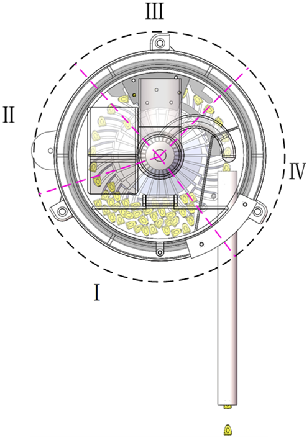
2.1. Overall Structure of the Seed Metering Device

The structure of the pneumatic-assisted guided seed-filling seed metering device for maize is illustrated in Figure 1. It primarily consists of an air inlet, a seed release guide tube, the left shell of the seed metering device, dual seed-cleaning blades, a seed-blocking plate, a conical deflector-groove seed metering disc, a mounting frame for the seed metering disc, a drive shaft, an airflow-blocking wheel, a seed-pushing wheel, the right shell of the seed metering device, seal, and seed guide tube.

2.2. Working Principle of the Seed Metering Device

The working process of the seed metering device is divided into four stages: seed filling, seed transport, seed cleaning, and seed release, as shown in Figure 2. In the seed filling stage, corn seeds enter the seed chamber through the seed inlet, and the seed-metering motor drives the seed metering disc to rotate clockwise via an elastic coupling. Positive pressure airflow enters the chamber of the seed metering device through the inlet of the same-source airflow-assisted seed release mechanism. After being diverted by the conical deflector-groove seed metering disc, the airflow pushes the seeds along the arc-shaped seed guide groove toward the metering holes. Ventilation holes at the bottom of the metering holes allow the seed layer to be guided and disturbed by the arc-shaped seed guide groove under static pressure, pressing the seeds onto the metering holes. The seeds then rotate along with the seed metering disc, completing the seed filling process. In the seed transport stage, the seeds are pressed against the metering holes by the positive airflow and rotate clockwise with the disc toward the seed cleaning area. In the seed cleaning stage, excess seeds on the metering holes are scraped off by the dual seed-cleaning blades and fall back to the seed filling area for re-filling. Single seeds continue along the seed guide channel of the dual seed-cleaning blades and move toward the seed release zone. In the seed release stage, the corn seeds rotate with the metering holes to the position above the airflow-blocking wheel. The airflow-blocking wheel interrupts the positive pressure airflow in the metering holes, and the airflow is redirected into the seed release guide tube. This generates an airflow thrust on the seeds, which, combined with gravity, propels them smoothly along the seed guide tube for uniform deposition into the seed furrow, completing the seed release and deposition process.

2.3. Design and Analysis of the Seed Metering Disc

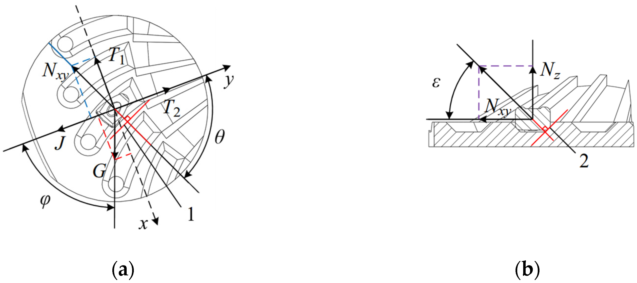
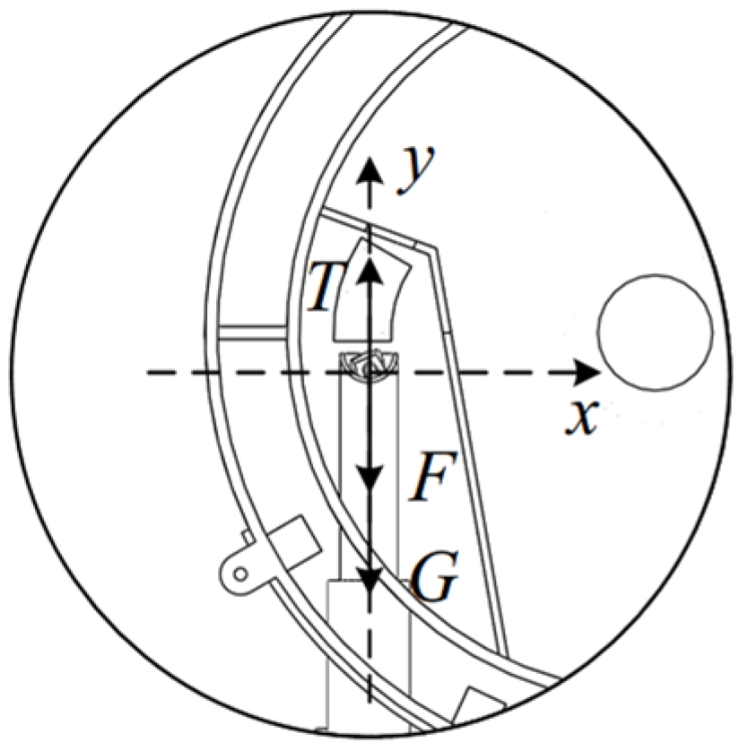
2.3.1. Force Analysis of Corn Seed Filling

High-speed seed metering operations significantly shorten the seed filling time compared to low-speed operations [19]. By combining seed guide groove disturbance with positive pressure assistance, the seed guide groove provides excellent guiding and disturbing effects, thereby enhancing the seed filling performance of the seed metering disc. The force analysis of seeds in the seed guide groove is shown in Figure 3.
The seeds in the seed guide groove are subject to gravity, support force, centrifugal force, resistance, and friction. The motion analysis of seeds in the xy plane is shown in Figure 3a.
m a 1 = N x y s i n θ + T 1 G s i n φ m a 2 = J + N x y c o s θ + G c o s φ T 2
where m is the mass of the seed in kg; a1 is the acceleration of the seed in the direction of the axis in m/s2; a2 is the acceleration of the seed in the direction of the axis in m/s2; Nxy is the support force of the seed by the seed guide trough in N; T1 is the seed resistance and friction in the x-axis direction of the force in N; T2 is the seed resistance and friction in the y-axis direction of the force in N; G is the seed gravity in N; J is the seed centrifugal force in N; θ is the xy-plane support and centrifugal force in the direction of angle in degrees; φ is the angle between the plane support force and the direction of centrifugal force in degrees.
As shown in Figure 3a, the angle θ between the support force and the centrifugal force in the xy plane is determined by the curvature of the seed guide groove. A smaller θ results in the greater acceleration of the seed in the negative y-axis direction, causing a tendency for movement in that direction. As illustrated in Figure 3b, when the seed moves along the negative y-axis, the support force generates a component force in the z-axis direction.
N z = N x y t a n ε
where Nz is the component of the support force in the z-axis direction in N and ε is the angle between the direction of the support force and the xy plane in degrees.
The force analysis in the xy plane indicates that as the seed metering disc rotates clockwise, the corn seeds within the seed guide groove move in the negative y direction. The point of support for the seeds in the guide groove shifts from a deeper to a shallower position. As the angle ε increases, the component of the support force in the z-axis direction (Nz) also increases, causing excess seeds to slide out along the edges of the seed guide groove. Based on the movement trajectory of the seeds, the seed guide groove should be designed with an arc-shaped profile.
During the seed filling process, the seed metering disc rotates at a constant angular velocity ω, and the seeds move along with the metering holes under the influence of airflow pressure. Due to inter-seed collisions and the vibrations of field machinery, a seed intake reliability factor and an external reliability factor need to be introduced [20]. A force analysis of the seeds at the metering holes is shown in Figure 4.
As shown in Figure 4, the corn seed at the metering hole is subjected to a resultant force F1, which includes air pressure F, the support force from the metering hole N, gravity, centrifugal force, and drag force. During the seed filling process, the forces acting on the seed are in equilibrium, and the moment at point A is zero, thus:
N x F f G s i n α = 0 N y J G c o s α = 0 N z F = 0 F L 1 F 1 L = 0
where Nx is the component of the supporting force acting on the seed in the x-axis direction in N; Ny is the component of the supporting force acting on the seed in the y-axis direction in N; Nz is the component of the supporting force acting on the seed in the z-axis direction in N; Ff is the drag force between the seeds in N; L1 is the vertical distance from the centre of gravity of the seed to point A in mm; L is the horizontal distance from the centre of gravity of the seed to point A in mm; α is the vertical angle between the line connecting the seed to the centre of the seed metering disc and the horizontal plane in degrees.
As shown in Figure 4a, the following can be obtained:
N x y = N x 2 + N y 2 J = m ω 2 r 1
where ω is the angular velocity of the disc in rad/s.
As shown in Figure 4b, the following can be obtained:
F 1 = N x y t a n β = L L 1
where β is the chamfer angle of the metering hole in degrees.
Solving Equations (3)–(5) simultaneously gives the solution.
F = F 1 L L 1 = N x y L L 1 = N x y t a n β
Rearranging the above equation gives the following:
F = F f 2 + 2 G F f s i n α + J c o s α + J 2 + G 2 t a n β
The relationship between the aerodynamic force F acting on the seed at the metering hole and the air pressure P at that point is as follows:
P = F S = F π L 1 2
where S is the cross-sectional area of the metering hole, in mm2.
Solving Equations (6)–(8) simultaneously yields the following:
P = L π L 1 3 F f 2 + 2 G F f s i n α + J c o s α + J 2 + G 2
Introducing K1 and K2 yields the following:
P = K 1 K 2 L π L 1 3 F f 2 + 2 G F f s i n α + J c o s α + J 2 + G 2
Since the metering hole diameter of the seed metering disc is relatively small, L1 can be approximated as half of the hole diameter, d.
L 1 = d 2
The stress analysis during the seed-filling stage indicates that, in the design of the seed metering disc, parameters such as air chamber pressure, seed mass, resistance and friction forces, disc rotational speed, disc diameter, and metering hole diameter must be carefully considered to ensure the optimal seed filling performance.

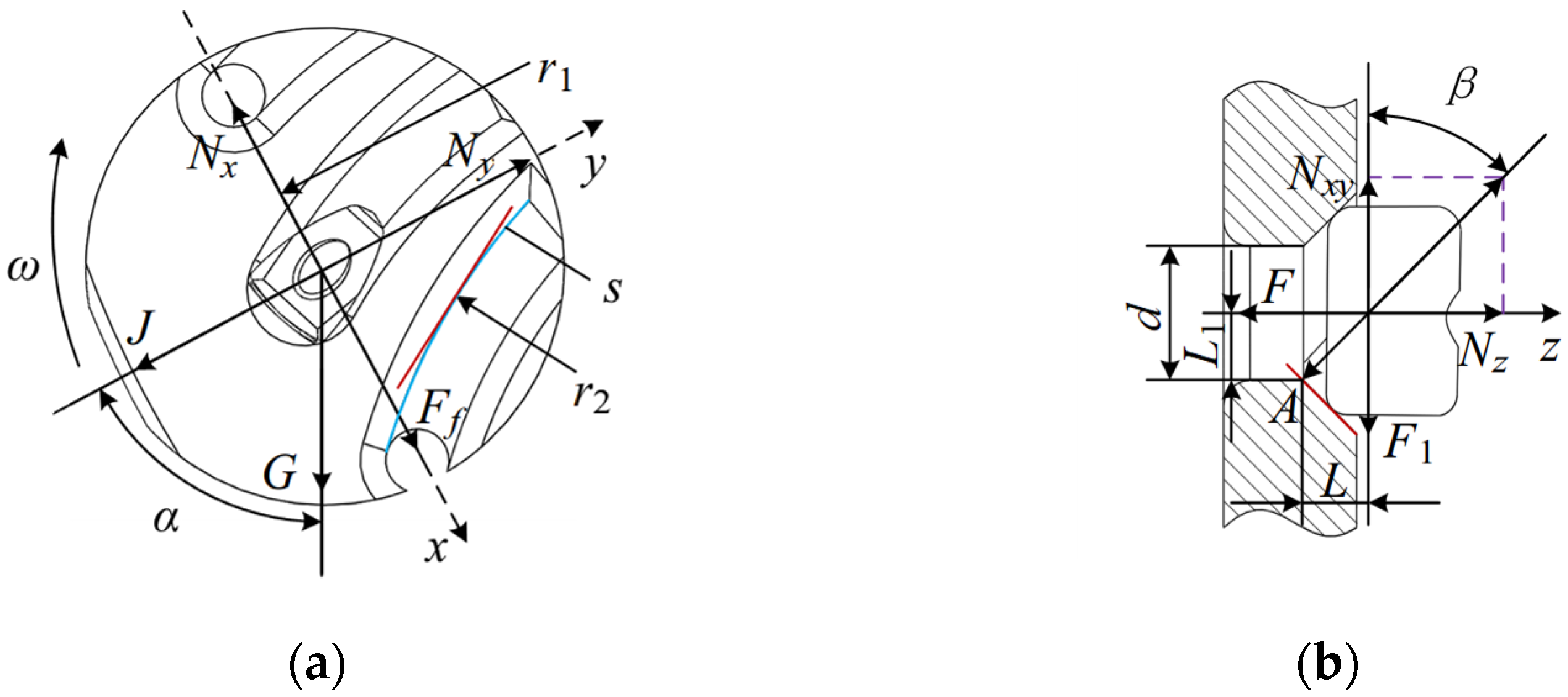
2.3.2. Metering Hole Design

The main structural parameters of the seed metering disc include the diameter of the seed metering holes, the distance between the centre of the holes and the centre of the disc, the number of seed metering holes, the width of the seed guide grooves, and the radius of the seed guide groove curves. The structure of the seed metering holes is shown in Figure 5. The seed metering holes near the inner side of the cavity are designed with conical guide grooves to increase the contact area between the holes and corn seeds during the filling process, enhancing seed coverage and reducing seed damage.
A total of 1000 uniform-sized and high-quality Jingke 968 corn seeds were randomly selected, and their average dimensions along the three axes were measured. The length a1, width b1, and thickness c1 were found to be 11.2 mm, 7.8 mm, and 5.0 mm, respectively. The pressure exerted on the seed by the metering hole is directly related to its diameter. The metering hole diameter d ranges from 0.64b to 0.66b [21], so the designed metering hole diameter d is 5.0 mm. Most corn seed metering discs have 26 metering holes [22]. Since the speed of the seed metering disc affects the centrifugal force experienced by the seeds during the filling process, the higher the speed, the greater the centrifugal force. To prevent seed loss due to excessive rotation speed, the speed of the seed metering disc should be reduced as much as possible, and the number of metering holes should be as large as possible [23]. Referring to the number of holes in seed metering discs both domestically and internationally, the number of metering holes z1 in the seed metering disc was determined to be 27.
The relationship between the rotational speed of the seed metering disc and the forward speed of the machine is as follows:
v m = L z z 1 n z
where vm is the forward speed of the machine in m/s; Lz is the corn planting spacing for precision seeding in m; nz is the rotational speed of the seed metering disc in r/min.
The relationship between the rotational speed of the seed metering disc and the linear speed at the metering hole is as follows:
n z = 30 v π r 1
where v is the linear speed of the metering hole in m/s and r1 is the distance between the centre of the metering hole and the centre of the seed metering disc in m.
From Equations (12) and (13), we can derive the following:
v m = 30 L z z 1 v π r 1
The distance between the centre of the metering hole and the centre of the seed metering disc should satisfy the following:
r 1 D 2
As can be seen from Equation (14), the linear velocity of the metering hole is related to the forward speed of the machine. As the forward speed increases, the linear velocity of the metering hole also increases. For high-speed precision corn seeding, the forward speed typically ranges between 8 and 12 km/h. To accommodate this, the forward speed vm is set to 12 km/h, and the corn planting spacing Lz is set to 20 cm. According to the literature [24], the diameter of the seed metering disc in pneumatic seed metering devices generally ranges from 140 to 260 mm. Considering the structural constraints of the seed metering device housing, the disc diameter D is selected to be 180 mm. Substituting it into Equation (15), the distance r1 between the centre of the metering hole and the centre of the seed metering disc is calculated to be ≤90 mm. To ensure a proper clearance between the outer edge of the metering hole and the disc edge, r1 is set to 70 mm.
During the seed-filling process, one side of the corn seed should be fully embedded in the seed release guide groove. Following the principle that seeds should move smoothly within the seed guide groove, and based on the measured width of the corn seeds, the width of the seed guide groove is determined to be 9.0 mm. To ensure proper seed movement during the filling process, and considering the measured average length of the seeds, the arc length of the seed guide groove is set to 21.5 mm, with a curvature radius r2 of 50 mm.

2.3.3. Tapered Seed Guide Groove Design of the Seed Metering Disc

The primary structural parameters of the conical deflector-groove in the seed metering disc include the radius r4, height h1, and the number of deflector-grooves z2. Figure 6 shows a stress analysis of the maize seeds at the edge of the deflector-groove.
The conical deflector-groove seed metering disc features circumferentially distributed bosses in the middle, as shown in Figure 6. According to the continuity equation, fluid velocity is inversely proportional to the cross-sectional flow area. As the airflow enters the chamber of the seed metering device and flows past the bosses, the cross-sectional flow area decreases, leading to an increase in flow velocity [25]. This increased velocity enhances kinetic energy while reducing static pressure. Consequently, the pressure on the seeds at the edges of the deflector-grooves decreases, along with inter-seed resistance and friction, facilitating easier seed movement.
Seeds that fall to the edge of the deflector-groove contact one side of the seed guide groove. At this point, the seeds are subjected to the combined effects of gravity, support force, centrifugal force, drag, friction, and airflow thrust, causing them to move toward the seed guide groove. The seed movement is analysed in the xy plane, as shown in Figure 6a.
m a 1 = N x y s i n δ + T 1 G s i n σ m a 2 = J + N x y c o s δ + G c o s σ + F P y T 2
where FP is the thrust of the airflow on the seed in N; FPy is the component of the airflow thrust in the xy plane in N; δ is the angle between the support force and the direction of the centrifugal force in the xy plane in degrees; σ is the angle between the gravitational force and the direction of the centrifugal force in the xy plane in degrees.
As shown in Figure 6b, in the z-plane, the seed moves towards the seed guide groove under the influence of the airflow thrust FP. The horizontal force acting on it is:
F P y = F P c o s ζ
where ζ is the angle between the direction of the airflow thrust in the z plane and the xy plane, in degrees.
From the force analysis in the xy plane, it is evident that the corn seed moves along the negative y-axis under the influence of the airflow thrust FP and enters the seed guide groove. Based on Equations (16) and (17), it can be deduced that:
m a 2 = J + N x y c o s δ + G c o s σ + F P c o s ζ T 2
From Equation (18), it is evident that the magnitude of the radial airflow thrust FPy on the corn seed is influenced by the angle ζ. A smaller ζ results in a greater radial airflow thrust, which facilitates seed movement during the filling and enhances the filling efficiency. Therefore, minimising ζ is beneficial. Additionally, the height of the deflector-groove h1 is related to the chamber thickness. To avoid excessive energy loss due to an overly thick chamber, the deflector-groove height h1 is set to 15 mm.
It is known that the diameter d of the seed metering disc is 180 mm, the radius r3 is 90 mm, the distance r1 between the centre of the metering hole and the centre of the seed metering disc is 70 mm, and the equivalent radial length l of the seed guide groove in the seed metering disc is 21.35 mm. Therefore, the radius of the deflector-groove should satisfy the following:
r 4 + l r 1
Equation (19) yields r4 ≤ 48.65 mm. Considering the installation position of the deflector-groove, the deflector-groove radius r4 is set to 48 mm. The angle ζ is determined to be 25° based on the deflector-groove height and radius. It is known that the seed metering disc has 27 circumferential metering holes (z1 = 27), and the number of metering holes, seed guide grooves, and deflector-grooves must correspond. Therefore, the number of deflector-grooves z2 is also set to 27.

2.4. Design and Analysis of the Same-Source Airflow-Assisted Seed Release Mechanism

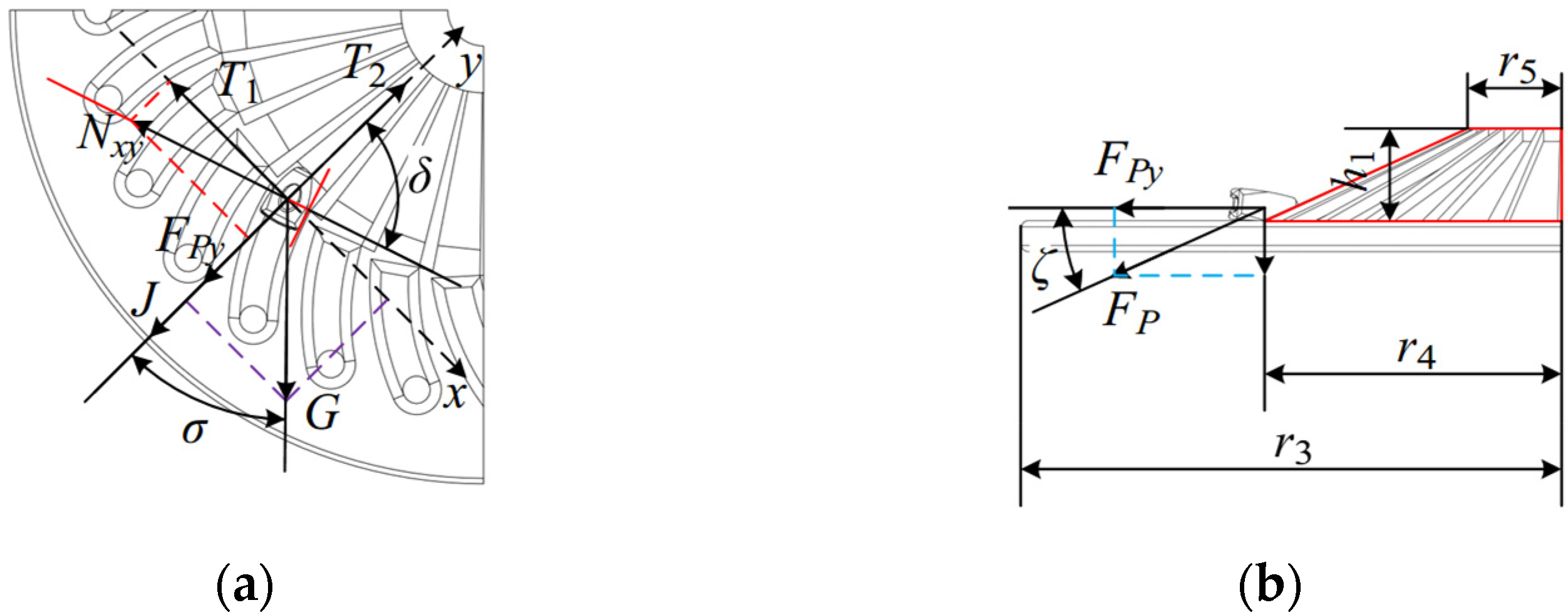
2.4.1. Force Analysis of Seeds in the Seed Release Process

The same-source airflow-assisted seed release mechanism, installed on the left housing of the seed metering device, is a critical component for ensuring the successful filling, transportation, and transfer of seeds through the seed guide tube via the positive pressure of airflow within the chamber. As shown in Figure 7, corn seeds enter the chamber of the seed metering device through the seed inlet. A seed-blocking plate located on one side of the chamber guides the seeds during filling and prevents them from piling up or moving chaotically. A portion of the positive pressure airflow enters the chamber through the air inlet to facilitate seed filling, while another portion flows into the seed release guide tube, acting on the corn seeds within the tube to assist in seed intake.
During the seed release process, the positive pressure airflow at the metering hole is obstructed by the airflow-blocking wheel, causing the corn seeds to fall into the seed guide tube under the combined effects of gravity and airflow thrust. The stress analysis of the corn seeds during the seed release process is illustrated in Figure 8.
The force analysis of the seeds during the seed release process in the vertical direction is shown in Figure 8.
F + G T = m a
where F is the airflow thrust acting on the seed in N; T is the collision resistance acting on the seed in N; a is the acceleration of the seed’s motion in m/s2.
From Equation (20), it is clear that the seed’s acceleration, a, is directly proportional to the airflow thrust, F, acting on the seed. In other words, an increase in airflow thrust leads to a corresponding increase in the seed’s acceleration.

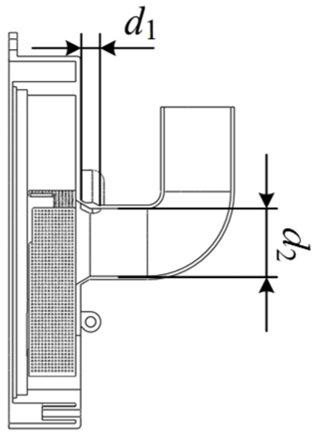
2.4.2. Design and Analysis of the Air Inlet

The structure of the air inlet is shown in Figure 9. Its main structural parameters include the diameter of the seed release guide tube, d1, and the diameter of the air inlet, d2.
The relationship between the airflow thrust and the pressure in the seed release guide tube is:
P c = F c S 1 = 4 F c π d 1 2
where Fc is the airflow thrust in the seed release guide tube in N; Pc is the pressure in the cross-section of the seed release guide tube in Pa; d1 is the diameter of the seed release guide tube in m; S1 is the cross-sectional area of the seed release guide tube in m2.
The magnitude of the airflow thrust acting on the seed during the seed release process is as follows:
F = P S 2 = π d 2 2 P 4
where F is the airflow thrust acting on the seed in N; P is the pressure acting on the seed in Pa; d2 is the equivalent diameter of the seed in m; S2 is the equivalent cross-sectional area of the seed in m2.
Solving Equations (20)–(22) simultaneously provides the following solution:
m g + π d 2 2 P 4 T = m a
From Equation (23), it is evident that the acceleration of the seed’s movement, a, is directly proportional to the pressure P acting on the seed. Specifically, a higher pressure results in a greater airflow thrust on the seed. Equations (21) and (22) indicate that the magnitude of the airflow thrust F on the seed is positively correlated with the cross-sectional pressure Pc of the seed release guide tube. A higher pressure leads to a greater airflow thrust on the seed. The cross-sectional pressure Pc of the seed release guide tube is inversely related to its diameter d1; a larger diameter results in a lower cross-sectional pressure. To maximise the airflow thrust on the seeds, the diameter of the seed release guide tube should be minimised. Additionally, to reduce the energy loss during the seed release process, uniform force application to the seeds is essential. Based on the measured seed size, the diameter of the seed release guide tube d1 is determined to satisfy d1a1, and is set to 12 mm.
After considering the structural dimensions of the seed metering device housing and the diameter of the air blower intake pipe, the air inlet diameter d2 was determined to be 40 mm. The air inlet is positioned centrally within the housing to ensure even airflow distribution into the chamber.

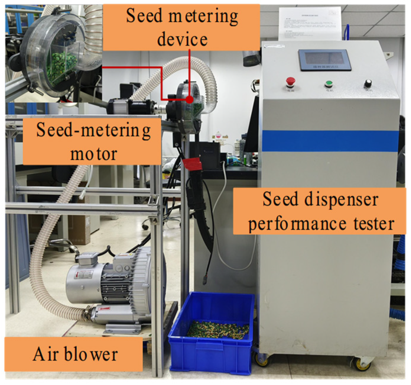
2.5. Performance Bench Experiment of the Seed Metering Device

2.5.1. Preparation of Experiment Materials

The test used Beijing Science 968 corn seeds, which are widely cultivated in the Huang-Huai-Hai region. The seed moisture content was 12.8%, and the thousand-grain weight was 351 g. The average dimensions of the seeds along the three axes were 11.2 mm, 7.8 mm, and 5.0 mm, respectively. Prior to testing, the corn was properly screened and thoroughly mixed to ensure the sample’s representativeness. A prototype pneumatic seed metering device was developed for this study. The seed metering disc was made using 3D-printed nylon material. Nylon material exhibits excellent temperature resistance, high toughness, and strength, along with robust mechanical properties. It features a minimum wall thickness of 0.8 mm and precision machinability, making it well-suited for use as a seed metering disc. The housing on the air inlet side was constructed from transparent resin to facilitate observation. Transparent resin combines high strength and hardness with a smooth surface, a minimum wall thickness of 0.5 mm, and precision machinability. When used as a housing material, it enables clear observation of seed dynamics, particularly at the different stages of seed metering. The finished seed metering device is shown in Figure 10. Preliminary functional tests confirmed that the seed metering device essentially meets the operational requirements.
The test bench is built on the basis of the Huai yu N288 type seed metering device performance tester, this tester is manufactured by Changzhou Huaiyu Electronics Co. (Changzhou, China) which can measure performance indicators such as the qualified seed spacing index, missed sowing index, and resowing index in real time. The tester is equipped with a photoelectric sensor for precise seed drop detection, ensuring a high measurement accuracy. It allows flexible configuration of sowing parameters: the plant spacing range is 10–35 cm, the metering hole count ranges from 6 to 40, and the seed target count can be set from 0 to 9999. The test bench uses an RB-51D-4 variable frequency air blower to provide the air supply, this equipment was manufactured by Jiangsu Quanfeng Environmental Protection Technology Co. (Wuxi, China). After the frequency adjustment, the air blower can provide a stable air source ranging from 0 to 5 kPa, meeting the requirements of the seeding operation. The test bench utilises the German Testo 440 anemometer to measure the air pressure., the instrument was manufactured by Dettol Instruments International Trading Co. (Shanghai, China). During the measurement, the Pitot tube of the anemometer is connected to the air blower inlet pipe. The anemometer is activated first, followed by the seed-metering motor and the air blower, aiming to measure the working wind pressure when the seed metering device operates stably. The test bench utilises a brushless servo motor to drive the seed metering device. The motor is equipped with a driver and a controller, which adjusts the rotational speed of the seed metering device via a knob. This setup enables the seed metering device to operate at different rotational speeds, aligning with actual sowing operation speeds. When stopping the operation, the air blower should be turned off first, followed by disconnecting the power supply to the seed-metering motor. The model parameters of the test bench are shown in Table 1.
The main test equipment includes the following: air blower, seed-metering motor, pneumatic-assisted guided seed-filling seed metering device, and seed dispenser performance tester. The main test setup includes an air blower, a seed-metering motor, a pneumatic-assisted guided seed-filling seed metering device, and a seed metering device performance tester. The air inlet pipe of the air blower is connected to the air inlet of the seed metering device, while the seed-metering motor and the seed metering device are securely mounted on a test bench. The seed metering test bench is shown in Figure 11.

2.5.2. Experiment Method

According to GB/T 6973-2005 “Test Methods for Single-Seed (Precision) Planters”, the operating speed and working pressure were selected as test factors, with the qualified seed spacing index, missed sowing index, resowing index, and coefficient of variation in qualified seed spacing as performance indicators.
The qualified seed spacing index is a key metric for evaluating the seed metering accuracy of the planter. It reflects the proportion of seed spacings that meet the predetermined requirements and is calculated as follows:
X 1 = M 1 N × 100 %
where X1 represents the qualified seed spacing index (%), M1 denotes the number of seed spacings that meet the specified criteria, and N is the total number of seed spacings.
The missed sowing index quantifies the extent of missed sowing during the test and is calculated as follows:
X 2 = M 2 N × 100 %
where X2 represents the missed sowing index (%), M2 denotes the number of missed sowing intervals, and N is the total number of seed spacings.
The resowing index quantifies the occurrence of multiple seed drops at the same sowing position during the test, representing the proportion of such instances. It is calculated as follows:
X 3 = M 3 N × 100 %
where X3 represents the resowing index (%), M3 denotes the number of resowing intervals, and N is the total number of seed spacings.
The coefficient of variation for the qualified seed spacing is used to quantify the uniformity of seed spacing. A lower coefficient of variation indicates a more consistent seed placement. The coefficient of variation for the qualified seed spacing is determined as follows:
X 4 = σ 1 P 1 × 100 %
where X4 is the coefficient of variation for the qualified seed spacing, (%); σ1 is the standard deviation of seed spacing; and P1 is the mean of seed spacing.
Data collection and statistical analysis can be performed using the seed dispenser performance tester, model Huaiyu N288. This tester is equipped with photoelectric sensors to detect seed drops in real time. The test bench allows for adjustable plant spacing from 10 to 35 cm, metering hole settings from 6 to 40, and a seeding target range from 0 to 9999. Before the test, the seed dispenser performance tester is activated, and parameters such as target seeding quantity, target seed spacing, seed metering disc speed, and number of metering holes are set. At the start of the test, the air blower and seed-metering motor are switched on, allowing the tester to display various performance indicators in real time, including the total number of seeds sown, the qualified seed spacing index, missed sowing index, resowing index, average seed spacing, and seed spacing variance. Once the total number of seeds sown reaches the preset target, data collection on the tester stops. At this point, the qualified seed spacing index, missed sowing index, and resowing index can be directly obtained. Additionally, the coefficient of variation in qualified seed spacing can be calculated using the standard deviation and mean seed spacing.
The operating speed was set from 6 to 12 km/h in 2 km/h increments. The working pressure was set from 2 to 5 kPa in 1 kPa increments. Each test was repeated three times, with 251 seed measurements collected per trial. The average values from the three trials were used for statistical analysis. The experimental factors and their levels are shown in Table 2.

3. Results and Discussion

3.1. Test Bench Results and Discussion

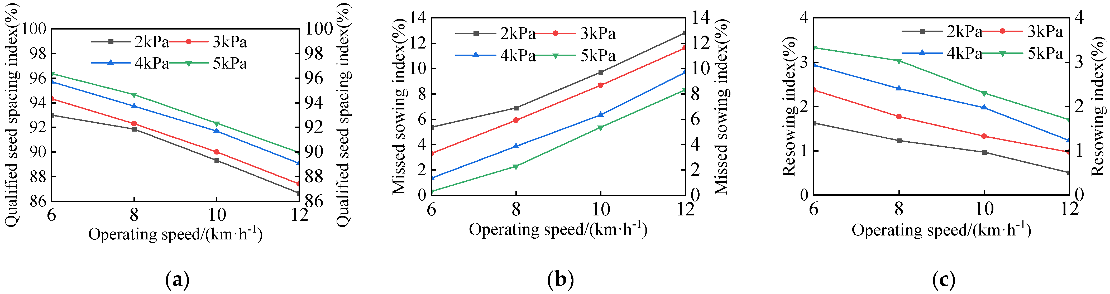
3.1.1. Test Bench Results

Statistical analysis was performed on the qualified seed spacing index, missed sowing index, resowing index, and coefficient of variation in qualified seed spacing. The test results are shown in Table 3.
The test results were imported into Origin for the processing and analysis, and the results are shown in Figure 12.

3.1.2. Discussion of Test Bench Results

As shown in Figure 12, the qualified seed spacing index was consistently the highest at a working pressure of 5 kPa and lowest at 2 kPa. As the operating speed increases, both the qualified seed spacing index and the resowing index exhibited a downward trend, while the missed sowing index showed an upward trend. At an operating speed of 6 km/h, increasing the working pressure from 2 kPa to 3 kPa, 4 kPa, and 5 kPa resulted in a decrease in the missed sowing index and an increase in the resowing index. When the operating speed gradually increased from 6 km/h to 8 km/h, 10 km/h, and 12 km/h, the qualified seed spacing index decreased significantly, indicating that the operating speed had a substantial impact on seed metering quality.
When the seeding operation speed is 6 km/h and the working pressure ranges from 2 to 5 kPa, the qualified seed spacing index of the seed dispenser is at least 93.0%, the missed sowing index is below 5.37%, the resowing index is below 3.33%, and the coefficient of variation for qualified seed spacing does not exceed 20.07%. At an operation speed of 8 km/h and a working pressure of 2 to 5 kPa, the qualified seed spacing index is at least 91.87%, the missed sowing index is below 6.90%, the resowing index is below 3.03%, and the coefficient of variation for qualified seed spacing does not exceed 21.33%. At an operation speed of 10 km/h and a working pressure of 2 to 5 kPa, the qualified seed spacing index is at least 89.33%, the missed sowing index is below 9.70%, the resowing index is below 2.30%, and the coefficient of variation for qualified seed spacing does not exceed 22.33%. At an operation speed of 12 km/h and a working pressure of 2 to 5 kPa, the qualified seed spacing index is at least 86.67%, the missed sowing index is below 12.83%, the resowing index is below 1.70%, and the coefficient of variation for qualified seed spacing does not exceed 24.47%.
The optimal parameter combination for the bench test was an operating speed of 6 km/h and a working pressure of 5 kPa. Under these conditions, the qualified seed spacing index was 96.37%, the missed sowing index was 0.30%, the resowing index was 3.33%, and the coefficient of variation for qualified seed spacing was 17.37%. According to «NY/T 503-2015 Single-Grain (Precision) Planter Operation Quality», when the seed spacing is set at 20 cm, the operational quality requirements are as follows: the qualified particle spacing index should be no less than 70.0%, the missed sowing index must not exceed 22.0%, the resowing index should be below 17.0%, and the coefficient of variation for qualified particle spacing must remain under 38.0%. All indicators met the technical requirements for precision single-seed corn sowing.

3.2. Field Seeding Test

3.2.1. Materials and Methods for Field Test

To evaluate the performance of the pneumatic-assisted seed metering device under high-vibration conditions, field seeding tests were conducted, as shown in Figure 13. The test prototype was a high-speed air-blown planter produced by Deyi Bo Agricultural Machinery Co., Ltd., Anyang, China. The target seed was Jingke 968 corn, and the test was powered by a John Deere 904 tractor. The length of the test plot was approximately 100 m.
Referring to the working parameter range established during the bench test and considering the significant vibrations encountered by the seed metering device during field operations, a single-factor test was conducted by setting the air blower’s working pressure to 5 kPa and varying the seed metering device’s operating speed across four levels: 6 km/h, 8 km/h, 10 km/h, and 12 km/h. The seed metering disc is driven by a ground wheel, with the target seed spacing set to 20 cm. This corresponds to seed metering disc speeds of 18.53 r/min, 24.66 r/min, 30.86 r/min, and 37.04 r/min, respectively. According to GB/T 6973-2005 “Test Methods for Single-Seed (Precision) Planters”, a 10 × 5 m sampling section is selected within the working area, and no fewer than 251 seeds are measured for each test, as shown in Figure 13b. After the sowing is completed, the test data are obtained by excavating the seeds. The distribution of the seeds in the furrow is illustrated in Figure 13c. Each group of tests is repeated three times, and the average of the three trials is used as the final test result.

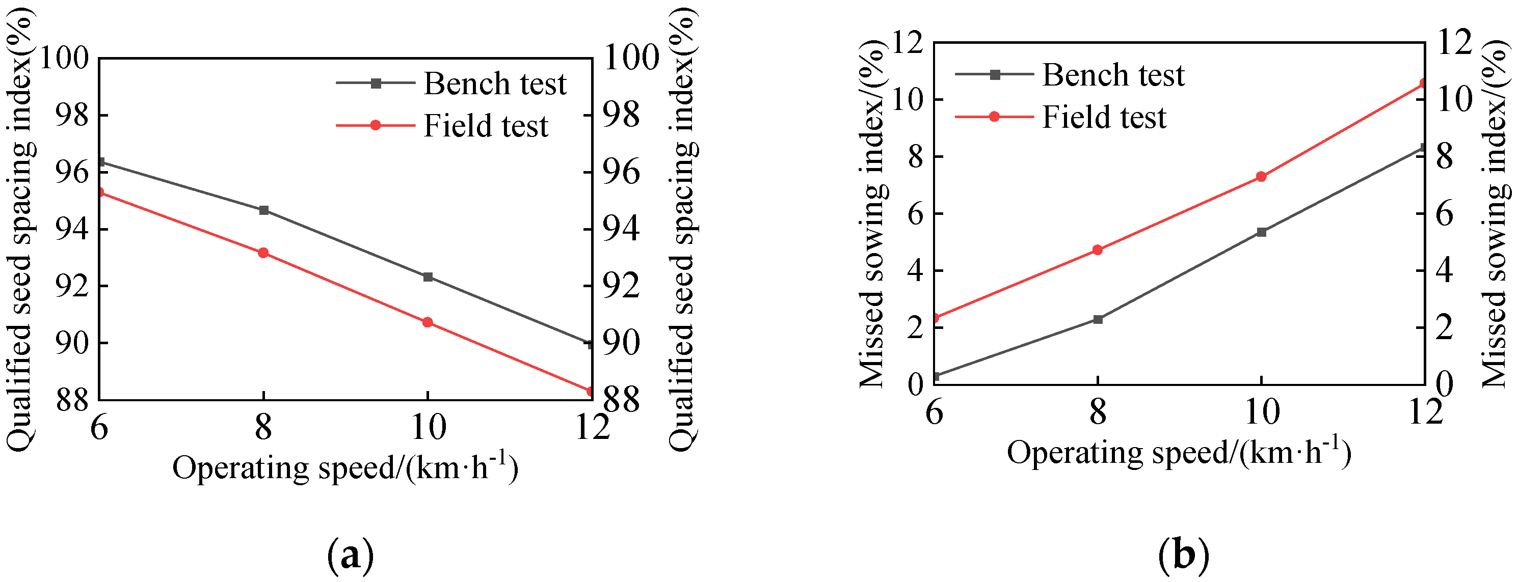
3.2.2. Field Test Results and Discussion

Statistical analysis was performed on the qualified seed spacing index, missed sowing index, and resowing index. The field test results are shown in Table 4.
As shown in Table 4, at an operating speed of 6 km/h and a working pressure of 5 kPa, the qualified seed spacing index was 95.30%, the missed sowing index was 2.33%, and the resowing index was 2.37%. These results comply with the requirements for precision sowing technology.
A comparison of the field test results and the bench test results are shown in Figure 14.
As illustrated in Figure 14, under operating speeds of 6 km/h, 8 km/h, 10 km/h, and 12 km/h, with a working pressure of 5 kPa, the missed sowing index in the field test increased significantly compared to the bench test, while the qualified seed spacing index decreased, resulting in a decline in sowing quality.
Compared with traditional mechanical seed metering devices reported in the literature [3,9,10,11,12], this design optimises the structure of the seed metering disc and the airflow path, enabling seeds to be more uniformly adsorbed onto the metering holes under positive pressure. This optimisation improves seed filling accuracy and enhances overall operational stability. Compared with the air-suction-based seed metering device described in the literature [8], this design employs a positive-pressure-assisted method, which is less susceptible to external environmental disturbances. Additionally, the refined deflector-groove structure regulates airflow, reducing fluctuations in seed collision speed at the seed guide tube and effectively preventing seed accumulation, thereby improving seeding uniformity. Compared with pneumatic seed metering devices discussed in the literature [16,17], this pneumatic-assisted guided seed-filling seed metering device effectively alleviates missed sowing and resowing issues caused by seed population disturbance and airflow fluctuation during high-speed operation. This is achieved through the introduction of positive-pressure assistance technology and a unique, same-source airflow-assisted seed release mechanism during the seed filling and delivery process. Overall, this study not only overcomes the limitations of traditional seeding devices under high-speed operation conditions but also provides a valuable technical pathway for the advancement of precision seeding technology.
In this study, by optimising the seed filling and release processes, the seed metering accuracy and operational stability were significantly improved. According to preliminary test results, under optimal operating parameters, the qualified seed spacing index of the seed metering device developed in this study reached 96.37%, showing a notable increase compared to the 92.83% reported for the mechanical seed metering device in the literature [3] and a significant improvement over the 95.8% reported for the air-suction-based seed metering device in the literature [8]. Additionally, the missed sowing index was significantly reduced.
The increase in productivity, along with a higher work rate per unit area, is expected to significantly shorten seeding duration and expand the cultivated area. It is estimated that seed cost could be reduced by 5% to 10% in large-scale seeding operations. Considering the economic benefits of increased productivity and reduced seed cost, the seeding cost per unit area is anticipated to decrease substantially. In the future, integrating smart monitoring and control systems could allow real-time adjustments to the equipment’s operating status, enabling adaptation to varying field conditions and operational requirements, thereby further enhancing economic benefits.
However, this study has certain limitations. First, during the field experiment, due to uneven soil surfaces and significant variations in field conditions, large vibrations and speed fluctuations may occur during the actual operation of the seed metering device. These factors may introduce testing deviations, leading to discrepancies between experimental data and the ideal conditions. For instance, seeds may shift or even dislodge during the seed filling or seed release stages of the seed metering disc, resulting in missed sowing. Second, the findings of this study are based on the operating speeds and working pressures determined under specific test conditions, which may limit the applicability of the results to different environmental conditions. Additionally, external factors such as wind speed, temperature, humidity, and soil moisture content may also influence seed metering performance. Therefore, while this study elucidates the primary causes of missed sowing, the complexity of real-world field conditions requires careful consideration. Future studies should refine experimental designs, expand the parameter range, and validate the results under more stringent field conditions to enhance the generalizability and reliability of the findings.

4. Conclusions

(1) An auxiliary air-assisted seed-filling pneumatic corn planter has been designed to address the decline in the qualified seed spacing index during high-speed operation of the pneumatic corn planter. The conical deflector-groove seed metering disc and the same-source airflow-assisted seed release mechanism facilitated seed movement during the seed filling and seed release stages, thereby enhancing seed metering performance.
(2) Based on the stress analysis of the seed filling and seed release stages, the key structural parameters of the conical deflector-groove seed metering disc and the same-source airflow-assisted seed release mechanism were calculated. The critical dimensions and parameters of the metering holes, seed metering disc, seed guide groove, deflector-groove, seed release guide tube, and air inlet were determined.
(3) The optimal parameter combination for the bench test was an operating speed of 6 km/h and an operating pressure of 5 kPa. Under these conditions, the qualified seed spacing index was 96.37%, the missed sowing index was 0.30%, the resowing index was 3.33%, and the coefficient of variation for the qualified seed spacing was 17.37%. Field test results indicated that at an operating speed of 6 km/h and a working pressure of 5 kPa, the qualified seed spacing index was 95.30%, the missed sowing index was 2.33%, and the resowing index was 2.37%. All indicators met the technical requirements for precision single-seed maize planting.
(4) Compared with the existing seed metering devices, the conical deflector-groove seed metering disc and same-source airflow-assisted seed release mechanism designed in this study improved the seed filling and seed release performance. Under optimal operating parameters, the qualified particle spacing index of the developed seed metering device reached 96.37%, demonstrating a significant improvement over the traditional mechanical seed metering devices and a notable enhancement compared to some pneumatic-suction-based seed metering devices. Furthermore, the missed sowing index was significantly reduced.

Author Contributions

Conceptualization, J.Y. and G.W.; methodology, J.Y. and G.W.; validation, J.Y., B.Y. and R.L.; formal analysis, L.L.; resources, B.Y.; data curation, J.Y. and G.W.; writing—original draft preparation, J.Y. and B.Y.; writing—review and editing, J.Y., Y.X. and J.G.; visualisation, J.Y.; supervision, G.W.; project administration, B.Y.; funding acquisition, G.W. All authors have read and agreed to the published version of the manuscript.

Funding

The APC was funded by the China National Key R&D Program (2021YFD2000405-3), the China Ministry of Finance and Ministry of Agriculture and Rural Development: National Modern Agricultural Industrial Technology System Project (CARS-02).

Institutional Review Board Statement

The study did not require ethical approval.

Data Availability Statement

The data presented in this study are available on request from the corresponding author. We have committed to providing all relevant data promptly upon the official publication of the article and ensuring that the data are accessible in accordance with the journal’s requirements. Thank you for your understanding and support. For further information about the data, please contact Jiahua Yan at jiahua_yan@outlook.com.

Acknowledgments

The authors would like to thank the anonymous reviewers for their constructive comments, which helped improve the quality of this paper.

Conflicts of Interest

The authors declare no conflicts of interest.

References

  1. Yang, L.; Yan, B.X.; Zhang, D.X.; Zhang, T.L.; Wang, Y.X.; Cui, T. Research progress of precision seeding technology for corn. J. Agric. Mach. 2016, 47, 38–48. [Google Scholar]
  2. Yuan, Y.; Bai, H.; Fang, C.; Wang, D.; Zhou, L.; Niu, K. Research progress of corn seeding and measurement and control technology. J. Agric. Mach. 2018, 49, 1–18. [Google Scholar]
  3. Guo, J.; Yang, Y.; Memon, M.S.; Tan, C.; Wang, L.; Tang, P. Design and simulation for seeding performance of high-speed inclined corn metering device based on discrete element method (DEM). Sci. Rep. 2022, 12, 19415. [Google Scholar]
  4. Tang, H.; Xu, C.; Wang, Z.; Wang, Q.; Wang, J. Optimized Design, Monitoring System Development and Experiment for a Long-Belt Finger-Clip Precision Corn Seed Metering Device. Front. Plant Sci. 2022, 13, 814747. [Google Scholar] [CrossRef]
  5. Hörbe, T.A.N.; Amado, T.J.C.; Reimche, G.B.; Schwalbert, R.A.; Santi, A.L.; Nienow, C. Optimization of Within-Row Plant Spacing Increases Nutritional Status and Corn Yield: A Comparative Study. Agron. J. 2016, 108, 1962–1971. [Google Scholar] [CrossRef]
  6. Ding, L.; Yang, L.; Zhang, D.X.; Cui, T.; Zhang, K.L.; Zhong, X.J. Analysis of the effect of adsorption attitude on seed delivery performance of air-absorbing corn seed discharger. J. Agric. Mach. 2021, 52, 40–50. [Google Scholar]
  7. Chen, J.; Guan, T.; Yuan, Z.; Xu, F.; Zhao, K.; Tang, H.; Zhao, J.; Wang, J. Development of high-speed precision maize metering device for dense planting pattern with standard ridges. Front. Plant Sci. 2024, 15, 1452699. [Google Scholar] [CrossRef]
  8. Ding, L.; Yuan, Y.; Dou, Y.; Li, C.; He, Z.; Guo, G.; Zhang, Y.; Chen, B.; Li, H. Design and Experiment of Air-Suction Maize Seed-Metering Device with Auxiliary Guide. Agriculture 2024, 14, 169. [Google Scholar] [CrossRef]
  9. Xiong, D.; Wu, M.; Xie, W.; Liu, R.; Luo, H. Design and Experimental Study of the General Mechanical Pneumatic Combined Seed Metering Device. Appl. Sci. 2021, 11, 7223. [Google Scholar] [CrossRef]
  10. Baghooee, M.; Karparvarfard, S.H.; Azimi-Nejadian, H.; Keramat-Jahromi, M.; Balanian, H.; Sardarpour, F. DEM Simulation for Seeding Performance of a Slotted Roller Seed-Metering Device for Planting Maize in Laboratory Condition. J. Biosyst. Eng. 2023, 48, 428–436. [Google Scholar] [CrossRef]
  11. Jiang, X.; Zhang, J.; Liu, S.; Fu, L.; Huang, D. Development and Evaluation of a Universal Seed Discharger for Precision Planting in Corn-Soybean Cropping System. Processes 2024, 12, 1595. [Google Scholar] [CrossRef]
  12. Liu, H.; Jia, R.; Zhou, X.; Fu, L. Virtual assembly of man-machine interactive mechanical seed-metering device based on matter-element identification. Trans. Chin. Soc. Agric. 2016, 32, 38–45. [Google Scholar]
  13. Tang, H.; Guan, T.; Xu, F.; Xu, C.; Wang, J. Test on adsorption posture and seeding performance of the high-speed precision dual-chamber maize metering device based on the seed characteristics. Comput. Electron. Agric. 2024, 216, 108471. [Google Scholar]
  14. He, X.; Wan, Y.; Zhong, P.; Lin, J.; Huang, M.; Yang, R.; Zang, Y. Design and experimental analysis of real-time detection system for The seeding accuracy of rice pneumatic seed metering device based on the improved YOLOv5n. Comput. Electron. Agric. 2024, 227, 109614. [Google Scholar]
  15. Li, Q.L.; Yu, J.Y.; Zhang, Q.Q.; Yu, J.Q.; Fu, H. Simulation Analysis of the Working Process of the Corn Seed Metering Device with Combination Inner-Cell. Appl. Mech. Mater. 2012, 215–216, 160–167. [Google Scholar] [CrossRef]
  16. Shi, S.; Zhang, D.; Yang, L.; Cui, T.; Zhang, R.; Yin, X. Design and test of pneumatic combined hole type corn precision seed discharger. J. Agric. Eng. 2014, 30, 10–18. [Google Scholar]
  17. Yang, S.D.; Zhang, D.X.; Gao, Z.Q.; Liu, X.Q. Simulation and test of flow field of lateral positive pressure corn seed discharger. J. Agric. Mach. 2014, 45, 35–39. [Google Scholar]
  18. Sun, W.S.; Yi, S.; Qi, S.J.; Qi, H.L.; Wang, S.; Li, Y.F.; Dai, Z.B. Research on double-disk staggered pneumatic pressure type high-speed precision seed discharger for zigzag dense planting of corn. J. Agric. Mach. 2024, 55, 168–179. [Google Scholar]
  19. Guo, P.; Zheng, X.-S.; Wang, D.-W.; Hou, J.-L.; Zhao, Z. Design and test of pneumatic-assisted seed filling type peanut precision seed discharger. J. Agric. Mach. 2024, 55, 64–74. [Google Scholar]
  20. Yan, B.X.; Zhang, D.X.; Cui, T.; He, X.; Ding, Y.; Yang, L. Design of pneumatic suction corn precision seed discharger with synchronized rotation of seed disks and negative pressure chambers. J. Agric. Eng. 2017, 33, 15–23. [Google Scholar]
  21. Ding, L.; Yang, L.; Wu, D.H.; Li, D.Y.; Zhang, D.X.; Liu, S.R. Simulation and test of corn air suction seed discharger based on DEM-CFD coupling. J. Agric. Mach. 2018, 49, 48–57. [Google Scholar]
  22. Ding, L.; Yang, L.; Liu, S.R.; Yan, B.X.; He, X.T.; Zhang, D.X. Design of air-aspirated high-speed precision seed discharger for corn with auxiliary seed-filling disc. J. Agric. Eng. 2018, 34, 1–11. [Google Scholar]
  23. Lai, H. Design and Testing of a Pneumatic Cone Disc Precision Spaced Planter for Wide Wheat Seedlings. Master’s Thesis, Huazhong Agricultural University, Wuhan, China, 2023. [Google Scholar]
  24. Chinese Academy of Agricultural Mechanization Sciences. Handbook of Agricultural Machinery; China Agricultural Science and Technology Press: Beijing, China, 2007. [Google Scholar]
  25. Zheng, J.; Lai, H.; Li, S.; Li, Y.-T.; Liao, Q.; Liao, Y. Design and test of wheat wide seedling belt pneumatic suction precision seed discharger. J. Agric. Mach. 2024, 55, 165–176+335. [Google Scholar]
Figure 1. Structure of the seed dispenser: 1. air inlet; 2. seed release guide tube; 3. left housing of the seed metering device; 4. dual seed-cleaning blades; 5. seed-blocking plate; 6. seed metering disc; 7. mounting frame for the seed metering disc; 8. drive shaft; 9. airflow-blocking wheel; 10. seed-pushing wheel; 11. right shell of the seed metering device; 12. seal; 13. seed-guide tube.
Agriculture 15 00745 g001
Figure 2. The working principle of the seed metering device: Ⅰ, seed filling area; Ⅱ, seed transporting area; Ⅲ, seed cleaning area; Ⅳ, seed release area.
Agriculture 15 00745 g002
Figure 3. Force analysis of the seeds in the seed guide groove: (a) xy plane (b) z plane.
Agriculture 15 00745 g003
Figure 4. Force analysis during seed filling: (a) xy plane (b) z plane.
Agriculture 15 00745 g004
Figure 5. Structure of the seed metering hole: 1. tapered guide groove of the seed metering hole.
Agriculture 15 00745 g005
Figure 6. Force analysis of the seeds at the edge of the deflector-groove: (a) xy plane and (b) z plane.
Agriculture 15 00745 g006
Figure 7. Structure diagram of the same-source airflow-assisted seed release mechanism: 1. air inlet; 2. seed release guide tube; 3. seed inlet; 4. seed-blocking plate; 5. left housing of the seed metering device.
Agriculture 15 00745 g007
Figure 8. Force analysis of the seeds during the seed release process.
Agriculture 15 00745 g008
Figure 9. Structure diagram of the air inlet.
Agriculture 15 00745 g009
Figure 10. Physical photo of the seed metering device: (a) seed metering disc, (b) seed metering device housing, (c) seed metering device.
Agriculture 15 00745 g010
Figure 11. Seed metering test bench.
Agriculture 15 00745 g011
Figure 12. Seed metering performance trends: (a) qualified seed spacing index, (b) missed sowing index, (c) resowing index.
Agriculture 15 00745 g012
Figure 13. Field seeding test: (a) field operation of the planter, (b) calibration sampling zone, (c) seed spacing measurement.
Agriculture 15 00745 g013
Figure 14. Comparison of the field test results and bench test results: (a) qualified seed spacing index, (b) missed sowing index.
Agriculture 15 00745 g014
Table 1. Test bench instrument model and parameters.
InstrumentModelParameters
Seed dispenser performance testerHuai yu N288Row spacing range: 10~35 cm
Metering hole count range: 6~40
Target number of seeds: 0~9999
Air blowerRB-51D-4Power: 2.2 kW
Air pressure: 27~29 kPa
Airflow rate: 210~255 m3/h
Anemometertesto440Range: 0~30 m/s
Resolution: 0.01 m/s
Seed-metering motorQW80BL00730-450J30Power: 450 W
Speed range: 1~100 r/min
Table 2. Experimental factors and levels table.
LevelsFactor AFactor B
Operating SpeedWorking Pressure
162
283
3104
4125
Table 3. Test results.
Operating Speed/(km/h)Working Pressure/(kPa)Qualified Seed Spacing Index/(%)Missed Sowing Index/(%)Resowing Index/(%)Coefficient of Variation in Qualified Seed Spacing/(%)
6293.005.371.6320.07
394.333.302.3719.13
495.701.372.9318.53
596.370.303.3317.37
8291.876.901.2321.33
392.305.931.7720.67
493.733.872.4019.97
594.672.303.0319.17
10289.339.700.9722.33
390.008.671.3321.83
491.706.331.9721.03
592.335.372.3020.57
12286.6712.830.5024.47
387.4011.630.9723.17
489.079.701.2322.93
589.978.331.7021.53
Table 4. Field test results.
Operating Speed/(km/h)Performance Indicators
Qualified Seed Spacing Index/(%)Missed Sowing Index/(%)Resowing Index/(%)
695.302.332.37
893.174.732.10
1090.737.301.97
1288.3010.571.13
Disclaimer/Publisher’s Note: The statements, opinions and data contained in all publications are solely those of the individual author(s) and contributor(s) and not of MDPI and/or the editor(s). MDPI and/or the editor(s) disclaim responsibility for any injury to people or property resulting from any ideas, methods, instructions or products referred to in the content.

