Abstract
To address the problems of corn harvesting in the Yellow Huaihai region with high moisture content, such as grain damage and high failure rate, a wider and taller ripple block threshing element was designed by combining the threshing principles of different threshing elements and analyzing the effects of the overall layout and parameters of the element on the threshing process. The threshing element can improve the collision attitude between the corn and the element and prioritize part of the corn kernels falling off during the collision, which makes the subsequent threshing smoother and realizes a low crushing rate of corn in the process of corn detachment. The different stages of the corn-threshing process were analyzed, a threshing simulation test was carried out, and the threshing force of the intact corn on the top side was measured to be 42.86 N; the closer the kernel was to the position of the dislodged kernel, the more the dislodging force was gradually reduced, with a minimum of 2.09 N, which verified that it was difficult to dislodge the kernel when the ear was intact and that the difficulty of dislodging the kernel around the kernel decreased as the corn was dislodged.
1. Introduction
Corn kernel direct harvesting technology is pivotal for reducing production costs and improving harvesting efficiency, representing the “last mile” challenge in achieving fully mechanized corn production in China. During the harvesting process, threshing damage emerges as a critical constraint on operational efficiency. Consequently, research on corn-threshing technology—including theoretical mechanisms and the development of low-damage threshing methods—has become a focal point for researchers globally.
International scholars have conducted extensive investigations in this field. Srison W s et al. [1]’s barley-threshing experiments demonstrated that under equivalent feed rates and moisture content conditions, axial-flow threshing (characterized by reduced intensity and prolonged duration) effectively minimizes grain loss and power consumption. Petkevichius S et al. [2] systematically examined the effects of ear orientation, rotor speed, and threshing clearance on kernel damage and loss in rasp-bar systems, providing theoretical foundations for optimizing thresher configurations. Dsteponavicius et al. [3] investigated how the threshing element surface topography influences kernel damage and loss in mechanized corn harvesting, establishing that improved surface design significantly reduces kernel damage. Pužauskas E et al. [4] analyzed the relationship between threshing intensity/methods and grain damage/loss, proposing that reduced intensity coupled with increased frequency effectively mitigates these issues. Regarding agricultural machinery, international research has achieved notable maturity. John Deere’s axial-flow rasp-bar system incorporates hybrid short rasp bars and spike teeth, combining impact and rubbing actions to reduce breakage while improving threshing efficiency—a technology widely adopted in Western markets and gradually penetrating China. CLAAS optimized its rasp-bar design with a 20° inclination angle, emphasizing frictional threshing to minimize impact damage, particularly suitable for corn. Case IH integrated axial-flow technology with rasp-bar systems, leveraging the rotor’s axial flow characteristics to naturally extend material retention time and reduce kernel loss.
Chinese researchers have made significant contributions to threshing technology development. Li et al. [5] confirmed through field trials that moisture regulation is the key to reducing corn damage, and that threshing corn with a reasonable interval moisture content can reduce threshing damage. Wei et al. [6] carried out finite element simulation analysis on different loading planes of corn kernels and found that the cross-section force on the side and top surfaces was basically the same. Zhang et al. [7] pioneered a novel spike-tooth threshing system integrated with composite concave grates, demonstrating enhanced separation efficiency. Di et al. [8]’s team systematically investigated axial-flow corn threshing using hybrid rasp-bar and spike-tooth configurations, quantitatively analyzing the hierarchical factors affecting kernel breakage and unthreshed loss rates. Xu et al. [9]’s comparative study of threshing elements revealed that the short rasp-bar/spike-tooth hybrid configuration achieved optimal threshing-separation performance at 7 kg/s feed rates, outperforming conventional designs. Li et al. [10]’s work further validated this hybrid system’s advantages, showing a 25–30% reduction in stalk fragmentation, which consequently decreased the cleaning system load by 18% and power consumption by 15% during operation. Professor Xu Yang [11]’s innovative approach to axial-flow threshing introduced elastomer-coated curved spike teeth, with experimental results showing nitrile rubber-coated elements reduced kernel damage by 40% compared to traditional steel spike teeth. Li et al. [12,13]’s groundbreaking research established multi-scale computational models of corn kernels, employing finite element analysis to map stress distribution patterns under dynamic loading conditions—findings that have fundamentally advanced the theoretical understanding of threshing-induced damage mechanisms.
In summary, direct corn kernel harvesting is a technology that has been of concern both at home and abroad, but it is affected by a variety of factors in the country, which makes it difficult to further improve the promotion and application of direct corn kernel harvesting technology; for this reason, this team, on the basis of domestic and foreign technologies, developed a widened and heightened ripple block-type corn longitudinal-flow threshing technology; designed a technology that can improve the collision attitude between corn and elements, as well as prioritize the targeting of part of the collision with the design of a threshing element that can improve the collision attitude between the corn and the element and preferentially target part of the kernels when colliding with the element; and provided a reference for the research and development of low-loss and high-efficiency technology for the direct harvesting of corn kernels, thus reducing the damage of corn threshing.
2. Design of Key Parameters
2.1. Drum Design
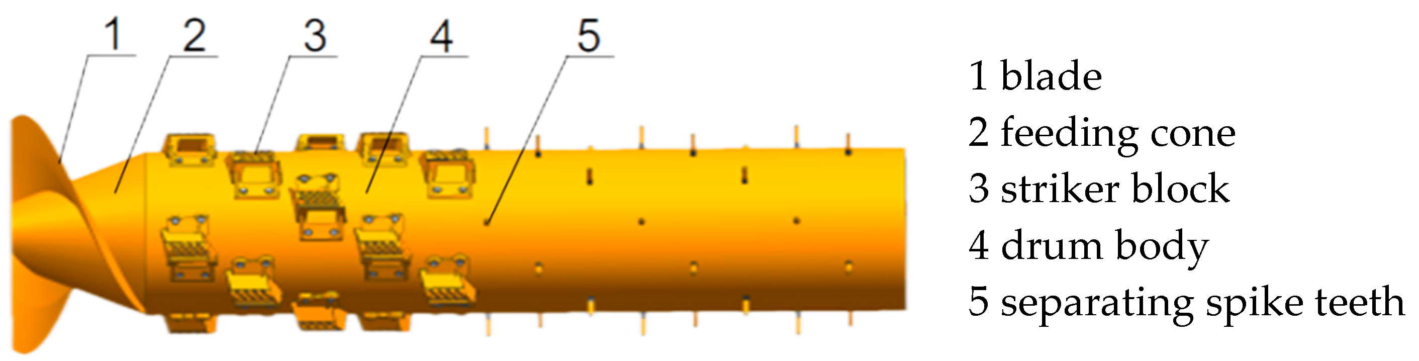
The device mainly includes the drum body, ripple rod block, separation of spike teeth, feeding cone, and other components. When the operation of the corn ear entering the feeding cone blades begins, it will be forced into the drum and concave plate threshing chamber; and then into the ripple rod block on the guide plane under the guidance of the realization of the corn ear attitude of the axial adjustment, to achieve a parallel position to the threshing drum axis of the posture; and then with the rotation of the drum, the corn ear experiences the centrifugal force and gravity under the double action of the ear entering into the threshing gap, by the threshing element crown arc-shaped grain teeth and concave plate sieve bar mutual extrusion rubbing [14], to achieve the separation of the kernel and ear axis, as shown in Figure 1. In order to further improve the threshing efficiency, combined with the lack of peripheral support for the corn, the periphery of the threshing force is significantly reduced in the threshing arc-shaped grain teeth at the end of the threshing with the reinforcement of threshing prongs to achieve the overall detachment of the threshing area and adjacent rows of kernels, to create the next cycle of threshing in a unified condition. The cycle continues, realizing the efficient threshing of corn kernels.
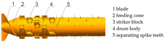
Figure 1.
Schematic structure of a high-striker block-type corn-threshing drum.
The threshing process of corn shares similarities with other crops, where repeated cyclic interactions with threshing elements achieve kernel–ear separation. Assuming each threshing action detaches a proportion p of the remaining kernels (where ), the residual kernel quantity after n cycles can be derived from mechanical reliability theory as follows:
According to China’s Technical Specifications for Corn Kernel Harvesters, the unthreshed kernel rate (typically required to be ≤2.5%) serves as the key performance benchmark. By incorporating the single-cycle detachment efficiency of specific threshing elements, the total number of required elements can be calculated through the following derivation:
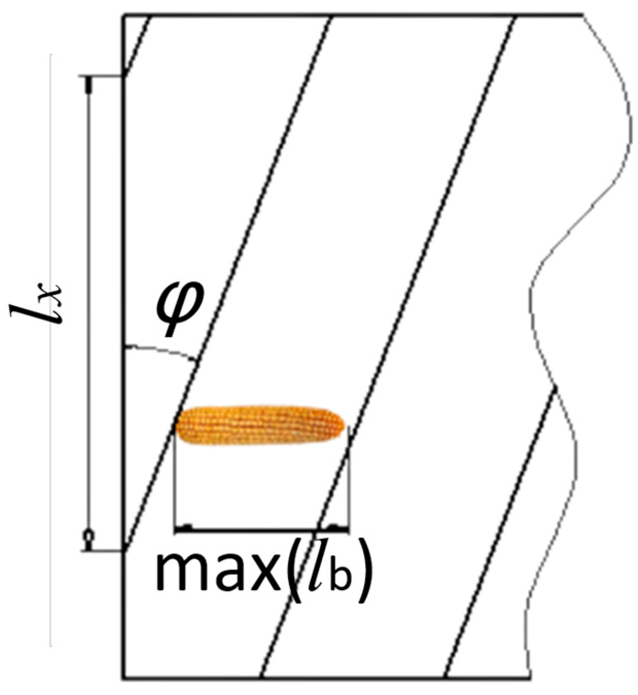
In order to improve the efficiency of corn threshing, combined with the longitudinal-axis flow threshing drum diameter being large, the general threshing elements in the drum use a multi-head helix structure for distribution. Assuming that the threshing drum will expand, we assume the helix and drum end of the angle , two helix drum ends of the distance for , and the maximum length of corn ear for max ; obviously, when the helix and drum end of the angle is greater than the friction angle of the ear and the drum, then the ear will not only be in the threshing element under the push along the axis of the threshing drum movement, but also along the circumferential direction of the threshing drum movement, and with the longitudinal axial flow of threshing element of the cylinder diameter being large, we generally use a multi-head helix structure for distribution. And with the increase in the angle between the helix and the end of the drum, the greater the movement speed of the ear along the circumferential direction of the threshing drum, the more conducive it is to the threshing element to apply the threshing load to it [15,16]. Secondly, by the results of the previous research, when the ear axis is parallel to the axis of the drum, the threshing element will apply the load to the ear. The closer to the tangential direction of the ear, the more conducive to reducing corn-threshing damage (the side of the kernel has a strong resistance to damage strength) and power consumption [17]; thus, in order to enable the ear to be in a position parallel to the axis of the ear, the horizontal position between the two helixes must be left a length of the ear that is in a position parallel to the axis of the threshing drum, as shown in Figure 2.

Figure 2.
Position of the spiral distribution line of the drum threshing element relative to the ear.
From Figure 2,
Thus,
The number of helix heads is
According to the measured data, max(lb) = 250 mm, drum diameter D = 750 mm, tan(φ) = 0.43~0.49, k = 3~4.
2.2. Parameterization of the Guide Plane
- Width of guide plane
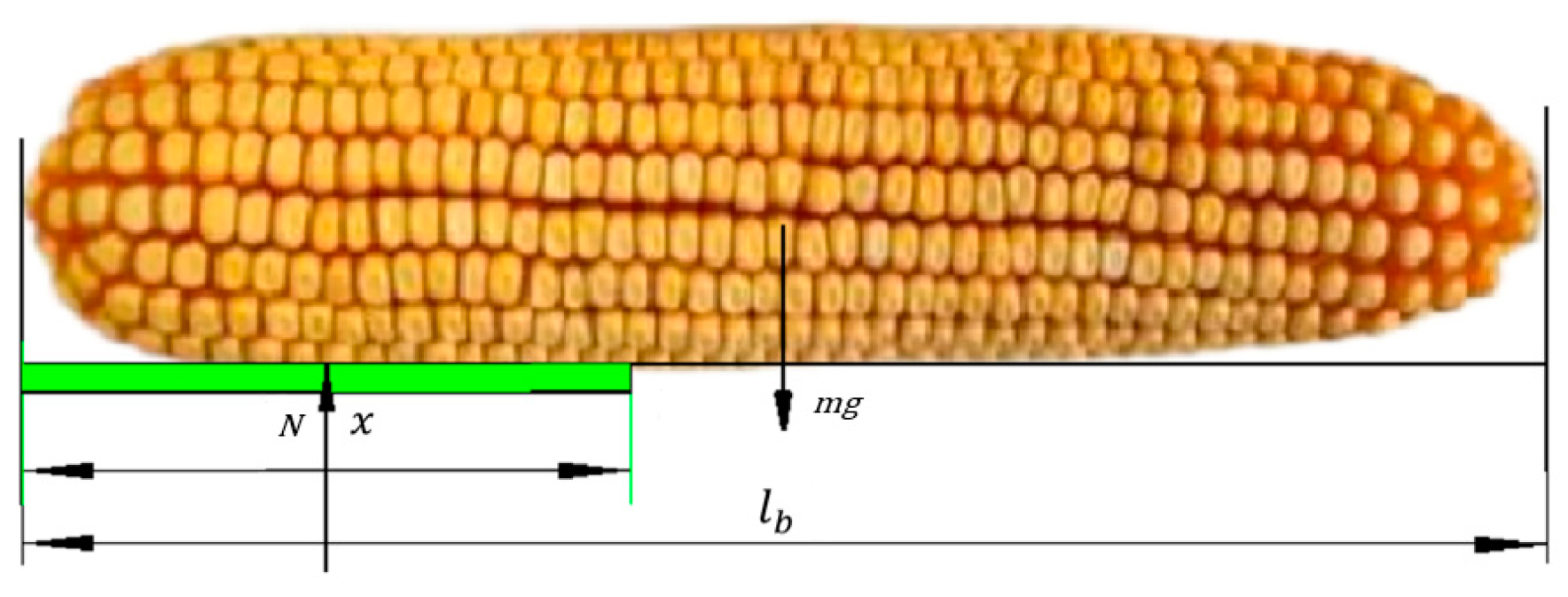
The width of the guiding plane has a very large impact on the corn ear attitude adjustment. If it is too wide, although it can improve the reliability of corn ear attitude correction, it increases the pulsatility and power consumption of the threshing process; if it is too narrow, although it can reduce the pulsatility and power consumption of the threshing process, it will significantly reduce the probability of ear attitude correction, so we assume that an ear is placed on the flat plate at the least desirable position, where the total length of the ear is and the length of the ear placed on the plate is , as shown in Figure 3 .The force analysis of the ear is as follows:
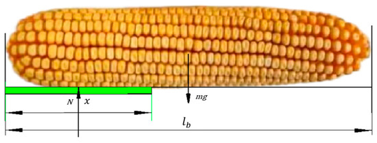
Figure 3.
Conditions for steady-state placement of fruiting spikes on a guide plate.
By , there is
Obviously, to ensure that the ear is placed stably in the guide plane, it is necessary to ensure that the combined moment applied to the ear is 0; thus,
Considering that the sign of the ear flipping around the support point A is N = 0, there is the following:
Considering the variability of the length of the ear, combined with the assurance of the stability of the ear in this guide plane, the width of the guide plane is
Here, ∆ is the allowance for stabilizing width, which is generally taken as 1–3 cm. Substituting the relevant data, the width of the guide plane B is 120~150 mm.
- 2.
- Guide plane angle
The angle of the guide plane is very important for the adjustment of the ear attitude. If the angle is too small, the oblique attitude of the ear may be shifted flatly and it is difficult to ensure the effective adjustment of the ear attitude; if the angle is too large, it will obviously increase the difficulty of the adjustment of the ear attitude, and even lead to the ear jamming in front of the guide plane of the threshing element [18].
In order to ensure that the ear can adjust its attitude along the guide plane, and along the guide plane to slide up to the crown of the threshing element, we selected an ear and threshing element contact limit position, that is, the end of the ear and the threshing element guide plane against it, as shown in Figure 4, assuming that the weight of the ear is mg, the ear is in the role of the thrust force against the threshing element guide plane, the guide plane has a branch counterforce , and the force in the x, y direction of the two components of the force is recorded as ; and because under the action of the thrust , the ear has a tendency to slide along the guide plane, there is also a friction force , whose action position can be approximated as being located in the position of , so that there is the following:
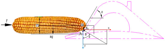
Figure 4.
Force analysis when the ear is against the guide plane.
According to
we obtain
where
—radius of the ear, mm;
—length of the ear, mm;
—coefficient of friction between ear and guide plane;
—weight of the fruit ear, N.
To simplify the problem, let the ratio of the length to the diameter of the ear be k. Then, we have
and
There is, after simplification,
After substituting the relevant data, the angle is 54.09° to 66.65°.
2.3. Parameterization of Threshing Elements
2.3.1. Overall Structure of the Threshing Element
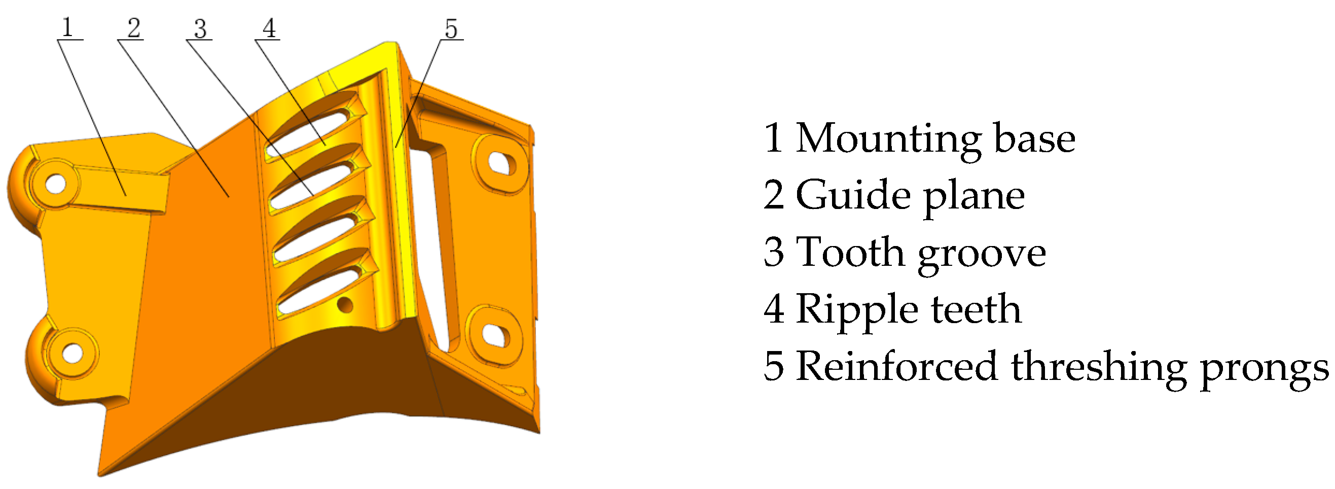
As above, in order to realize the threshing of corn ears with a large feeding capacity, to ensure that the corn ear can be distributed according to the direction parallel to the axis of the drum, and to complete the efficient threshing of the corn ear, the threshing element was developed as shown in Figure 5. When working, the ear is pushed by centrifugal force and other ears to first correct the attitude along the guide plane in the front of the threshing element, realizing the adjustment of the attitude to the direction parallel to the axis of the drum [19]; then it enters the crown of the threshing element, and the separation of the kernels from the ear axis is completed by the stripe tooth group located in the crown of the threshing element, in which the threshed kernels fall through the gaps between the stripe teeth and fall into the lower part of the threshing element or directly slide down the threshing element from the side, leaving separation space for other kernels to be threshed. When the threshing element moves to the end of the grain teeth, the strengthened threshing prongs located at the end of the grain teeth complete the whole row of kernels in the front row of the threshed corn as well as the threshed kernels in the threshed area not yet threshed being threshed, which effectively improves the threshing efficiency of the corn.

Figure 5.
Structure of high-efficiency threshing element.
In the heightened and widened ribbed blocks, the groove width of the ribbed teeth gradually increases and then decreases, as shown in Figure 5. This structural design allows corn kernels on the ear to smoothly enter the ribbed grooves. As the corn ear continues to move forward, the narrowing ribbed grooves cause the top and side surfaces of the kernels to first contact the ribbed grooves on both sides. Simultaneously, the reaction forces exerted by both surfaces of the grooves act on the kernels, working in tandem to detach the kernels from the ear. When the corn ear collides with the component, direct contact with the crown-shaped ribbed teeth at the top enables immediate threshing along these teeth. If the ear contacts the guide plane of the component, its velocity direction forms an angle with the guide plane, allowing it to move upward along the plane to reach the crown-shaped ribbed teeth at the top for threshing. Under the action of these heightened and widened ribbed blocks, targeted threshing forces are applied to the top and side surfaces of the kernels, significantly improving detachment efficiency. After kernel detachment, the structural integrity of the remaining kernels on the ear is compromised, facilitating easier subsequent threshing and effectively reducing grain loss during the threshing process.
2.3.2. Threshing Element Crown Structure
According to the results of previous research, corn threshing is characterized by an uneven distribution of threshing load, i.e., as long as part of the kernel falls off, the threshing load of the kernel adjacent to it will drop significantly, thus effectively reducing the damage to the kernel during the threshing process, so the crown structure of this threshing element was determined to be the combination of a striated teeth–fluted teeth structure. In order to reduce the power consumption of the threshing process, combined with the better load-bearing strength of the main plane of the kernel, the separation of the kernel from the spindle is realized by inserting the top of the striated teeth into the kernel polymerization gap and loading from the main plane of the kernel.
In order to reduce the resistance of the striated teeth inserted into the seed polymerization gap, it is obvious that the striated teeth direction perpendicular to the axial direction of the ear (striated teeth parallel to the main plane of the seed) is best, but when the striated teeth are inserted along that direction, the lateral thrust of the seed is minimized, and the displacement is minimized, which is not conducive to the separation of the seed and ear axes, so the striated teeth are taken as the angle of the striated teeth from the main plane of the seed ɑ smaller than or equal to the friction angle of the striated teeth from the seed, that is, .
According to the measured data, the friction coefficient between the corn kernel and the threshing element is 0.43~0.49, and the angle between the striated teeth and the side plane of the kernel is ≤26.12°.
Further, in order to ensure a complete separation of the seeds from the ear, it is necessary that the striated teeth slide through the ear seed polymerization gap, pushing the removed seeds in the direction of the axis of the ear by a thickness of one seed, so
and
Here,
—seed thickness, mm;
—seed grain width, mm;
—the number of grains that the grain teeth slipped through the gap of seed polymerization of the ear. Here, we take it to be 3~4.
Substituting the measured data, we have .
2.3.3. Thickness of the Teeth of the Bar
Considering that the threshing of the corn ear is accomplished under the synergistic action of the threshing element and the separating concave plate and, in particular, that the striated teeth of the crown of the threshing element are required to cut into the kernel polymerization interface from the side of the ear close to the threshing drum, the striated teeth section is designed as a trapezoidal structure as shown in Figure 6, wherein the structure of the stripe teeth is shown as A-A.
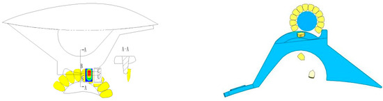
Figure 6.
Position of the threshing element relative to the ear.
Considering that the ear diameter is affected by the growth environment, there is a large degree of randomness, so the tattoo height h is set as the corn kernel height hk based on the addition of a safety factor is
Here, k—tooth height safety coefficient, which can take values of 1.3~1.8.
Substituting into the measured data, we can obtain the height of the grain teeth to be 13.5~18.7 mm.
In order to avoid the stagnation of threshed seeds between neighboring stripe teeth, according to the mechanical reliability design theory and the conditions of seed arching, the spacing between stripe teeth and stripe teeth is designed to be 3 times the thickness of seeds, i.e., 12.54~22.64 mm; the design of permeability between stripe teeth and stripe teeth is adopted, i.e., the threshed seeds can directly pass through the aperture at the bottom of the stripe teeth and leave the loading position of the threshing area, which effectively reduces the damage to the seeds.
2.3.4. Post-Reinforced Threshing Prongs with Striated Teeth of the Ribs
In order to ensure the ear is conveyed backward according to the spiral distribution of the threshing element, improve the threshing strength of the corn ear, and realize the cleaning of all of the kernels in the region swept by the grain teeth of the crown of the threshing element, there is a reinforced threshing prong at the rear of the grain teeth.
According to the distribution curve of the damage-resistant strength of the side of the kernel, the damage-resistant strength of the side of the corn kernel is a non-uniform structure, i.e., the region of maximum damage-resistant strength of the side of the kernel located in the kernel as shown in Figure 6 is , so that it is sufficient to have the height of the striated teeth of the striated rod block to half of the height of the kernel, and thus the threshing gap δ is
Here,
—spindle diameter, mm;
—distance from the position of the average maximum seed damage resistance strength to the grain stalk; considering that the reinforced threshing prong allows a thorough cleaning of the region swept by the grain teeth on the basis of threshing by the grain teeth, in order to ensure that the reinforced threshing prong can both remove the unthreshed kernels in the region (due to the interstitial structure of the grain teeth, there may be some unthreshed kernels left behind) and is not too low against the corn ear axis, we strengthen the threshing prongs more than the crown of the threshing element grain teeth height distance, generally about 2~3 mm.
3. Process Analysis of Corn-Threshing Stage
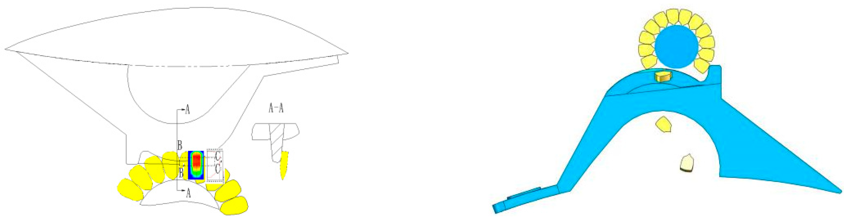
The movement of the corn within the threshing device is generalized to the following stages, namely the complete ear collision stage A, the collision stage B after shedding some kernels, and the kernel shedding and enlargement stage C, as shown in Figure 7.
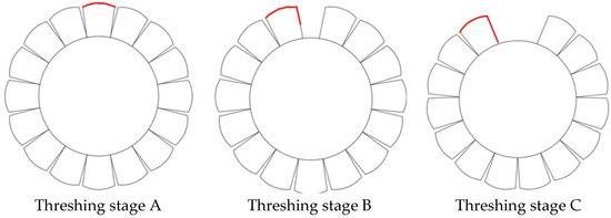
Figure 7.
Different stages of threshing. The red line shows the collidable positions for different scenarios.
The tangential force along the top surface of the corn kernel is the effective threshing force for corn, which is dislodged at stage A of corn threshing by forces such as impact and extrusion from the high-speed rotating threshing element. During this process, the intact corn is coerced by other kernels because of its structural integrity and requires a higher external impact force to provide sufficient threshing force, which is further exacerbated by the fact that the obstruction of the surrounding kernels makes the location of the force of the dislodged kernel more limited. This situation can be generalized as a group aggregation phenomenon hindering the movement of a single object, i.e., the swarming effect of corn kernel threshing.
In the traditional spike tooth element, because of the structural limitations of the spike tooth, in corn ear threshing, a portion of the kernel threshing is not subjected to direct threshing force, but the external element is smashed into the corn to force the corn to be destroyed and thus drive the surrounding kernels to fall off. Threshing stage A is impacted by the corn because of the positional limitations of the corn to bear the majority of the impact load, so the probability of corn kernel breakage in the corn-threshing process in threshing stage A is higher than in the other stages. Higher than in other stages, and traditional threshing elements such as spike teeth or rod teeth, the highest efficiency of threshing contact occurs for the top of the element and the corn ear collision contact, but the probability of this collision occurring is small; thus, for threshing stage A, designs for the widening and heightening of the stripe rod block threshing element can be a good solution to the initial threshing stage of the threshing element, and the corn effective contact area is not enough to solve this phenomenon [20,21].
At the beginning of kernel shedding, kernels have been shed around the kernel to lose part of the kernel coercion, and its role in the effective area of the kernel increases and the effective collision angle has a greater range than before, as shown in Figure 7 of threshing stage B. At this time, the kernel‘s need for an external impact force is lower than at the beginning of the kernel, when there continues to be kernel shedding, its advantage continues to expand, and the need for external threshing impact force continues to decrease; at this time, the corn can be threshed with a smaller impact force, greatly reducing the corn breakage rate in threshing stage C.
For the traditional elements and corn ear collision position limitations, the design of the widening and heightening of the crest block-type threshing element in the threshing process encountering the non-top position can be slid along the guiding plane to the top of the crown grain teeth, and thus the corn ear and the crown grain teeth collision for threshing. This element can optimize the frequency and area of contact between the top side of the corn kernel and the element when the ear collides with the element, so that more kernels fall off at the first time of threshing, reducing the clustering effect of the corn kernels, and reducing the coercive force between kernels in other positions of the corn, and at the same time, increasing the effective contact area and improving the angle of collision when the corn is being threshed, so that the kernels can be successfully shed when subjected to small loads.
According to the different stages of corn threshing, we carry out experiments on the mechanical properties of kernels to study the nature of kernel shedding. Firstly, we carry out experiments on the threshing of intact corn ear, then we carry out experiments on the shedding of neighboring kernels and non-neighboring kernels after the shedding of a single kernel and carry out experiments on the effect of the shedding force of the shed kernels on the surrounding kernels to study the difference between intact ear and non-intact ear threshing and to analyze the effect of clustering effect between kernels on corn threshing.
4. Experimental Section
This paper studies the mechanical properties of corn kernels in the threshing process. First of all, we examine the physical properties of corn kernels, because the moisture content is one of the most important factors affecting the mechanical properties of corn kernels, and the moisture content of corn in the threshing process of the threshing force is different. We determine the moisture content of the batch of corn as a basis for the study of the mechanical properties of corn kernels.
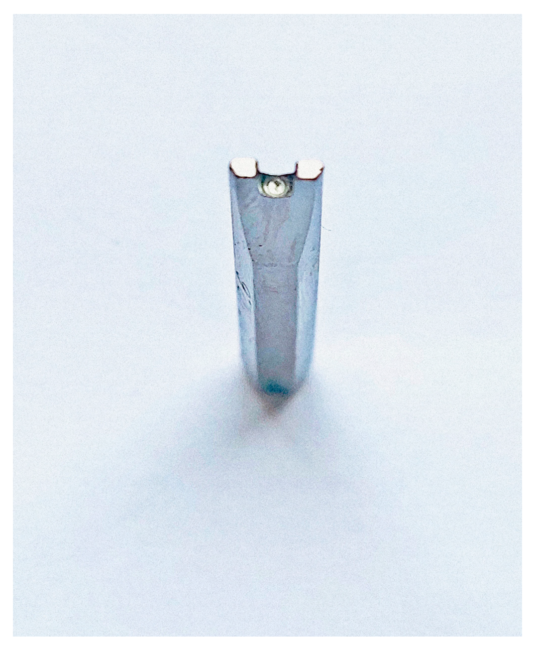
The test is selected during the harvest period of the Yellow Huaihai region’s widely grown varieties of Jinyu 235, obtained during the harvest, selecting the shape and size of the corn ear as basically the same 50, according to the relevant standards GB/T3543-1983 [22] in the test kernel moisture content method. This paper uses a moisture meter for the testing of maize kernels for the determination of their moisture content, according to the moisture meter operation instructions. We selected corn ear hand threshing for moisture content measurement and measured corn basic characteristic parameters such as a moisture content of 11°. The test equipment includes a universal testing machine WDS-5 (SHSIWI Co., Shanghai, China), an SITC brand grain moisture meter LDS-1G (LUHAIFENG Co., Dezhou, China), a Li Chen brand electronic precision analytical balance LC-FA1004 (YUEPING Co., Shanghai, China), a micrometer, and a special concave thimble with an area of 2 mm2, as shown in Figure 8.
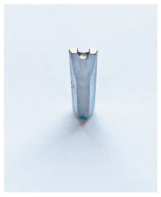
Figure 8.
Concave thimbles.
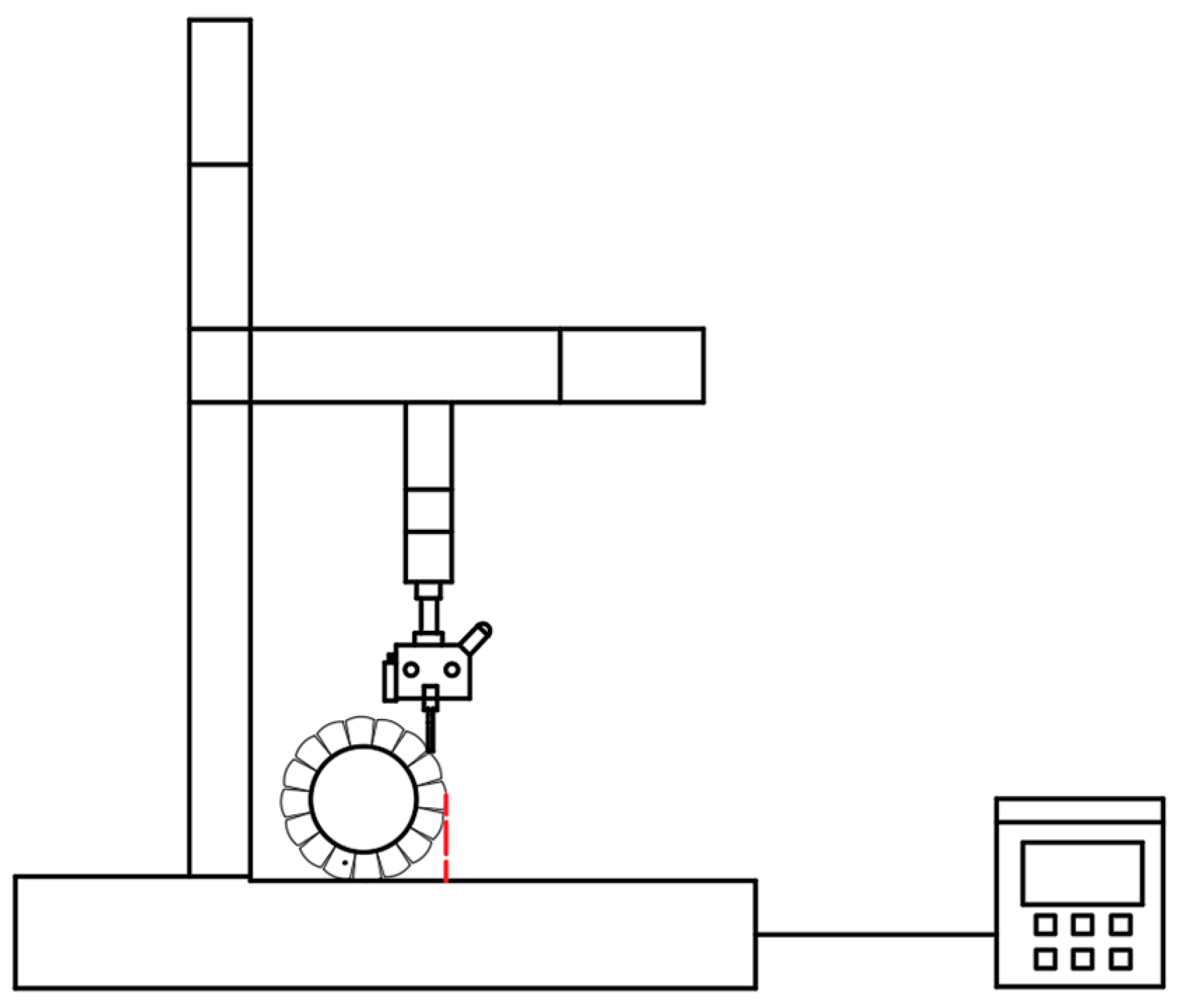
This experiment uses a specially designed concave thimble with an area of 2 mm2 as the corn contact force component of the corn load impact experiment to simulate heightening and widening to determine the magnitude of the corn-threshing force under various conditions. Figure 9 below is a sketch of the universal testing machine, taking into account the actual threshing process of corn, in which the contact surface is mostly the top surface as well as the top side—although the front side has the largest damage resistance, in practice, it rarely bears the load; thus, in this experiment, the top side was loaded with stress loads. First of all, in the complete ear threshing experiment on the experimental complete ear, the lateral load on the corn can give the corn the smallest force for shedding, but it is also in line with the effective contact position of the threshing element and ear contact at this time, in order to ensure that the subsequent kernel loading experiments are on the top of the side of the force direction and position of the same, to apply the load of the kernels below that are adjacent as a baseline reference, and the top of the tangent line with the horizontal perpendicular (as marked by the red line), as shown in Figure 9. Subsequently, the load was applied to the corn after shedding one kernel to investigate the effect of the loss of stress on the threshing force of the remaining kernel after shedding part of the kernel. The experiments were then followed in sequence according to the experimental program.
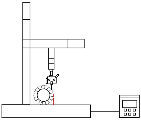
Figure 9.
Test force position and direction standard.
4.1. Experimental Scenarios
The following protocols were designed for validation tests to address the clustering effect among maize.
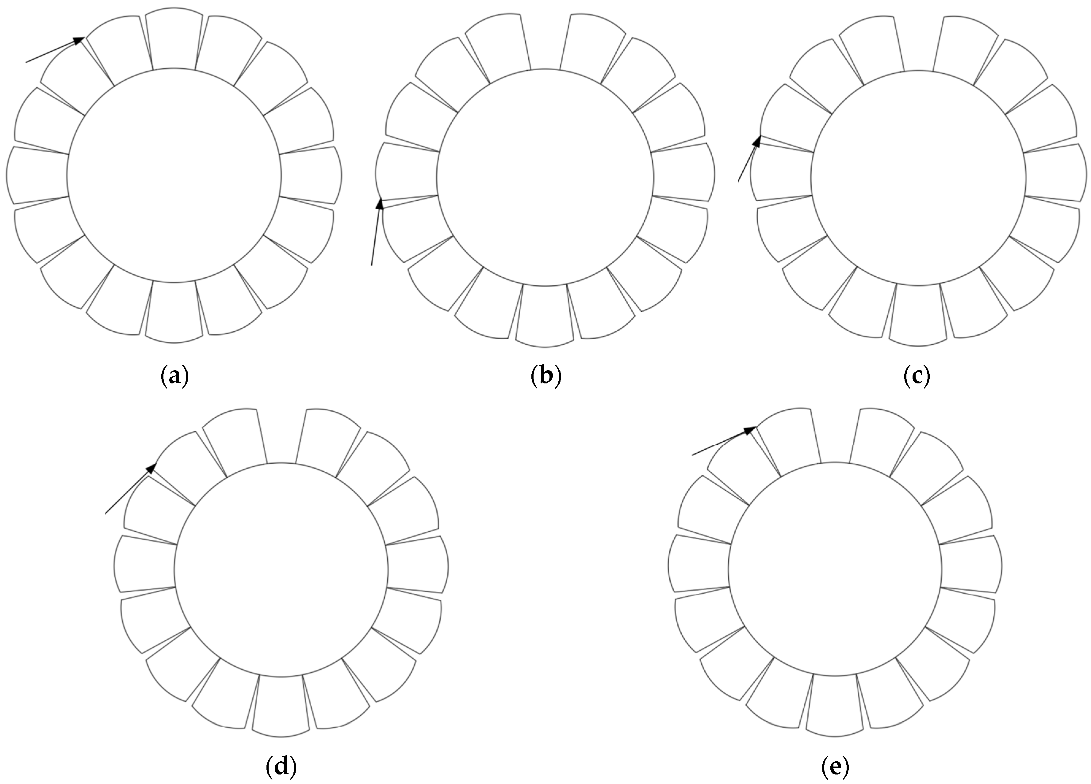
For this test, a 2 mm2 concave thimble was installed to the fixture, the motion speed of the universal testing machine was pre-adjusted to 100 mm/min, and the corn ear was loaded in accordance with the loading position in Figure 10 to ensure the consistency of the loading position. The threshing test was first performed on an intact ear, repeated 10 times, and the results were counted. After that, each test used a new intact corn ear in the first manual threshing, shedding a corn kernel, in turn, according to the loading interval of the test program b-e, followed by the end-of-test statistical results, testing a total of 50 groups.
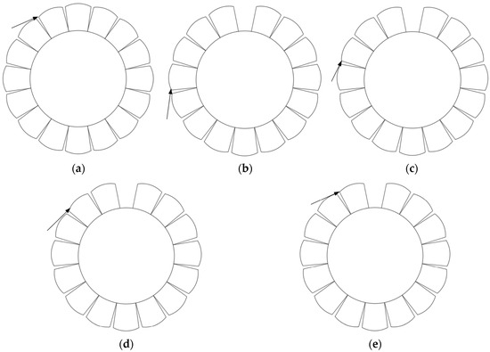
Figure 10.
Illustrations and sequence numbers of each test scheme. (a) Test program a; (b) Test program b; (c) Test program c; (d) Test program d; (e) Test program e.
4.2. Test Results
The results of the test are shown in Table 1.

Table 1.
Test data for each program.
The experimental data were analyzed and organized in the following table.
From the experimental data, it can be seen that in the whole threshing experiment, the force of a kernel dislodging when the corn ear is intact is the largest, with a mean value of 42.86 N. After a kernel is dislodged, the kernel dislodging force decreases at any of the above-mentioned positions of the test. When a seed is dislodged, even if the dislodged seed is farther away from the initially threshed seed, the force of threshing the seed is decreased, as in test b, when the force of threshing the seed is 29.78 N. The force of threshing the seed is decreased when the seed is dislodged, even if the dislodged seed is farther away from the initially threshed seed.
In scenario b, the threshing force decreased significantly. It can be seen that the clustering effect between the kernels on the effect of threshing force is obvious, and the range of influence is larger; when there are kernels falling off, destroying the clustering effect, the kernel shedding force decreases rapidly. This test result verifying the corn threshing has a threshing load non-equilibrium distribution of the characteristics of corn threshing; that is, as long as some of the kernels are falling off, then the kernels with their neighboring positions will experience a significant decrease in the conclusion of the load of the kernel threshing.
In program c and program d, the seed shedding force continues to decline, this is because the closer the seeds are that have been shed, the more obvious the influence of the clustering effect. The clustering effect between the seeds is between the seeds constitute each other. When the clustering effect occurs, the effect occurs more strongly the smaller the number of grains, although the value of the change is low, but the efficiency is more obvious; when the number is too high, there will be a certain loss, such as from experiment a to experiment b, where the ratio is less than 2; from experiment a to experiment b, where the ratio is less than 2; from experiment a to experiment b, the ratio is less than 2; and from experiment a to experiment b, the ratio is less than 2. This is because the transfer of force between corn kernels is not in a straight line, resulting in the transfer force on the corn being a fraction of the force on neighboring kernels, so the more kernels there are, the greater the transfer loss, as shown in Table 2.
Table 2.
Analysis of test data.
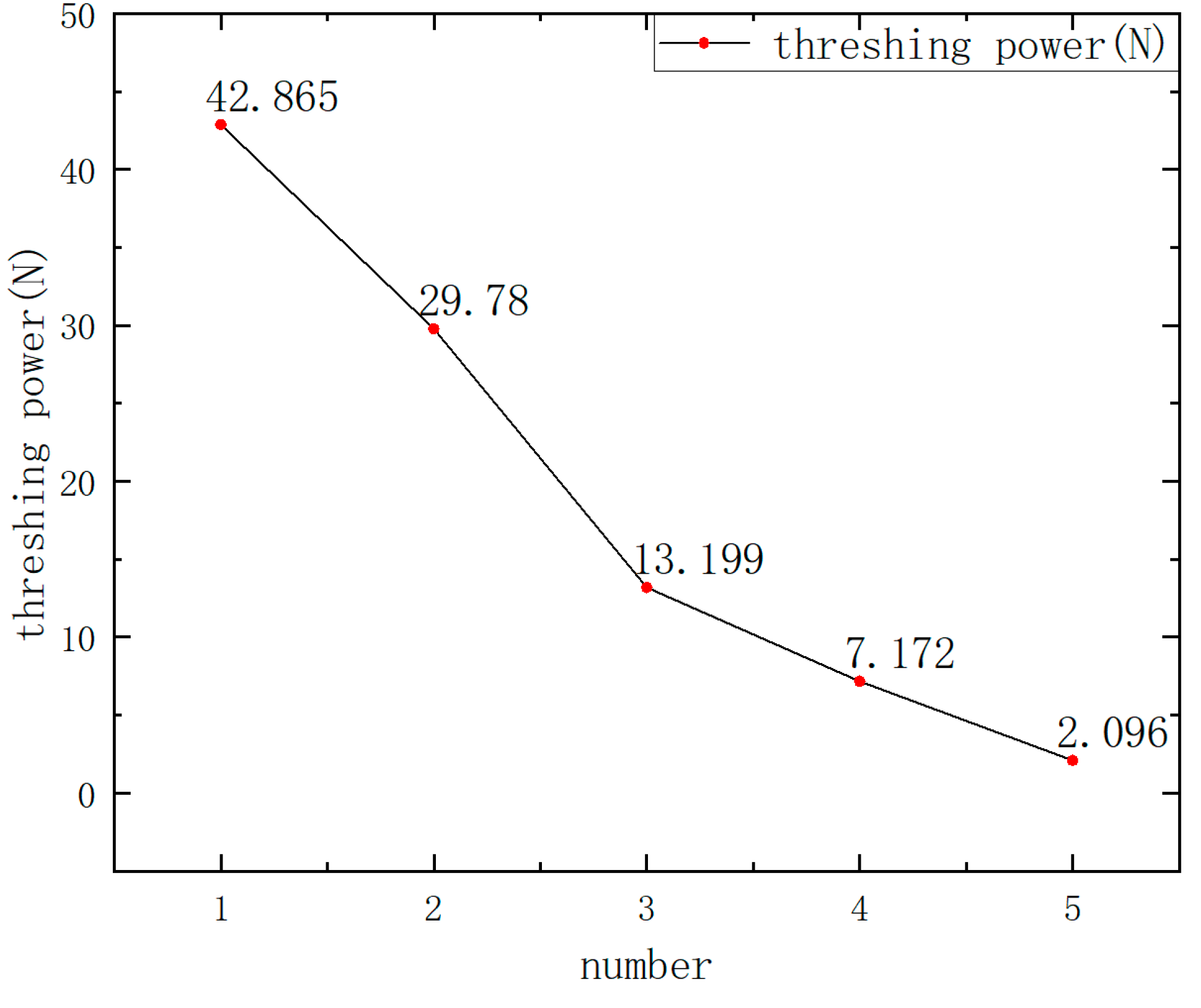
As shown in Figure 11, serial numbers 1–5 correspond to trials a–b one by one, it can be seen that from the beginning when the ear is intact to the position where the kernel applying the load is gradually close to the kernel that has been dislodged, its entire corn kernel dislodging force gradually becomes smaller, and the rate of decline in the first half is faster than that in the second half, and the kernel dislodging force of its corn ear is the largest when it is intact and has the value of 42.86 N. The shedding force was the smallest when the kernel to which the load was applied was closest to the position where the kernel had been shed, with a mean value of 2.09 N. When in the test 3-c position, the shedding force of the kernel drops significantly, and its value is 13.19 N; subsequently, its shedding force continues to decline, but the decline is not high, and at this time the threshing has become easier. According to the time and the position of the kernel that has been dislodged at the time of the experiment, it can be seen that, if in the process of corn threshing, in the same radial direction, the first uniformly dislodged 3–4 kernels around the kernels of the shedding force can reach a desirable range.
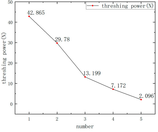
Figure 11.
Changes in corn kernel stress.
5. Discussion
In this study, a theoretical method was used to design a taller and wider ripple block for the swarming effect when the corn ear is pre-complete, so that more kernels can be shed to make the subsequent threshing smoother, and the veracity of this phenomenon was verified through testing, which proved that when some kernels are shed, the shedding force of the surrounding kernels will be significantly reduced, which provides the basis for the design of this threshing element. In this test, the effect of the dislodged kernels on the subsequent threshing of kernels was measured in the same radial direction, ignoring the interactions between kernels oriented in the direction of the corn axis, and therefore, in subsequent research, we will continue to delve into the influence of the cluster effect of corn kernels to expand the scope of the research.
6. Conclusions
1. In this paper, for the corn-threshing process, the complete ear threshing difficulty and the grain damage rate are high. Regarding this phenomenon, the design can help to improve the corn and element collision attitude and collision priority for part of the grain off the wider and taller ripple bar block-type corn-threshing element, so that the complete ear can shed more grains, caused by the ear grain integrity damage, resulting in easier threshing and reducing the loss from threshing.
2. For the designed wider and taller ripple block-type corn longitudinal-flow threshing drum, threshing principle and motion process analysis was carried out, and the parameters of the threshing process were determined, including the overall layout structure parameters, the main parameters of the threshing element, the guiding plane parameters, the structural parameters of the crown of the threshing element, and the thickness of the ripple teeth parameters.
3. The maize-threshing-stage process was analyzed, and the swarming effect of maize kernel threshing was proposed: the phenomenon of group aggregation hindered the motion of individual objects, while the inference was verified in subsequent tests.
Author Contributions
Conceptualization, L.N. and D.G.; methodology, L.N. and D.G.; software, L.N.; validation, L.N., D.G. and X.W.; formal analysis, L.N. and D.G.; investigation, P.G. and X.W.; resources, P.G.; data curation, Y.W. and Y.W.; writing—original draft preparation, L.N.; writing—review and editing, D.G.; visualization, X.W. and Y.W.; supervision, D.G. and P.G.; project administration, Y.W.; funding acquisition, D.G. All authors have read and agreed to the published version of the manuscript.
Funding
This research was supported by the Natural Science Foundation of Shandong Province (ZR2022ME064). This research was supported by the National Key Research and Development Plan (2021YFD20000502).
Institutional Review Board Statement
Not applicable.
Data Availability Statement
Data are contained within the article.
Conflicts of Interest
The authors declare no conflicts of interest.
References
- Srison, W.; Chuan-Udom, S.; Saengprachatanarug, K. Design factors affecting losses and power consumption of an axial flow corn shelling unit. Agric. Nat. Resour. 2016, 38, 421–425. [Google Scholar]
- Petkevichius, S.; Shpokas, L.; Kutzbach, H.-D. Investigation of the maize ear threshing process. Biosyst. Eng. 2008, 99, 532–539. [Google Scholar] [CrossRef]
- Kiniulis, V.; Steponavičius, D.; Andriušis, A.; Kemzūraitė, A.; Jovarauskas, D. Corn ear threshing performance of filler-plate-covered threshing cylinders. Mechanics 2017, 23, 714–722. [Google Scholar] [CrossRef]
- Karalius, D.; Pužauskas, E.; Zokaitis, K.; Steponavičius, D. Pobūgnio skersinių juostų formos įtaka kukurūzų grūdų separacijai ir sužalojimui. Agroinž. Ir Energ.: ASU Žemės Ūkio Inžinerijos Fak. Moksl. Popul. Ir Gamyb. Žurnalas. 2016, 21, 51–56. [Google Scholar]
- Zong, C.; Ke, W.; Yin, G.; Rui, X.; Lu, L.; Bo, M. Current Status of Maize Mechanical Grain Harvesting and Its Relationship with Grain Moisture Content. Sci. Agric. Sin. 2017, 50, 2036–2043. [Google Scholar]
- Tao, T.; Xinhua, W. Finite Element Analysis of Maize Seed under Impact Loading With Nail tooth Corn Thresher. J. Agric. Mech. Res. 2019, 41, 35–39. [Google Scholar] [CrossRef]
- Chen, F.; Tao, C.; Dong, Z.; Yang, L.; Qu, Z.; Yu, L. Design and Test of Low-damage Combined Corn Threshing and Separating Device. Trans. Chin. Soc. Agric. Mach. 2019, 50, 113–123. [Google Scholar]
- Zhi, D.; Zhong, C.; Hua, Z.; Jin, Z.; Ming, Z.; Ling, B. Design and experiment of rasp bar and nail tooth combined axial flow corn threshing cylinder. Trans. Chin. Soc. Agric. Eng. 2018, 34, 28–34. [Google Scholar]
- Zhong, T.; Yao, L.; Li, X. Effects of different threshing components on grain threshing and separating by tangential-axial test device. Trans. Chin. Soc. Agric. Eng. 2011, 27, 93–97. [Google Scholar]
- Li, Y.; Hongchang, L.; Lizhang, X. Comparative experiments on threshing performance between short-rasp-bar tooth cylinder and spike tooth cylinder. Trans. Chin. Soc. Agric. Eng. 2008, 24, 139–142. [Google Scholar]
- Yuan, S.; Hao, L.; Yang, X.; Tao, C.; Zhe, Q.; Dongxing, Z. Optimization and Experiment of Spike-tooth Elements of Axial Flow Corn Threshing Device. Trans. Chin. Soc. Agric. Mach. 2018, 49, 258–265. [Google Scholar]
- Xin, L.; Ying, L.; Yi, M.; Zhe, D.; Fu, M. Effect of Gap Direction Among Corn Ear Kernels on the Circulating Dint Decline. J. Agric. Mech. Res. 2015, 37, 183–187. [Google Scholar] [CrossRef]
- Xin, L.; Ying, L.; Zhe, D.; Yi, M.; Ling, G.; Fuli, M. Experimental Effect of Arrangement Law of Corn Ear Kernels on the Discrete Performance. J. Agric. Mech. Res. 2014, 36, 186–191. [Google Scholar] [CrossRef]
- Wusman, W.; Sattar, S.; Keram, R.; Zulipiya, A. Optimization design of gap-adjustable corn threshing device. J. Chin. Agric. Mech. 2023, 44, 93–99. [Google Scholar] [CrossRef]
- Tao, J.; Hai, L.; Ming, H.; Min, Z.; Mei, J.; Zhuo, G. Design and Experiment of Spiral Interlaced Threshing Cylinder for Combine Harvester. Trans. Chin. Soc. Agric. Mach. 2025, 56, 314–324. [Google Scholar]
- Luo, Y. Reseach on the Effect of the Relationship Between Corn Thresher’s Spiral Angle and Threshing Characteristic. J. Agric. Mech. Res. 2015, 37, 62–64. [Google Scholar] [CrossRef]
- Xin, L.; Kang, W.; Xin, J.; Chun, G.; Lian, G. Analysis on discrete process of kernels caused by beak pecking corn ear by simulating threshing. Trans. Chin. Soc. Agric. Eng. 2015, 31, 34–40. [Google Scholar]
- Xin, Z.; Wei, Z.; Mei, N.; Zhi, L.; Xing, L.; Hai, L.; Jian, C.; Jin, Y.; Tong, Y. Design and Test of Diversion Device for Reducing the Loss of Fresh Corn Harvester Ear Box. J. Agric. Mech. Res. 2025, 47, 41–47. [Google Scholar] [CrossRef]
- Yan, S.; Jing, C. Optimization Design of Threshing Cylinder Axis Based on ANSYS. Mach. Des. Manuf. Eng. 2014, 43, 42–45. [Google Scholar]
- Zhen, W.; Tao, C.; Dong, Z.; Li, Y.; Xian, H.; Ze, Z. Design and Experiment of Rasp Bar Threshing Element of Corn Combine Harvester. Trans. Chin. Soc. Agric. Mach. 2021, 52, 115–123. [Google Scholar]
- Cheng, J.; Yan, K.; Hong, G. Experimental research on the influence of threshing roller structures on the quality of mechanically-harvested soybeans. Trans. Chin. Soc. Agric. Eng. 2021, 37, 49–58. [Google Scholar]
- GB 3543-1983; Rules for Agricultural Seed Testing. China Standard Press: Beijing, China, 1983. Available online: https://www.chinesestandard.net/PDF/English.aspx/GBT3543.6-2025?GB/T%203543.6-2025_English (accessed on 25 March 2025).


Disclaimer/Publisher’s Note: The statements, opinions and data contained in all publications are solely those of the individual author(s) and contributor(s) and not of MDPI and/or the editor(s). MDPI and/or the editor(s) disclaim responsibility for any injury to people or property resulting from any ideas, methods, instructions or products referred to in the content. |
© 2025 by the authors. Licensee MDPI, Basel, Switzerland. This article is an open access article distributed under the terms and conditions of the Creative Commons Attribution (CC BY) license (https://creativecommons.org/licenses/by/4.0/).